Embed Size (px)
Citation preview

1From Introduction to Solid State Lighting A. Zukauskas, M. S. Shur, and R. Gaska, Copyright © Wiley (2002). Used by permission of John Wiley and Sons, Inc.
http://nina.ecse.rpi.edu/shur/
Solid State LightingArturas Zukauskas 1,2, Michael Shur 2, Remis Gaska 3
1 Institute of Materials Science and Applied Research, Vilnius University, Naugarduko g. 24, LT‑2006 Vilnius, Lithuania
2 Rensselaer Polytechnic Institute, http://nina.ecse.rpi.edu/shur/3 Sensor Electronic Technology, Inc., 21 Cavalier Way, Latham, NY
12110, USA
From a torch to Blue and White LEDsTo Solid State Lamps
Blue LED on Si, Courtesy of SET, Inc.

2From Introduction to Solid State Lighting A. Zukauskas, M. S. Shur, and R. Gaska, Copyright © Wiley (2002). Used by permission of John Wiley and Sons, Inc.
http://nina.ecse.rpi.edu/shur/
Outline
HISTORICAL INTRODUCTIONVISION, PHOTOMETRY AND COLORIMETRY
BULBS AND TUBESINTRODUCTION TO LIGHT EMITTING DIODES
LIGHT EXTRACTION FROM LEDsWHITE LEDAPPLICATIONS OF SOLID STATE LIGHTING
3From Introduction to Solid State Lighting A. Zukauskas, M. S. Shur, and R. Gaska, Copyright © Wiley (2002). Used by permission of John Wiley and Sons, Inc.
http://nina.ecse.rpi.edu/shur/
HISTORICAL INTRODUCTION

4From Introduction to Solid State Lighting A. Zukauskas, M. S. Shur, and R. Gaska, Copyright © Wiley (2002). Used by permission of John Wiley and Sons, Inc.
http://nina.ecse.rpi.edu/shur/
Lighting – prerequisite of human civilization
• 500,000 years ago- first torch• 70,000 years ago – first lamp (wick)• 1,000 BC – the first candle• 1772 - gas lighting • 1784 Agrand
the first lamp relied on research (Lavoisier)• 1826 -Limelight - the first solid-state
lighting device
Limelight
Agrand lamp
Edison bulb (1879)
Yablochkov candle (1876)

5From Introduction to Solid State Lighting A. Zukauskas, M. S. Shur, and R. Gaska, Copyright © Wiley (2002). Used by permission of John Wiley and Sons, Inc.
http://nina.ecse.rpi.edu/shur/
Agrand LampThe design based on the research conducted by
A. L. Lavoisier who discovered that combustion is due to oxygen in the air. The lamp was demonstrated to King George III,
and Agrand was granted an English patent (No 1425 of 1784).
A ten fold gain in light
A tubular wick placed within two concentric tubes and a glass chimney around the burner

6From Introduction to Solid State Lighting A. Zukauskas, M. S. Shur, and R. Gaska, Copyright © Wiley (2002). Used by permission of John Wiley and Sons, Inc.
http://nina.ecse.rpi.edu/shur/
History of Lighting (continued)
• 1772 - gas lighting introduced by Scottish inventor William Murdoch
• Limelight - the first solid-state lighting device (introduced by Thomas Drummond in 1826)
Cylinder of lime (calcium oxide) brought to a state of dazzling brilliancy by the flame of the oxy-hydrogen blowpipe
7From Introduction to Solid State Lighting A. Zukauskas, M. S. Shur, and R. Gaska, Copyright © Wiley (2002). Used by permission of John Wiley and Sons, Inc.
http://nina.ecse.rpi.edu/shur/
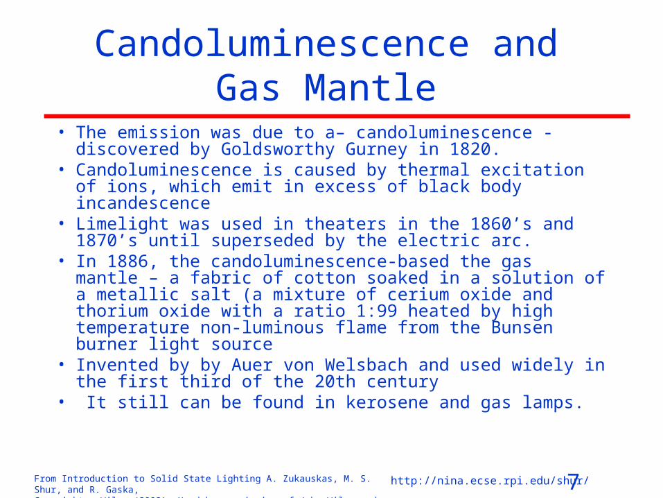
Candoluminescence and Gas Mantle
• The emission was due to a– candoluminescence - discovered by Goldsworthy Gurney in 1820.
• Candoluminescence is caused by thermal excitation of ions, which emit in excess of black body incandescence
• Limelight was used in theaters in the 1860’s and 1870’s until superseded by the electric arc.
• In 1886, the candoluminescence-based the gas mantle – a fabric of cotton soaked in a solution of a metallic salt (a mixture of cerium oxide and thorium oxide with a ratio 1:99 heated by high temperature non-luminous flame from the Bunsen burner light source
• Invented by by Auer von Welsbach and used widely in the first third of the 20th century
• It still can be found in kerosene and gas lamps.
8From Introduction to Solid State Lighting A. Zukauskas, M. S. Shur, and R. Gaska, Copyright © Wiley (2002). Used by permission of John Wiley and Sons, Inc.
http://nina.ecse.rpi.edu/shur/
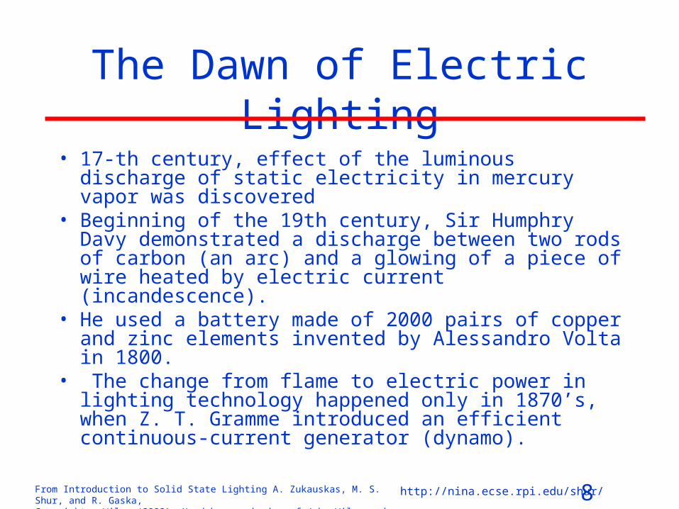
The Dawn of Electric Lighting
• 17-th century, effect of the luminous discharge of static electricity in mercury vapor was discovered
• Beginning of the 19th century, Sir Humphry Davy demonstrated a discharge between two rods of carbon (an arc) and a glowing of a piece of wire heated by electric current (incandescence).
• He used a battery made of 2000 pairs of copper and zinc elements invented by Alessandro Volta in 1800.
• The change from flame to electric power in lighting technology happened only in 1870’s, when Z. T. Gramme introduced an efficient continuous-current generator (dynamo).

9From Introduction to Solid State Lighting A. Zukauskas, M. S. Shur, and R. Gaska, Copyright © Wiley (2002). Used by permission of John Wiley and Sons, Inc.
http://nina.ecse.rpi.edu/shur/
Yablochkov candle
(1876). The first electric lighting
device.
Thomas Alpha Edison bulb
(1879)
10From Introduction to Solid State Lighting A. Zukauskas, M. S. Shur, and R. Gaska, Copyright © Wiley (2002). Used by permission of John Wiley and Sons, Inc.
http://nina.ecse.rpi.edu/shur/
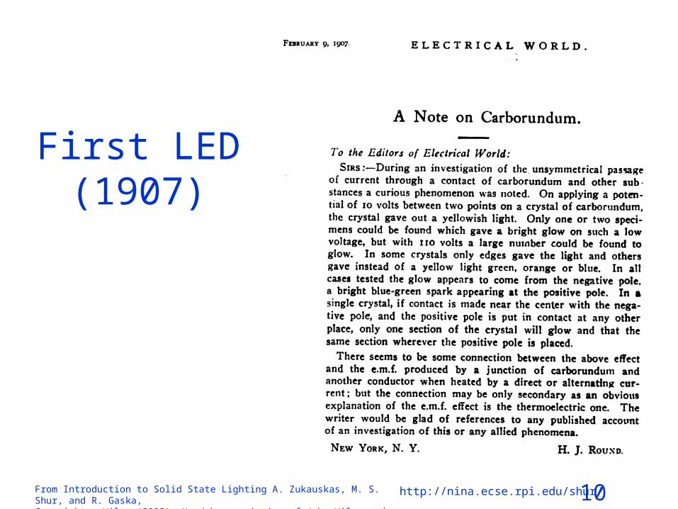
First LED (1907)

11From Introduction to Solid State Lighting A. Zukauskas, M. S. Shur, and R. Gaska, Copyright © Wiley (2002). Used by permission of John Wiley and Sons, Inc.
http://nina.ecse.rpi.edu/shur/
History of Electric Lighting in a nut shell• 1876. Pavel Yablochkov fabricated the first practical electric
lighting device • 1879. Thomas Alva Edison Edison demonstrated his lamp• 1897. Nernst developed a filament made of cerium oxide-
based solid electrolyte. • 1900. Peter Cooper Hewitt patented the mercury vapor lamp.
1903. A. Just and F. Hanaman developed tungsten filament• 1904. C. O. Bastian and A. E. Salisbury combined the
mercury vapor lamp with a low-temperature incandescent lamp
• 1904. Moor introduced discharge lamps using air • 1907 Round reports on the first LED (SiC)• 1910. P. Claude filled discharge lamps with inert gases• 1938. GE and Westinghouse Electric Corporation put on the
market the new colored and white fluorescent lamps.

12From Introduction to Solid State Lighting A. Zukauskas, M. S. Shur, and R. Gaska, Copyright © Wiley (2002). Used by permission of John Wiley and Sons, Inc.
http://nina.ecse.rpi.edu/shur/
Lighting in 2001
• Residential lighting - tungsten incandescent lamps (Or a compact fluorescence lamp (CFL) with higher efficiency)
• Work environments - fluorescence lamp• Street lighting – ugly sodium lamp.
• However, all this is about to change because of explosive development of high brightness visible Light Emitting Diodes
13From Introduction to Solid State Lighting A. Zukauskas, M. S. Shur, and R. Gaska, Copyright © Wiley (2002). Used by permission of John Wiley and Sons, Inc.
http://nina.ecse.rpi.edu/shur/
LIGHTING ECONOMY
14From Introduction to Solid State Lighting A. Zukauskas, M. S. Shur, and R. Gaska, Copyright © Wiley (2002). Used by permission of John Wiley and Sons, Inc.
http://nina.ecse.rpi.edu/shur/
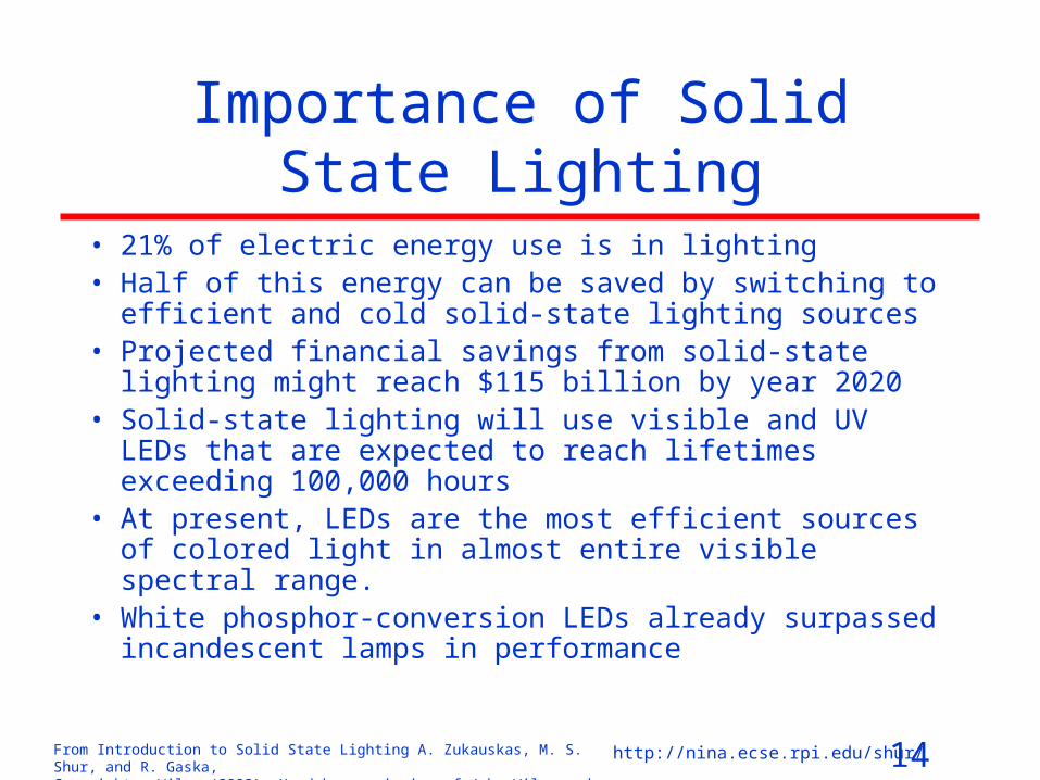
Importance of Solid State Lighting
• 21% of electric energy use is in lighting• Half of this energy can be saved by switching to efficient
and cold solid-state lighting sources• Projected financial savings from solid-state lighting might
reach $115 billion by year 2020• Solid-state lighting will use visible and UV LEDs that are
expected to reach lifetimes exceeding 100,000 hours• At present, LEDs are the most efficient sources of colored
light in almost entire visible spectral range. • White phosphor-conversion LEDs already surpassed
incandescent lamps in performance
15From Introduction to Solid State Lighting A. Zukauskas, M. S. Shur, and R. Gaska, Copyright © Wiley (2002). Used by permission of John Wiley and Sons, Inc.
http://nina.ecse.rpi.edu/shur/
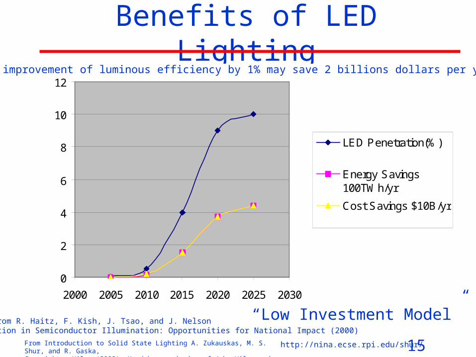
Benefits of LED Lighting
Data from R. Haitz, F. Kish, J. Tsao, and J. NelsonInnovation in Semiconductor Illumination: Opportunities for National Impact (2000)
0
2
4
6
8
10
12
2000 2005 2010 2015 2020 2025 2030
LED Penetration(%)
Energy Savings100TWh/yr
Cost Savings $10B/yr
“Low Investment Model”
An improvement of luminous efficiency by 1% may save 2 billions dollars per year.

16From Introduction to Solid State Lighting A. Zukauskas, M. S. Shur, and R. Gaska, Copyright © Wiley (2002). Used by permission of John Wiley and Sons, Inc.
http://nina.ecse.rpi.edu/shur/
Solid State Lighting
Efficiency (lm/W)FlickersCannot be dimmedLosses in ballastNoisy
Good!
0
20
40
60
80
100
Incandescent Halogen Fluorescent White LED(2000)
White LED(2010)
17From Introduction to Solid State Lighting A. Zukauskas, M. S. Shur, and R. Gaska, Copyright © Wiley (2002). Used by permission of John Wiley and Sons, Inc.
http://nina.ecse.rpi.edu/shur/
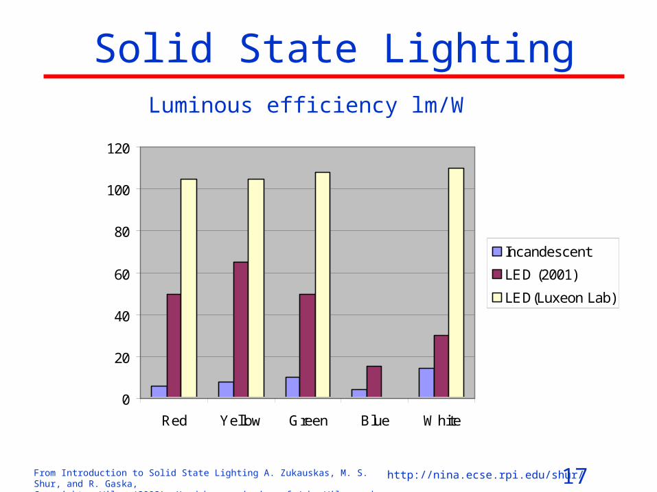
Solid State LightingLuminous efficiency lm/W
0
20
40
60
80
100
120
Red Yellow Green Blue White
Incandescent
LED (2001)
LED(Luxeon Lab)
18From Introduction to Solid State Lighting A. Zukauskas, M. S. Shur, and R. Gaska, Copyright © Wiley (2002). Used by permission of John Wiley and Sons, Inc.
http://nina.ecse.rpi.edu/shur/
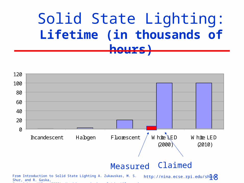
Solid State Lighting:Lifetime (in thousands of hours)
0
20
40
60
80
100
120
Incandescent Halogen Fluorescent White LED(2000)
White LED(2010)
Measured Claimed
19From Introduction to Solid State Lighting A. Zukauskas, M. S. Shur, and R. Gaska, Copyright © Wiley (2002). Used by permission of John Wiley and Sons, Inc.
http://nina.ecse.rpi.edu/shur/
Challenges of Solid State Lighting
• Improve efficiency of light generation• Improve efficiency of light extraction• Improve quality of light • Reduce COST
20From Introduction to Solid State Lighting A. Zukauskas, M. S. Shur, and R. Gaska, Copyright © Wiley (2002). Used by permission of John Wiley and Sons, Inc.
http://nina.ecse.rpi.edu/shur/
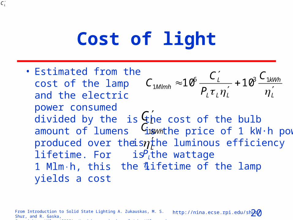
Cost of light
• Estimated from the cost of the lamp and the electric power consumed divided by the amount of lumens produced over the lifetime. For 1 Mlmh, this yields a cost
L
kWh
LLL
LMlmh
C
P
CC
1361 1010
is the cost of the bulb is the price of 1 kW·h power is the luminous efficiency is the wattage the lifetime of the lamp
LC
LCkWhC1
LPL
L

21From Introduction to Solid State Lighting A. Zukauskas, M. S. Shur, and R. Gaska, Copyright © Wiley (2002). Used by permission of John Wiley and Sons, Inc.
http://nina.ecse.rpi.edu/shur/
VISION, RADIOMETRY,
PHOTOMETRY AND COLORIMETRY
22From Introduction to Solid State Lighting A. Zukauskas, M. S. Shur, and R. Gaska, Copyright © Wiley (2002). Used by permission of John Wiley and Sons, Inc.
http://nina.ecse.rpi.edu/shur/
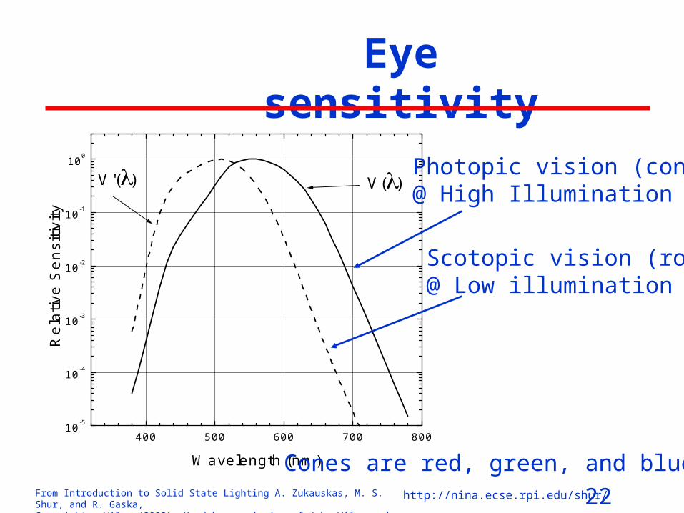
Eye sensitivity
400 500 600 700 80010
-5
10-4
10-3
10-2
10-1
100
V'() V()
Rel
ativ
e S
ensi
tivity
Wavelength (nm)
Photopic vision (cones)@ High Illumination
Scotopic vision (rods)@ Low illumination
Cones are red, green, and blue
23From Introduction to Solid State Lighting A. Zukauskas, M. S. Shur, and R. Gaska, Copyright © Wiley (2002). Used by permission of John Wiley and Sons, Inc.
http://nina.ecse.rpi.edu/shur/
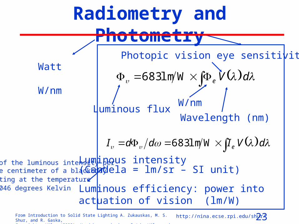
Radiometry and Photometry
dVe Wlm683Watt
W/nm
Luminous intensity(Candela = lm/sr – SI unit)
Luminous efficiency: power into actuation of vision (lm/W)
Photopic vision eye sensitivity
W/nm
Wavelength (nm)Luminous flux
dVIddI e Wlm683
1/60 of the luminous intensity per square centimeter of a blackbody radiating at the temperature of 2,046 degrees Kelvin

24From Introduction to Solid State Lighting A. Zukauskas, M. S. Shur, and R. Gaska, Copyright © Wiley (2002). Used by permission of John Wiley and Sons, Inc.
http://nina.ecse.rpi.edu/shur/
Luminance
• The concept of luminous intensity is not directly applicable to an extended source of light
• Such sources are described by luminance, which is the quotient of the luminous flux propagating from an element of the surface and observed at an angle per unit solid angle
• The luminance is measured in candelas per square meter (cd/m2).
• Scotopic vision dominates at luminance below 10‑2 cd/m2
• Above 10 cd/m2 the vision is completely photopic. • The sun viewed from the sea level exhibits the average
luminance of 1.6×10⁹ cd/m2, and the luminance of the moon is approximately 2500 cd/m2.
25From Introduction to Solid State Lighting A. Zukauskas, M. S. Shur, and R. Gaska, Copyright © Wiley (2002). Used by permission of John Wiley and Sons, Inc.
http://nina.ecse.rpi.edu/shur/
Illuminance
• The measurement unit for illuminance is lumen per square meter, also called lux (lx).
• Sun generates the illuminance on the earth’s surface from 104 lx to 105 lx depending on cloudiness; the illuminance by the moon does not exceed 0.1 lx.
• The higher is the illuminance, the higher is the ability of the eye to distinguish details, small contrasts and color hues. Therefore, different activities require different levels of illuminance.

26From Introduction to Solid State Lighting A. Zukauskas, M. S. Shur, and R. Gaska, Copyright © Wiley (2002). Used by permission of John Wiley and Sons, Inc.
http://nina.ecse.rpi.edu/shur/
How much light do you need?
Type of Activity Illuminance (lx =lm/m2)
Orientation and simple visual tasks (public spaces)
30-100
Common visual tasks (commercial, industrial and residential applications)
300-1000
Special visual tasks, including those with very small or very low contrast critical elements
3,000-10,000

27From Introduction to Solid State Lighting A. Zukauskas, M. S. Shur, and R. Gaska, Copyright © Wiley (2002). Used by permission of John Wiley and Sons, Inc.
http://nina.ecse.rpi.edu/shur/
Colorimetry
350 400 450 500 550 600 650 700 7500.0
0.5
1.0
1.5
2.0
_z
_y_
x
Wavelength (nm)
Chromaticity coordinatesColor temperature Color rendering
dSxX dSyY
dSzZ
1931 CIE color matching functions: “purple” , “green” , and “blue”

28From Introduction to Solid State Lighting A. Zukauskas, M. S. Shur, and R. Gaska, Copyright © Wiley (2002). Used by permission of John Wiley and Sons, Inc.
http://nina.ecse.rpi.edu/shur/
Color Coordinates
0.0 0.2 0.4 0.6 0.8 1.00.0
0.2
0.4
0.6
0.8
1.0
ED65
C
B
A
[R]
[G]
[B]
10,000
6,000
4,0
00
3,0
00
2,0
00
[Z][X]
[Y]
460
640700
620
600
580
560
540
530520
510
500
490
480
400
y C
hro
ma
tic
ity
Co
ord
ina
te
x Chromaticity Coordinate
ZYX
Xx
ZYX
Yy
Is it really that bad?Just remember:White is black!
Planckian locus (black body radiation)
Green
Blue
Red
29From Introduction to Solid State Lighting A. Zukauskas, M. S. Shur, and R. Gaska, Copyright © Wiley (2002). Used by permission of John Wiley and Sons, Inc.
http://nina.ecse.rpi.edu/shur/
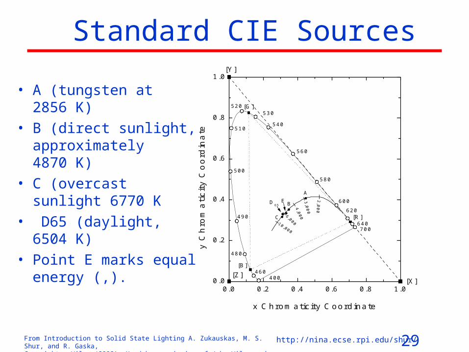
Standard CIE Sources
• A (tungsten at 2856 K)
• B (direct sunlight, approximately 4870 K)
• C (overcast sunlight 6770 K
• D65 (daylight, 6504 K)
• Point E marks equal energy (,).
0.0 0.2 0.4 0.6 0.8 1.00.0
0.2
0.4
0.6
0.8
1.0
ED65
C
B
A
[R]
[G]
[B]
10,000
6,000
4,0
00
3,0
00
2,0
00
[Z][X]
[Y]
460
640700
620
600
580
560
540
530520
510
500
490
480
400
y C
hro
ma
tic
ity
Co
ord
ina
te
x Chromaticity Coordinate

30From Introduction to Solid State Lighting A. Zukauskas, M. S. Shur, and R. Gaska, Copyright © Wiley (2002). Used by permission of John Wiley and Sons, Inc.
http://nina.ecse.rpi.edu/shur/
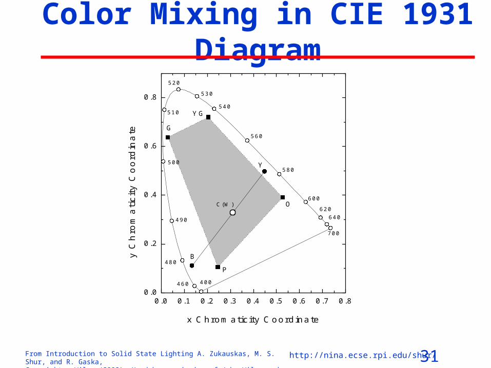
Color Mixing
•Red, green, blue appear as white•Red and blue appear as magenta•Green and blue give cyan•Red and green give yellow
31From Introduction to Solid State Lighting A. Zukauskas, M. S. Shur, and R. Gaska, Copyright © Wiley (2002). Used by permission of John Wiley and Sons, Inc.
http://nina.ecse.rpi.edu/shur/
Color Mixing in CIE 1931 Diagram
0.0 0.1 0.2 0.3 0.4 0.5 0.6 0.7 0.80.0
0.2
0.4
0.6
0.8
YG
G
P
O
Y
B
C(W)
460
640
700
620
600
580
560
540
530
520
510
500
490
480
400
y C
hro
ma
tic
ity
Co
ord
ina
te
x Chromaticity Coordinate
32From Introduction to Solid State Lighting A. Zukauskas, M. S. Shur, and R. Gaska, Copyright © Wiley (2002). Used by permission of John Wiley and Sons, Inc.
http://nina.ecse.rpi.edu/shur/
Color Rendering
0.0
0.2
0.4
0.6
0.8
1.0
Light grayish red
Light bluish green
0.0
0.2
0.4
0.6
0.8
1.0
Dark grayish yellow
Light blue
0.0
0.2
0.4
0.6
0.8
1.0
Strong yellow green
Light violet
400 500 600 7000.0
0.2
0.4
0.6
0.8
1.0
Moderate yellowish green
Re
flect
ivity
400 500 600 700
Light reddish purple
Wavelength (nm)
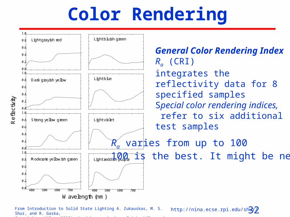
General Color Rendering IndexRa (CRI)integrates the reflectivity data for 8 specified samplesSpecial color rendering indices, refer to six additional test samples
Ra varies from up to 100100 is the best. It might be negative

33From Introduction to Solid State Lighting A. Zukauskas, M. S. Shur, and R. Gaska, Copyright © Wiley (2002). Used by permission of John Wiley and Sons, Inc.
http://nina.ecse.rpi.edu/shur/
Math of Color Rendering (for reference only)
Reference source 8,,1, iSS irr
Test source 8,,1, iSS ikk
USC chromaticity coordinates 31224 yxxu , 31226 yxyv
General color rendering index (CRI)
8
18
1
iia RR
34From Introduction to Solid State Lighting A. Zukauskas, M. S. Shur, and R. Gaska, Copyright © Wiley (2002). Used by permission of John Wiley and Sons, Inc.
http://nina.ecse.rpi.edu/shur/
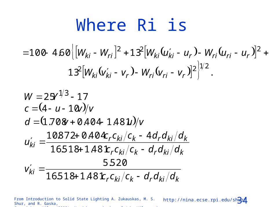
Where Ri is
.13
1360.41002122
222
rririrkiki
rririrkikirikii
vvWvvW
uuWuuWWWR
1725 31 YW
vvuc 104
vuvd 481.1404.0708.1
kkirkkir
kkirkkirki dddccc
dddcccu
481.1518.16
4404.0872.10
kkirkkirki dddccc
v
481.1518.16
520.5

35From Introduction to Solid State Lighting A. Zukauskas, M. S. Shur, and R. Gaska, Copyright © Wiley (2002). Used by permission of John Wiley and Sons, Inc.
http://nina.ecse.rpi.edu/shur/
BULBS AND TUBES

36From Introduction to Solid State Lighting A. Zukauskas, M. S. Shur, and R. Gaska, Copyright © Wiley (2002). Used by permission of John Wiley and Sons, Inc.
http://nina.ecse.rpi.edu/shur/
Normalized emission intensity of the black body (dotted line) and tungsten
radiator (solid line) at 3000 K
300 500 1000 3000
Wavelength (nm)
Re
lativ
e In
t ens
i ty
At present, tungsten incandescent lamps serve most of the needs of residence lighting.

37From Introduction to Solid State Lighting A. Zukauskas, M. S. Shur, and R. Gaska, Copyright © Wiley (2002). Used by permission of John Wiley and Sons, Inc.
http://nina.ecse.rpi.edu/shur/
Incandescent Bulb - A True Challenge • filament is wound into a helix to reduce the heat conducted into surrounding gas• further reduction of gas loss is achieved by secondary coiling of the primary coil• filament is supported by molybdenum wires and electrically connected to the
leads made from nickel or nickel-plated wires. • The design usually comprises a copper-nickel fuse• The bulb is made of soda-lime silicate glass and the cap is made of aluminum or
brass.• Matching of the thermal expansion and stability of the glass-metal seal is
provided by Dumet wires (• bulb is filled with high-atomic-weight inert gas (argon and, rarely, krypton). • nitrogen is used to prevent formation of an arc during the filament failure. • To reduce blackening of the bulb, some getter is added for absorption of any
remainder of oxygen and moisture. • To diffuse and to direct the light, inside frosting and integral reflectors are used• Plus marketing for a total cost of 50 cents

38From Introduction to Solid State Lighting A. Zukauskas, M. S. Shur, and R. Gaska, Copyright © Wiley (2002). Used by permission of John Wiley and Sons, Inc.
http://nina.ecse.rpi.edu/shur/
Tungsten Halogen Lamps
• If the tungsten evaporation rate is reduced, the filament of the incandescent lamp might operate at higher temperature, and the lifetime of the lamp may increase.
• The addition of a halogen to the gas filling is known to establish a chemical transport cycle, in which tungsten forms halides when diffusing from the hot filament towards the cooler wall.
• Tungsten halides diffuse in the opposite direction and dissociate at the filament. The transport cycle results in nearly zero concentration of the tungsten at the bulb wall and in an increased concentration at the filament.
• As a result, filament temperatures as high as 3450 K can be achieved, with a consequent improvement in efficiency.

39From Introduction to Solid State Lighting A. Zukauskas, M. S. Shur, and R. Gaska, Copyright © Wiley (2002). Used by permission of John Wiley and Sons, Inc.
http://nina.ecse.rpi.edu/shur/
FLUORESCENT LAMPS
• When a large enough electric field is applied to a gas, the gas breaks down and partially ionizes. The resulting conductive plasma comprises electrons as well as a mixture of ionized and neutral particles, some of which are excited
• By limiting the electric current limitation (by introducing a
ballast in the circuit), the discharge is prevented from avalanche ionization and stabilized. The fluorescent lamps utilize low-pressure discharge, in which electrons are accelerated to effective temperatures typically of 11,000-13,000 K, while ions remain almost in thermal equilibrium with the environment (310 K).

40From Introduction to Solid State Lighting A. Zukauskas, M. S. Shur, and R. Gaska, Copyright © Wiley (2002). Used by permission of John Wiley and Sons, Inc.
http://nina.ecse.rpi.edu/shur/
FLUORESCENT LAMPS (cont)
• Fast electrons inelastically relax by exciting atoms, molecules and ions, which might emit light.
• At present, two efficient low-pressure discharge emitters are utilized – vapors of mercury and sodium.
• Sodium emits yellow light, which is directly used, mostly for street lighting
• At low pressures, the major part of the emission from mercury atoms is in UV owing to the radiative transition from the excited 3P1 state to the ground state (4.886 eV/253.7 nm).
• In a fluorescent lamp, visible radiation is produced by photoluminescence in phosphors, which are deposited on the wall of a tubular bulb. UV photons reach the wall via radiative transport, i. e. by multiple reabsorption and reemission by other mercury atoms.

41From Introduction to Solid State Lighting A. Zukauskas, M. S. Shur, and R. Gaska, Copyright © Wiley (2002). Used by permission of John Wiley and Sons, Inc.
http://nina.ecse.rpi.edu/shur/
Configuration-coordinate diagrams of activator phosphor ion for radiative (a) and
nonradiative (b) conversion processes
(b)
Nonexcited state
Excited state
Configuration Coordinate
Pot
entia
l En
ergy
(a)
Nonexcited state
Excited state
42From Introduction to Solid State Lighting A. Zukauskas, M. S. Shur, and R. Gaska, Copyright © Wiley (2002). Used by permission of John Wiley and Sons, Inc.
http://nina.ecse.rpi.edu/shur/
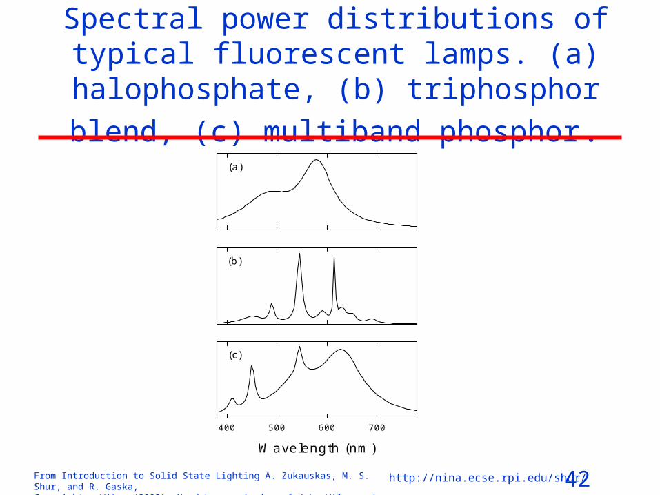
Spectral power distributions of typical fluorescent lamps. (a) halophosphate, (b)
triphosphor blend, (c) multiband phosphor.
400 500 600 700
(a)
Wavelength (nm)
(b)
(c)

43From Introduction to Solid State Lighting A. Zukauskas, M. S. Shur, and R. Gaska, Copyright © Wiley (2002). Used by permission of John Wiley and Sons, Inc.
http://nina.ecse.rpi.edu/shur/
Light output of a typical fluorescent lamp as a function of ambient
temperature
-20 -10 0 10 20 30 40 50 600
20
40
60
80
100
o
Lum
inou
s F
lux
(%)
Temperature ( C)
Optimized for room temperature

44From Introduction to Solid State Lighting A. Zukauskas, M. S. Shur, and R. Gaska, Copyright © Wiley (2002). Used by permission of John Wiley and Sons, Inc.
http://nina.ecse.rpi.edu/shur/
LOW-PRESSURE SODIUM LAMPS
• Since the luminous efficacy of the D-line is about 530 lm/W, the theoretical efficiency of the LPS lamp is extremely high. Despite that 60-80% of the power is wasted for infrared radiation and heat losses, the luminous efficiencies (100-200 lm/W) are the highest among present practical lamps.
• The wattage of the marketed LPS lamps is from 18 to 180 W with the light outputs ranging from 1,800 to 33,000 lm.
• The failure is due to deterioration of cathodes and typical lifetimes are 14,000-18,000 hours.
• The main disadvantage of the LPS lams is a very poor color rendering.
45From Introduction to Solid State Lighting A. Zukauskas, M. S. Shur, and R. Gaska, Copyright © Wiley (2002). Used by permission of John Wiley and Sons, Inc.
http://nina.ecse.rpi.edu/shur/
HIGH-PRESSURE DISCHARGE LAMPS
• Heavy particles (atoms and ions) are heated almost to the same temperatures as the electrons, owing to the high rate of elastic collisions. At pressures of around 1 atmosphere, the temperature of the plasma is typically in the range of 4,000-6,000 K.
• Most of the light is generated in the hot center of the arc. However, because of the temperature gradient, heat flows out of the center decreasing the radiative efficiency to approximately 60%.
• High pressure leads to collision broadening of the line spectra. The resulting wide emission bands considerably improve the color rendering of the light.

46From Introduction to Solid State Lighting A. Zukauskas, M. S. Shur, and R. Gaska, Copyright © Wiley (2002). Used by permission of John Wiley and Sons, Inc.
http://nina.ecse.rpi.edu/shur/
Typical power-distribution spectra of high-pressure discharge lamps.
(a) Clear mercury lamp, (b) improved-color (phosphor-coated) mercury lamp, (c) sodium lamp, (d) metal halide lamp with rear earth (Dy/Ho/Tm)-Na-Tl dose
(a)
(c)
(b)
400 500 600 700
Wavelength (nm)
400 500 600 700
(d)
47From Introduction to Solid State Lighting A. Zukauskas, M. S. Shur, and R. Gaska, Copyright © Wiley (2002). Used by permission of John Wiley and Sons, Inc.
http://nina.ecse.rpi.edu/shur/
Metal Halide Lamps• Luminous efficiency and color rendering of the high-pressure
mercury discharge lamp may by considerably improved by introducing metal halides
• As soon as the tube wall reaches sufficient temperature, a metal halide evaporates and starts a transport cycle
• At the hot core of the discharge, the halide dissociates and produces metal atoms that contribute to the emission. When the metal atoms diffuse towards the cooler region at the wall, they recombine with the halogen to form the halide, which does not react with the wall material.
• The operation pressure of the additive metals is in the range of 10-100 torr (1300-13,000 Pa). Although this pressure is small in comparison with the pressure of mercury (typically 1-20 Atm), the additive metals produce a considerable part of light because their excitation energy (around 4 eV) is lower than that of mercury (7.8 eV).

48From Introduction to Solid State Lighting A. Zukauskas, M. S. Shur, and R. Gaska, Copyright © Wiley (2002). Used by permission of John Wiley and Sons, Inc.
http://nina.ecse.rpi.edu/shur/
Applications
• Diverse wattage, dimensions, and other specification • High brightness and good color rendering characteristics
make them applicable for general lighting services in offices, supermarkets, large stores, and in a lot of industrial and social environments
• High-luminosity units are indispensable for floodlights• Low-power short-arc MH lamps gave birth to new kind of
economic, precise, small-dimension, and long lifetime vehicle headlights.

49From Introduction to Solid State Lighting A. Zukauskas, M. S. Shur, and R. Gaska, Copyright © Wiley (2002). Used by permission of John Wiley and Sons, Inc.
http://nina.ecse.rpi.edu/shur/
Parameters of practical lamps and tubes Type Wattage
(W) Luminous flux init (avrg) (lm)
Eff-cy (lm/W)
aR CCT (CT) (K)
Life-time
(hours)
1 Mlmh price ($)
Incandescent (120 V)
60 865 14.4 100 (2790) 1,000 7.4
Tungsten halogen (120 V)
50 590 11.8 100 (2750) 2,000 12
Fluorescent triphosphor
32 2,850 (2,710)
84 78 4100 24,000 1.6
Compact fluorescent
15 900 (765)
51 82 2700 10,000 3.9
Low-pressure sodium
90 12,750 (11,095)
123 - 44 1800 16,000 1.6
50From Introduction to Solid State Lighting A. Zukauskas, M. S. Shur, and R. Gaska, Copyright © Wiley (2002). Used by permission of John Wiley and Sons, Inc.
http://nina.ecse.rpi.edu/shur/
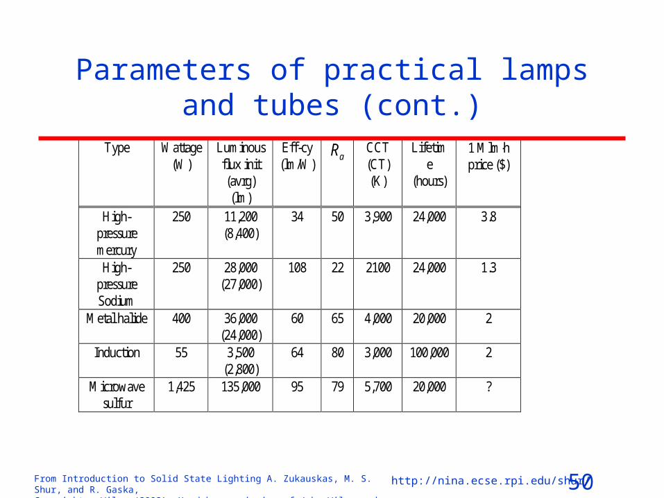
Parameters of practical lamps and tubes (cont.)
Type Wattage (W)
Luminous flux init (avrg) (lm)
Eff-cy (lm/W)
aR CCT (CT) (K)
Lifetime
(hours)
1 Mlmh price ($)
High-pressure mercury
250 11,200 (8,400)
34 50 3,900 24,000 3.8
High-pressure Sodium
250 28,000 (27,000)
108 22 2100 24,000 1.3
Metal halide 400 36,000 (24,000)
60 65 4,000 20,000 2
Induction 55 3,500 (2,800)
64 80 3,000 100,000 2
Microwave sulfur
1,425 135,000 95 79 5,700 20,000 ?

51From Introduction to Solid State Lighting A. Zukauskas, M. S. Shur, and R. Gaska, Copyright © Wiley (2002). Used by permission of John Wiley and Sons, Inc.
http://nina.ecse.rpi.edu/shur/
BASICS OF ALL-SOLID-STATE
LAMPS

52From Introduction to Solid State Lighting A. Zukauskas, M. S. Shur, and R. Gaska, Copyright © Wiley (2002). Used by permission of John Wiley and Sons, Inc.
http://nina.ecse.rpi.edu/shur/
Efficiency and Efficacy
Radiant efficiency: measure of light source ability to convert the consumed power P into radiant flux power
Pee . (W/W)
Luminous efficiency: is measure of light source ability to convert the consumed power P into actuation of the vision
KP e (lm/W)
where K is luminous efficacy: measure of radiation ability of the to produce visual sensation is which is measured in lm/W
eK (lm/W)
53From Introduction to Solid State Lighting A. Zukauskas, M. S. Shur, and R. Gaska, Copyright © Wiley (2002). Used by permission of John Wiley and Sons, Inc.
http://nina.ecse.rpi.edu/shur/
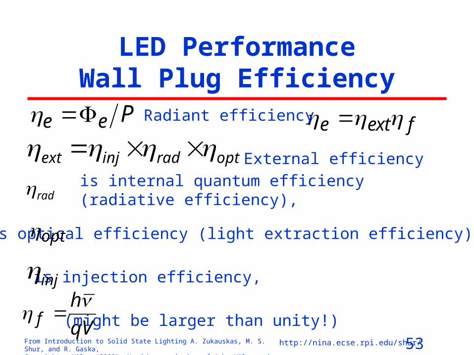
LED Performance Wall Plug Efficiency
fexte
optradinjext is internal quantum efficiency (radiative efficiency),
is injection efficiency,
rad
is optical efficiency (light extraction efficiency), opt
qV
hf
(might be larger than unity!)
Pee
inj
Radiant efficiency
External efficiency

54From Introduction to Solid State Lighting A. Zukauskas, M. S. Shur, and R. Gaska, Copyright © Wiley (2002). Used by permission of John Wiley and Sons, Inc.
http://nina.ecse.rpi.edu/shur/
Recombination of Electrons and Holes
Intrinsic radiative transitions in semiconductors. (a) Band-to-band transitions; (b) free-exciton annihilation; (c) recombination of exciton localized at band-potential fluctuations
Valence
band
Conduction
band
Eg
Eg
(a)
Eg
Valence band
Conduction
band
(b)
Eg
EC
(c)
Eg
EV

55From Introduction to Solid State Lighting A. Zukauskas, M. S. Shur, and R. Gaska, Copyright © Wiley (2002). Used by permission of John Wiley and Sons, Inc.
http://nina.ecse.rpi.edu/shur/
Radiative recombination involving impurity levels. (a) Donor-state–valence-band transition; (b) conduction-
band–acceptor-state transition; (c) donor-acceptor recombination; (d) bound-exciton recombination
(b)
Eg
ED
(c)
Eg
EA
ED
(d)
Eg
ED
(a)
Eg
EA
EC
EV
56From Introduction to Solid State Lighting A. Zukauskas, M. S. Shur, and R. Gaska, Copyright © Wiley (2002). Used by permission of John Wiley and Sons, Inc.
http://nina.ecse.rpi.edu/shur/
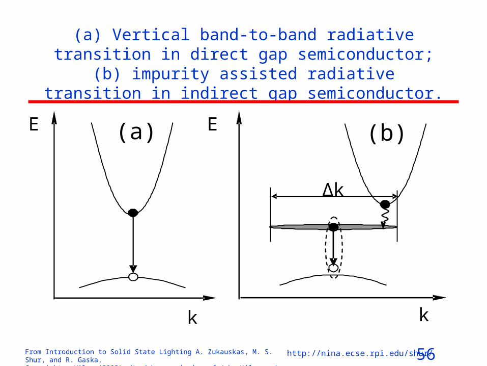
(a) Vertical band-to-band radiative transition in direct gap semiconductor; (b) impurity assisted radiative transition in
indirect gap semiconductor.
E
k
(a)
k
(b) E
Δk
57From Introduction to Solid State Lighting A. Zukauskas, M. S. Shur, and R. Gaska, Copyright © Wiley (2002). Used by permission of John Wiley and Sons, Inc.
http://nina.ecse.rpi.edu/shur/
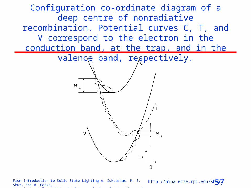
Configuration co-ordinate diagram of a deep centre of nonradiative recombination. Potential curves C, T, and V
correspond to the electron in the conduction band, at the trap, and in the valence band, respectively.
Wh
Q
E
We
V
T
C

58From Introduction to Solid State Lighting A. Zukauskas, M. S. Shur, and R. Gaska, Copyright © Wiley (2002). Used by permission of John Wiley and Sons, Inc.
http://nina.ecse.rpi.edu/shur/
Injection in a p‑n junction LED
(a) Zero bias(b) Forward bias
qV
p
p
n
n
(b)
(a)

59From Introduction to Solid State Lighting A. Zukauskas, M. S. Shur, and R. Gaska, Copyright © Wiley (2002). Used by permission of John Wiley and Sons, Inc.
http://nina.ecse.rpi.edu/shur/
Heterostructures and Quantum Wells
p
n
Eg2
Eg1
EC
EV
60From Introduction to Solid State Lighting A. Zukauskas, M. S. Shur, and R. Gaska, Copyright © Wiley (2002). Used by permission of John Wiley and Sons, Inc.
http://nina.ecse.rpi.edu/shur/
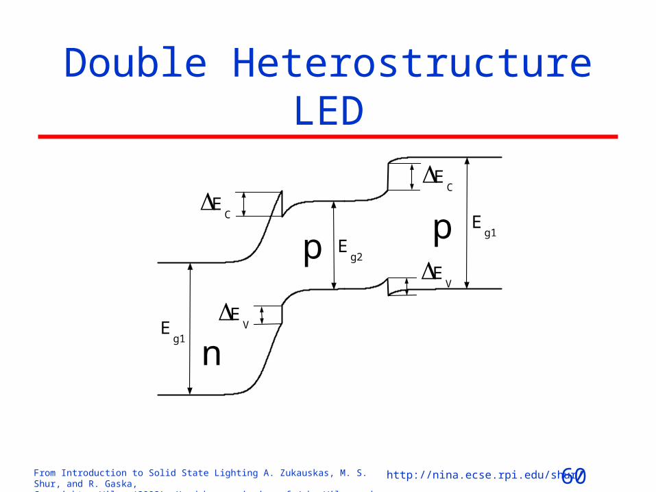
Double Heterostructure LED
p
EV
EC
Eg1
p
n
Eg2
Eg1
EC
EV
61From Introduction to Solid State Lighting A. Zukauskas, M. S. Shur, and R. Gaska, Copyright © Wiley (2002). Used by permission of John Wiley and Sons, Inc.
http://nina.ecse.rpi.edu/shur/
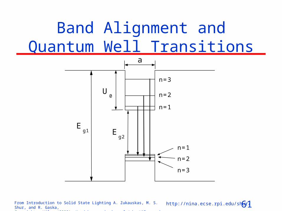
Band Alignment and Quantum Well Transitions
a
U0
n=3
n=2
n=1
n=2
n=3
n=1
Eg2
Eg1

62From Introduction to Solid State Lighting A. Zukauskas, M. S. Shur, and R. Gaska, Copyright © Wiley (2002). Used by permission of John Wiley and Sons, Inc.
http://nina.ecse.rpi.edu/shur/
Effect of the Built-in Field
h
e

63From Introduction to Solid State Lighting A. Zukauskas, M. S. Shur, and R. Gaska, Copyright © Wiley (2002). Used by permission of John Wiley and Sons, Inc.
http://nina.ecse.rpi.edu/shur/
Electron Blocking Layer
U1
U2
ppn
Eg1
Eg3
Eg2
Eg1

64From Introduction to Solid State Lighting A. Zukauskas, M. S. Shur, and R. Gaska, Copyright © Wiley (2002). Used by permission of John Wiley and Sons, Inc.
http://nina.ecse.rpi.edu/shur/
SEMICONDUCTOR MATERIALS SYSTEMS FOR HIGH BRIGHTNESS LEDs
InSbInAsGeGaSbSiInPGaAsCdTeAlSbCdSeInNAlAsZnTeGaPSiC(3C)CdOAlPCdSZnSeSiC(6H)SiC(4H)ZnOGaNZnSCAlN
0 1 2 3 4 5 6 7
Wavelength (nm)2000 800 600 500 400 300 200
Band Gap Energy (eV)
1E-5
1E-4
1E-3
0.01
0.1
1
Re
lativ
e E
ye S
ensi
tivity

65From Introduction to Solid State Lighting A. Zukauskas, M. S. Shur, and R. Gaska, Copyright © Wiley (2002). Used by permission of John Wiley and Sons, Inc.
http://nina.ecse.rpi.edu/shur/
AlGaAs Materials System
5.2 5.6 6 6.40
0.5
1
1.5
2
2.5AlAs
GaAs InP
InAs
Si
Ge
GaP
InSb
GaSb
AlP
Lattice Constant (Å)
66From Introduction to Solid State Lighting A. Zukauskas, M. S. Shur, and R. Gaska, Copyright © Wiley (2002). Used by permission of John Wiley and Sons, Inc.
http://nina.ecse.rpi.edu/shur/
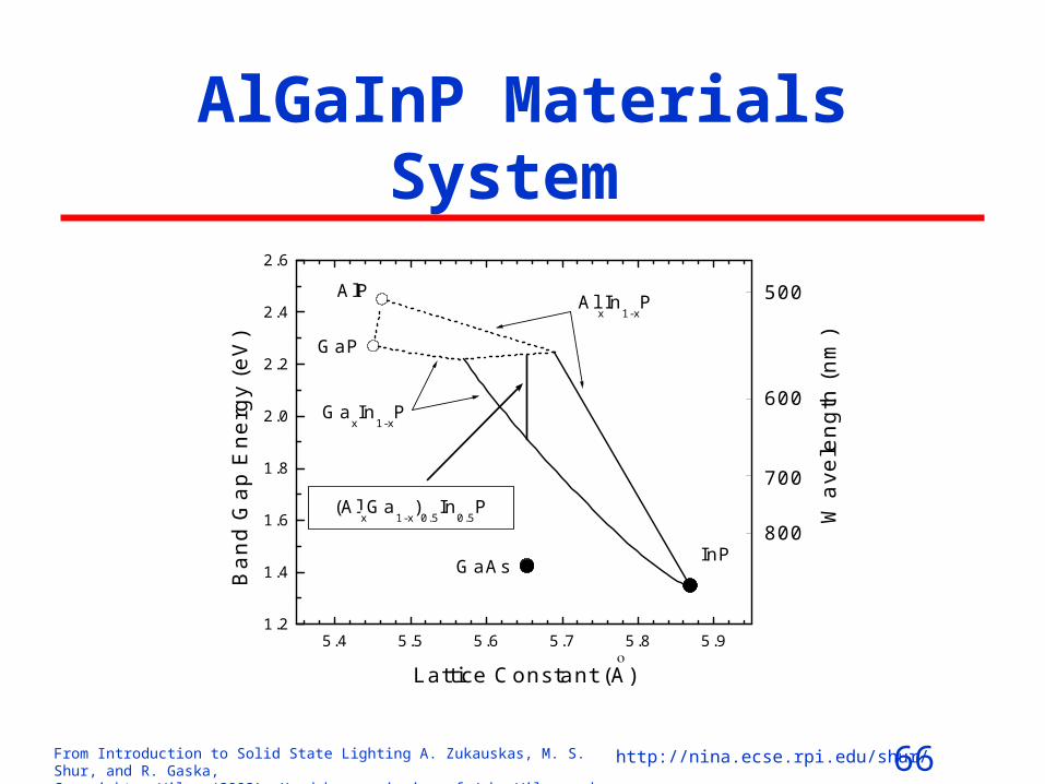
AlGaInP Materials System
5.4 5.5 5.6 5.7 5.8 5.91.2
1.4
1.6
1.8
2.0
2.2
2.4
2.6
(AlxGa
1-x)0.5
In0.5
P
GaxIn
1-xP
AlxIn
1-xP
700
800
500
600
Wa
vele
ngth
(nm
)
AlP
GaP
InPGaAsBa
nd G
ap
Ene
rgy
(eV
)
Lattice Constant (A)
67From Introduction to Solid State Lighting A. Zukauskas, M. S. Shur, and R. Gaska, Copyright © Wiley (2002). Used by permission of John Wiley and Sons, Inc.
http://nina.ecse.rpi.edu/shur/
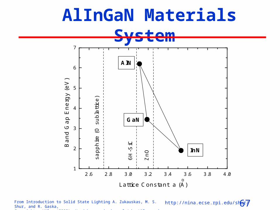
AlInGaN Materials System
2.6 2.8 3.0 3.2 3.4 3.6 3.8 4.01
2
3
4
5
6
7
o
InN
GaN
AlN
6H-S
iC
ZnOsa
pph
ire (
O s
ubl
att
ice)
Ban
d G
ap E
nerg
y (e
V)
Lattice Constant a (A)

68From Introduction to Solid State Lighting A. Zukauskas, M. S. Shur, and R. Gaska, Copyright © Wiley (2002). Used by permission of John Wiley and Sons, Inc.
http://nina.ecse.rpi.edu/shur/
Basic parameters of InN, GaN, and AlN at 300 K Parameter Units GaN AlN InN
Lattice constant, c Ǻ 5.186 4.982 5.693 Lattice constant, a Ǻ 3.189 3.112 3.533
Band gap energy, gE eV 3.339a 6.2 1.97
Effective electron mass, em 0m 0.19b (||) 0.17b ( )
0.33c (||) 0.25c ( )
0.11b (||) 0.10b ( )
Effective heavy hole mass, hhm 0m 1.76c (||) 1.61c ( )
3.53 c (||) 10.42 c ( )
1.56b (||) 1.68b ( )
Effective light hole mass, lhm 0m 1.76c (||) 0.14c ( )
3.53 c (||) 0.24c ( )
1.56b (||) 0.11b ( )
Piezoelectric constant, e31 C/m2 -0.33 -0.48 -0.57 Piezoelectric constant, e33 C/m2 0.65 1.55 0.97
Spontaneous polarization, ||P d C/m2 -0.029 -0.081 -0.032
Radiative recombination coefficiente
cm3/s 4.710-11 1.810-11 5.210-11
Refraction index at 555 nm 2.4 2.1 2.8 Absorption coefficient at the
photon energy gEh 105 cm-1 1 3 0.4
M. E. Levinshtein, S. L. Rumyantsev, and M. S. Shur, Editors, “Properties of Advanced Semiconductor Materials: GaN, AlN, InN, BN, and SiGe“, John Wiley and Sons, ISBN 0-471-35827-4, New York (2001)

69From Introduction to Solid State Lighting A. Zukauskas, M. S. Shur, and R. Gaska, Copyright © Wiley (2002). Used by permission of John Wiley and Sons, Inc.
http://nina.ecse.rpi.edu/shur/
Materials Growth Techniques. LPE
H2
Furnace
Base plate
GaAs Substrate
1st solution: Ga, Al, GaAs, Te
2nd solution: Ga, Al, GaAs, Zn
Slider
Quartz Tube

70From Introduction to Solid State Lighting A. Zukauskas, M. S. Shur, and R. Gaska, Copyright © Wiley (2002). Used by permission of John Wiley and Sons, Inc.
http://nina.ecse.rpi.edu/shur/
MOCVD
MOCVD reactor
Process exhaust
N2
H2
TMGa TMAl TMIn Cp2Mg
PH3 DETe/H2
3-way valve
Mass flow controller
Pressure controller
Bubbler bypass valve
Run/Vent valve

71From Introduction to Solid State Lighting A. Zukauskas, M. S. Shur, and R. Gaska, Copyright © Wiley (2002). Used by permission of John Wiley and Sons, Inc.
http://nina.ecse.rpi.edu/shur/
MOCVD (continued)
After S.Nakamura, Jpn. J. Appl. Phys. 30, L1705, 1991.
IR RadiationThermometer
ConicalQuartz Tube
N2 + H2
Quartz Nozzle
N2 + NH3 + TMG
Vacuum Exhaust
Heater
Substrate
Stainless Steel ChamberChamber
RotatingSusceptor
72From Introduction to Solid State Lighting A. Zukauskas, M. S. Shur, and R. Gaska, Copyright © Wiley (2002). Used by permission of John Wiley and Sons, Inc.
http://nina.ecse.rpi.edu/shur/
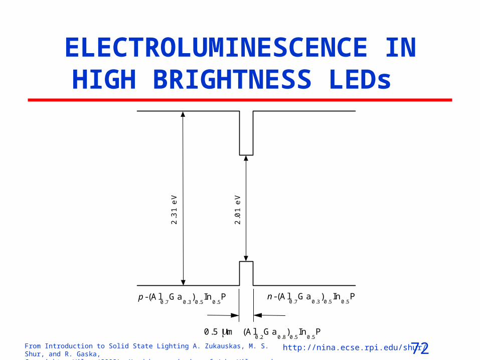
ELECTROLUMINESCENCE IN HIGH BRIGHTNESS LEDs
(Al0.2
Ga0.8
)0.5
In0.5
P
n-(Al0.7
Ga0.3
)0.5
In0.5
P
2.01
eV
2.31
eV
0.5 m
p-(Al0.7
Ga0.3
)0.5
In0.5
P
73From Introduction to Solid State Lighting A. Zukauskas, M. S. Shur, and R. Gaska, Copyright © Wiley (2002). Used by permission of John Wiley and Sons, Inc.
http://nina.ecse.rpi.edu/shur/
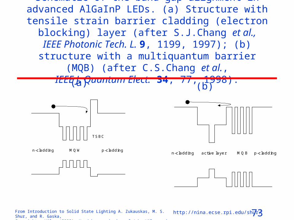
Schematic of the band gap alignment in advanced AlGaInP LEDs. (a) Structure with tensile strain barrier cladding
(electron blocking) layer (after S.J.Chang et al., IEEE Photonic Tech. L. 9, 1199, 1997); (b) structure with a
multiquantum barrier (MQB) (after C.S.Chang et al., IEEE J. Quantum Elect. 34, 77, 1998).
active layer MQB p-claddingn-cladding
MQW
TSBC
p-claddingn-cladding
(a) (b)

74From Introduction to Solid State Lighting A. Zukauskas, M. S. Shur, and R. Gaska, Copyright © Wiley (2002). Used by permission of John Wiley and Sons, Inc.
http://nina.ecse.rpi.edu/shur/
Schematic of band gap alignment in AlInGaN LEDs.
In0.23
Ga0.77
N
n-A
l 0.15
Ga 0.
85N
p-GaN
p-A
l 0.15
Ga 0.
85N
0.05 m
n-GaN
p-GaN
o
In0.45
Ga0.55
N
p-A
l 0.2G
a 0.8N
30 A
n-GaN
(a) (b)
(a) DH-based structure with two wide-band-gap cladding layers; radiative transitions occur between donor-acceptor pairs (after S.Nakamura et al., J. Appl. Phys. 76, 8189, 1994); (b) SQW structure with asymmetric confining layers; radiative transitions occur between quantum-confined levels of
electrons and holes (after S.Nakamura et al., Jpn. J. Appl. Phys. 34, L1332, 1995)
75From Introduction to Solid State Lighting A. Zukauskas, M. S. Shur, and R. Gaska, Copyright © Wiley (2002). Used by permission of John Wiley and Sons, Inc.
http://nina.ecse.rpi.edu/shur/
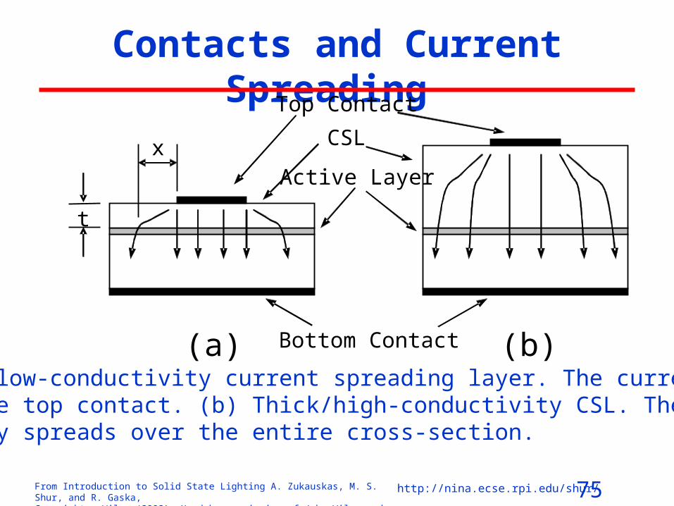
Contacts and Current Spreading
x
t
Top Contact
CSL Active Layer
Bottom Contact (a) (b)
a) Thin/low-conductivity current spreading layer. The current crowds under the top contact. (b) Thick/high-conductivity CSL. The current uniformly spreads over the entire cross-section.

76From Introduction to Solid State Lighting A. Zukauskas, M. S. Shur, and R. Gaska, Copyright © Wiley (2002). Used by permission of John Wiley and Sons, Inc.
http://nina.ecse.rpi.edu/shur/
Contact Geometries
100 m
250 m 350 m
(a) (b) (c) (d)
77From Introduction to Solid State Lighting A. Zukauskas, M. S. Shur, and R. Gaska, Copyright © Wiley (2002). Used by permission of John Wiley and Sons, Inc.
http://nina.ecse.rpi.edu/shur/
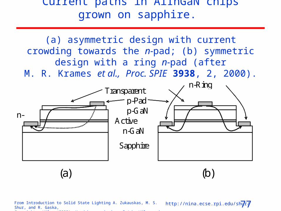
Current paths in AlInGaN chips grown on sapphire.
(a) asymmetric design with current crowding towards the n‑pad; (b) symmetric design with a ring n‑pad (after
M. R. Krames et al., Proc. SPIE 3938, 2, 2000).
p-GaN
n-GaN
Sapphire
p-Pad
n-Pad Active
Layer
n-Ring Pad
(a) (b)
Transparent Electrode

78From Introduction to Solid State Lighting A. Zukauskas, M. S. Shur, and R. Gaska, Copyright © Wiley (2002). Used by permission of John Wiley and Sons, Inc.
http://nina.ecse.rpi.edu/shur/
Emissive and Electrical Characteristics
350 400 450 500 550 600 650 700
AlInGaN SQWgreen (517nm)
AlGaAs DHred (649nm)
AlGaInP DHyellow (594nm)
AlInGaN SQW blue (465nm)
AlInGaN DHblue (427nm)
No
rmal
ized
Inte
nsity
(ar
b. u
nits
)
Wavelength (nm)

79From Introduction to Solid State Lighting A. Zukauskas, M. S. Shur, and R. Gaska, Copyright © Wiley (2002). Used by permission of John Wiley and Sons, Inc.
http://nina.ecse.rpi.edu/shur/
Emission line peak position vs. forward current in high brightness LEDs
1 10 100
450
500
550
600
650
AlInGaN blue
AlInGaN green
AlGaInP yellow
AlGaAs red
P
eak
Wav
ele
ngth
(nm
)
Forward Current (mA)

80From Introduction to Solid State Lighting A. Zukauskas, M. S. Shur, and R. Gaska, Copyright © Wiley (2002). Used by permission of John Wiley and Sons, Inc.
http://nina.ecse.rpi.edu/shur/
Output characteristics in AlGaAs, AlGaInP and AlInGaN-based
LEDs. Dependences are arbitrarily shifted along vertical axis
1 10 100
10-2
10-1
100
101
O
utpu
t Int
ensi
ty (
arb
. uni
ts)
Forward Current (mA)
AlGaAs red AlGaInP yellow AlInGaN green AlInGaN blue
81From Introduction to Solid State Lighting A. Zukauskas, M. S. Shur, and R. Gaska, Copyright © Wiley (2002). Used by permission of John Wiley and Sons, Inc.
http://nina.ecse.rpi.edu/shur/
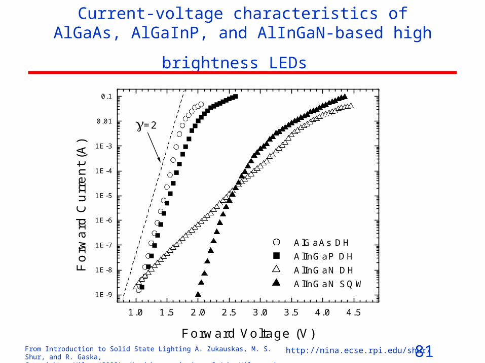
Current-voltage characteristics of AlGaAs, AlGaInP, and
AlInGaN-based high brightness LEDs
1.0 1.5 2.0 2.5 3.0 3.5 4.0 4.5
1E-9
1E-8
1E-7
1E-6
1E-5
1E-4
1E-3
0.01
0.1
=2
AlGaAs DH AlInGaP DH AlInGaN DH AlInGaN SQW
F
orw
ard
Cur
ren
t (A
)
Forward Voltage (V)
82From Introduction to Solid State Lighting A. Zukauskas, M. S. Shur, and R. Gaska, Copyright © Wiley (2002). Used by permission of John Wiley and Sons, Inc.
http://nina.ecse.rpi.edu/shur/
LIGHT EXTRACTION FROM LEDs

83From Introduction to Solid State Lighting A. Zukauskas, M. S. Shur, and R. Gaska, Copyright © Wiley (2002). Used by permission of John Wiley and Sons, Inc.
http://nina.ecse.rpi.edu/shur/
Challenges in light
extraction
absorbing substrate
ns
active layer
epoxy ne
c
(b)
Conventional LED chip grown on an absorbing substrate. the apex .
High-brightness LED chip design with thick transparent window layers. Light escapes through 6 cones
From A.Žukauskas et al., MRS Bull. 26, 764, 2001.
84From Introduction to Solid State Lighting A. Zukauskas, M. S. Shur, and R. Gaska, Copyright © Wiley (2002). Used by permission of John Wiley and Sons, Inc.
http://nina.ecse.rpi.edu/shur/
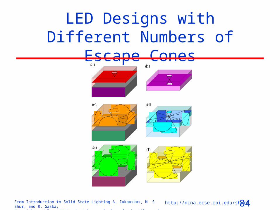
LED Designs with Different Numbers of Escape Cones
(a) (b)
(c) (d)
(e) (f)

85From Introduction to Solid State Lighting A. Zukauskas, M. S. Shur, and R. Gaska, Copyright © Wiley (2002). Used by permission of John Wiley and Sons, Inc.
http://nina.ecse.rpi.edu/shur/
Distributed Bragg Reflectors
n-Absorbing Substrate
n-DBR Structure
n-Electrode
n-Cladding Layer
p-Cladding Layer
p-Current Spreading Layer
p-Electrode
Active Layer
86From Introduction to Solid State Lighting A. Zukauskas, M. S. Shur, and R. Gaska, Copyright © Wiley (2002). Used by permission of John Wiley and Sons, Inc.
http://nina.ecse.rpi.edu/shur/
Absorption Losses and Photon Recycling • Most of the losses are due to the absorption in the active layer and in
the surrounding transparent cladding and window layers • The losses in the active layer depend on the probability of the light
reemission: absorbed photons can experience reincarnation and get a new chance to find the escape cone.
• If the internal quantum efficiency is high, the photon would be recycled many times until it escapes
• (Theory of the photon recycling in LEDs is discussed by T.Baba et al., Jpn. J. Appl. Phys. 35, 97, 1997 and references therein).

87From Introduction to Solid State Lighting A. Zukauskas, M. S. Shur, and R. Gaska, Copyright © Wiley (2002). Used by permission of John Wiley and Sons, Inc.
http://nina.ecse.rpi.edu/shur/
External Quantum Efficiency and Active Layer
• 72% external quantum efficiency was demonstrated in an optically pumped AlGaAs/GaAs double heterostructure mounted on a high-reflectivity surface (I. Schnitzer et al., Appl. Phys. Lett. 63, 2174, 1993).
• Multiple recycling of the photons was due to the internal quantum efficiency as high as 99.7%.
• In practical LEDs, the internal quantum efficiency is lower than 100% and the absorption in the active layer is often considered as parasitic. Therefore, thin active layers (homogenous or comprised of multiple wells) are often preferred.
• There is an optimum active layer thickness because of a trade-off between the active-layer reabsorption and electron confinement, and this thickness depends on the emission wavelength
• (Gardner et al., Appl. Phys. Lett. 74 (15), 2230, 1999).
88From Introduction to Solid State Lighting A. Zukauskas, M. S. Shur, and R. Gaska, Copyright © Wiley (2002). Used by permission of John Wiley and Sons, Inc.
http://nina.ecse.rpi.edu/shur/
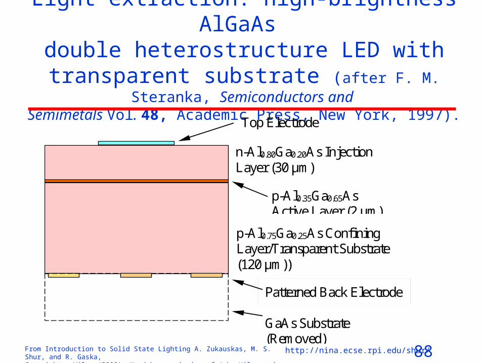
Light extraction: high-brightness AlGaAs double heterostructure LED with transparent
substrate (after F. M. Steranka, Semiconductors and Semimetals Vol. 48, Academic Press, New York, 1997).
GaAs Substrate (Removed)
Patterned Back Electrode
p-Al0.35Ga0.65As Active Layer (2 μm)
Top Electrode
n-Al0.80Ga0.20As Injection Layer (30 μm)
p-Al0.75Ga0.25As Confining Layer/Transparent Substrate (120 μm))

89From Introduction to Solid State Lighting A. Zukauskas, M. S. Shur, and R. Gaska, Copyright © Wiley (2002). Used by permission of John Wiley and Sons, Inc.
http://nina.ecse.rpi.edu/shur/
AlGaInP LEDs
(after F.A.Kish and R.M.Fletcher,
Semiconductors and Semimetals Vol. 48,
Academic Press, New York, 1997).
Wafer Bond
Back Electrode
Top Electrode
p-GaP Window Layer
n-GaP Wafer-Bonded Transparent Substrate 200 m
2 m
50 m
n-GaAs Substrate
AuGe/Au Back Electrode
AlGaInP DH
AuZn/Au Top Electrode
n-AlGaInP Current Blocking Layer
Distributed Bragg Refractor
200 m
10 m
7 m p-AlGaAs WL/CSL
p-GaAs Contact Layer a)
b)
AlGaInP DH
2 m

90From Introduction to Solid State Lighting A. Zukauskas, M. S. Shur, and R. Gaska, Copyright © Wiley (2002). Used by permission of John Wiley and Sons, Inc.
http://nina.ecse.rpi.edu/shur/
Progress in AlInGaP LEDs
After http://www.lumileds.com/technology/tutorial/slide2.htm

91From Introduction to Solid State Lighting A. Zukauskas, M. S. Shur, and R. Gaska, Copyright © Wiley (2002). Used by permission of John Wiley and Sons, Inc.
http://nina.ecse.rpi.edu/shur/
Sapphire Transparent Substrate
Ti/Al n-Electrode
n-GaN Contact Layer
Ni/Au p-Electrode
p-GaN Contact Layer
~100 m
4 m
0.15 m 0.5 m InGaN/AlGaN DH, SQW or MQW Structure
Transparent Metal (Au/Ni)
Buffer Layer
(after S.Nakamura and G.Fasol, The Blue Laser Diode: GaN Based Light Emitters and Lasers, Springer, Berlin, 1997).
Chip structure of AlInGaN/Al2O3 LED

92From Introduction to Solid State Lighting A. Zukauskas, M. S. Shur, and R. Gaska, Copyright © Wiley (2002). Used by permission of John Wiley and Sons, Inc.
http://nina.ecse.rpi.edu/shur/
AlInGaN/SiC LED (after J.A.Edmond et al., Proc. SPIE 3002, 2, 1997).
n-GaN Contact Layer
Ni Back Electrode
InGaN/AlGaN DH
Au Top Electrode p-GaN Contact Layer
n-SiC Transparent Substrate
Shorting Ring
Insulating Buffer Layer
93From Introduction to Solid State Lighting A. Zukauskas, M. S. Shur, and R. Gaska, Copyright © Wiley (2002). Used by permission of John Wiley and Sons, Inc.
http://nina.ecse.rpi.edu/shur/
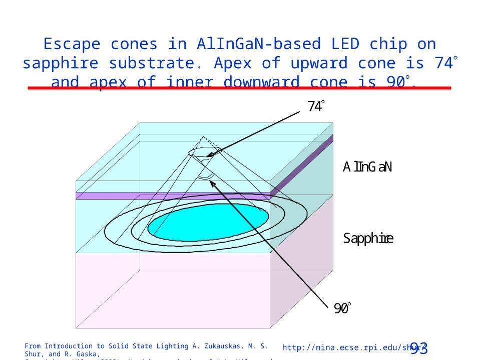
Escape cones in AlInGaN-based LED chip on sapphire substrate. Apex of upward cone is 74 and apex of inner downward cone is 90.
Sapphire
AlInGaN
90
74

94From Introduction to Solid State Lighting A. Zukauskas, M. S. Shur, and R. Gaska, Copyright © Wiley (2002). Used by permission of John Wiley and Sons, Inc.
http://nina.ecse.rpi.edu/shur/
High power AlInGaN Flip-Chip LED
InGaN/GaN Multiple Quantum Well
Sapphire
p-GaN Contact Layer
n-GaN Contact Layer
Submount
Solder
After J. J. Wieret et al., Appl. Phys. Lett. 78, 3379, 2001.

95From Introduction to Solid State Lighting A. Zukauskas, M. S. Shur, and R. Gaska, Copyright © Wiley (2002). Used by permission of John Wiley and Sons, Inc.
http://nina.ecse.rpi.edu/shur/
Shaped Chips: semi-spherical
Electroluminescent Structure
Au Coating
Antireflection Coating
Hemispherical Chip
Electroluminescent Structure Electrodes
a)
b)

96From Introduction to Solid State Lighting A. Zukauskas, M. S. Shur, and R. Gaska, Copyright © Wiley (2002). Used by permission of John Wiley and Sons, Inc.
http://nina.ecse.rpi.edu/shur/
Truncated-inverted-pyramid AlGaInP/GaP LED
p-GaP (55 μm)
AlGaInP Active Layer (~2 μm)
Wafer Bond
n-GaP (200 μm)
After M. R. Krames et al., Appl. Phys. Lett. 75, 2365, 1999.

97From Introduction to Solid State Lighting A. Zukauskas, M. S. Shur, and R. Gaska, Copyright © Wiley (2002). Used by permission of John Wiley and Sons, Inc.
http://nina.ecse.rpi.edu/shur/
Light Extraction : TIP-LEDs from LumiLeDs
Top contact
After M.O. HOLCOMB et al. (2001), Compound Semiconductor 7, 59, 2001).
high pressure sodium1 kWTIP-LED
StandardAlGaInP/GaP
1
100
10
1000
Peak wavelength (nm)
Lu
me
n/w
att
550 600 650 700 750
mercury vapor 1 kWfluorescent 1 W
tungsten 60 W
halogen 30 W
red f il teredtungsten 60 W
98From Introduction to Solid State Lighting A. Zukauskas, M. S. Shur, and R. Gaska, Copyright © Wiley (2002). Used by permission of John Wiley and Sons, Inc.
http://nina.ecse.rpi.edu/shur/
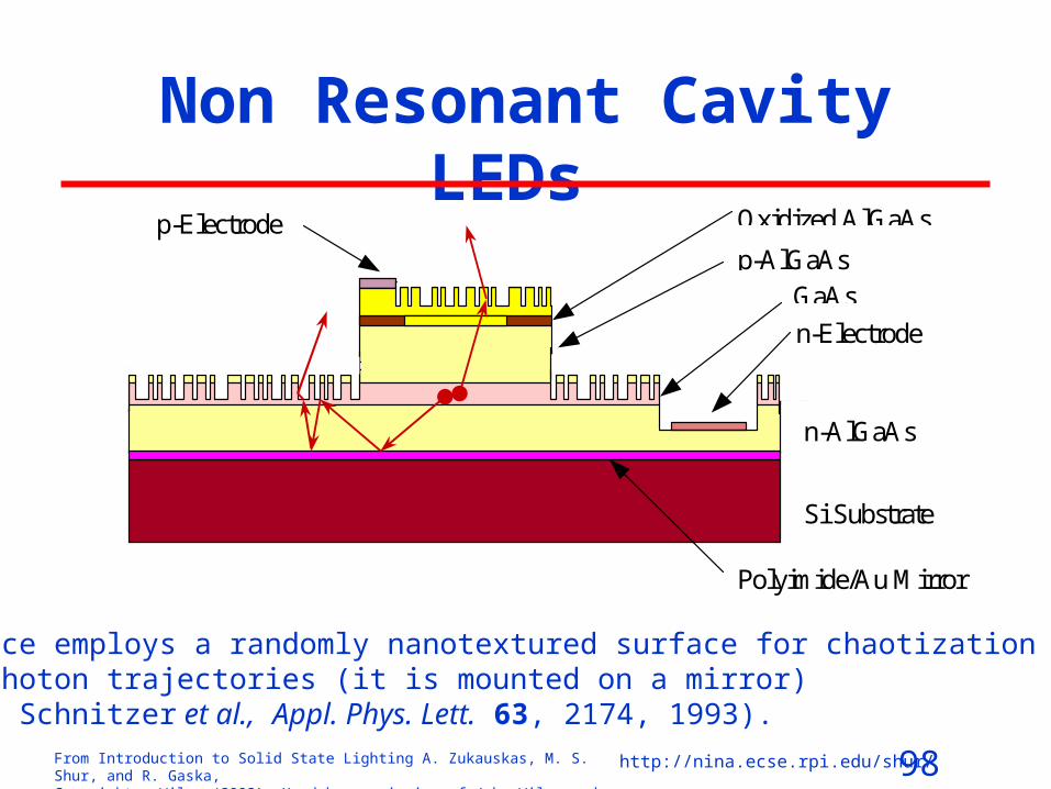
Non Resonant Cavity LEDs
Polyimide/Au Mirror
n-AlGaAs
Si Substrate
n-Electrode
GaAsp-AlGaAs
p-Electrode Oxidized AlGaAs
This device employs a randomly nanotextured surface for chaotization of the photon trajectories (it is mounted on a mirror)(after I. Schnitzer et al., Appl. Phys. Lett. 63, 2174, 1993).
99From Introduction to Solid State Lighting A. Zukauskas, M. S. Shur, and R. Gaska, Copyright © Wiley (2002). Used by permission of John Wiley and Sons, Inc.
http://nina.ecse.rpi.edu/shur/
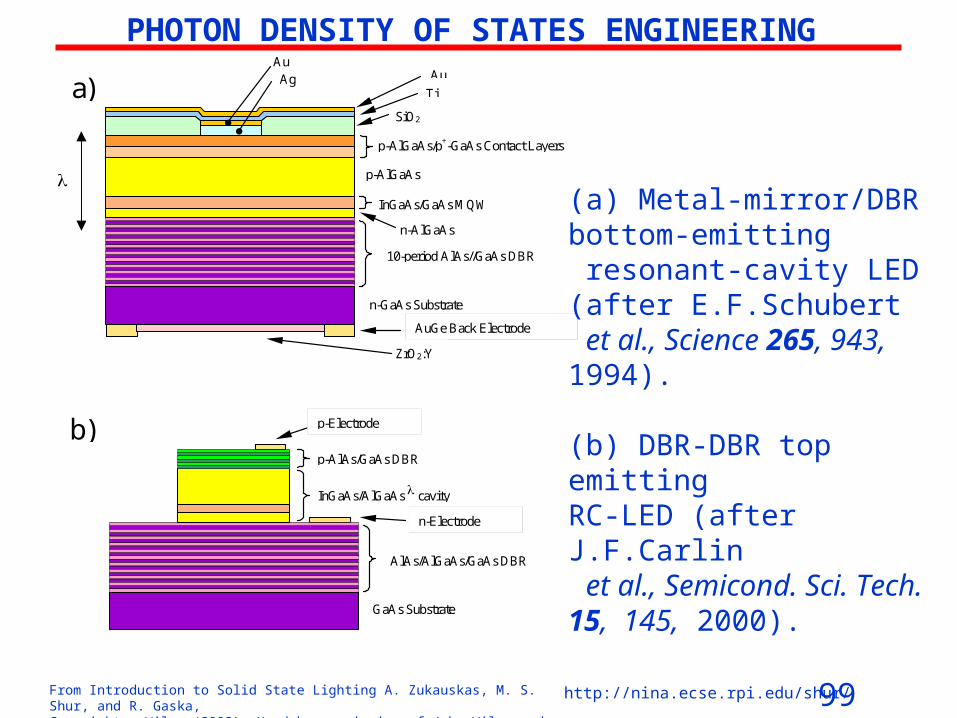
PHOTON DENSITY OF STATES ENGINEERING
n-GaAs Substrate
AuGe Back Electrode
SiO2
Au
n-AlGaAs
10-period AlAs//GaAs DBR
ZrO2:Y
AgAu
Ti
InGaAs/GaAs MQW
p-AlGaAs
p-AlGaAs/p+-GaAs Contact Layers
a)
GaAs Substrate
n-Electrode
AlAs/AlGaAs/GaAs DBR
InGaAs/AlGaAs cavity
p-AlAs/GaAs DBR
p-Electrodeb)
(a) Metal-mirror/DBR bottom-emitting resonant-cavity LED (after E.F.Schubert et al., Science 265, 943, 1994).
(b) DBR-DBR top emitting RC‑LED (after J.F.Carlin et al., Semicond. Sci. Tech. 15, 145, 2000).

100From Introduction to Solid State Lighting A. Zukauskas, M. S. Shur, and R. Gaska, Copyright © Wiley (2002). Used by permission of John Wiley and Sons, Inc.
http://nina.ecse.rpi.edu/shur/
Surface plasmon enhanced LED(after J.Vučković et al., IEEE J. Quantum Elect. 36, 1131,
2000).
Light emitting structure
Thin patterned silver layer
Si Substrate
Thick silver layer

101From Introduction to Solid State Lighting A. Zukauskas, M. S. Shur, and R. Gaska, Copyright © Wiley (2002). Used by permission of John Wiley and Sons, Inc.
http://nina.ecse.rpi.edu/shur/
Photonic Crystals(after J.D.Joannopoulos, Photonic Crystals: Molding
the Flow of Light, Princeton University Press, Princeton, N.J., 1995).
a) b) c)
102From Introduction to Solid State Lighting A. Zukauskas, M. S. Shur, and R. Gaska, Copyright © Wiley (2002). Used by permission of John Wiley and Sons, Inc.
http://nina.ecse.rpi.edu/shur/
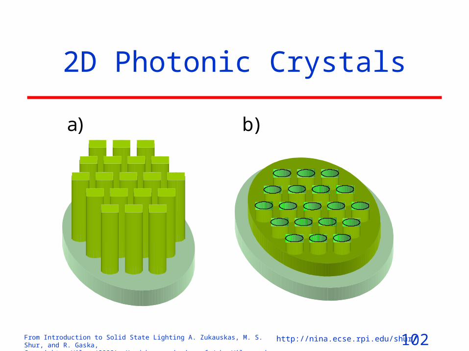
2D Photonic Crystals
a) b)

103From Introduction to Solid State Lighting A. Zukauskas, M. S. Shur, and R. Gaska, Copyright © Wiley (2002). Used by permission of John Wiley and Sons, Inc.
http://nina.ecse.rpi.edu/shur/
Semiconductor light-emitting device with 2D photonic crystal and DBR structure (after T.Baba,
IEEE J. Sel. Top. Quant. 3, 808, 1997 and S.Fan et al., Proc. SPIE 3002, 67, 1997).
DBR
2D Photonic Crystal
Active Region
104From Introduction to Solid State Lighting A. Zukauskas, M. S. Shur, and R. Gaska, Copyright © Wiley (2002). Used by permission of John Wiley and Sons, Inc.
http://nina.ecse.rpi.edu/shur/
WHITE SOLID-STATE
LAMP

105From Introduction to Solid State Lighting A. Zukauskas, M. S. Shur, and R. Gaska, Copyright © Wiley (2002). Used by permission of John Wiley and Sons, Inc.
http://nina.ecse.rpi.edu/shur/
CRI for White Light
Spectral Range Temperature (K) Efficacy (lm/W) General CRI
2856 17 100 4870 79 100
Full (Planckian)
6504 95 100 2856 154 100 4870 196 100
380 nm-780 nm (trimmed-Planckian) 6504 193 100
2856 334 95 4870 320 95
430 nm-660 nm (trimmed-Planckian) 6504 305 95
,λdλSλdλSλVK
0
780
380
Wlm683
106From Introduction to Solid State Lighting A. Zukauskas, M. S. Shur, and R. Gaska, Copyright © Wiley (2002). Used by permission of John Wiley and Sons, Inc.
http://nina.ecse.rpi.edu/shur/
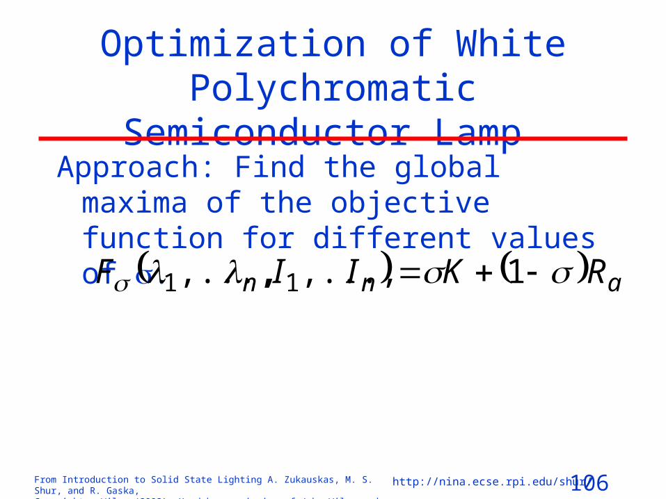
Optimization of White Polychromatic Semiconductor Lamp
Approach: Find the global maxima of the objective function for different values of .
ann RKIIF 1,...,,,..., 11

107From Introduction to Solid State Lighting A. Zukauskas, M. S. Shur, and R. Gaska, Copyright © Wiley (2002). Used by permission of John Wiley and Sons, Inc.
http://nina.ecse.rpi.edu/shur/
Phase distribution for a dichromatic white lamp with the 30‑nm line width of the primary sources and 4870 K color
temperature (after Žukauskas et al., Appl. Phys. Lett. 80, 2002).
0 100 200 300 400
-60
-40
-20
0
20
380/569 nm
489/591 nm
496/635 nm
481/580 nm
450/571 nmRa
K (lm/W)

108From Introduction to Solid State Lighting A. Zukauskas, M. S. Shur, and R. Gaska, Copyright © Wiley (2002). Used by permission of John Wiley and Sons, Inc.
http://nina.ecse.rpi.edu/shur/
Optimal boundaries of the phase distribution for 4870‑K white-light sources containing 2, 3, 4, and 5 primary sources with the 30‑nm line widths (after Žukauskas et al., Appl. Phys. Lett. 80, 2002). Crosses mark the points that are suggested for
highest reasonable CRI for each number of the primary sources.
320 340 360 380 400 420 440
5
10
20
30
405060
70
80
90
95
98
9999.5R
a
54
3
2
Systems: quintichromatic quadrichromatic trichromatic dichromatic
K (lm/W)

109From Introduction to Solid State Lighting A. Zukauskas, M. S. Shur, and R. Gaska, Copyright © Wiley (2002). Used by permission of John Wiley and Sons, Inc.
http://nina.ecse.rpi.edu/shur/
InGaN based luminescence conversion white LED (after S.Nakamura and G.Fasol, The Blue Laser Diode: GaN
Based Light Emitters and Lasers, Springer, Berlin, 1997)
InGaN chip
Phosphor layer

110From Introduction to Solid State Lighting A. Zukauskas, M. S. Shur, and R. Gaska, Copyright © Wiley (2002). Used by permission of John Wiley and Sons, Inc.
http://nina.ecse.rpi.edu/shur/
Energy levels of Ce3+ (4f1) in yttrium aluminum garnet Y3Al5O12 (after M.Batenschuk et al., MRS Symp. Proc. 560, 215, 1999).
2F
7/24f
1(5s
25p
6)
5d1(5s
25p
6)
Y3Al
5O
12:Ce3+(4f1)
(0/+)
52
0
46
0
58
0
2F
5/2
2D 5.1 eV
6.0 eV
7.0 eV
8.0 eV8.6 eV
VB
CB
2.4 eV
0 eV
6.2 eV
111From Introduction to Solid State Lighting A. Zukauskas, M. S. Shur, and R. Gaska, Copyright © Wiley (2002). Used by permission of John Wiley and Sons, Inc.
http://nina.ecse.rpi.edu/shur/
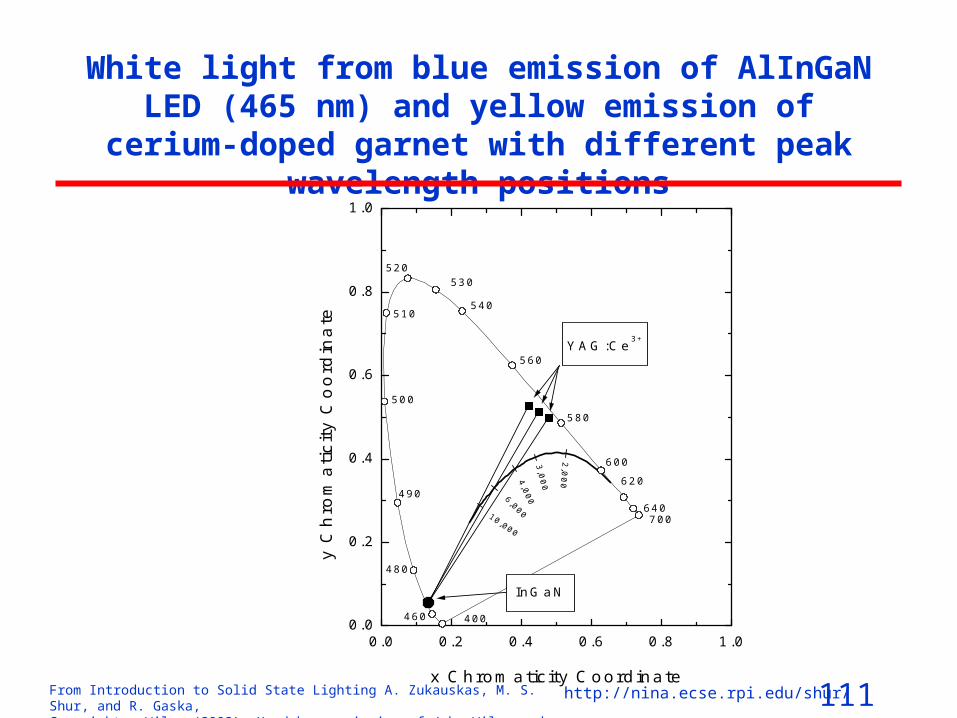
White light from blue emission of AlInGaN LED (465 nm) and yellow emission of cerium-doped garnet with
different peak wavelength positions
0.0 0.2 0.4 0.6 0.8 1.00.0
0.2
0.4
0.6
0.8
1.0
YAG:Ce3+
InGaN
10,000
6,000
4,0
00
3,0
00
2,0
00
460
640700
620
600
580
560
540
530520
510
500
490
480
400
y C
hro
ma
tic
ity
Co
ord
ina
te
x Chromaticity Coordinate
112From Introduction to Solid State Lighting A. Zukauskas, M. S. Shur, and R. Gaska, Copyright © Wiley (2002). Used by permission of John Wiley and Sons, Inc.
http://nina.ecse.rpi.edu/shur/
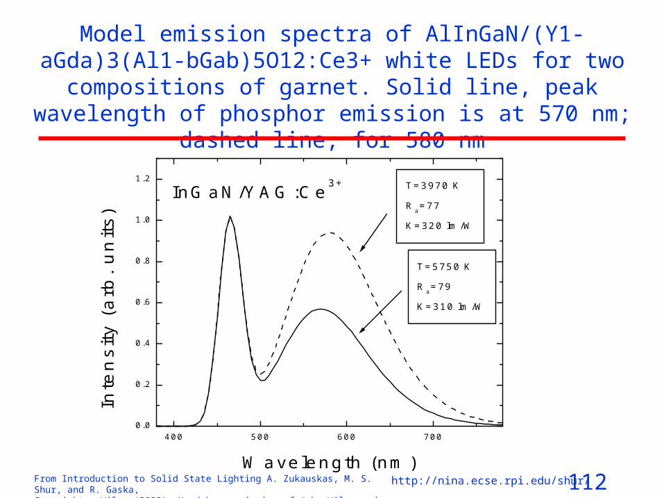
Model emission spectra of AlInGaN/(Y1-aGda)3(Al1‑bGab)5O12:Ce3+ white LEDs for two compositions of garnet. Solid line, peak wavelength
of phosphor emission is at 570 nm; dashed line, for 580 nm
400 500 600 7000.0
0.2
0.4
0.6
0.8
1.0
1.2
InGaN/YAG:Ce3+ T=3970 K
Ra=77
K=320 lm/W
Wavelength (nm)
Inte
ns
ity (
arb
. u
nits
)
T=5750 K
Ra=79
K=310 lm/W
113From Introduction to Solid State Lighting A. Zukauskas, M. S. Shur, and R. Gaska, Copyright © Wiley (2002). Used by permission of John Wiley and Sons, Inc.
http://nina.ecse.rpi.edu/shur/
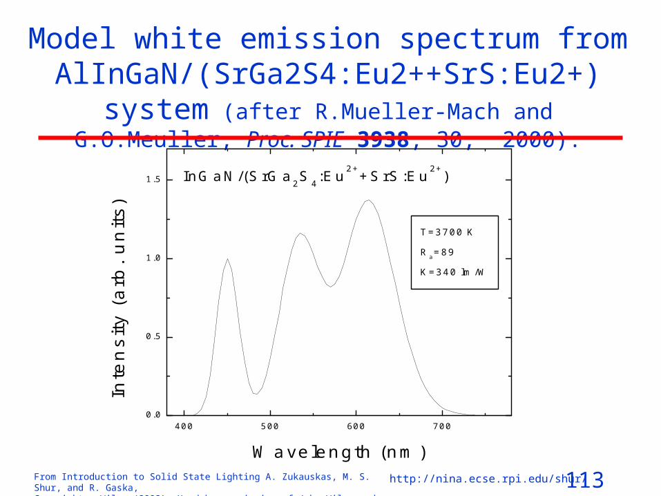
Model white emission spectrum from AlInGaN/(SrGa2S4:Eu2++SrS:Eu2+) system (after R.Mueller-Mach and G.O.Meuller, Proc. SPIE 3938, 30, 2000).
400 500 600 7000.0
0.5
1.0
1.5 InGaN/(SrGa2S4:Eu2+
+SrS:Eu2+
)
T=3700 K
Ra=89
K=340 lm/W
Wavelength (nm)
Inte
ns
ity
(a
rb.
un
its
)
114From Introduction to Solid State Lighting A. Zukauskas, M. S. Shur, and R. Gaska, Copyright © Wiley (2002). Used by permission of John Wiley and Sons, Inc.
http://nina.ecse.rpi.edu/shur/
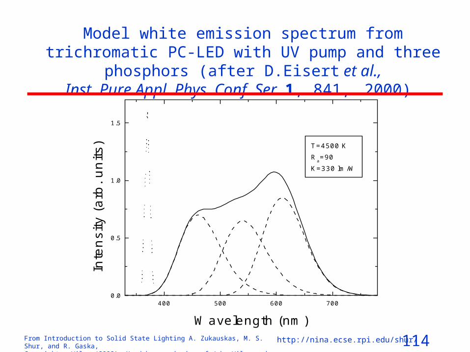
Model white emission spectrum from trichromatic PC‑LED with UV pump and three phosphors (after D.Eisert et al.,
Inst. Pure Appl. Phys. Conf. Ser. 1, 841, 2000).
400 500 600 7000.0
0.5
1.0
1.5
T=4500 KR
a=90
K=330 lm/W
Wavelength (nm)
Inte
nsi
ty (
arb
. un
its)

115From Introduction to Solid State Lighting A. Zukauskas, M. S. Shur, and R. Gaska, Copyright © Wiley (2002). Used by permission of John Wiley and Sons, Inc.
http://nina.ecse.rpi.edu/shur/
MULTICHIP LED: 2 chip LEDs
Wavelength (nm)/Intensity Color Temperature
(K) 1 /I1 2 /I2
K (lm/W) Ra
2856 450/0.157 580/0.843 492 -13 4870 450/0.325 572/0.675 430 3.0 6504 450/0.399 569/0.601 393 9.5

116From Introduction to Solid State Lighting A. Zukauskas, M. S. Shur, and R. Gaska, Copyright © Wiley (2002). Used by permission of John Wiley and Sons, Inc.
http://nina.ecse.rpi.edu/shur/
Optimized spectral power distributions
400 450 500 550 600 650
K=430 lm/WR
a=3
Pow
er (
arb.
uni
ts)
Wavelength (nm)
K=366 lm/WR
a=85
K=332 lm/WR
a=98
K=324 lm/WR
a=99
2 LEDs
3 LEDs
4 LEDs
5 LEDsAfter A.Žukauskas et al., Appl. Phys. Lett. 80, 2002.
117From Introduction to Solid State Lighting A. Zukauskas, M. S. Shur, and R. Gaska, Copyright © Wiley (2002). Used by permission of John Wiley and Sons, Inc.
http://nina.ecse.rpi.edu/shur/
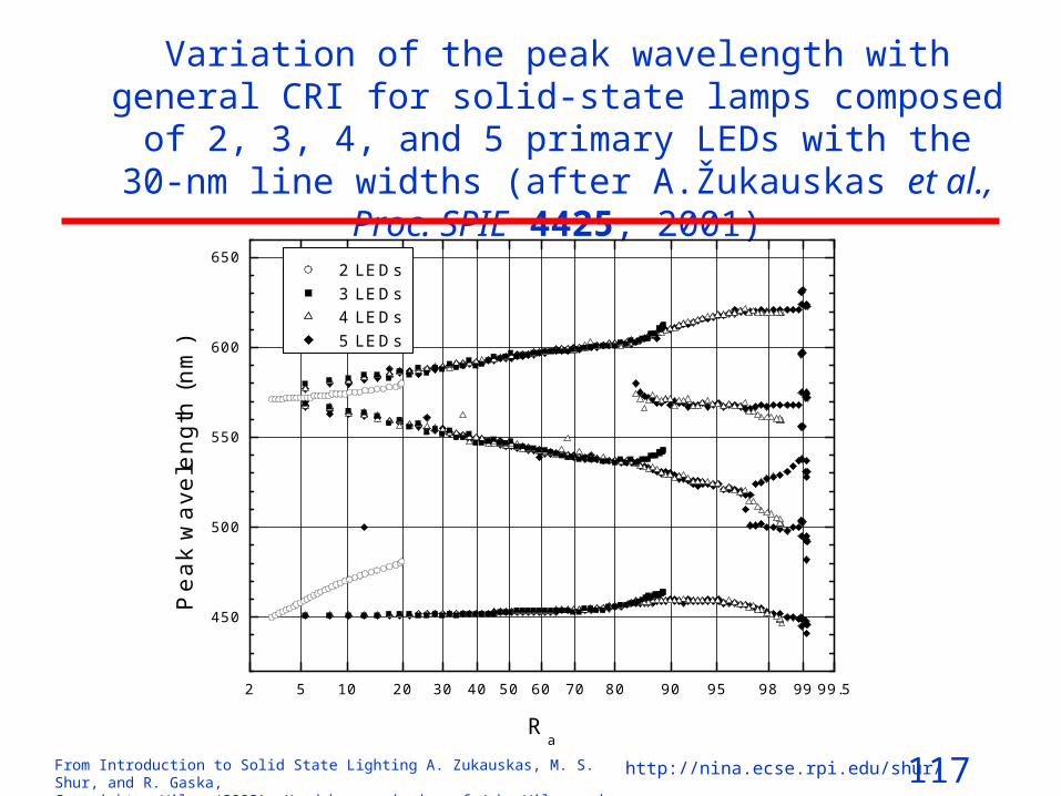
Variation of the peak wavelength with general CRI for solid-state lamps composed of 2, 3, 4, and 5 primary LEDs with the 30‑nm line widths (after A.Žukauskas et al., Proc. SPIE 4425, 2001)
2 5 10 20 30 40 50 60 70 80 90 95 98 99 99.5
450
500
550
600
650 2 LEDs 3 LEDs 4 LEDs 5 LEDs
Pe
ak
wa
vele
ng
th (
nm
)
Ra

118From Introduction to Solid State Lighting A. Zukauskas, M. S. Shur, and R. Gaska, Copyright © Wiley (2002). Used by permission of John Wiley and Sons, Inc.
http://nina.ecse.rpi.edu/shur/
Nichia LED CharacteristicsColor DC VoltageVF[V] IR[µA] PO[mW] Chromaticity Coordinates*
x y
Typ. Max. Max. Typ. Typ. Typ.
BLUE 3.6 4.0 50.0 6 0.130 0.075
GREEN 3.5 4.0 50.0 4 0.170 0.700
RED 1.9 2.4 50.0 2 0.700 0.300
WHITE 3.6 4.0 50.0 (4) 0.310 0.320
Condition IF=20mA VR = 5V
*The CIE standard colorimetric system
After http://www.nichia.co.jp/lamp-e.htm (updated June 2000)
Newer data: Dr. Zulauskas measurements: 17 mW for blue and 7 mW for green
119From Introduction to Solid State Lighting A. Zukauskas, M. S. Shur, and R. Gaska, Copyright © Wiley (2002). Used by permission of John Wiley and Sons, Inc.
http://nina.ecse.rpi.edu/shur/
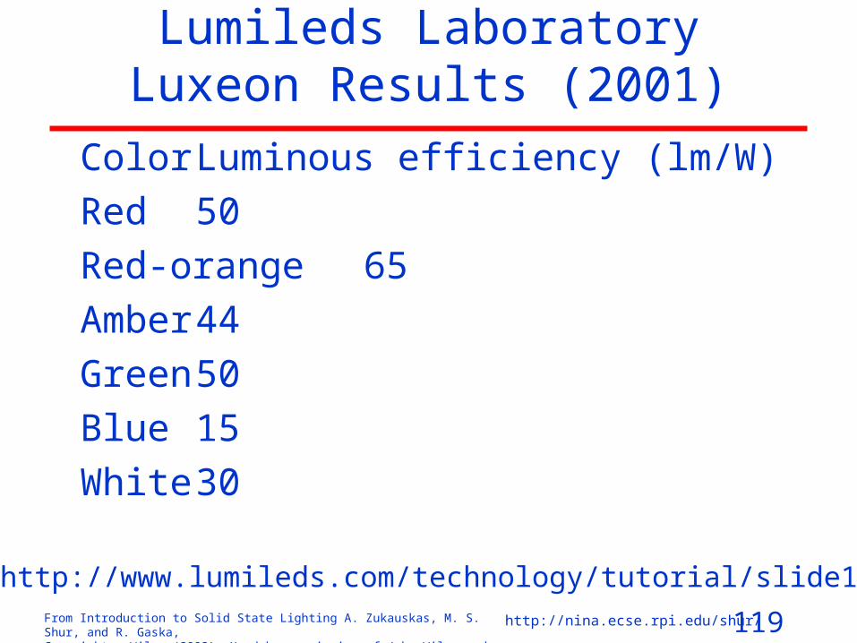
Lumileds Laboratory Luxeon Results (2001)
Color Luminous efficiency (lm/W)
Red 50
Red-orange 65
Amber 44
Green 50
Blue 15
White 30
After http://www.lumileds.com/technology/tutorial/slide14.htm
120From Introduction to Solid State Lighting A. Zukauskas, M. S. Shur, and R. Gaska, Copyright © Wiley (2002). Used by permission of John Wiley and Sons, Inc.
http://nina.ecse.rpi.edu/shur/
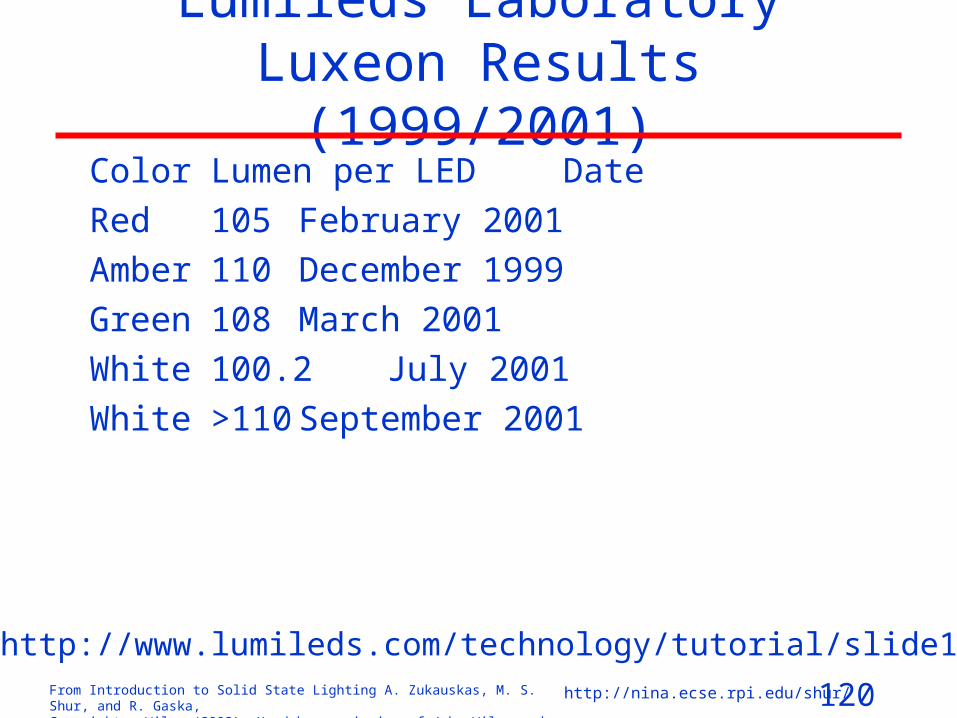
Lumileds Laboratory Luxeon Results (1999/2001)
Color Lumen per LED Date
Red 105 February 2001
Amber 110 December 1999
Green 108 March 2001
White 100.2 July 2001
White >110 September 2001
After http://www.lumileds.com/technology/tutorial/slide15.htm

121From Introduction to Solid State Lighting A. Zukauskas, M. S. Shur, and R. Gaska, Copyright © Wiley (2002). Used by permission of John Wiley and Sons, Inc.
http://nina.ecse.rpi.edu/shur/
LED Applications

122From Introduction to Solid State Lighting A. Zukauskas, M. S. Shur, and R. Gaska, Copyright © Wiley (2002). Used by permission of John Wiley and Sons, Inc.
http://nina.ecse.rpi.edu/shur/
LED Applications Signals and Displays
•POWER SIGNALS•Traffic Lights•Automotive Signage•Miscellaneous Signage
•DISPLAYS•Alphanumeric Displays•Full Color Video Displays

123From Introduction to Solid State Lighting A. Zukauskas, M. S. Shur, and R. Gaska, Copyright © Wiley (2002). Used by permission of John Wiley and Sons, Inc.
http://nina.ecse.rpi.edu/shur/
LED Power Signal (after D.L.Evans,
Proc. SPIE 3002, 142, 1997).
Moisture seal
Housing
Housing gasket
Cover lens
LED assembly
Standard connectors
Secondary opticsDrive electronics

124From Introduction to Solid State Lighting A. Zukauskas, M. S. Shur, and R. Gaska, Copyright © Wiley (2002). Used by permission of John Wiley and Sons, Inc.
http://nina.ecse.rpi.edu/shur/
Vehicle Light Signal
After D.Decker, Automot. Eng. Int. 108, 62, 2000.

125From Introduction to Solid State Lighting A. Zukauskas, M. S. Shur, and R. Gaska, Copyright © Wiley (2002). Used by permission of John Wiley and Sons, Inc.
http://nina.ecse.rpi.edu/shur/
Pixels for Displays
B B
G
R R
R G
G
B
R G R G
B
R G

126From Introduction to Solid State Lighting A. Zukauskas, M. S. Shur, and R. Gaska, Copyright © Wiley (2002). Used by permission of John Wiley and Sons, Inc.
http://nina.ecse.rpi.edu/shur/
LED Applications (Biomedical)• MEDICAL APPLICATIONS
– Phototherapy of Neonatal Jaundice– Photodynamic Therapy– Photopolymerization of Dental Composites– Phototherapy of Seasonal Affective Disorder
• PHOTOSYNTHESIS– Plant Growing– Photobioreactors
• OPTICAL MEASUREMENTS– Fluorescent Sensors– Time-Domain and Frequency-Domain Spectroscopy– Other Optical Applications
127From Introduction to Solid State Lighting A. Zukauskas, M. S. Shur, and R. Gaska, Copyright © Wiley (2002). Used by permission of John Wiley and Sons, Inc.
http://nina.ecse.rpi.edu/shur/
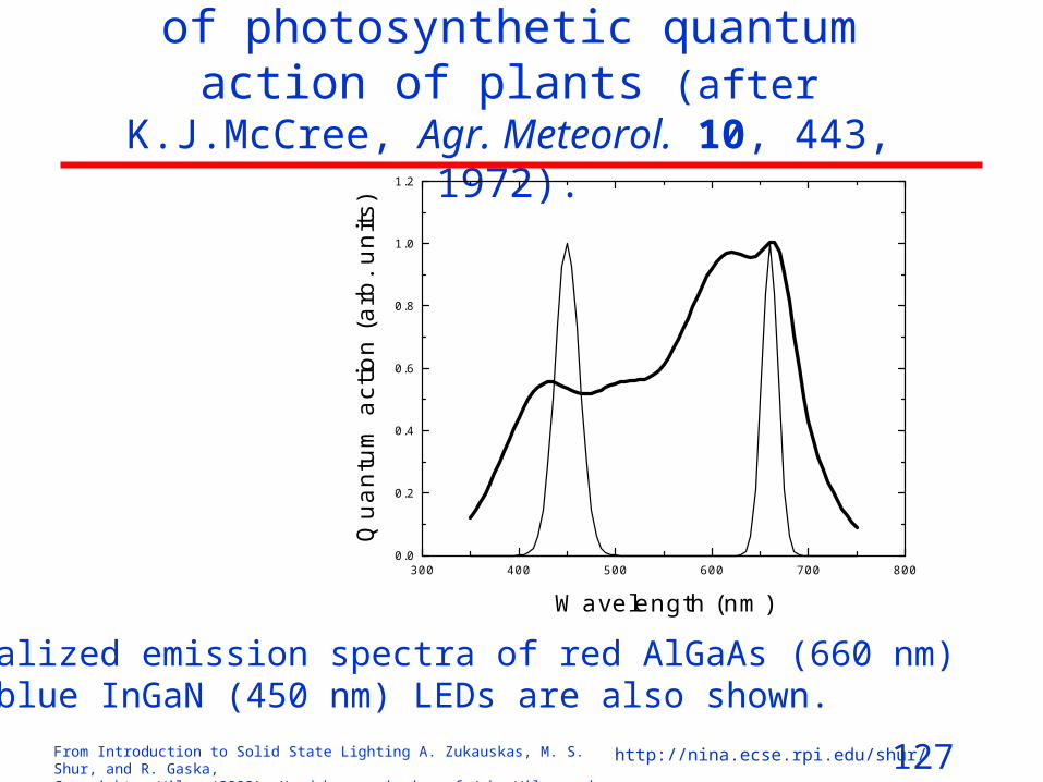
Schematic spectrum of photosynthetic quantum action of plants (after K.J.McCree, Agr. Meteorol. 10, 443, 1972).
300 400 500 600 700 8000.0
0.2
0.4
0.6
0.8
1.0
1.2
Wavelength (nm)
Qu
an
tum
act
ion
(a
rb.
un
its)
Normalized emission spectra of red AlGaAs (660 nm) and blue InGaN (450 nm) LEDs are also shown.

128From Introduction to Solid State Lighting A. Zukauskas, M. S. Shur, and R. Gaska, Copyright © Wiley (2002). Used by permission of John Wiley and Sons, Inc.
http://nina.ecse.rpi.edu/shur/
LED-based photobioreactor (after C.‑G.Lee and B.Ø.Palsson, Biotechnol. Bioeng. 44, 1161, 1994)
LED Illumination
Chamber
Gas Control
Unit
New Medium
Waste
Ultra-Filtration
Unit
Liquid/Gas
Separator
Circulation Pump

129From Introduction to Solid State Lighting A. Zukauskas, M. S. Shur, and R. Gaska, Copyright © Wiley (2002). Used by permission of John Wiley and Sons, Inc.
http://nina.ecse.rpi.edu/shur/
LED Applications - Lighting
• ILLUMINATION– Local Illumination– General Lighting
Cone Reflector
Parabolic Reflector
Fresnel Lens
LED array
LED Floodlight (after A.García‑Botella et al., J. IES 29, 135, 2000)

130From Introduction to Solid State Lighting A. Zukauskas, M. S. Shur, and R. Gaska, Copyright © Wiley (2002). Used by permission of John Wiley and Sons, Inc.
http://nina.ecse.rpi.edu/shur/
Cross-section of a LED fiber light engine (after M. R. Krames et al., Proc. SPIE 3938, 2, 2000).
Electronics
Driver
Optics
Housing
LED Array
Fiber Interface

131From Introduction to Solid State Lighting A. Zukauskas, M. S. Shur, and R. Gaska, Copyright © Wiley (2002). Used by permission of John Wiley and Sons, Inc.
http://nina.ecse.rpi.edu/shur/
SOME of LED WEB SITES
• http://www.misty.com/people/don/led.html• http://www.luxeon.com/index.html• http://ledmuseum.home.att.net/• http://www.nichia.com/• http://www.cree.com/• http://www.s-et.com• http://www.oida.org/• http://safeco2.home.att.net/laser.htm

132From Introduction to Solid State Lighting A. Zukauskas, M. S. Shur, and R. Gaska, Copyright © Wiley (2002). Used by permission of John Wiley and Sons, Inc.
http://nina.ecse.rpi.edu/shur/
Conclusion
“... it is vital to know that the LED is an ultimate form of lamp, in principle and in practice, and that its development indeed can and will continue until all power levels and colors are realized.”
HOLONYAK, N., JR. (2000), “Is the light emitting diode (LED) an ultimate lamp?” Am. J. Phys. 68 (9), pp. 864-866.