Embed Size (px)
Citation preview

1
Feedback
Microelectronic Circuits - Fifth Edition Sedra/Smith 2Copyright 2004 by Oxford University Press, Inc.
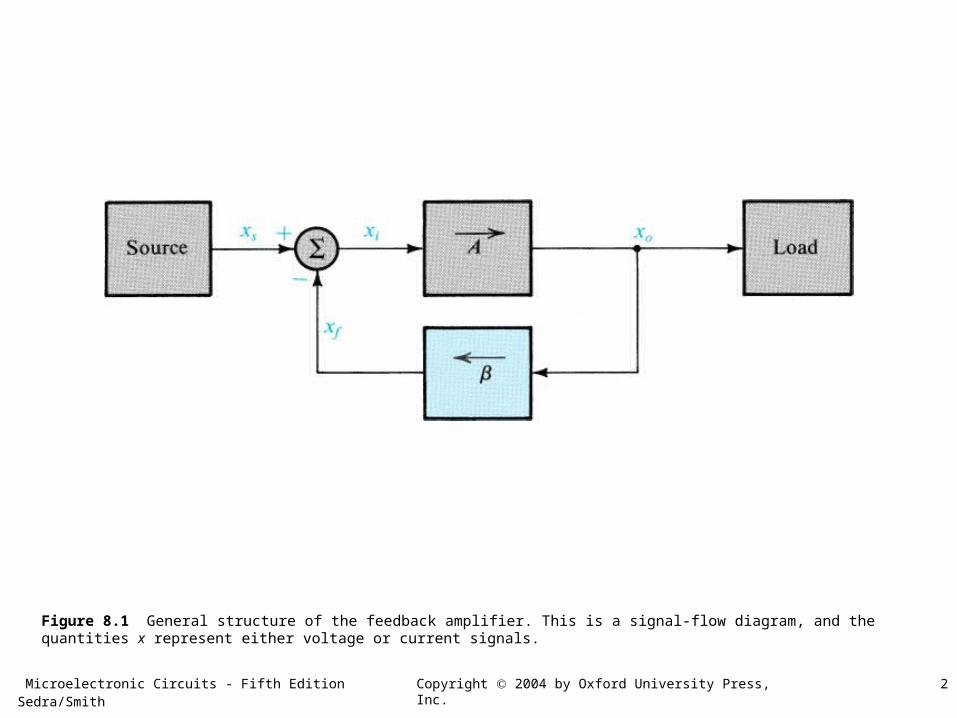
Figure 8.1 General structure of the feedback amplifier. This is a signal-flow diagram, and the quantities x represent either voltage or current signals.
Microelectronic Circuits - Fifth Edition Sedra/Smith 3Copyright 2004 by Oxford University Press, Inc.
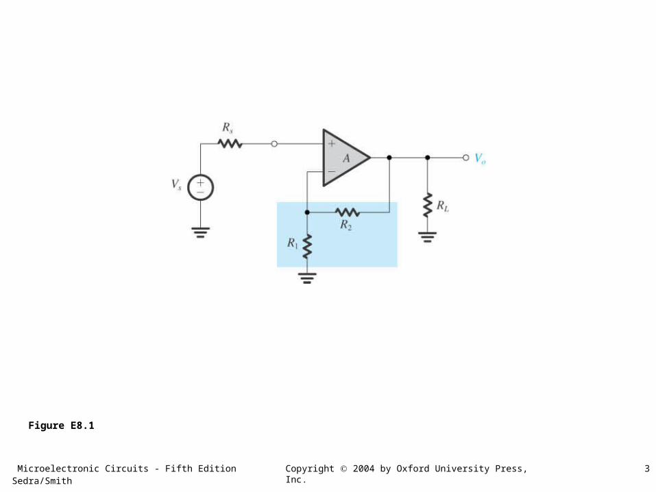
Figure E8.1
Microelectronic Circuits - Fifth Edition Sedra/Smith 4Copyright 2004 by Oxford University Press, Inc.
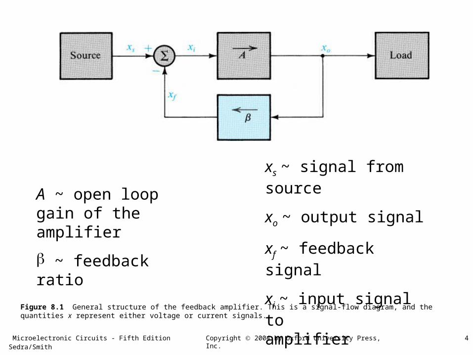
Figure 8.1 General structure of the feedback amplifier. This is a signal-flow diagram, and the quantities x represent either voltage or current signals.
A ~ open loop gain of the amplifier
~ feedback ratio
xs ~ signal from source
xo ~ output signal
xf ~ feedback signal
xi ~ input signal to amplifier
Microelectronic Circuits - Fifth Edition Sedra/Smith 5Copyright 2004 by Oxford University Press, Inc.
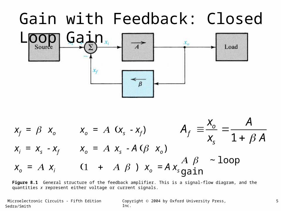
Figure 8.1 General structure of the feedback amplifier. This is a signal-flow diagram, and the quantities x represent either voltage or current signals.
xf = xo
xi = xs - xf
xo = xi
xo = xs - xf)
xo = xs - A xo)
)xo = A xs
1o
fs
x AA
x A
Gain with Feedback: Closed Loop Gain
~ loop gain
Microelectronic Circuits - Fifth Edition Sedra/Smith 6Copyright 2004 by Oxford University Press, Inc.
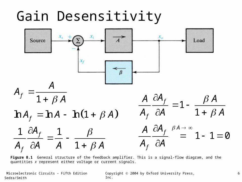
Figure 8.1 General structure of the feedback amplifier. This is a signal-flow diagram, and the quantities x represent either voltage or current signals.
1
ln ln ln 1
1 1
1
f
f
f
f
AA
A
A A A
A
A A A A
Gain Desensitivity
11
1 1 0
f
f
Af
f
AA A
A A A
AA
A A
Microelectronic Circuits - Fifth Edition Sedra/Smith 7Copyright 2004 by Oxford University Press, Inc.
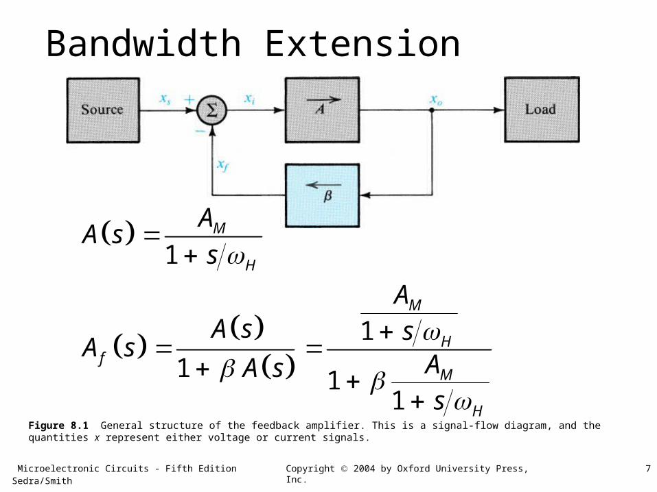
Figure 8.1 General structure of the feedback amplifier. This is a signal-flow diagram, and the quantities x represent either voltage or current signals.
1
1
1 11
M
H
M
Hf
M
H
AA s
s
AA s s
A sAA ss
Bandwidth Extension
Microelectronic Circuits - Fifth Edition Sedra/Smith 8Copyright 2004 by Oxford University Press, Inc.
Figure 8.1 General structure of the feedback amplifier. This is a signal-flow diagram, and the quantities x represent either voltage or current signals.
1
111
1
1 1
M
H Mf
M H M
H
M Mf
H M
As A
A sA s As
A AA s
s A
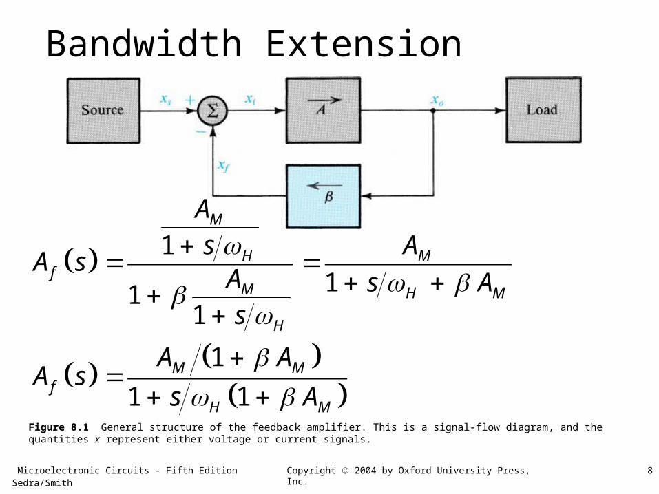
Bandwidth Extension
Microelectronic Circuits - Fifth Edition Sedra/Smith 9Copyright 2004 by Oxford University Press, Inc.
Figure 8.1 General structure of the feedback amplifier. This is a signal-flow diagram, and the quantities x represent either voltage or current signals.
1
1 1 1
~ closed loop midband gain1
1 ~ closed loop bandwidth
closed loopM Mf
H M
closed loop
Mclosed loop
M
closed loop H M
GA AA s
ss AB
AG
A
B A
Bandwidth Extension
Microelectronic Circuits - Fifth Edition Sedra/Smith 10Copyright 2004 by Oxford University Press, Inc.
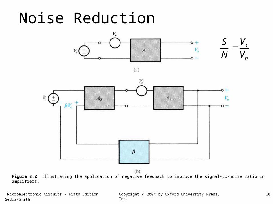
Figure 8.2 Illustrating the application of negative feedback to improve the signal-to-noise ratio in amplifiers.
Noise Reduction
s
n
VS
N V
Microelectronic Circuits - Fifth Edition Sedra/Smith 11Copyright 2004 by Oxford University Press, Inc.
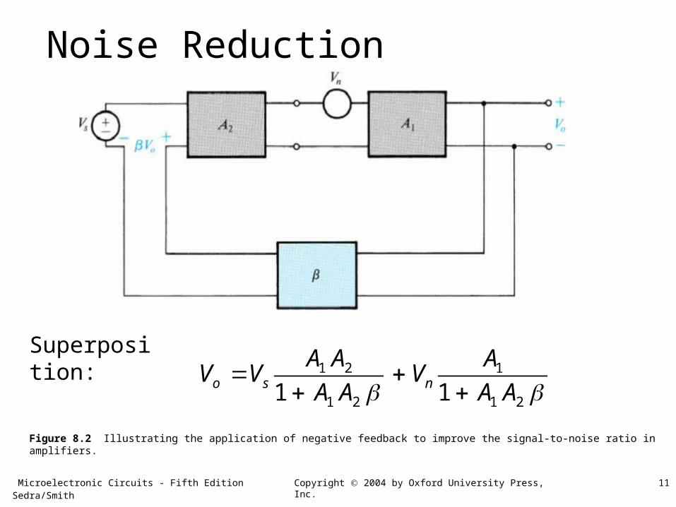
Figure 8.2 Illustrating the application of negative feedback to improve the signal-to-noise ratio in amplifiers.
Noise Reduction
1 2 1
1 2 1 21 1o s n
A A AV V V
A A A A
Superposition:
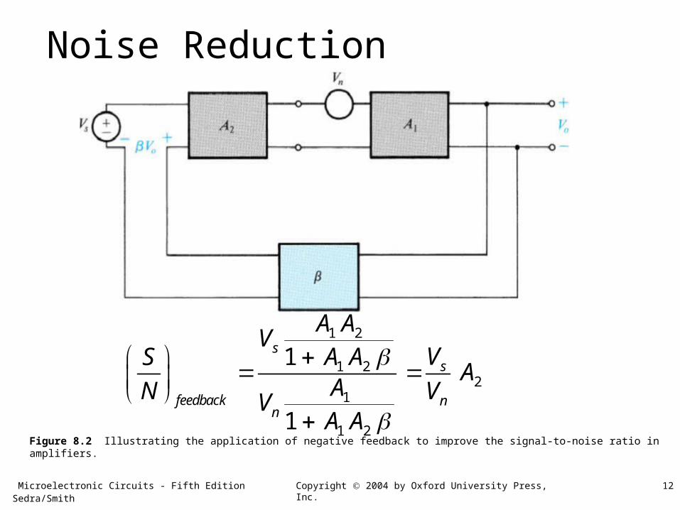
Microelectronic Circuits - Fifth Edition Sedra/Smith 12Copyright 2004 by Oxford University Press, Inc.
Figure 8.2 Illustrating the application of negative feedback to improve the signal-to-noise ratio in amplifiers.
Noise Reduction
1 2
1 22
1
1 2
1
1
ss
feedback nn
A AV
VA ASA
AN VVA A
Microelectronic Circuits - Fifth Edition Sedra/Smith 13Copyright 2004 by Oxford University Press, Inc.
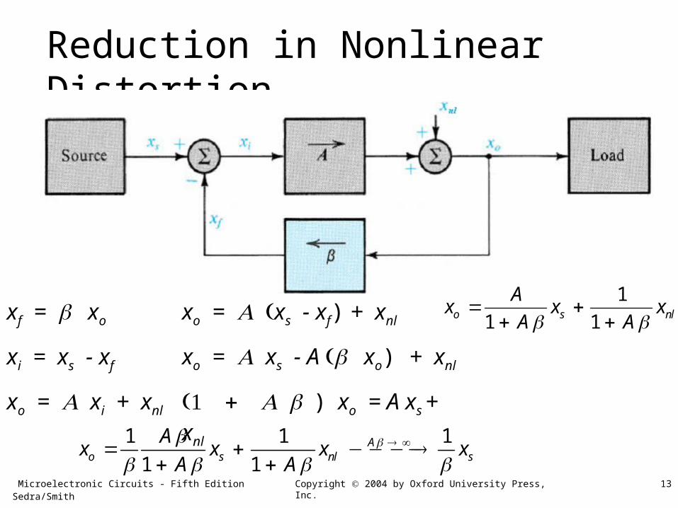
Reduction in Nonlinear Distortion
xf = xo
xi = xs - xf
xo = xi + xnl
xo = xs - xf) + xnl
xo = xs - A xo) + xnl
)xo = A xs + xnl
1
1 1o s nl
Ax x x
A A
1 1 1
1 1A
o s nl s
Ax x x x
A A
Microelectronic Circuits - Fifth Edition Sedra/Smith 14Copyright 2004 by Oxford University Press, Inc.
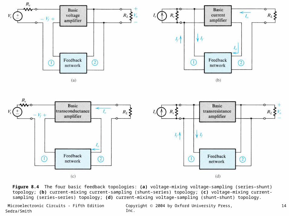
Figure 8.4 The four basic feedback topologies: (a) voltage-mixing voltage-sampling (series–shunt) topology; (b) current-mixing current-sampling (shunt–series) topology; (c) voltage-mixing current-sampling (series–series) topology; (d) current-mixing voltage-sampling (shunt–shunt) topology.
Microelectronic Circuits - Fifth Edition Sedra/Smith 15Copyright 2004 by Oxford University Press, Inc.
Effects of Negative Feedback on Input and Output Impedances
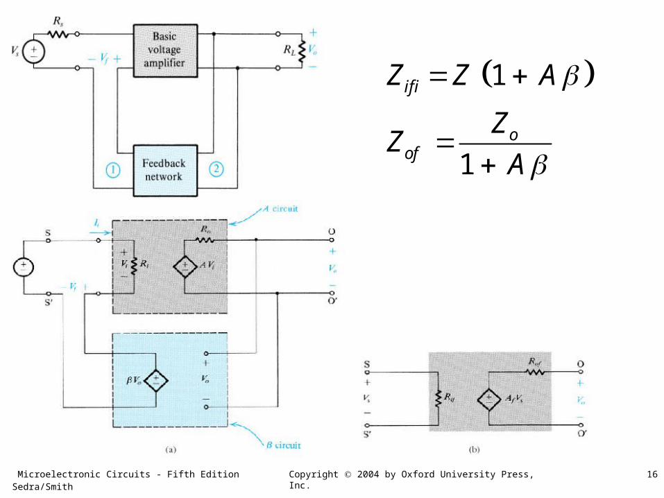
Microelectronic Circuits - Fifth Edition Sedra/Smith 16Copyright 2004 by Oxford University Press, Inc.
1
1
if i
oof
Z Z A
ZZ
A
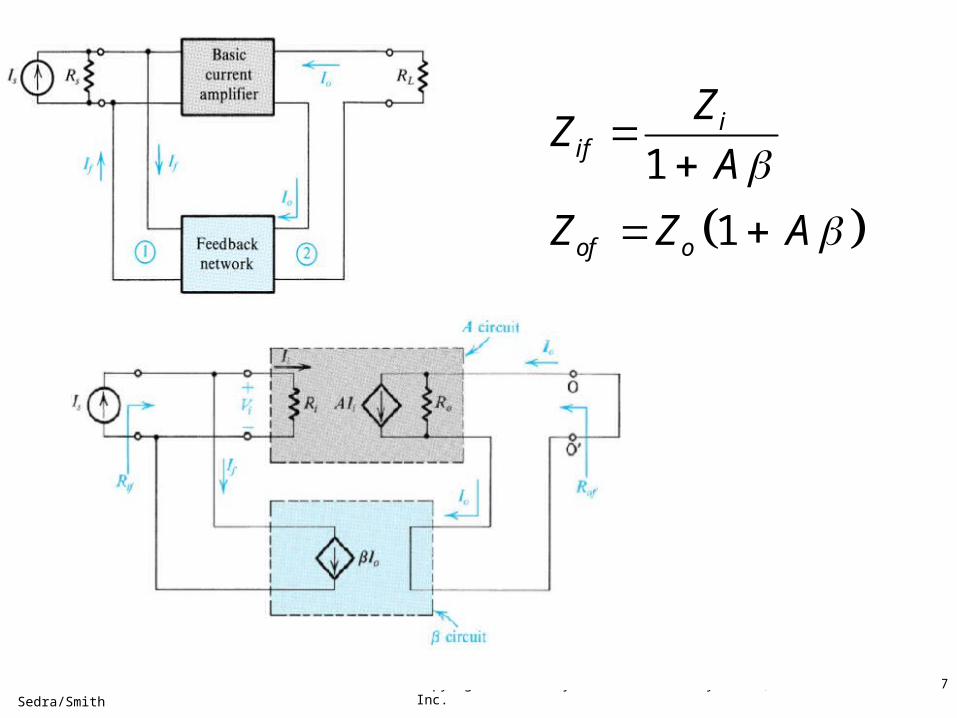
Microelectronic Circuits - Fifth Edition Sedra/Smith 17Copyright 2004 by Oxford University Press, Inc.
1
1
iif
of o
ZZ
A
Z Z A
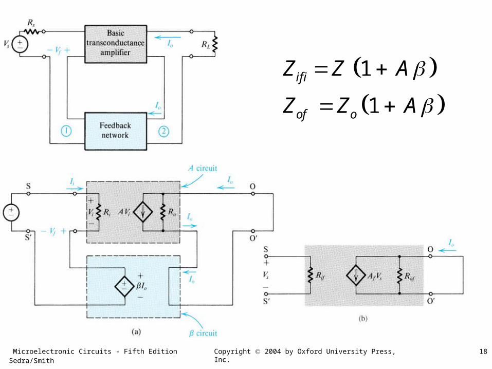
Microelectronic Circuits - Fifth Edition Sedra/Smith 18Copyright 2004 by Oxford University Press, Inc.
1
1
if i
of o
Z Z A
Z Z A
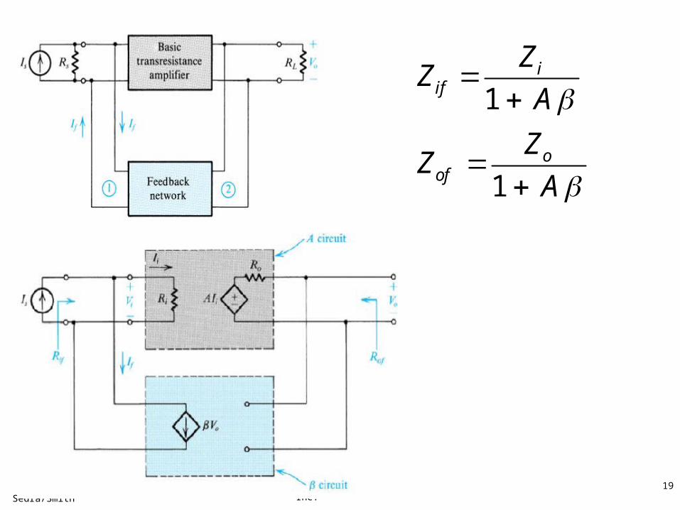
Microelectronic Circuits - Fifth Edition Sedra/Smith 19Copyright 2004 by Oxford University Press, Inc.
1
1
iif
oof
ZZ
A
ZZ
A


![[ Sedra] Microelectronic Circuits(b Ok.org)](https://img.pdfslide.us/doc/110x75/617b73ef7012c349660bd625/-sedra-microelectronic-circuitsb-okorg.jpg)