Embed Size (px)
Citation preview
1
Fan & Systems
Chris Carr PEH. Clay Moore & Associates
Rod FurnissHowden North America
Key Account Manager - Nuclear
2
• Pressure & Flow Definitions and Measurement• Development of Fan Curves• Performance of Various Blade Shapes• Fan Controls• System Effects
Aerodynamics3
3
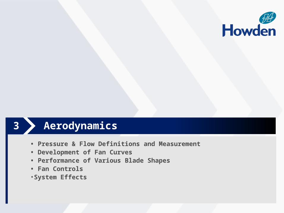
HNA Profile
4
Aerodynamics
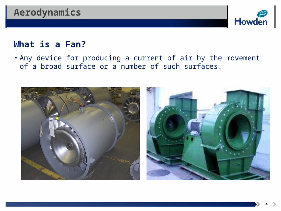
What is a Fan?
• Any device for producing a current of air by the movement of a broad surface or a number of such surfaces.
5
AerodynamicsPressure & Flow Definitions and Measurement
Fan Flow Rate
• Often called inlet volume
• Measured at the fan inlet, by convention
• Measured in cubic feet per minute (cfm)
• May be converted to scfm (standard cubic feet per minute), or mass flow (lb/hr)
• Fan manufacturers commonly use acfm (actual cubic feet per minute)
6
AerodynamicsPressure & Flow Definitions and Measurement
Pressure
• Force per Unit Area
• Commonly measured in psi or inwg
Absolute Pressure
• Pressure when the datum is absolute zero• iiAlways positive
Barometric Pressure
• Absolute pressure exerted by the atmosphere• Always positive
Gauge Pressure
• Pressure when the datum is barometric pressure• May be positive or negative
7
AerodynamicsPressure & Flow Definitions and Measurement
Static Pressure
• Pressure due to degree of compression and density only• May be positive or negative
Velocity Pressure
• Pressure due to rate of motion and density only• Always positive
Total Pressure
• Algebraic sum of static and velocity pressures at a point• May be positive or negative
8
AerodynamicsPressure & Flow Definitions and Measurement
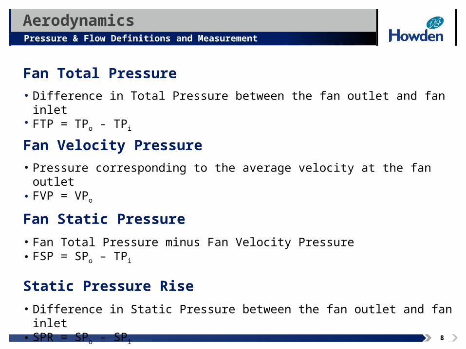
Fan Total Pressure
• Difference in Total Pressure between the fan outlet and fan inlet• FTP = TPo - TPi
Fan Velocity Pressure
• Pressure corresponding to the average velocity at the fan outlet• FVP = VPo
Fan Static Pressure
• Fan Total Pressure minus Fan Velocity Pressure• FSP = SPo – TPi
Static Pressure Rise
• Difference in Static Pressure between the fan outlet and fan inlet• SPR = SPo - SPi
9
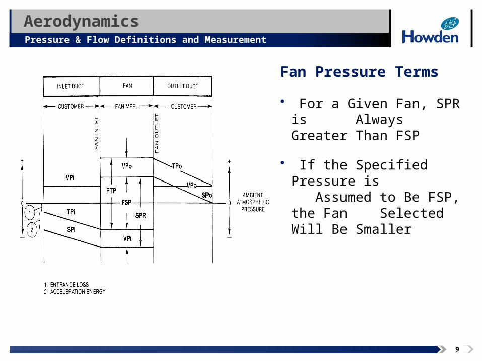
Fan Pressure Terms
• For a Given Fan, SPR is iiiAlways Greater Than FSP
• If the Specified Pressure is iiiAssumed to Be FSP, the Fan iiiSelected Will Be Smaller
AerodynamicsPressure & Flow Definitions and Measurement
Image area
10
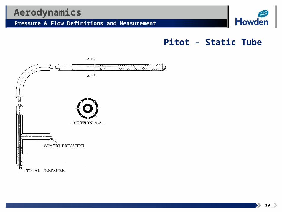
Pitot – Static Tube
AerodynamicsPressure & Flow Definitions and Measurement
Image area
11
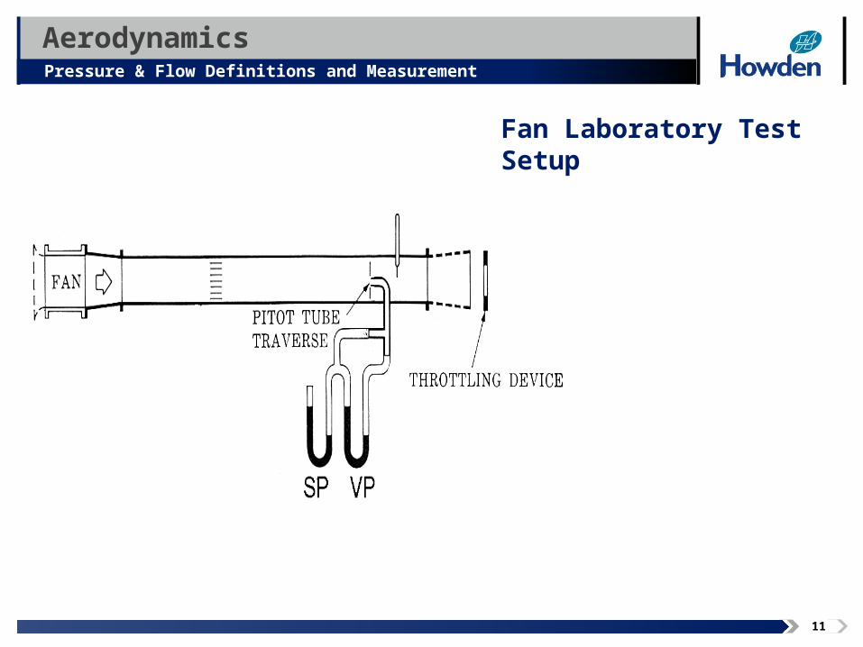
Fan Laboratory Test Setup
AerodynamicsPressure & Flow Definitions and Measurement
Image area
12
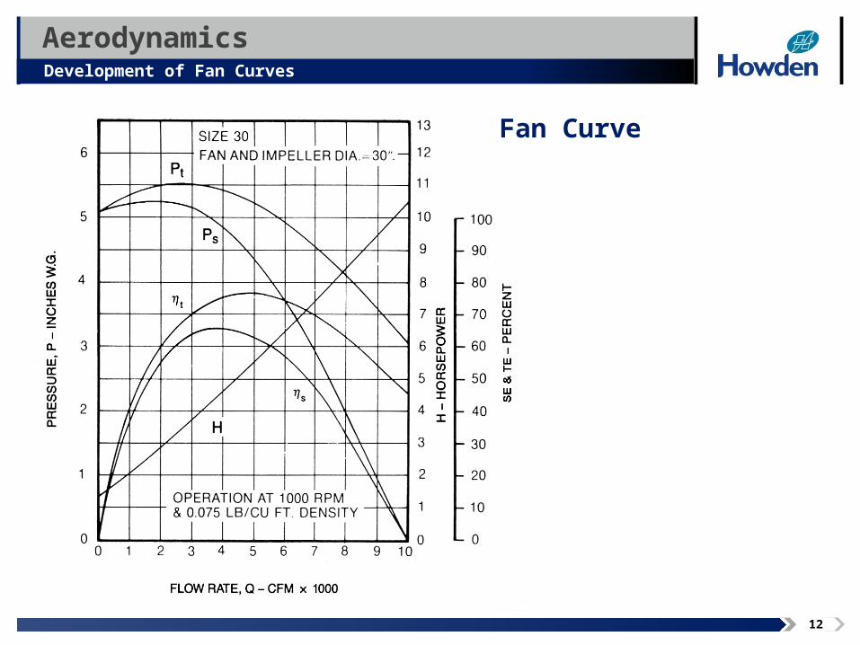
AerodynamicsDevelopment of Fan Curves
Image area
Fan Curve
13
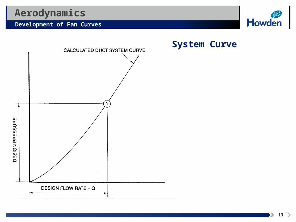
AerodynamicsDevelopment of Fan Curves
Image area
System Curve
14
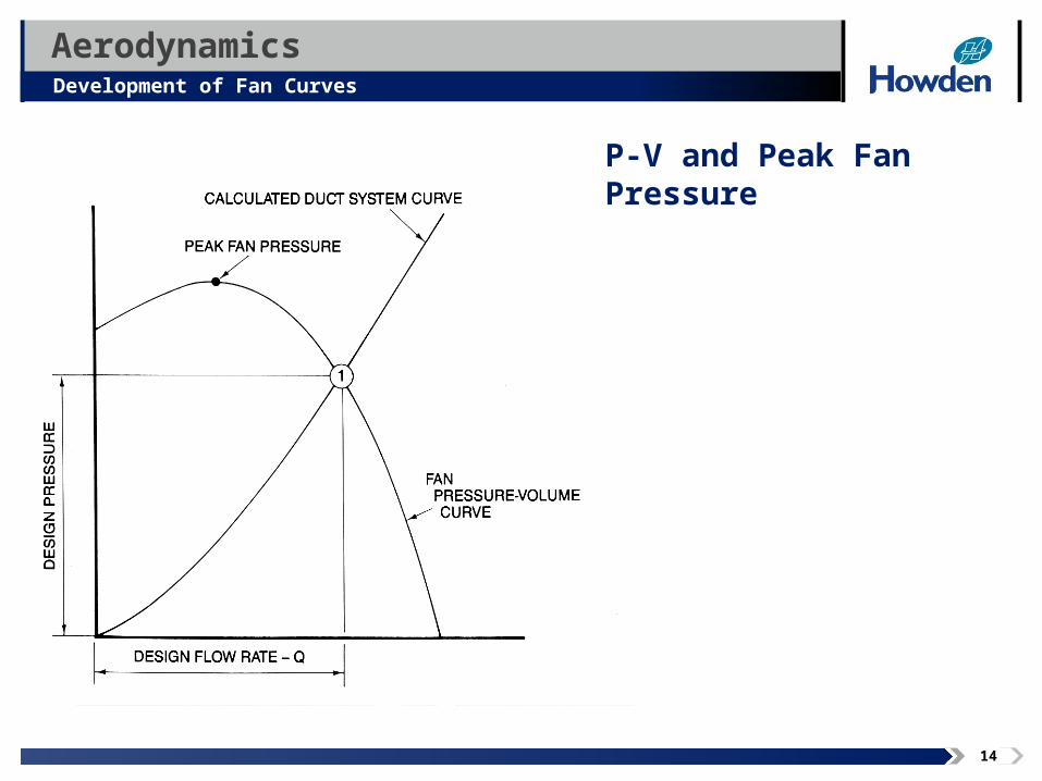
AerodynamicsDevelopment of Fan Curves
Image area
P-V and Peak Fan Pressure
15
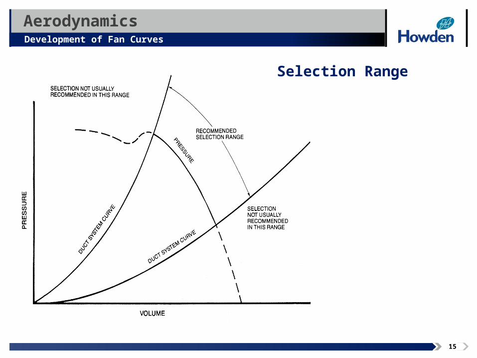
AerodynamicsDevelopment of Fan Curves
Image area
Selection Range
16
AerodynamicsPerformance of Various Blade Shapes
Common Blade Shapes
• Airfoil
• Backward Curved / Backward Inclined
• Radial / Radial Tip
• Forward Curved
• Axial
17
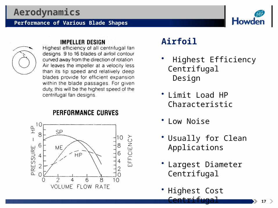
Airfoil
• Highest Efficiency Centrifugal DDesign
• Limit Load HP Characteristic
• Low Noise
• Usually for Clean Applications
• Largest Diameter Centrifugal
• Highest Cost Centrifugal
AerodynamicsPerformance of Various Blade Shapes
Image area
18
AerodynamicsPerformance of Various Blade Shapes
Image area
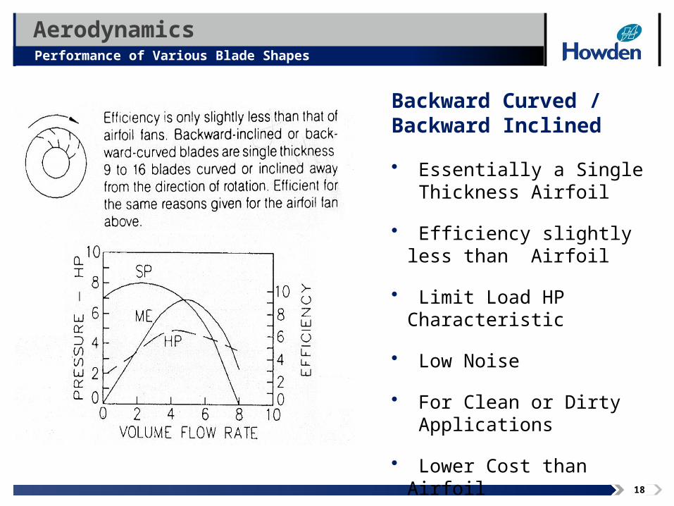
Backward Curved / Backward Inclined
• Essentially a Single TThickness Airfoil
• Efficiency slightly less than AAirfoil
• Limit Load HP Characteristic
• Low Noise
• For Clean or Dirty AApplications
• Lower Cost than Airfoil
19
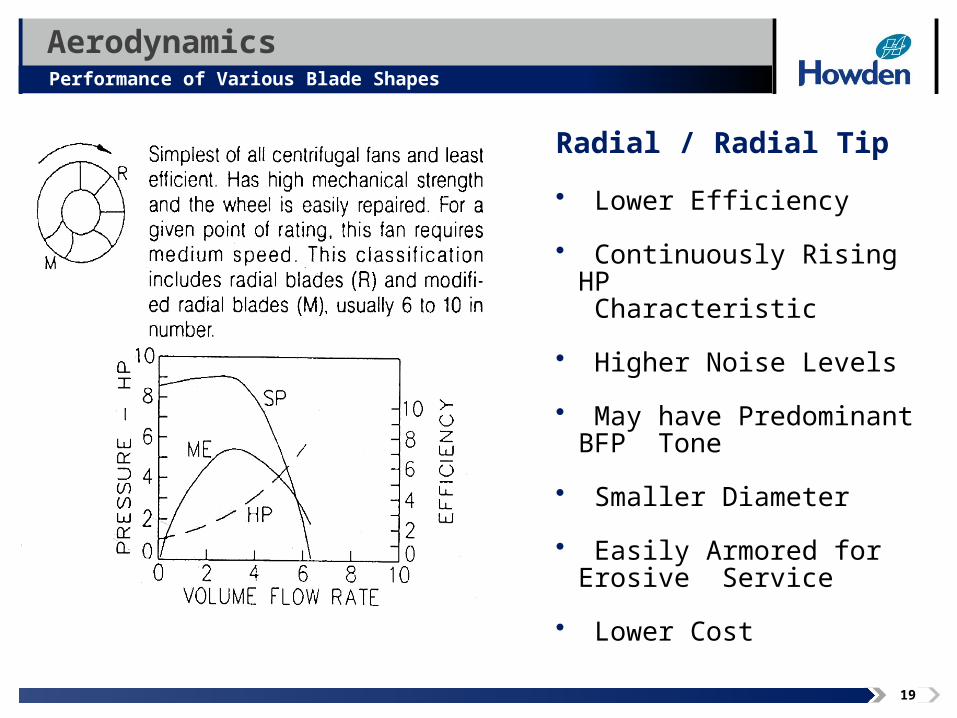
Radial / Radial Tip
• Lower Efficiency
• Continuously Rising HP .. CCharacteristic
• Higher Noise Levels
• May have Predominant BFP TTone
• Smaller Diameter
• Easily Armored for Erosive SService
• Lower Cost
AerodynamicsPerformance of Various Blade Shapes
Image area
20
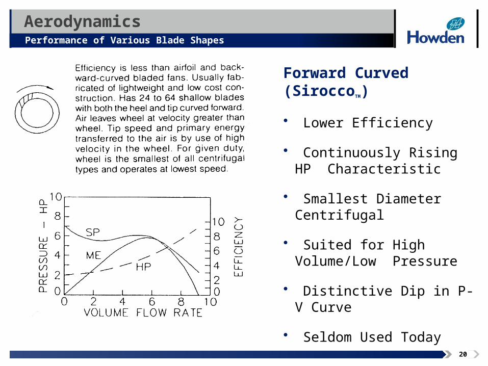
Forward Curved (SiroccoTM)
• Lower Efficiency
• Continuously Rising HP CCharacteristic
• Smallest Diameter Centrifugal
• Suited for High Volume/Low PPressure
• Distinctive Dip in P-V Curve
• Seldom Used Today
AerodynamicsPerformance of Various Blade Shapes
Image area
21
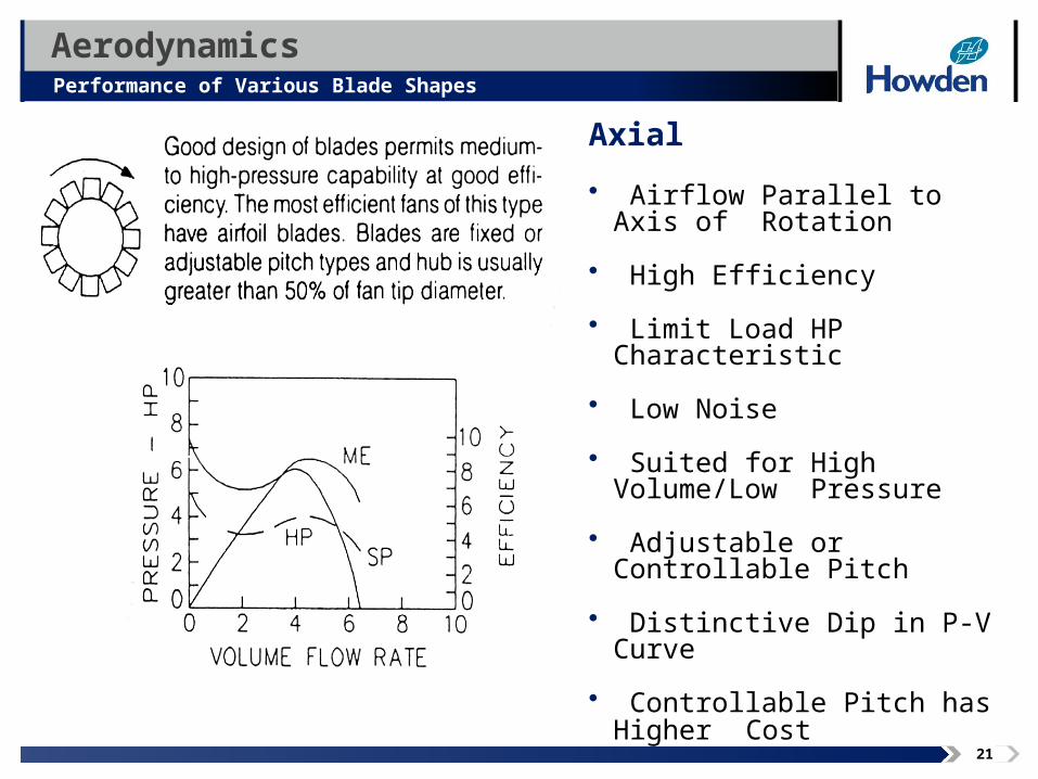
Axial
• Airflow Parallel to Axis of RRotation
• High Efficiency
• Limit Load HP Characteristic
• Low Noise
• Suited for High Volume/Low PPressure
• Adjustable or Controllable Pitch
• Distinctive Dip in P-V Curve
• Controllable Pitch has Higher CCost
AerodynamicsPerformance of Various Blade Shapes
Image area
22
AerodynamicsFan Controls
Fan Control
• Reasons for Providing Fan Control
• Methods of Control
• Efficiency Comparison
• Mechanical Arrangements
• Control Criteria
23
AerodynamicsFan Controls
Reasons for Providing Fan Control
• Uncertainty in System Calculations
• Safety Factor or Margin
• Expected Changes in the System with Time
• Normal Process Variations
• Provisions for Extraordinary Events
24
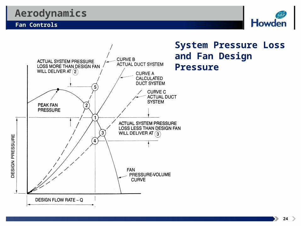
AerodynamicsFan Controls
Image area
System Pressure Loss and Fan Design Pressure
25
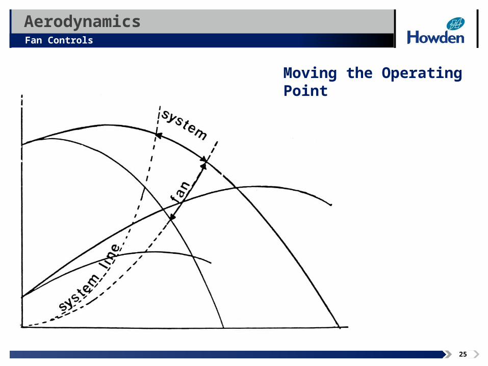
AerodynamicsFan Controls
Image area
Moving the Operating Point
26
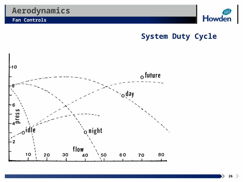
AerodynamicsFan Controls
Image area
System Duty Cycle
27
AerodynamicsFan Controls
Methods of Control
• None
• Outlet / System Damper
• Inlet Box Dampers
• Variable Inlet Vanes (VIV)
• Variable Speed
• Blade Pitch Control
• Combinations of the Above
28
AerodynamicsFan Controls
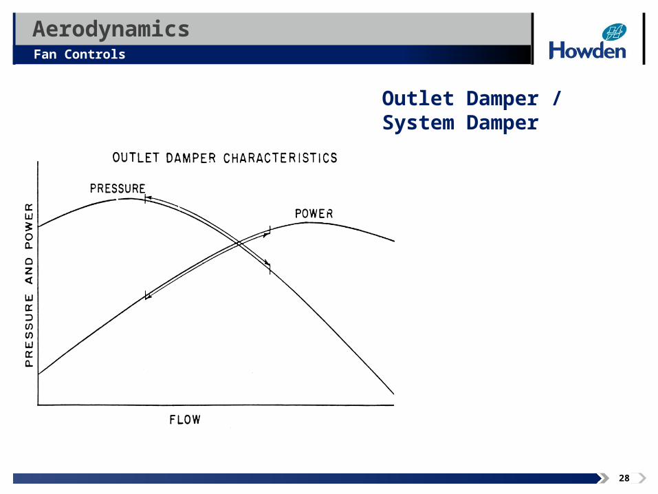
Image area
Outlet Damper / System Damper
29
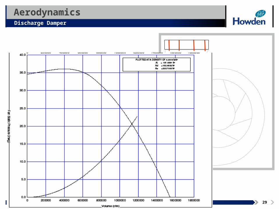
AerodynamicsDischarge Damper
30
AerodynamicsFan Controls
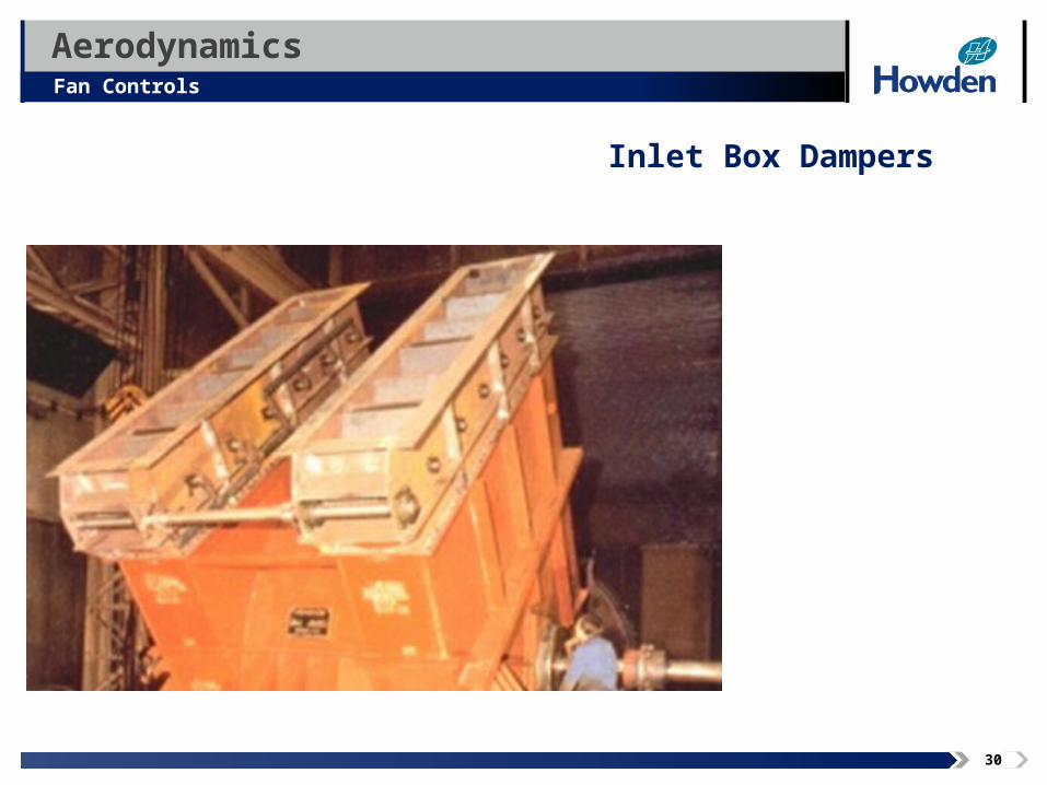
Image area
Inlet Box Dampers
31
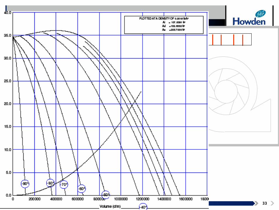
AerodynamicsFan Controls
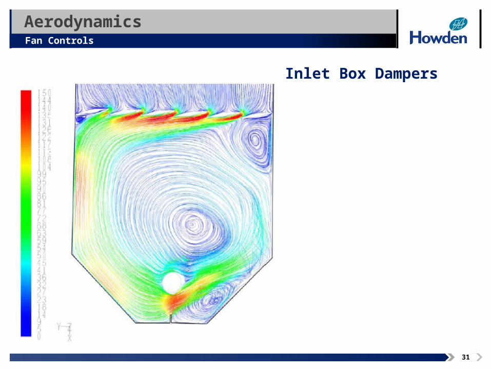
Image area
Inlet Box Dampers
32
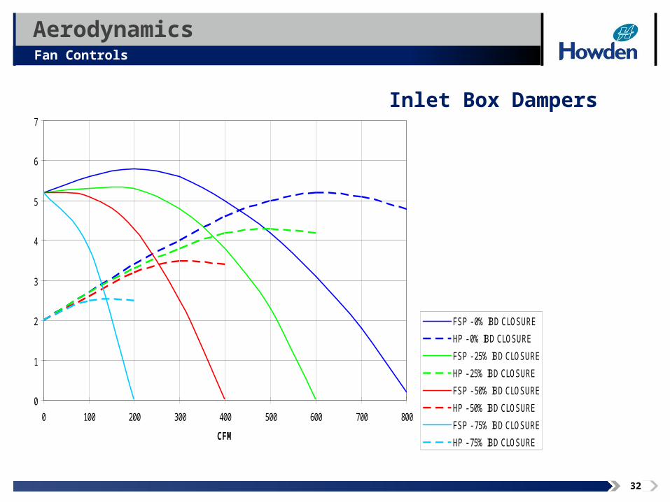
AerodynamicsFan Controls
Image area
Inlet Box Dampers
0
1
2
3
4
5
6
7
0 100 200 300 400 500 600 700 800
CFM
FSP - 0% IBD CLOSURE
HP - 0% IBD CLOSURE
FSP - 25% IBD CLOSURE
HP - 25% IBD CLOSURE
FSP - 50% IBD CLOSURE
HP - 50% IBD CLOSURE
FSP - 75% IBD CLOSURE
HP - 75% IBD CLOSURE
33

34
IBD
Discharge
35
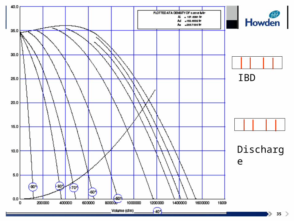
IBD
Discharge
36
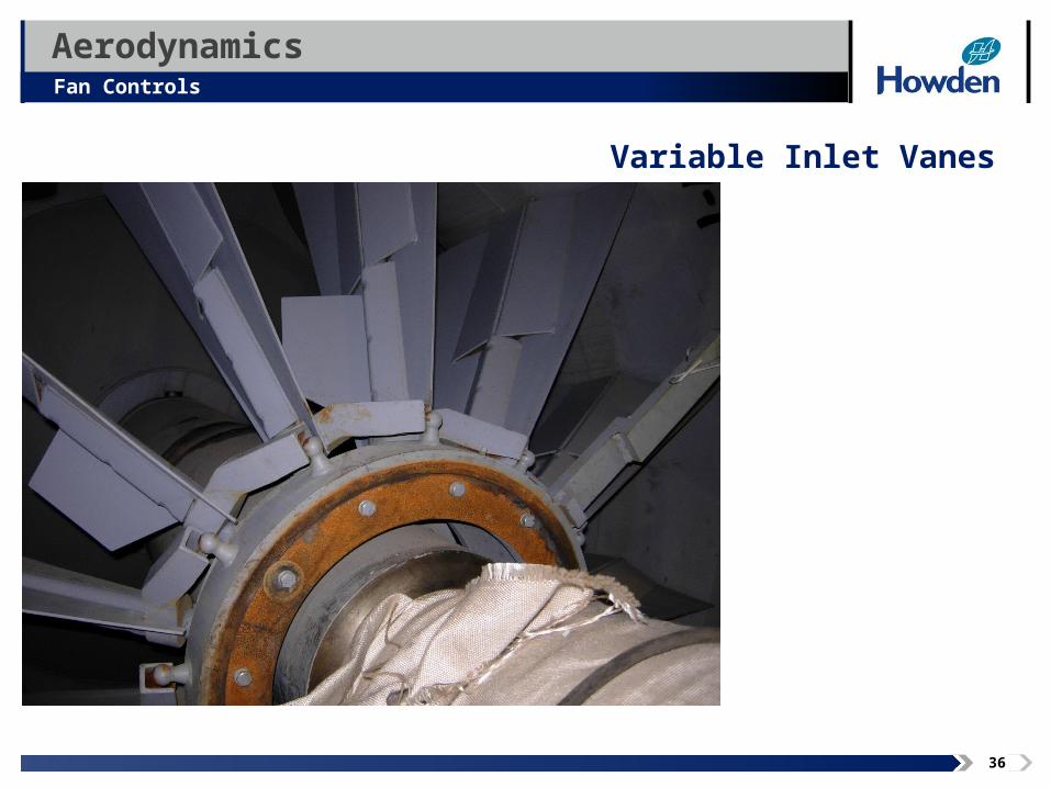
AerodynamicsFan Controls
Image area
Variable Inlet Vanes
37
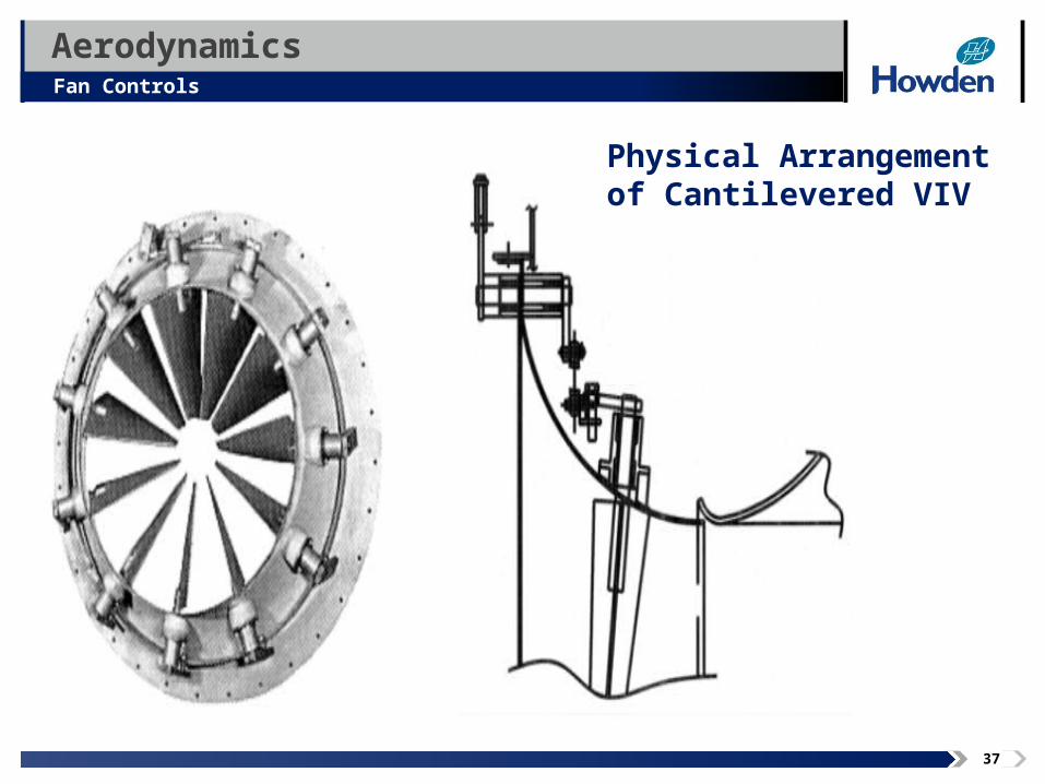
AerodynamicsFan Controls
Image area
Physical Arrangement of Cantilevered VIV
38
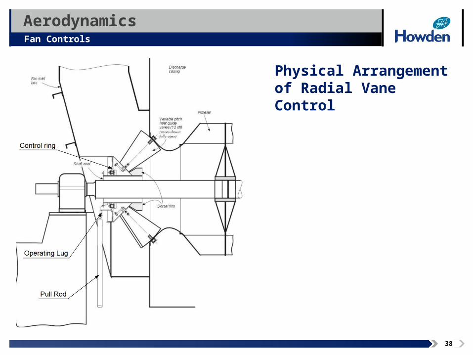
AerodynamicsFan Controls
Image area
Physical Arrangement of Radial Vane Control
39
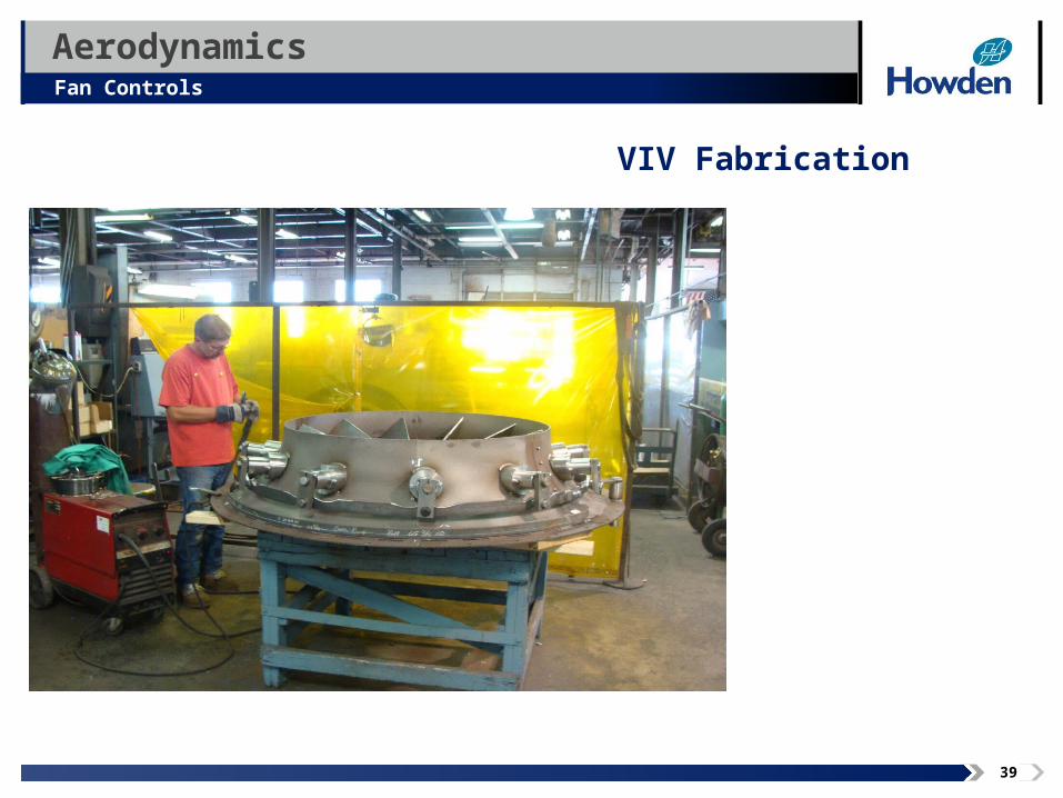
AerodynamicsFan Controls
Image area
VIV Fabrication
40
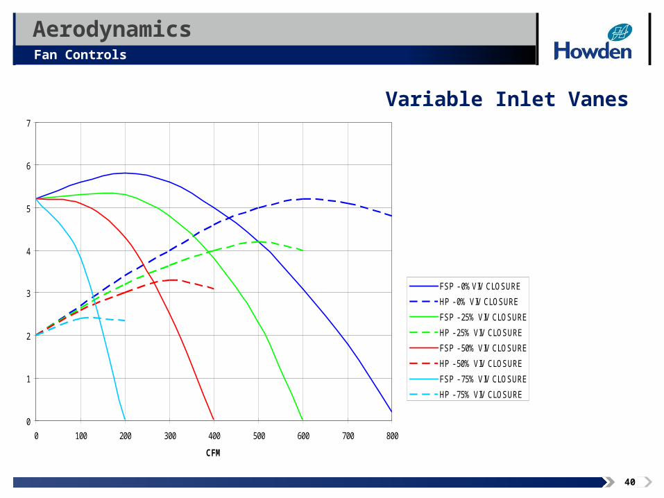
AerodynamicsFan Controls
Image area
Variable Inlet Vanes
0
1
2
3
4
5
6
7
0 100 200 300 400 500 600 700 800
CFM
FSP - 0%VIV CLOSURE
HP - 0% VIV CLOSURE
FSP - 25% VIV CLOSURE
HP - 25% VIV CLOSURE
FSP - 50% VIV CLOSURE
HP - 50% VIV CLOSURE
FSP - 75% VIV CLOSURE
HP - 75% VIV CLOSURE
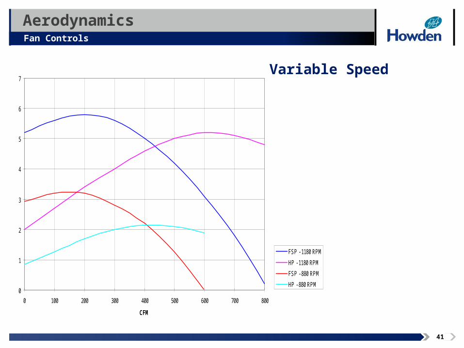
41
AerodynamicsFan Controls
Image area
Variable Speed
0
1
2
3
4
5
6
7
0 100 200 300 400 500 600 700 800
CFM
FSP - 1180 RPM
HP - 1180 RPM
FSP - 880 RPM
HP - 880 RPM

42
Rotating
Stall
AerodynamicsFan Controls
Variable Speed- VFD
and Gỳrol Fluid Drive
43
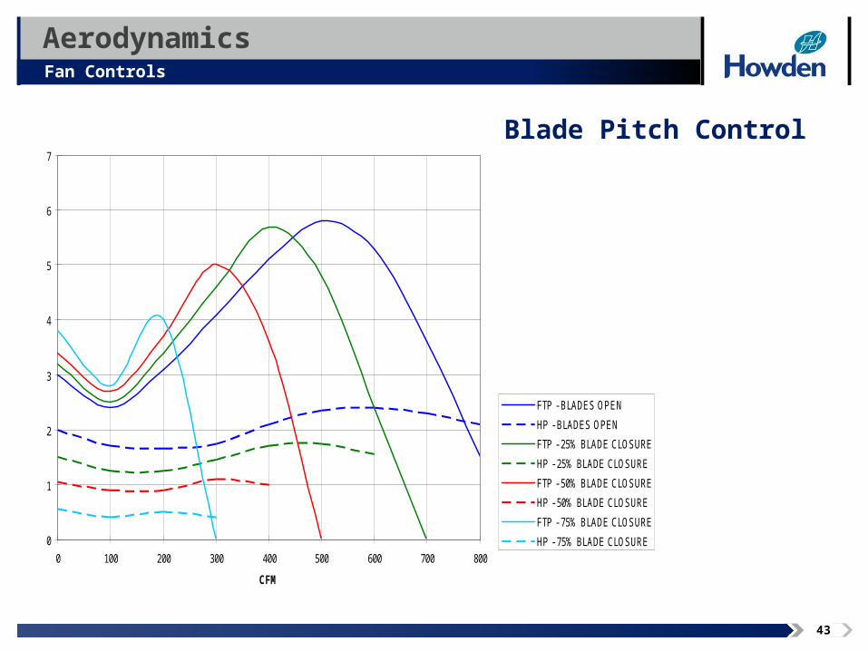
AerodynamicsFan Controls
Image area
Blade Pitch Control
0
1
2
3
4
5
6
7
0 100 200 300 400 500 600 700 800
CFM
FTP - BLADES OPEN
HP - BLADES OPEN
FTP - 25% BLADE CLOSURE
HP - 25% BLADE CLOSURE
FTP - 50% BLADE CLOSURE
HP - 50% BLADE CLOSURE
FTP - 75% BLADE CLOSURE
HP - 75% BLADE CLOSURE
44
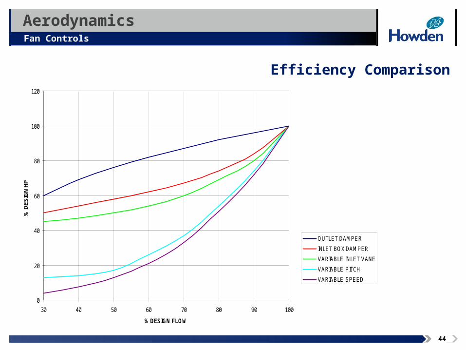
AerodynamicsFan Controls
Image area
Efficiency Comparison
0
20
40
60
80
100
120
30 40 50 60 70 80 90 100
% DESIGN FLOW
% D
ES
IGN
HP
OUTLET DAMPER
INLET BOX DAMPER
VARIABLE INLET VANE
VARIABLE PITCH
VARIABLE SPEED
45
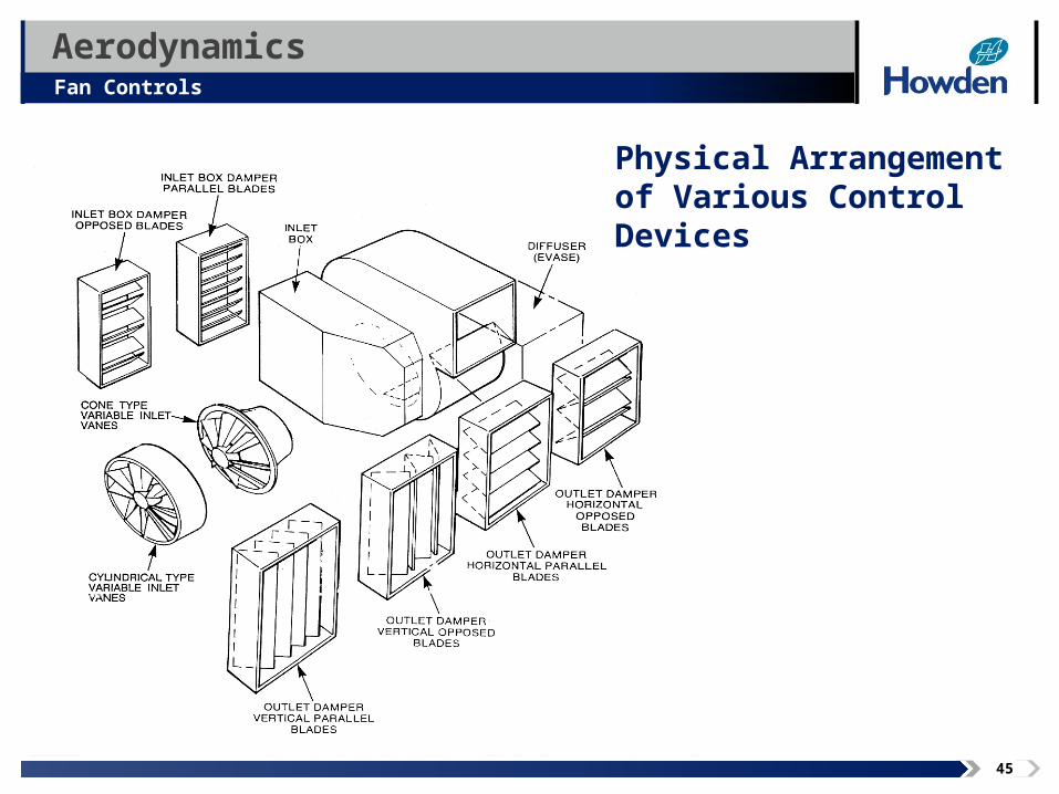
AerodynamicsFan Controls
Image area
Physical Arrangement of Various Control Devices
46
AerodynamicsFan Controls
Image area
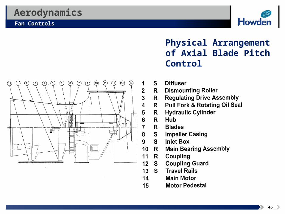
Physical Arrangement of Axial Blade Pitch Control
47
AerodynamicsFan Controls
Control Criteria
• Turndown / Leakage
• Sensitivity to Change / Stability / Transients
• Accuracy Required
• Repeatability
• Expected Efficiency
• Acoustic Considerations
• Structural Considerations
48
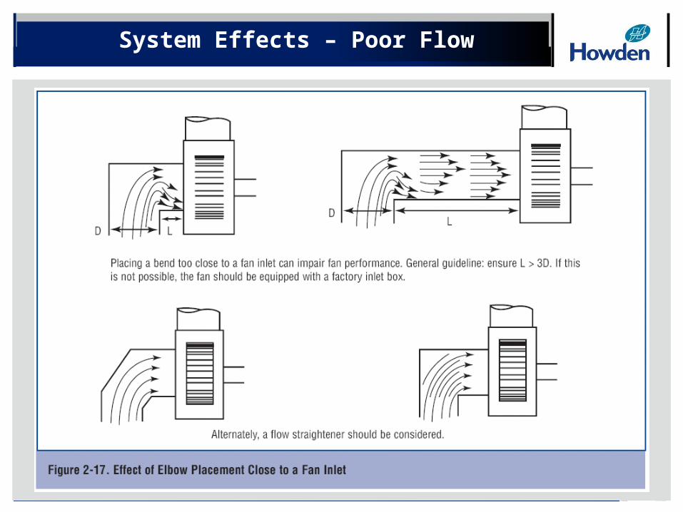
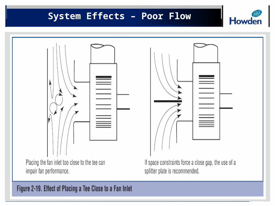
System Effects – Poor Flow
49
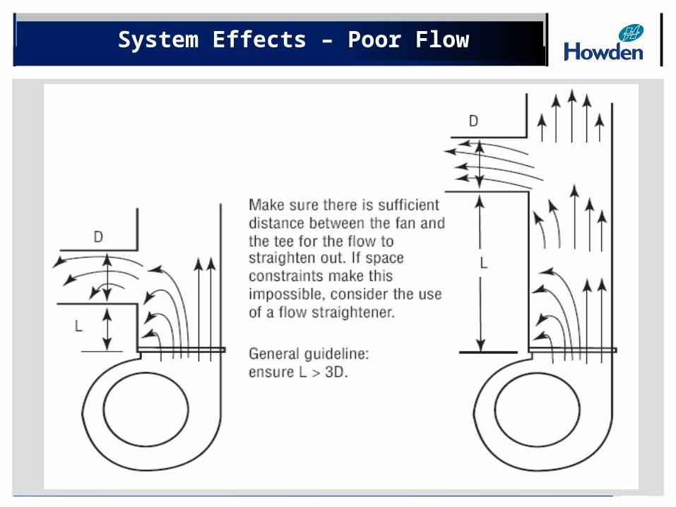
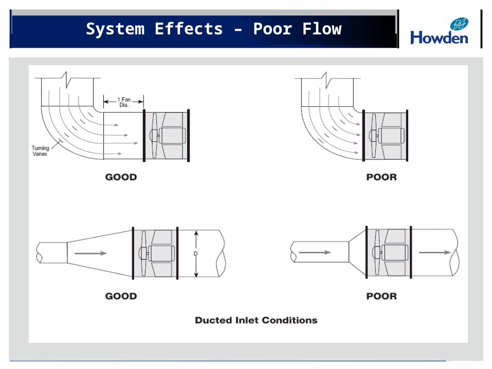
System Effects – Poor Flow
50
System Effects – Poor Flow
51
System Effects – Poor Flow

52
Fan & Systems
Chris Carr PEH. Clay Moore & Associates
Rod FurnissHowden North America
Key Account Manager - Nuclear