Embed Size (px)
Citation preview
01-30000-00
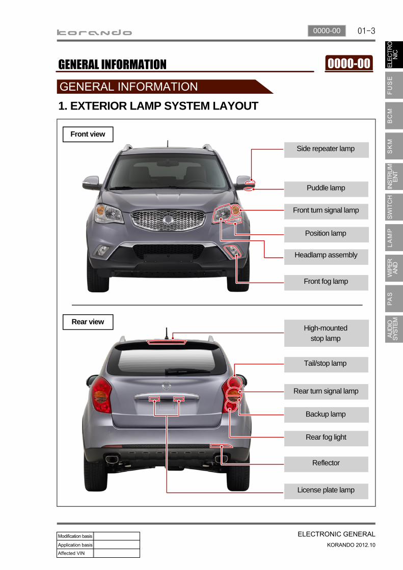
Front turn signal lamp
Side repeater lamp
Puddle lamp
1. EXTERIOR LAMP SYSTEM LAYOUT
Front fog lamp
Position lamp
Headlamp assembly
Rear turn signal lamp
High-mounted stop lamp
Tail/stop lamp
Reflector
Backup lamp
Rear fog light
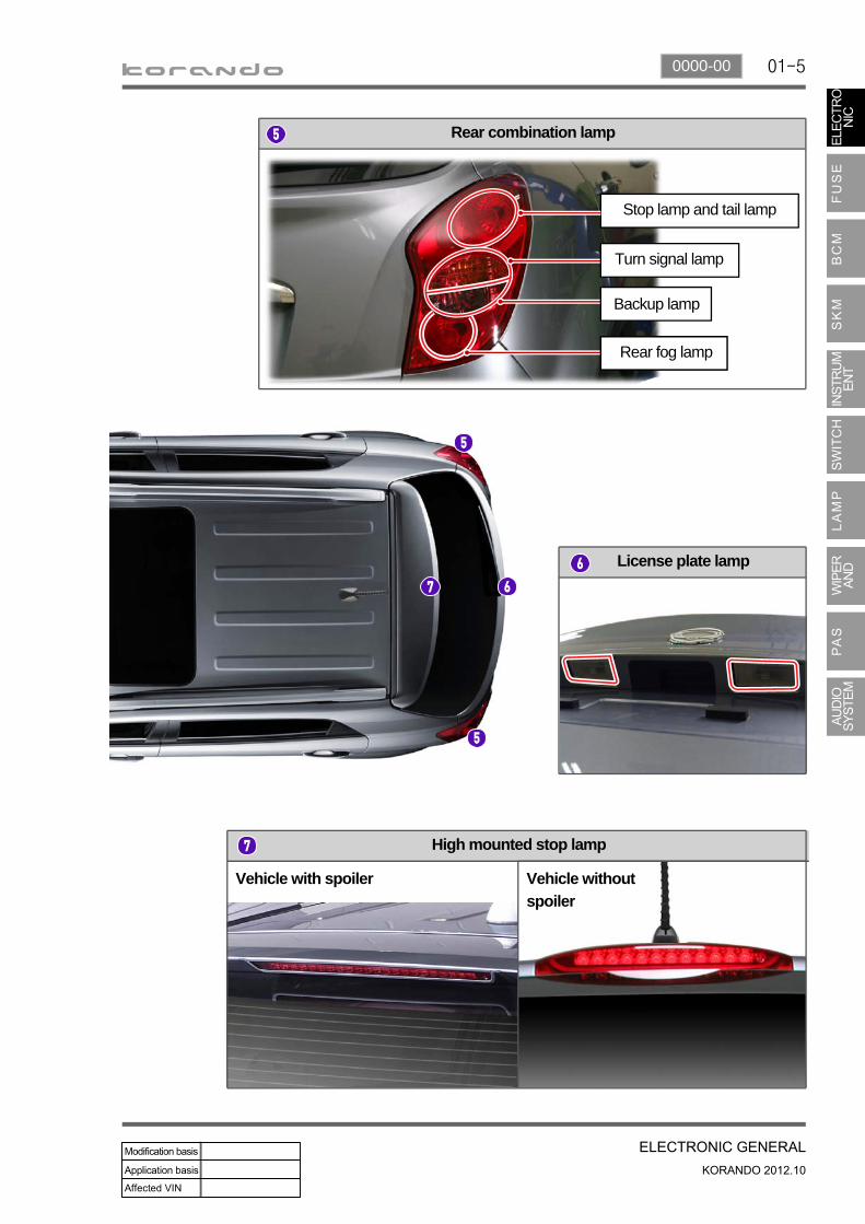
License plate lamp
Front view
Rear view
01-4
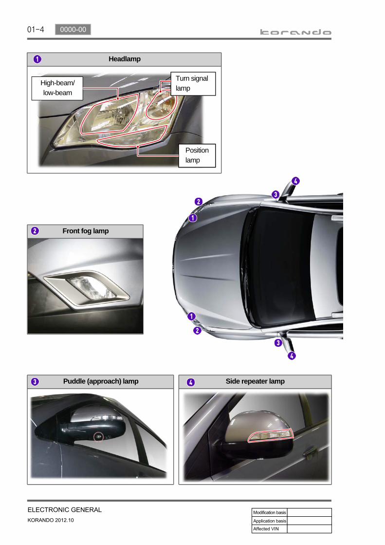
Puddle (approach) lamp
Front fog lamp
Headlamp
Side repeater lamp
High-beam/low-beam
Turn signal lamp
Position lamp
01-50000-00
High mounted stop lamp
Rear combination lamp
Vehicle without
spoiler
Vehicle with spoiler
License plate lamp
Stop lamp and tail lamp
Rear fog lamp
Turn signal lamp
Backup lamp
01-6
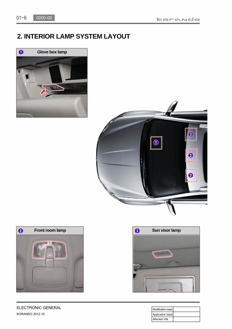
Sun visor lamp
Glove box lamp
Front room lamp
2. INTERIOR LAMP SYSTEM LAYOUT
01-70000-00
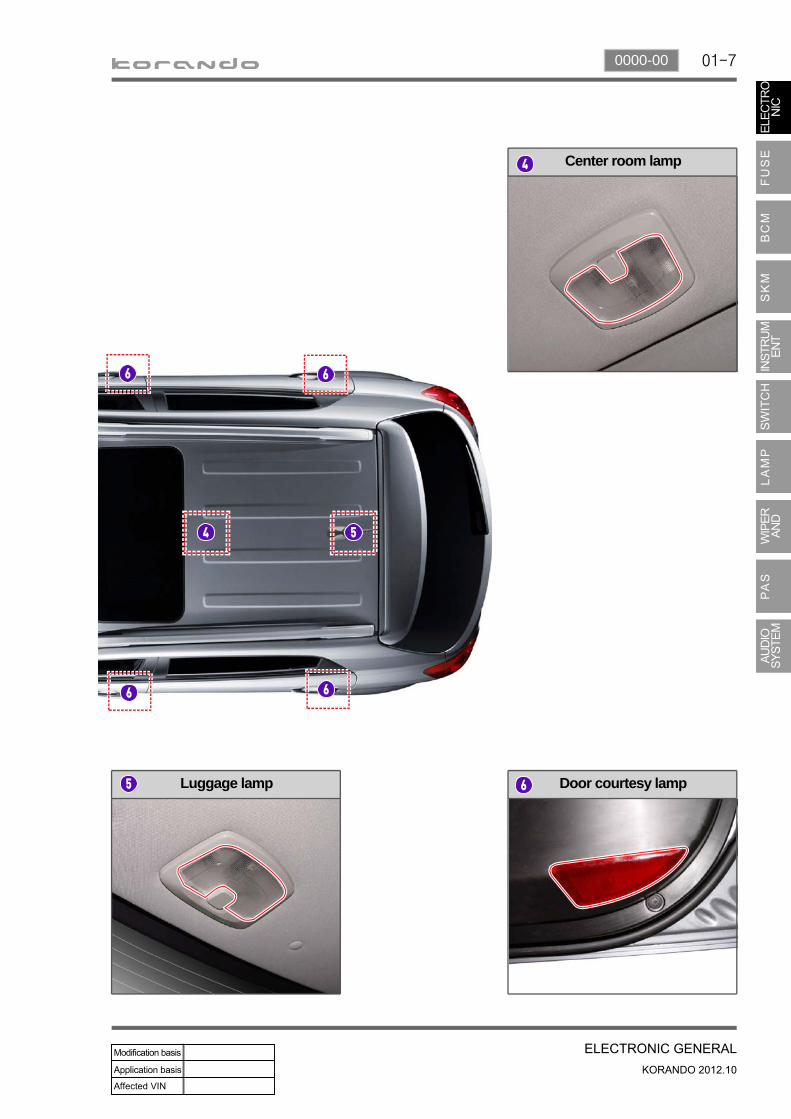
Center room lamp
Luggage lamp Door courtesy lamp
01-8
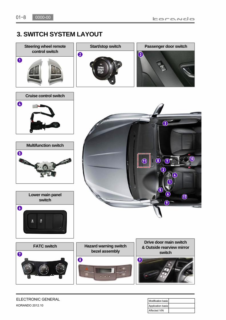
Steering wheel remote control switch
Passenger door switch
Lower main panel switch
Start/stop switch
Cruise control switch
Hazard warning switch bezel assembly
Multifunction switch
FATC switchDrive door main switch
& Outside rearview mirror switch
3. SWITCH SYSTEM LAYOUT
01-90000-00
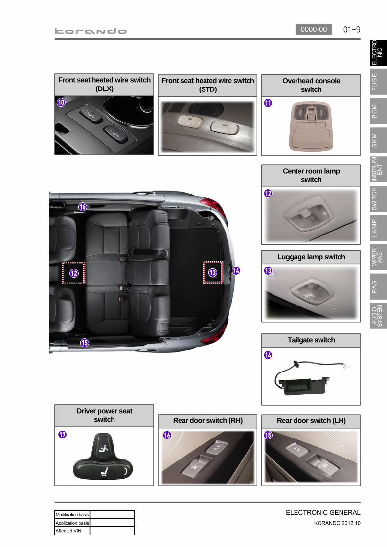
Center room lamp switch
Front seat heated wire switch (STD)
Rear door switch (RH)
Overhead console switch
Rear door switch (LH)
Tailgate switch
Front seat heated wire switch (DLX)
Luggage lamp switch
Driver power seat switch
01-10
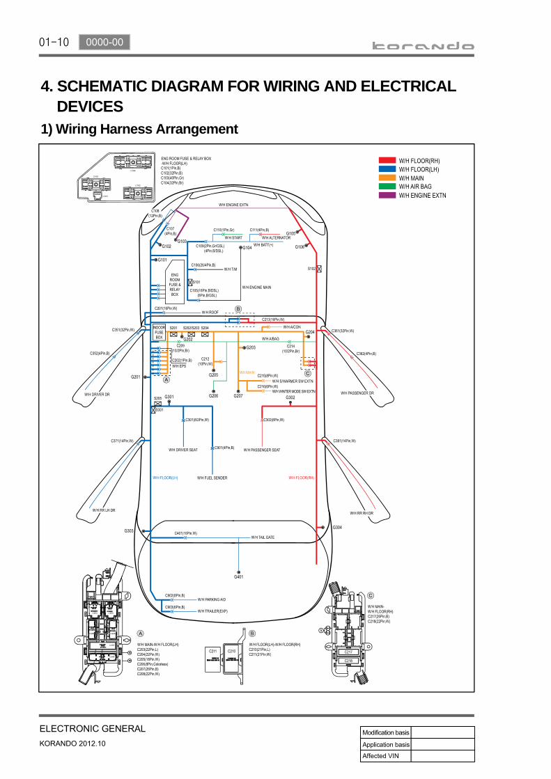
4. SCHEMATIC DIAGRAM FOR WIRING AND ELECTRICAL DEVICES1) Wiring Harness Arrangement
01-110000-00
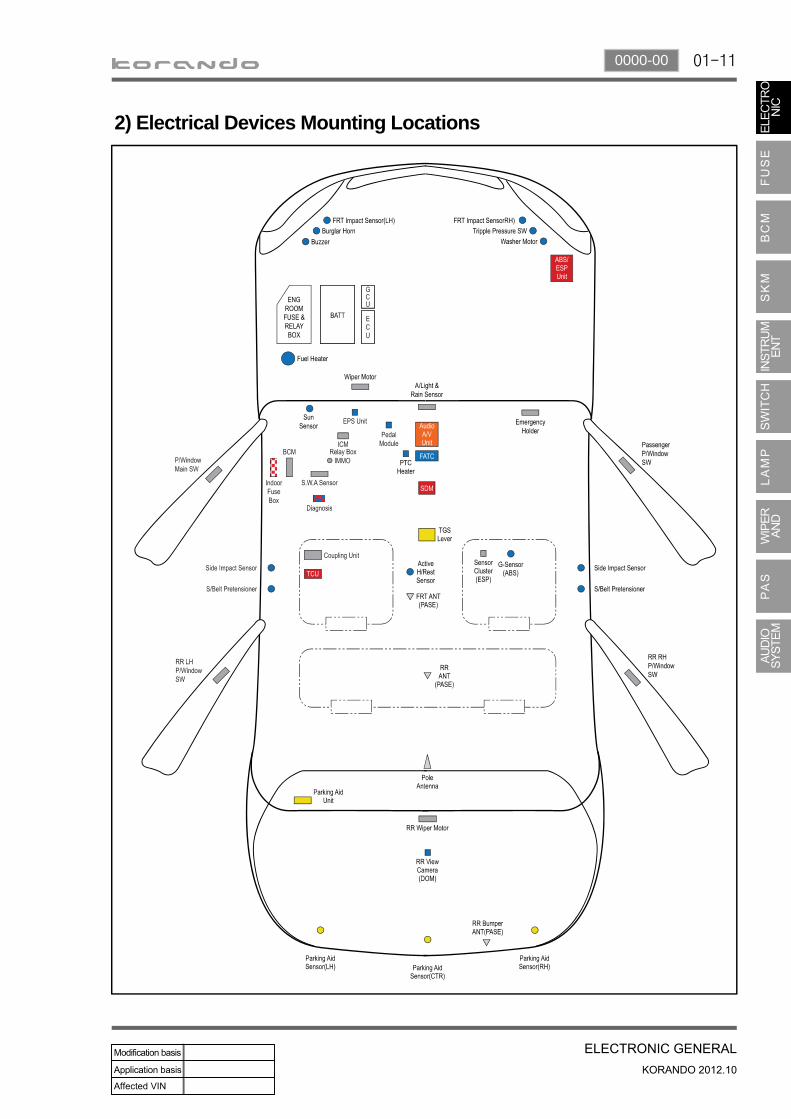
2) Electrical Devices Mounting Locations
01-12
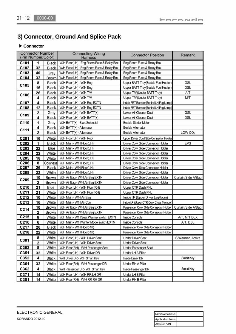
3) Connector, Ground And Splice Pack
Connector▶
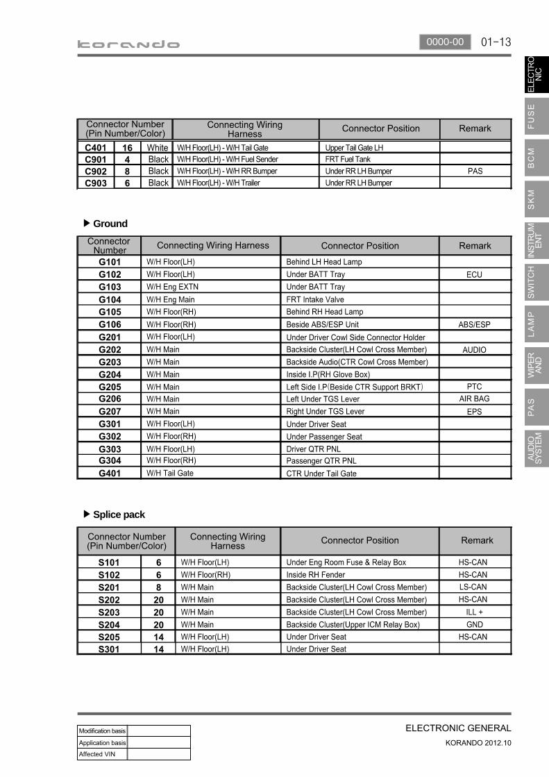
01-130000-00
Ground▶
Splice pack▶
01-14
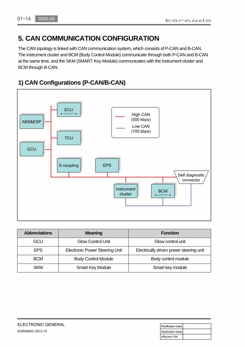
5. CAN COMMUNICATION CONFIGURATIONThe CAN topology is linked with CAN communication system, which consists of P-CAN and B-CAN. The instrument cluster and BCM (Body Control Module) communicate through both P-CAN and B-CAN at the same time, and the SKM (SMART Key Module) communicates with the instrument cluster and BCM through B-CAN.
1) CAN Configurations (P-CAN/B-CAN)
Abbreviations Meaning Function
GCU Glow Control Unit Glow control unit
EPS Electronic Power Steering Unit Electrically driven power steering unit
BCM Body Control Module Body control module
SKM Smart Key Module Smart key module
01-150000-00
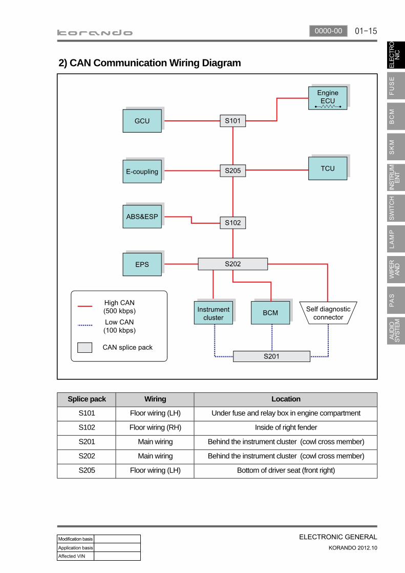
2) CAN Communication Wiring Diagram
Splice pack Wiring Location
S101 Floor wiring (LH) Under fuse and relay box in engine compartment
S102 Floor wiring (RH) Inside of right fender
S201 Main wiring Behind the instrument cluster (cowl cross member)
S202 Main wiring Behind the instrument cluster (cowl cross member)
S205 Floor wiring (LH) Bottom of driver seat (front right)


![2015Y LED EXTERIOR&INDUSTRIAL LUMINAIRE 2015Y · [ 2015Y FLIP-C ] LED Technology Ideal Replacement MH&HPS Street Lamp The Optimized Fusion of LED technology and the elegance appearance](https://img.pdfslide.us/doc/110x75/5e85fd6426b01c304e0d1e79/2015y-led-exteriorindustrial-luminaire-2015y-2015y-flip-c-led-technology.jpg)