Embed Size (px)
Citation preview
1 Exam Prep – Photovoltaic Systems, 3rd Edition 1
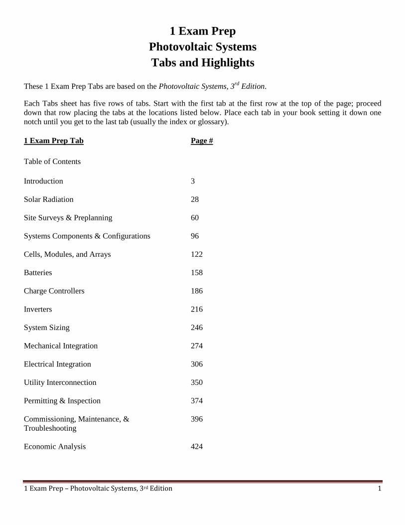
1 Exam Prep
Photovoltaic Systems
Tabs and Highlights
These 1 Exam Prep Tabs are based on the Photovoltaic Systems, 3rd
Edition.
Each Tabs sheet has five rows of tabs. Start with the first tab at the first row at the top of the page; proceed
down that row placing the tabs at the locations listed below. Place each tab in your book setting it down one
notch until you get to the last tab (usually the index or glossary).
1 Exam Prep Tab Page #
Table of Contents
Introduction 3
Solar Radiation 28
Site Surveys & Preplanning 60
Systems Components & Configurations 96
Cells, Modules, and Arrays 122
Batteries 158
Charge Controllers 186
Inverters 216
System Sizing 246
Mechanical Integration 274
Electrical Integration 306
Utility Interconnection 350
Permitting & Inspection 374
Commissioning, Maintenance, & 396
Troubleshooting
Economic Analysis 424

1 Exam Prep – Photovoltaic Systems, 3rd Edition 2
1 Exam Prep Tab Page #
Appendix 457
Glossary 483
Index 493
This concludes the tabs for this book. Please continue with the highlights below.
Page # Highlight
4 Photovoltaics: Photovoltaics is a solar energy technology that uses the unique properties
of certain semi-conductors to directly convert solar radiation in electricity.
A photovoltaic (PV) system is an electrical system consisting of a PV module array and
other electrical components needed to convert solar energy into electricity usable by
loads.
Advantages: the PV system may save the consumer a great deal of money
Photovoltaics is an environmentally friendly technology that produces energy with no
noise or pollution.
Since there are no moving parts, PV systems are extremely reliable and last a long time
with minimal maintenance.
PV system reduces the consumer’s vulnerability to utility outages, and a stand-alone
system eliminates it.
Disadvantages: Currently, the most significant issue is the high initial cost of a PV
system.
5 Typical Utility-Connected PV System
6 Distributed generation is a system in which many … A distributed generation system
may serve as the only source of power for the consumer (a stand-alone system), or as
backup or supplemental power for a utility connection.
11 PV Applications: Today, PV systems can be used in almost any application where
electricity is needed and can support DC loads, AC loads, or both.
Portable Applications: Portable PV systems power mobile loads such as vehicles,
temporary sign and lighting, and handheld devices.
12 Remote Applications. Remote PV systems power loads that are permanently fixed but
too distant to be connected to the utility power grid.

1 Exam Prep – Photovoltaic Systems, 3rd Edition 3
Page # Highlight
12 Lighting. The availability of low-power DC lamps makes PV energy ideal for remote
lighting applications.
13 Utility-Interactive Applications: Systems that are connected to the utility grid and use
PV energy as a supplemental source of power offer the greatest flexibility.
A PV system may or may not save in money in the short-term when competing against
relatively inexpensive utility power.
14 PV systems can be used to provide supplemental power to any utility-connected building
… and institutions.
Utility-Scale Applications: The only moving parts of a PV system are in the tracking
system, if one is used.
Unfortunately, PV electricity still costs considerably more in the United States than
electricity generated by conventional plants.
15 Figure 1-14 The PV industry is composed of several levels of businesses and
organizations.
Manufacturers: A balance-of-system (BOS) component is an electrical or structural
component, aside from a major component, that is required to complete a PV system.
BOS systems include the conductors, … array, inverter and battery system.
Integrators: An integrator is a business that designs, builds, and installs complete PV
systems for particular applications by matching components from various manufactures.
16 Silicon is the primary raw material for producing PV cells.
All PV system installers should meet the following criteria: (14 bullets).
17 Figure 1-15: Quality PV installation relies on the quality of the selected components,
system design, and installation practices.
21 Collectors: A solar energy collector is a device designed to absorb solar radiation and
convert it to another form.
Flat-plate collector: A flat-plate collector is a solar energy collector that absorbs solar
energy on a flat surface without concentrating it, and can utilize solar radiation … Nearly
all commercial and residential solar energy installations use flat-plate collectors.
22 Concentrating collectors: A concentrating collector is a solar energy collector that …
through reflective surfaces or lenses.
23 Solar Thermal Energy: Solar thermal energy systems convert solar radiation into heat
energy.
Solar Thermal Heating: Solar thermal heating systems can be classified as passive or
active. In passive systems, …are used to circulate the fluid.

1 Exam Prep – Photovoltaic Systems, 3rd Edition 4
Page # Highlight
24 Solar Thermal Cooling: The heat energy is used to compress a gas … cools a set of
coils.
Solar Thermal Electricity: Concentrating solar power (CSP) is a technology that uses
mirrors and/or lenses to reflect … large area onto a small area.
30 The Sun: An astronomical unit (AU) is the average distance between Earth and the sun
(93 million mi).
Solar Radiation
Solar Irradiance (Solar Power): Solar irradiance is the power of solar radiation per unit
area … expressed in units of watts per square meter or kilowatts per square meter.
31 Solar irradiance is used as a reference input condition … utilization equipment such as
PV modules.
Figure 2-3. Solar irradiance is solar power per unit area.
Figure 2-4: The inverse square law states that irradiance is reduced in proportion to the
inverse square of the distance from the source.
32 Solar Irradiation (Solar Energy): Solar irradiation is the total amount of solar energy
accumulated on an area over time.
Solar irradiation is commonly expressed in units of watts-hours per square meter or
kilowatts per square meter. Solar irradiation quantifies … and is the principal data needed
for sizing and estimating the performance of PV systems.
Solar irradiation can be calculated from average solar irradiance by applying the
following formula: [formula].
Figure 2-5. Solar irradiation equals the total solar irradiance received over time.
34 Figure 2-6. The electromagnetic spectrum is the range of all types of electromagnetic
radiation, which will vary with wave length.
Direct Radiation: Direct radiation is solar radiation directly from the sun that reaches
Earth’s surface without scattering.
Diffuse Radiation: Diffuse radiation is solar radiation that is scattered by the atmosphere
and clouds.
Albedo Radiation: Albedo radiation is solar radiation that is reflected from the Earth’s
surface back up through the atmosphere.
35 Figure 2-8. Solar radiation in the earth’s atmosphere includes direct, diffuse, and albedo
radiation.
Air Mass. Zenith is a point in the sky directly overhead a particular location. The zenith
angle is the angle between the sun and the zenith.
36 Figure 2-9. Air mass is a representation of the amount of atmosphere radiation that must
pass through to reach Earth’s surface.
37 Terrestrial Solar Radiation: Terrestrial solar radiation is solar radiation reaching the
surface of the Earth.

1 Exam Prep – Photovoltaic Systems, 3rd Edition 5
Page # Highlight
Peak sun hours is the number of hours required for a day’s total solar irradiation to
accumulate at peak sun condition.
The total irradiation for a day may be expressed in units of peak sun hours by dividing by
1000 W/ (peak sun irradiance).
Figure 2-10. Peak sun hours is an equivalent measure of total solar irradiation in a day.
Knowing the average number of peak sun hours on a given surface at a given location is
used to determine PV system performance.
40 Solar Radiation Measurement:
- Pyranometers. Solar irradiance is typically measured with a pyranometer. A
pyranometer is a sensor that measures the total global solar irradiance in a hemispherical
field of view.
41 - Pyrheliometers. Direct solar radiation is measured with a pyrheliometer. A
pyrheliometer is a sensor that measures only direct solar radiation in the field of view of
the solar disk.
They must be pointed directly at the sun.
42 Reference Cells. A reference cell is an encapsulated PV cell that outputs a known
amount of electrical current per unit of solar irradiance … the output current can be used
to indirectly measure irradiance.
Reference cells are highly accurate precision instruments … used to measure the output
of PV modules.
Sun-Earth Relationships: Earth axis is tilted at 23.5. The amount of solar radiation
received at a particular location on Earth’s surface is a direct result of Earth’s orbit and
tilt.
42-43 Earth’s Orbit: Perihelion is the point in Earth’s orbit that is closest to the sun … The
equatorial plane is the plane containing earth’s equator and extending outward into space.
Because Earth’s tilt, the angle between these planes is 2.5 and remains constant as Earth’s
makes its annual orbit around the sun.
43 Solar Declination: Solar declination is the angle between the equatorial plane and the
rays of the sun. The angle of solar declination changes continuously as Earth orbits
ranging from -23.5˚ to +23.5˚.
Figure 2-18. The ecliptic plane is formed by Earth’s elliptical orbit around the sun.
Figure 2-19. The equatorial plane is tilted 23.5˚ …this orientation produces a varying
solar declination.
44 Solstices: A solstice is the Earth’s orbital position when solar declination is at its
minimum or maximum. The summer solstice is at its maximum solar declination (+23.5˚)
and occurs around June 21.
The winter solstice is a at minimum solar declination (-23.5˚) and occurs around
December 21.

1 Exam Prep – Photovoltaic Systems, 3rd Edition 6
Page # Highlight
Figure 2-20. The summer solstice occurs when the Northern Hemisphere is tilted
towards the sun. The winter solstice occurs when the Northern Hemisphere is tilted away
from the sun.
Equinoxes. An equinox is the Earth’s orbital position when solar declination is zero …
The spring (vernal) equinox occurs around March 21 and the fall (autumnal) equinox
occurs around September 23.
Figure 2-21. The fall and spring equinoxes occur when the sun is directly in line with the
equator.
45 Solar Time: Solar time is a timescale based on the apparent motion of the sun.
Standard Time: Standard time is a timescale based on the apparent motion of the sun
crossing standard meridians. A standard meridian is a meridian located at a multiple of
15˚ east or west of zero longitude.
Figure 2-22. Standard time organizes regions into time zones.
46 The Equation of Time is the difference between solar time and standard time at a
standard meridian. This difference varies over the course of a year and can be as much as
+16 min or -14 min.
The longitude time correlation is calculated with the following equation: (equation).
Using both time correlations, local standard time can be converted to solar time, or vice
versa, with the following equations: (equation).
Figure 2-23. The Equation of Time adjusts for variations in the Earth’s orbit and rotation
that affect solar time.
47 Sun Path: An analemma is a diagram of solar declination against the Equation of Time.
Figure 2-24. An analemma shows how sun position, at the same time of day, changes
throughout the year.
Sun Position. The solar altitude angle is the vertical angle between the sun and the
horizon.
The solar azimuth angle is the horizontal angle between a reference direction and the sun.
Figure 2-26. The sun’s path across the sky at various times of the year.
49 The Solar Window: The solar window is the area of sky between sun paths at summer
solstice and winter solstice for a particular location. Knowing the solar window at a given
site is critical … to achieve optimal energy performance and to prevent shading from
trees and other obstructions.
Array Orientation: The array tilt angle is the vertical angle between horizontal and the
array surface. The array azimuth angle is the horizontal angle between the reference
direction and the direction an array surface faces.
Figure 2-27. The solar window is the area of the sky containing all possible locations of
the sun throughout the year for a particular location.

1 Exam Prep – Photovoltaic Systems, 3rd Edition 7
Page # Highlight
Figure 2-28. The orientation of an array surface is described using azimuth and tilt
angles.
50 Array Tilt Angle
51 Array Azimuth Angle
Sun Tracking: Sun tracking is continuously changing the array tilt angle, the array
azimuth angle, or both, so the array follows the position of the sun.
Single-axis tracking is a sun-tracking system that rotates one axis to approximately
follow the position of the sun.
Dual-axis tracking is a sun-tracking system that rotates two axes independently to follow
the position of the sun.
53 Solar Radiation Data Sets: Solar radiation data indicates how much solar energy trikes
a surface at a particular location on Earth during a period of time.
Figure 2-31. The NREL provides solar radiation data for various locations, times of the
year, and south-facing array orientations.
54 Solar Radiation for flat-Plate Collectors Facing South at Fixed Tilt: The section on
flat-plate collectors at fixed tilt is applicable to most installations.
56 Solar Radiation for Flat-Plate Collectors with Two-Axis Tracking: The section on
two-axis trackers represents solar irradiation on a surface that always faces the sun.
Two-axis tracking enables greater receiving of solar irradiation than either fixed or
single-axis tracking surfaces.
62 Customer Development: Sales persons, designers, and installers of PV systems must
identify customer needs, concerns, and expectations.
Solar Resource: The solar radiation resource should be researched before visiting the
site.
When reviewing the solar resource data, the installer should note the differences for
various array tilt angles … This is important when evaluating potential mounting
orientations for PV arrays.
64 Hazard Assessment and Safety Training
Personal Protective Equipment (PPE). PPE is the equipment and garments worn by
workers to protect them from work hazards.
Safety glasses, hard hats, safety shoes, gloves, hearing protection, and fall protection gear
are common types of PPE required for PV system work.
65 Electrical Safety. Preventing injury due to electrical hazards involves wearing
appropriate PPE, including a Class E hard hat and electrical (EH) rated footwear ... work
on electrical systems and equipment should be conducted in a de-energized state, using
lockout and tagout procedures.
66 Flexible extension cords must be of the three-wire type.
1 Exam Prep – Photovoltaic Systems, 3rd Edition 8
Page # Highlight
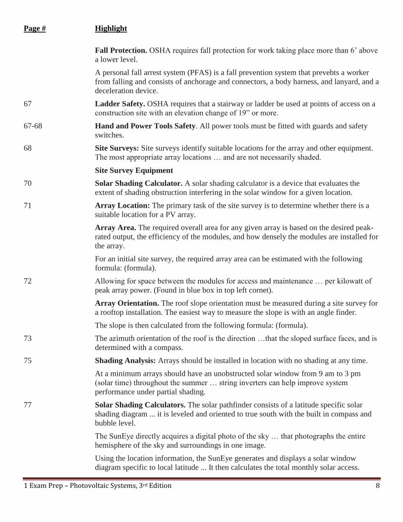
Fall Protection. OSHA requires fall protection for work taking place more than 6’ above
a lower level.
A personal fall arrest system (PFAS) is a fall prevention system that prevebts a worker
from falling and consists of anchorage and connectors, a body harness, and lanyard, and a
deceleration device.
67 Ladder Safety. OSHA requires that a stairway or ladder be used at points of access on a
construction site with an elevation change of 19” or more.
67-68 Hand and Power Tools Safety. All power tools must be fitted with guards and safety
switches.
68 Site Surveys: Site surveys identify suitable locations for the array and other equipment.
The most appropriate array locations … and are not necessarily shaded.
Site Survey Equipment
70 Solar Shading Calculator. A solar shading calculator is a device that evaluates the
extent of shading obstruction interfering in the solar window for a given location.
71 Array Location: The primary task of the site survey is to determine whether there is a
suitable location for a PV array.
Array Area. The required overall area for any given array is based on the desired peak-
rated output, the efficiency of the modules, and how densely the modules are installed for
the array.
For an initial site survey, the required array area can be estimated with the following
formula: (formula).
72 Allowing for space between the modules for access and maintenance … per kilowatt of
peak array power. (Found in blue box in top left cornet).
Array Orientation. The roof slope orientation must be measured during a site survey for
a rooftop installation. The easiest way to measure the slope is with an angle finder.
The slope is then calculated from the following formula: (formula).
73 The azimuth orientation of the roof is the direction …that the sloped surface faces, and is
determined with a compass.
75 Shading Analysis: Arrays should be installed in location with no shading at any time.
At a minimum arrays should have an unobstructed solar window from 9 am to 3 pm
(solar time) throughout the summer … string inverters can help improve system
performance under partial shading.
77 Solar Shading Calculators. The solar pathfinder consists of a latitude specific solar
shading diagram ... it is leveled and oriented to true south with the built in compass and
bubble level.
The SunEye directly acquires a digital photo of the sky … that photographs the entire
hemisphere of the sky and surroundings in one image.
Using the location information, the SunEye generates and displays a solar window
diagram specific to local latitude ... It then calculates the total monthly solar access.
1 Exam Prep – Photovoltaic Systems, 3rd Edition 9
Page # Highlight
79 Altitude Angle Method. A simple method to evaluate shading at a particular location is
by measuring or calculating the altitude angle of each obstruction.
Altitude angles can be calculated with the following formula: (formula).
80 Figure 3-23. Altitude angles can be determined using a calculator, protractor, or by
calculations from measurements.
Profile Angle Method. The profile angle is the projection of the solar altitude angle onto
an imaginary plane perpendicular to the surface of the obstruction.
The profile angle is calculated with the following formula: (formula).
81 Figure 3-25. The profile angle is the projection of the solar altitude … This angle is used
to calculate the length of shadows.
82 Figure 3-26. Profile angle calculations are particularly useful … at certain time of the
day.
83 Accessibility. Accessibility to rooftop mounted PV arrays is a critical concern for
firefighters in allowing access pathways and ventilation opportunities on the roof in the
event of a fire.
83-84 Roofing Evaluation. Arrays are installed on many types of roof surfaces … The
expected life of the roof covering is also very important.
84 A primary concern is the condition of the roof covering, particularly its weather sealing.
For conventional asphalt shingles, deterioration includes … Asphalt shingles generally
are the least expensive, but have the shortest life.
For slate, clay, or concrete roof tiles problems include … Slate and tile roofs have a long
expectancy, but are moderately expensive.
Metal roofing also has a long life but is expensive. Signs of aging include … and pitting
on aluminum roofs.
The thickness of the roof decking dictates the appropriate length of the fasteners needed
to install the array. The thickness can usually be determined by looking under the eave
drip edge or flashing along the edge of the roof.
85 Structural Support. First, a visual inspection determines the flatness of the roof surface.
A string … dips wherever there is a gap between the string and the roof surface.
Next, the installer should walk carefully across the roof and check for movement of the
surface.
Arrays must be securely attached to the roof’s underlying structural members in order to
resist wind and other loads.
1 Exam Prep – Photovoltaic Systems, 3rd Edition 10
Page # Highlight
Electrical Assessment.
86 Most inverters can be installed either indoors or outdoors, as long as they have the
appropriate enclosure ratings … Inverters should be kept out of direct sunlight or other
environments that can raise operating temperatures.
Batteries should be installed within well-ventilated and protective enclosures.
Site Layout Drawings: Site layout diagrams and sketches should identify the shape and
dimensions of the structure, and the locations between major system components.
Energy Audit: Some PV installations require a detailed electrical load analysis …
average daily time of use, and total energy consumed.
87 Figure 3-32. A site layout drawing shows basic building dimensions and locations of
major components.
Figure 3-33: A load analysis is part of an energy audit … sizing PV systems using
batteries.
90 Installation Planning: The installer completes the final design’ prepares construction
drawings … to complete the installation in the most efficient and timely manner.
98 Modules and Array: An array consists of individual PV modules that are electrically
connected to produce a desired voltage, current, and power output. Modules and arrays
produce DC voltage … or can be converted to AC power by inverters.
Energy Storage Systems: Energy storage systems balance energy production and
demand.
Batteries, particularly lead-acid types are by far the most common means of energy
storage in PV systems.
99 Batteries. A battery bank is a group of batteries connected together with … Batteries in a
PV system are charged by the array when sunny and discharged by loads when cloudy or
at night.
Batteries provide short surge currents for loads with special starting requirements, which
PV modules cannot provide.
Flywheels. Flywheels are large, spinning rotors and are commonly used to transfer power
from motors and engines to pumps and other rotational loads.
100 Supercapicitors. Capacitors store energy in an electrical field developed by two
oppositely charged a parallel conductive plates separated by a dielectric material.
Supercapacitors are a suitable replacement for batteries in many low-power applications.
1 Exam Prep – Photovoltaic Systems, 3rd Edition 11
Page # Highlight
Power Conditioning Equipment: Power conditioning equipment converts, controls, and
otherwise processes DC power produced by a PV array to make the power compatible
with other power loads.
101 Inverters. An inverter is a device that converts DC power to AC power. In PV systems,
inverters convert DC power from battery banks or PV arrays to AC power for AC loads.
to export to the utility grid.
Battery-based inverters are used in stand-alone PV systems and operate directly from the
battery banks to their input source.
The AC output is typically 120V or 240V single-phase power, with power ratings from a
few hundred watts to over 10 kW.
102 Utility-interactive inverters draw power directly from PV arrays and operate in parallel
with the utility grid.
Typically output voltages are 120 V or 240 V single-phase units with power outputs up to
10 k W, while 208 V and 480 V three-phase … a few MW. Utility-interactive inverter
output is determined by the DC input from the array, unlike battery based inverters.
Charge Controllers. A charge controller is a device that regulates battery charge by
controlling the charging voltage and/or current from a DC power source, such as a PV or
array.
103 Charge controllers regulate battery charging by terminating or limiting the charging
current when the battery bank reaches a full state of charge.
Rectifiers and Chargers. A rectifier is a device that converts AC power to DC power. A
charger is a device that combines a rectifier with filters, transformers, and other
components to condition DC power for the purpose of battery charging.
DC-DC Converter. A DC-DC converter is a device that converts DC power from one
voltage to another.
Maximum Power Point Trackers. A maximum power tracker (MPPT) is a device or
circuit that introduces electronics to continually adjust the load on a PV device under
changing temperature … to keep it operating at its maximum power point.
104 Electrical Loads. An electrical load is any type of device, equipment, or appliance that
consumes electricity.
105 DC Loads.
The most common DC Loads used in PV systems are lighting fixtures and motors for
fans and pumps. Many DC loads operate at 12 V, 24 V, and 48 V.
AC Loads. Most residential and commercial loads are AC loads, including refrigerators,
air conditioners, televisions, lighting, and motors.

1 Exam Prep – Photovoltaic Systems, 3rd Edition 12
Page # Highlight
Balance-of System Components: Balance-of-system components are all the remaining
electrical and mechanical components needed to integrate and assemble the major
components of a PV system.
Mechanical BOS Components. Mechanical BOS components include fasteners,
brackets, enclosures, racks, and other structural support.
Electrical BOS Components. Electrical BOS components include conductors, cables,
conduits, junction boxes, enclosures, connectors, and terminations needed to make circuit
connections between modules, controllers … and equipment.
106 Electrical Energy Sources: Besides the PV array, an electric utility grid is the source of
electricity that is far by far most commonly connected to PV systems.
110 PV System Configurations: The simplest PV system configuration is a PV module or
array connected directly to a DC load.
Stand-Alone Systems. A stand-alone system is a type of PV system that operates
autonomously and supplies power to electrical loads independently of the electric utility.
Stand-alone PV systems are most popular for meeting small to intermediate size electrical
loads.
Direct-Coupled System Systems. A direct –coupled PV system is a type of stand-alone
system where the output of a PV module or array is directly connected to a DC load.
Direct-coupled PV systems are common for pumping potable water and agricultural
water supplies.
DC motors are the most common loads for direct-coupled systems.
While direct-coupled systems are the simplest form of any PV system in terms of
equipment, they are perhaps the most complex to design properly dues to lack of energy
storage or system control.
111 Self-Regulated Systems. A self-regulating PV system is a type of stand-alone PV system
that uses no active control systems to protect the battery, except through careful design
and component sizing.
To protect the battery from over charge, the battery system must be oversized in relation
to the size of the array.
Charge-Controlled Systems. If loads are variable or uncontrolled, charge control is
required to prevent damage to the battery from overcharge or discharge. Charge control
typically involves … to prevent overcharge.
Charge control is required by the NEC if the maximum array current is equal to 3% or
more of the rated battery capacity.
113 Utility-Interactive Systems. A utility-interactive system is a PV system that operates in
parallel with and is connected to the electric utility grid.

1 Exam Prep – Photovoltaic Systems, 3rd Edition 13
Page # Highlight
These systems are the simplest and least expensive PV systems that produce AC power
because they require the fewest components and do not use batteries. The primary
component of a utility-interactive system is the inverter.
Net Metering. Net metering is a metering arrangement where any excess energy is
exported to the utility is subtracted from the amount of energy imported from it. Using
this system, energy supplied … credited to the customer at full retail value.
114 Figure 4-19. Utility-Interactive System
Dual Metering. Dual metering is the arrangement that measures energy exported to and
imported from the utility grid separately.
115 Multimode Systems. A multi-mode system is a PV system that can operate in either
utility-interactive or stand-alone mode and uses battery storage.
The key component … is the inverter, which draws DC power from the battery system
instead of the array.
Multimode systems are typically used to back up critical loads … different times of the
day in order to reduce electricity bills.
116 Figure 4-21. Multimode System
118 Hybrid Systems: A hybrid-system is a stand –alone system that includes two or more
distributed energy sources.
Hybrid systems offer several advantages over PV-only … flexibility in meeting variable
loads.
Hybrid systems are perhaps the most complex of all PV system in terms of equipment,
system design, and installation.
A DC bus hybrid system is a hybrid system that combines … for charging the battery
bank.
An AC bus hybrid system is a hybrid system that supplies loads with AC power from
multiple energy sources.
Figure 4-22. Hybrid Systems
124 Photovoltaic Cells. A photovoltaic cell is a semiconductor device that converts solar
radiation into direct current electricity.
Semiconductors. A semiconductor is a material that can exhibit properties of both an
insulator and a conductor.
125 Photovoltaic Effect: The basic physical process by which a PV cell converts light into
electricity is known as the photovoltaic effect. The photovoltaic effect is the movement of
the electrons … energy above a certain level.
1 Exam Prep – Photovoltaic Systems, 3rd Edition 14
Page # Highlight
A PV cell is a thin, flat wafer consisting of a … semiconductor materials in contact with
one another.
Figure 5-3.Photovoltaic Effect
126 Cell Materials: PV cells can be produced from a variety of semiconductor materials,
though crystalline silicon is by far the most common.
Crystalline silicon (C-Si) cells currently offer the best ratio of performance …
semiconductor industry.
Gallium arsenide (GaAs) cells are more efficient than c-Si cells … space application.
A multifunction cell is a cell that maximizes efficiency … wavelengths of solar energy.
A thin-film module is a module level PV device … and make electrical connections
between cells.
A photoelectrochemical cell is a cell that relies on chemical processes to produce
electricity from light, rather than using a semiconductor.
Figure 5-4. PV Cell Material Efficiencies.
131 Current Voltage (I-V) Curves: The current-voltage (I-V) characteristic is the basic
electrical output of a PV device.
An I-V curve is the graphic representation of all possible voltage and current operating
points for a PV device at a specific operating condition.
A PV device can operate anywhere along its I-V curve, depending on the electrical lOad.
Figure 5-10. I-V Curve
Certain points on an I-V curve are used to rate module performance and are the basis for
the electrical design of arrays.
132 Open-Circuit Voltage: The open-circuit voltage is the maximum voltage on an I-V
curve and is the operating point for a PV device under infinite …and no current output.
The open-circuit voltage of a PV-device can be measured by exposing the device to
sunlight and measuring across the output terminals with a voltmeter or multimeter set to
measure DC voltage.
The open-circuit voltage of a PV device is determined by the semiconductor material
properties and temperature.
Short-Circuit Current: The short-circuit current is the maximum current on a n IV-
curve and is the operating point for a PV device …and no voltage output.
132-133 The short-circuit current of a PV device is used to determine maximum circuit design …
measuring current with an ammeter or multimeter.

1 Exam Prep – Photovoltaic Systems, 3rd Edition 15
Page # Highlight
133 Figure 5-12. Short-Circuit Current Measurement
134 The current of a PV device is directly proportional to the surface area … doubling the
solar irradiance on the device surface will double the current.
Maximum Power Point: The maximum power point is the operating point on an IV-
curve where the product of current and voltage is at a maximum.
The maximum power voltage is the operating voltage on an I-V curve … Maximum
power is calculated using the following formula: (formula).
135 Maximum power voltage and current can be measured only while the PV device is
connected to a load that operates the device at maximum power.
Efficiency. The efficiency of PV devices compares the solar power input to the electrical
power output.
136 Efficiency is expressed as a percentage and is calculated with the following formula:
(formula).
Operating Point: PV cells operate most efficiently at their maximum power points.
137 The electrical load resistance required to operate a PV device at any point can be
calculated … the formula is: (formula).
138 Solar Irradiance Response: Changes in solar irradiance have a small effect on voltage
but a significant effect on the current output of PV devices. The current of a PV device
increases proportionally with increasing solar irradiance.
139 Temperature Response: For most types of PV devices, high operating temperatures
significantly reduce voltage output.
139-140 Cell Temperature. The cell temperature of a PV device refers to the internal temperature
at the p-n junction. Cell temperature is influenced by …. Cell temperature can be
estimated by either directly measuring the cell or module surface temperature or applying
the temperature rise coefficient.
140 Temperature Coefficients. A temperature coefficient is the rate of change in voltage,
current, or power output from a PV device due to changing cell temperature.
142-143 Modules and Arrays: A module is a PV device consisting of a number of individual
cells connected electrically, laminated, encapsulated, and packaged into a frame.
An array is a complete PV power generating unit consisting of a number of individual
electrically and mechanically integrated modules with structural supports, trackers, or
other components.
144 Electrical Connections

1 Exam Prep – Photovoltaic Systems, 3rd Edition 16
Page # Highlight
Series Connections. Individual cells are connected in series by soldering thin metal
strips … Modules are connected in series with other modules by connecting conductors
… to the positive terminal of another module.
Only PV devices having the same current output should be connected in series.
PV devices with different voltage outputs can be connected in series without loss of
power as long as each device has the same current output.
Figure 5-25. Series Connections
146 The maximum number of modules that can be connected in a series string … voltage
rating of the modules and other components.
Parallel Connections: Parallel connections involve connecting the positive terminals …
together at common terminals or busbars.
151 Module Selection: Electrically, the voltage, current, and power output values are the
most important considerations because they define the total number of modules needed to
meet the desired energy production requirement.
152 On the physical side, among factors that may be considered for module selection are …
the means for structural attachments.
Arrays: Groups of modules are combined electrically and mechanically … The result is
a complete array that integrates all the modules into a single power-generating unit.
Most complete arrays are monopole arrays. A monopole array is an array that has one
positive terminal and one negative terminal.
160 A cell is the basic unit in a battery that stores electrical energy in chemical bonds and
delivers this energy through chemical reactions.
161 Steady-State: A cell or battery that is not connected to a load or charging circuit is at
steady-state. Steady-state is an open-circuit condition where essentially no electrical or
chemical changes are occurring.
The open-circuit voltage is the voltage of a battery or cell when it is at steady-state. The
open-circuit voltage of a fully charged lead-cell is about 2.1 V.
162 Capacity: Capacity is commonly expressed in ampere-hours (Ah), but can also be
expressed in watt-hours (Wh).
Discharging
163 State of Charge (SOC). The state of charge (SOC) is a percentage of energy remaining r
in a battery compared to its fully charged capacity.
Depth of Discharge (DOD). Depth of discharge (DOD) is the percentage of energy
withdrawn from a battery compared to its fully charged capacity.

1 Exam Prep – Photovoltaic Systems, 3rd Edition 17
Page # Highlight
The depth of discharge and state of charge of a battery add of to 100%.
164 Allowable DOD. The allowable depth of discharge is the maximum percentage of total
capacity that is permitted to be withdrawn from a battery.
Autonomy. Autonomy is the amount of time a fully charged battery system can supply
power to system loads without further charging.
Charging. A cycle is a battery discharge followed by a charge.
165 Charge rate is the ratio of nominal battery capacity to the charge time in hours.
167 Overcharge is the ratio of applied charge to the resulting increase in battery charge.
169 Battery Life: Battery life is expressed in terms of cycles or years.
170 Battery Types. A primary battery is a battery that can store and deliver electrical energy
but cannot be recharged.
A secondary battery is a battery that can store and deliver electrical energy and can be
charged by passing a current … to the discharge current.
171 Battery Classifications
172 Flooded-Electrolyte Batteries
Captive-Electrolyte Batteries
173 Lead-Acid Batteries
174 Nickel-Cadmium Batteries
175 Battery Systems
Battery Selection: Considerations includes lifetime, deep cycle … overcharge, and
maintenance requirements.
Battery Banks: A battery bank is a group of batteries connected together with series
and/or parallel connections to provide a specific voltage and capacity.
176 Series Connections. Batteries are first connected in a series string by connecting the
negative terminal of one battery, to the positive terminal of the next battery, in order to
build voltage.
For batteries of similar capacity and voltage connected on series, the circuit voltage …
circuit capacity is the same as the capacity of the individual batteries.
177 Parallel Connections. Batteries are connected in parallel by connecting all the positive
terminals together and all the negative terminals together.
1 Exam Prep – Photovoltaic Systems, 3rd Edition 18
Page # Highlight
The current of the parallel circuit is the sum of the current from the individual batteries.
The voltage across the circuit … the sum of the capacities of each battery. If batteries or
cells with different capacities … limited by the lowest capacity battery.
179 Battery Installation
Battery Bank Voltage: Battery banks installed in dwellings must be less than 50 V
nominal … This usually limits the voltage of lead-acid batteries to no more than 48 V
nominal.
180 Grounding: Battery systems over 48 V are permitted to be ungrounded but have several
requirements. The PV array … overcurrent protection for each ungrounded conductor.
Wiring Methods: Battery systems are permitted to use flexible conductors of 2/0 AWG
and larger.
Conductor insulation types RHW and THW also meet the requirements for most battery
installations in PV systems.
188 Charge Controller Features: A charge controller is a device that regulates battery
charge by controlling … from a DC power source, such as a PV array. A charge
controller in a PV systems maintains … overdischarge by system loads.
Battery Charging: Charge controllers manage the array current delivered to a battery
Charge acceptance is the ratio of the increase in battery charge to the amount of charge
supplied to the battery.
190 Overcharge Protection: Overcharge is the condition of a fully charged battery … A
charge controller protects a battery from overcharge through charge regulation.
According to the NEC, any PV system employing batteries shall have equipment to
control … This equates to a maximum charge rate of C/33.
191 Overdischarge Protection: Overdischarge is the condition of a battery state of charge
declining to the point where it can no longer supply discharge current … without
damaging the battery.
A charge controller protects a battery from overdischarge through load control,
disconnecting … reaches a low voltage condition.
193 Charge Controller Types
Shunt Charge Controllers: A shunt charge controller is a charge controller that limits
charging current to a battery system by short-circuiting the array.
194 Series Charge Controllers: A series charge controller is a charge controller that limits
charging current to a battery system by open-circuiting the array.
196 Maximum Power Point Tracking Charge Controllers: A maximum power point
tracking charge controller is a charge controller that operates the array … as well as
regulates the battery charging.
1 Exam Prep – Photovoltaic Systems, 3rd Edition 19
Page # Highlight
Diversionary Charge Controllers: A diversionary charge controller is a charge
controller that regulates charging current … to an auxiliary load.
197 Hybrid System Controllers: A hybrid system controller is a controller with advanced
features for managing multiple energy sources.
A principle feature of some hybrid controllers is the additional ability to start and control
an engine generator.
198 Ampere-Hour Integrating Charge Controllers: An ampere-hour integrating charge
controller … based on a preset amount of overcharge.
Charge Controller
199 Charge Controller Setpoints: A charge controller setpoint is a battery condition,
commonly the voltage, … switching functions.
Charge Regulation Setpoints
200 Load Control Setpoints
205 Charge Controller Installation
Figure 7-19: Charge Controller Selection Criteria
206 Location: To minimize their operating temperature, charge controllers should be
installed out of direct sunlight and with unobstructed airflow around the heat sinks.
209 Self-regulating PV Systems: A self-regulating PV system is a type of stand-alone PV
system that uses … component sizing.
Self-Regulating PV systems must be designed so that the battery is never overcharged or
discharged under any operating conditions.
210-211 Battery and Array Sizing: Any PV system with batteries must employ a charge control
whenever the charge rate exceeds C/33.
218 AC Power: Direct current (DC) is electrical current that flows in one direction, either
positive or negative.
PV modules, and some other power generating technologies, produce DC power.
However … Alternating current (AC) is electrical current that changes between positive
and negative directions.
Waveforms: A waveform is the shape of an electrical signal … used to represent
changing electrical current and voltage.
220 Three-Phase AC Power: Three-phase AC power includes three separate voltage and
current waveforms occurring simultaneously 120 apart.
223 Power Factor. True factor is the product of in-phase voltage and current waveforms and
produces useful work … represented in units of watts (W).

1 Exam Prep – Photovoltaic Systems, 3rd Edition 20
Page # Highlight
224 Reactive power is the product of out-of-phase voltage and current waveforms and results
in no net power flow.
Power factor is the ratio of true power to apparent power and describes … Apparent
power is a combination of true and reactive power and is given in units of volt-amperes
(VA).
Inverters: When a PV system must supply power for AC loads, an inverter is required.
An inverter is a device that converts DC power to AC power.
Inverters provide convenience by being able to integrate a PV system with existing
electrical systems.
Static (solid-state) inverters change DC power to AC power using electronics and have
no moving parts.
Inverters used in PV systems are exclusively static inverters.
226 Stand-Alone Inverters: Stand-alone inverters are connected to batteries as the DC
power …independently of the PV array and the utility grid.
Utility-Interactive Inverters: Utility-interactive PV inverters are connected to, and
operate in parallel with, the electric utility grid.
229 Multimode Inverters: Multimode inverters can operate in either interactive or stand-
alone (though not simultaneously).
231 Square Wave Inverters
233 Power Conditioning Units: The physical enclosure that is referred to as an inverter …
Power conditioning units perform one or more power processing …and maximum point
tracking.
234 Rectifiers: A rectifier is a device that converts AC power to DC power. Rectifiers are
used in battery chargers and DC power supplies operating from AC power.
Transformers: A transformer is a device that transfers energy from one circuit to
another through magnetic coupling.
Transformers cannot convert between DC and AC … or change the frequency of an AC
source.
235 DC-DC Converter: A DC-DC converter is a device that changes DC power from one
voltage to another.
Many PV inverters use DC-DC converters to change the DC input from low voltage to
high voltage prior to the power-inverting process.

1 Exam Prep – Photovoltaic Systems, 3rd Edition 21
Page # Highlight
Maximum Power Point Trackers: A maximum power point tracker (MPPT) is a device
or circuit … to keep it operating at its maximum power point .. all interactive inverters
include MPPT circuits.
236 Power Ratings. For an interactive inverter, the output power rating limits the power it
can handle at the its DC input, which limits the size of the PV array.
Temperature Limitations. Solid-state switching devices are capable of handling only so
much current before they overheat and fail. Parallel switching devices in the design
increases the power rating of an inverter.
237 Temperature is the primary limiting factor for inverter power ratings.
Interactive inverters control high temperatures by limiting the array power delivered to
the inverter.
Voltage Ratings
AC Output. For interactive inverters, AC voltage output must be maintained at -10% to
+5% of the nominal system voltage. In the case of nominal output, this range is from
108V to 126 V.
238 DC Input. DC input voltage ratings are based on the operating characteristics of wither a
battery bank or a PV array.
The required array voltage increases with increasing grid voltage … to permit MPPT
operation.
The DC voltage from the array is also affected by ambient temperature which
complicates sizing.
239 Frequency Rating: For nominal 60 Hz operation the, the AC output frequency must be
maintained between 59.3 Hz and 60.5 Hz.
Current Ratings: For the DC side, current ratings limit the PV array or battery current
that can be applied to the inverter. On the AC side, current ratings … output for
interactive inverters.
240 Efficiency: Inverter efficiency is the ratio of an inverter’s AC power output to its DC
power input.
Inverter efficiency is calculated with the following formula: (formula).
Inverter efficiency is primarily affected by the inverter load. In stand-alone, the AC load
defines the inverter load, and for interactive inverters the PV array defines the load.
248 Sizing Methodologies: 236 Power Ratings. For an interactive inverter, the output
power rating limits the power it can handle at the its DC input, which limits the size of
the PV array.

1 Exam Prep – Photovoltaic Systems, 3rd Edition 22
Page # Highlight
Temperature Limitations. Solid-state switching devices are capable of handling only so
much current before they overheat and fail. Parallel switching devices in the design
increases the power rating of an inverter.
237 Temperature is the primary limiting factor for inverter power ratings.
Interactive inverters control high temperatures by limiting the array power delivered to
the inverter.
Voltage Ratings
AC Output. For interactive inverters, AC voltage output must be maintained at -10% to
+5% of the nominal system voltage. In the case of nominal output, this range is from
108V to 126 V.
238 DC Input. DC input voltage ratings are based on the operating characteristics of wither a
battery bank or a PV array.
The required array voltage increases with increasing grid voltage … to permit MPPT
operation.
The DC voltage from the array is also affected by ambient temperature which
complicates sizing.
239 Frequency Rating: For nominal 60 Hz operation the, the AC output frequency must be
maintained between 59.3 Hz and 60.5 Hz.
Current Ratings: For the DC side, current ratings limit the PV array or battery current
that can be applied to the inverter. On the AC side, current ratings … output for
interactive inverters.
240 Efficiency: Inverter efficiency is the ratio of an inverter’s AC power output to its DC
power input.
Inverter efficiency is calculated with the following formula: (formula).
Inverter efficiency is primarily affected by the inverter load. In stand-alone, the AC load
defines the inverter load, and for interactive inverters the PV array defines the load.
248 Sizing Methodologies: When sizing a PV system, it is necessary to consider the energy
demand before considering the supply … The objective is to first determine the size of
the inverter, battery bank, and array that are needed to meet the requirements.
Sizing Utility-Interactive Systems: The sizing for interactive systems without energy
storage generally involves determining the maximum array power output … 80% to 90%
of the array maximum-power rating at standard test conditions (STC).
249 Figure 9-2. Interactive System Sizing
Sizing interactive systems begins with the specifications of PV module chosen for the
system.
1 Exam Prep – Photovoltaic Systems, 3rd Edition 23
Page # Highlight
The size of an interactive system is primarily limited by the space available for an array
and the owner’s budget.
250 Sizing Stand-Alone Systems: Stand-alone systems are designed to power specific on-
site loads … directly proportional to the load requirements.
Sizing stand-alone systems is based on meeting specific load requirements and involves
the following key steps: 1-4.
251 Sizing Multimode Systems: Multi-mode systems are typically sized according to the
stand-alone technology.
The stand-alone sizing methodology determines the minimum size of a multimode
system.
Sizing Hybrid Systems: The array and battery bank for a PV array and engine generator
hybrid system are sized similarly to those for a stand-alone system with three differences.
First … Finally, battery banks can be sized for a shorter autonomy period than for PV-
only stand-alone systems, also because the generator power is available on demand.
Sizing Calculations: Sizing PV systems for stand-alone operation involves four sets of
calculations. First … Finally the PV array is sized to fully charge the battery bank under
the critical conditions.
252 Load Analysis: Analyzing electrical loads is the first and most important step in PV-
system sizing. The energy consumption dictates the amount of electricity that must be
produced.
A detailed load analysis completed during the site survey lists each load, its power
demand and daily energy consumption.
253 Power Demand. Peak-power information is usually found on appliance nameplates …
peak power demand can be estimated by multiplying the maximum current by the
operating voltage.
Energy Consumption. Electrical energy consumption is based on the power demand
over time.
254 The daily energy consumption for each load is determined by the load’s power demand
multiplied by the daily operating time.
Inverter Selection. If the system includes AC loads, an inverter must be selected.
Several factors must be considered when selecting an inverter. First, … as the largest
single AC load.
Inverter voltage output is another consideration.
255 The inverter DC-input voltage must also correspond with either the array voltage or the
battery-bank voltage.

1 Exam Prep – Photovoltaic Systems, 3rd Edition 24
Page # Highlight
Inverter Efficiency. Both the AC and DC energy requirements from the load analysis are
used to determine how much total DC energy will be required.
The total amount of DC energy required by the loads is calculated using the following
formula: (formula).
256 Critical Design Analysis: Systems are sized for the worst-case scenario of high load and
low insolation.
The critical design ratio is the ratio of electrical energy demand to average insulation
during a period.
257 Array Orientation. If multiple orientations are possible, separate analyses are performed
for each orientation.
The orientations most commonly used in a critical design analysis are tilt angles equal to
the latitude.
The greater array tilt angle maximizes the received solar energy in winter months … in
summer months.
260 DC-System Voltage: This voltage dictates the operating voltage and rating for all other
connected components … inverters, and the array.
The selection of the battery-bank voltage affects system currents.
Lower current reduces the required sizes of conductors, overcurrent protection … and
other equipment.
As a rule of thumb, stand-alone systems up to 1 kW use a minimum 12 V battery-bank
voltage, which limits DC currents to less than 84A.
System Availability. System availability is the percentage of time over an average year
that a stand-alone PV system meets the system load requirements.
System availability is determined by insulation and autonomy.
Autonomy is the amount of time a fully charged battery can supply system can supply
power to the system loads without further charging.
261 Battery-Bank Sizing
Battery-Bank Required Output. Batteries for stand-alone PV systems are sized to store
enough … without further charge or energy contributions from the PV array.
Figure 9-13. Battery-Bank Sizing
262 The required battery-bank capacity is determined from electrical-energy requirements to
operate loads … The required battery-bank rated capacity is calculated using the
following formula: (formula).

1 Exam Prep – Photovoltaic Systems, 3rd Edition 25
Page # Highlight
Battery-Bank Rated Capacity. Most PV systems use deep-cycle lead-acid batteries,
which can be discharged to about 80%. This is the maximum fraction of the total rated
capacity … at any time.
Most battery rating are specified for operation at 25 C (77 F) at a certain discharge rate.
263 Using the daily operating time calculated in load analysis … average discharge rate is
calculated using the following formula: (formula).
To calculate the total rated capacity of the battery bank … The required capacity is
calculated using the following formula: (formula).
264 Battery Selection. The number of parallel battery connections should be limited to 3- 4
strings.
The nominal DC-system voltage divided by the nominal battery voltage determines the
number of batteries in a string.
265 Battery-Bank Operation. First, the daily load fraction supplied by the battery bank is
estimated.
The load fraction is the portion of load operating power that comes from the battery bank
over the course of a day.
Instead, of load-fraction estimate of 0.75 is a common rule of thumb used for most PV
systems.
With the load fraction estimate, the average battery-bank daily depth … estimated with
the following formula: (formula).
266 Array Sizing: For stand-alone systems, the array must be sized to produce enough
electrical energy to meet … while accounting for normal system losses.
Figure 9-18. Array Sizing
Required Array Output: The required array current is calculated using the following
formula: (formula).
267 Array Rated Output
268 Soiling is the acumination of dust and dirt on an array surface that shades the array and
reduces electrical output.
The rated array maximum-power current is calculated using the following formula:
(formula).
High temperature reduces array voltage output.
The rated array maximum-power voltage is calculated using the following formula:
(formula).

1 Exam Prep – Photovoltaic Systems, 3rd Edition 26
Page # Highlight
269 Module Selection. For each module, three parameters are needed for sizing: the
maximum power … and the maximum-power (operating) voltage.
The number of parallel strings of modules required … rounding up to the next whole
number.
The number of series-connected modules in each string is determined … rounding up to
the next whole number.
The rated array maximum power is calculated by multiplying the rated module maximum
power by the total number of modules.
278 The installed nominal operating cell temperature (INOCT) is the estimated temperature
of a PV array operating in a specific mounting system design.
281 Array Mounting Systems: the simplest most common type of array mount for modules
is the fixed-tilt type. A fixed-tilt mounting system … An adjustable mounting system is
an array mounting system that permits the manual adjustment of the tilt.
Building Mounting Systems
Direct Mounts. A direct mount is a type of …finished rooftop or other building surface.
Temperature-rise coefficients for direct mounts can be as high as 40 to 50 C/kW/ .
282 Roof-Rack Mounts. A rack-mount is a type of fixed- or adjustable-tilt array mounting
system with a triangular-shaped structure to increase the tilt angle of the array.
INOCT for rack-mounted arrays is the lowest among building mounting systems … 15 to
20 C/kW/
Standoff Mounts. A standoff mount is a type of fixed-tilt array mounting system where
modules … slightly above the roof surface.
283 In general, standoff mounts should be installed between 3” to 6” from the top of the
module to the roof surface … are around 20 to 30 C/kW/
284 Ground Mounting Systems
286 Sun-Tracking Systems: A sun-tracking mount is an array mounting system that
automatically orients the array to the position of the sun.
287 An active tracking mount is an array mounting system that uses electric motors and gear
drives to automatically direct the array toward the sun.
288 A passive track mount is an array mounting system that uses nonelectrical means to
automatically direct an array toward the sun.
Mechanical Integration

1 Exam Prep – Photovoltaic Systems, 3rd Edition 27
Page # Highlight
Materials. Any material used should match the expected 20- to 30-year service lifetime
of the overall system.
Stainless steel alloys recommended for most fasteners.
Aluminum structural alloys 6061 and 6063 ….and relatively inexpensive.
289 Structural Loads: Arrays and their attachment points must be designed and installed to
withstand the forces from a combination of structural loads. A design load is a calculated
structural load used to evaluate the strength of a structure to failure.
290 Dead Load: A dead load is a static structural load due to the weight of permanent
building members, supported structure, and attachments.
Live Load: A live load is a dynamic structural load due to …occupying the structure.
291 The basic wind speed is the maximum value of a 3 sec gust at 33’ elevation, which is
used in wind load calculations.
294 Attachment Methods
295 Mounting system attachments should be made through the roof cladding and into
building structural members, such as rafters.
Lag Screws. Lag screws are the most common fastenings for attaching array mounts to
rooftops.
Figure 10-22. Allowable Withdrawal Loads
309 Voltage and Current Requirements
310 Maximum PV Circuit Voltage: The maximum voltage of a PV source circuit is
determined … lowest expected ambient temperature.
311 The maximum PV source-circuit or output-circuit voltage is calculated using the formula:
(formula).
312 Maximum PV Circuit Currents: For PV source circuits, the maximum current is 125%
of the sum … parallel-connected modules.
For PV output circuits, the maximum current is the sum of the maximum currents of the
parallel-connected source circuits.
Maximum Inverter input Current: Maximum inverter input current is calculated with
the following formula: (formula).
313 Maximum Inverter Output Current: The maximum current for the inverter output is
equal to … output current rating.
Conductors and Wiring Methods:

1 Exam Prep – Photovoltaic Systems, 3rd Edition 28
Page # Highlight
314 Figure 11-4. Conductor Sizes
315 Figure 11-5. National Ampacities of Insulated Cooper Conductors
317 Voltage Drop. Voltage drop and the associated percentage of the voltage drop of
conductors are calculated using Ohm’s law: (formula).
318 Conductor Insulation
319 Figure 11-10. Recommended Insulation Types for PV Systems
321 Wiring Connections
322 The following are basic requirements for terminating electrical conductors: (6 bullets).
Module Connectors. These connectors must meet the following five requirements from
Section 690.33: (5 bullets).
324 Junction Boxes
328 Overcurrent Protection
329 Overcurrent Protection Devices. Overcurrent protection devices include fuses and
circuit breakers.
330 PV System Overcurrent Protection
331 Circuits must be protected from every source of power.
Every undergrounded conductor must be protected.
Array Overcurrent Protection. Generally, all undergrounded array conductors must
include overcurrent protection. The grounded conductors must not normally include
overcurrent protection.
332 Inverter-Output Overcurrent Protection.
Figure 11-25. Overcurrent protection in the inverter output circuit depends …
accomplished by using circuit breakers or fused disconnects.
333 Disconnects: A disconnect is a device used to isolate equipment and conductors from
sources of electricity from the purpose of installation, maintenance, or service.
334 Array Disconnects: A disconnect must be provided to isolate all current-carrying
conductors … in a building or structure.
AC Disconnects: A disconnect must also be installed on the AC side of the PV system to
isolate the system from the rest of a building’s electrical system.
335 Equipment Disconnects: If equipment is connected to one or more power source, each
power source must have disconnecting means.

1 Exam Prep – Photovoltaic Systems, 3rd Edition 29
Page # Highlight
Grounding
336 AC Grounding
DC Grounding. The DC grounding connection must be made at a single point on the
PV output circuit, usually within the inverter.
337 AC and DC Grounding.
Figure 11-30. The DC grounding system and the AC grounding system must be …
require a separate grounding electrode system.
338 Ground-Fault Protection. Ground-fault protection is the automatic opening of
conductors involved in a ground fault.
340 Equipment Grounding.
341 Figure 11-35. Grounding Conductor Sizing
343 Surge Arrestors: A surge arrestor is a device that protects electrical devices from
transients (voltage spikes).
345 Battery Systems.
Battery Banks Less Than 50 V
Battery Banks Greater Than 50 V: Battery systems of greater than 48 V must include
a disconnect to divide the system into segments of 48 V or less for maintenance.
346 Charge Control: In the case of self-regulated systems, charge control is accomplished
through careful sizing and the matching of the array to the battery bank. Most systems …
must include active means of charge control.
Diversion loads are commonly used for charge control …The loads voltage rating must
be greater than the maximum battery voltage … the power rating must be at least 150%
of the array’s power rating.
354 Utility-Interactive Systems. The most common type of utility interactive PV system is
one that does not use energy storage. The array is connected to the DC input of the
utility- interactive inverter.
When on-site power demand exceeds the supply from the PV system, the power is drawn
from the utility.
Multimode Systems. Multimode systems are interactive systems that include battery
storage … water pumps, or lighting.
The inverters serve the on-site loads or send excess power back to the grid while the array
keeps the battery bank fully charged.

1 Exam Prep – Photovoltaic Systems, 3rd Edition 30
Page # Highlight
355 Multimode inverters are programmed to supply electrical loads … minimizing the use of
high-priced utility energy.
358 Interconnection Concerns.
Islanding. Islanding is the undesirable condition where a distributed-generation power …
continues to supply power to the utility grid during a utility outage.
360 Point of Connection: The point of connection is the location at which the interactive
distributed-generation system makes its interconnection with the electric utility system.
Load-Side Interconnections. The NEC permits load-side connection for utility
interactive inverters … following the seven conditions are satisfied: 1 -7.
363 Supply-Side Interconnections. When PV systems are too large to interconnect on the
load side … a supply side interconnection must be used.
366 Utility Interconnection Policies
383 Permitting
Permit Applications. Permit applications for PV systems should contain site drawing s
… and array mounting information.
Site Drawings. A simple drawing of the site should indicate the locations of major PV
system components … and other features.
Electrical Diagram
385 Figure 13-5. Permit applications usually require either a one-line or a three-line electrical
diagram.
Array Mounting Design. Most permit applications for PV systems require descriptions
… and that the array will be well secured.
387 Inspection
388 Working Space: PV system inspections also ensure that there is adequate access and
safe working space around all electrical equipment.
389 Live Parts. Live parts are energized conductors and terminals. Live parts must be
protected … 50 V or more.
390 Labels and Marking
400 System Functional Testing
Verification Testing
402 System Performance Testing
404 Maintenance
1 Exam Prep – Photovoltaic Systems, 3rd Edition 31
Page # Highlight
405 Array Maintenance
408 Battery Maintenance
413 Monitoring
417 Troubleshooting
426 Incentives
431 Cost Analysis
433 Life-Cycle Costs
438 Life-Cycle Cost Analysis: The life-cycle cost for any energy system is the sum of the
present values … This is represented in the following formula: (formula).