Embed Size (px)
Citation preview

1
Electronic Circuits
COMMON EMITTER CIRCUITS

2
Electronic Circuits
AMPLIFIERS CAN BE CLASSIFIED AS EITHER:
VOLTAGE AMPS
POWER AMPS

3
Electronic Circuits
Voltage amplifiers are used to increase the level of an input signal.
The amp may accept an input voltage of a few millivolts p-p and amplify the voltage to several volts p-p, then apply that voltage to another circuit or device.

4
Electronic Circuits
Power amps are used to increase the power level of an input signal.
The power amp delivers a lot of power to a load by accepting a relatively low input current and producing a high output current.
A low resistance load is necessary to develop a high output current.

5
Electronic Circuits
When using transistors as the principle controlling element in an amp circuit, three circuit configurations are possible.
When using transistors as the principle controlling element in an amp circuit, three circuit configurations are possible.

6
Electronic Circuits
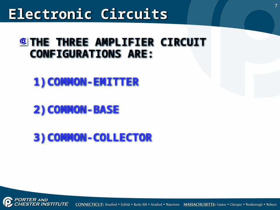
There are three common amplifier circuit configurations that were addressed in semi-conductors.
WHAT ARE THE 3 TRANSISTOR CIRCUITS?
7
Electronic Circuits
THE THREE AMPLIFIER CIRCUIT CONFIGURATIONS ARE:
1) COMMON-EMITTER
2) COMMON-BASE
3) COMMON-COLLECTOR

8
Electronic Circuits
The three circuit configurations are formed by using the emitter, base or collector lead as the common lead.
THE COMMON LEAD IS CONNECTED TO CIRCUIT COMMON OR GROUND.

9
Electronic Circuits

10
Electronic Circuits
THE COMMON EMITTER CIRCUIT IS THE MOST COMMONLY USE CIRCUIT
CONFIGURATION.
This configuration is often used to increase the level of an input voltage.
The voltage gain is expressed as a ratio:

11
Electronic Circuits
Both voltage and power amps can also be classified by frequency:
DC AMPLIFIER - 10HZ OR LESSAUDIO AMPVIDEO AMPRF AMPIF AMP - INTERMEDIATE FREQUENCY
12
Electronic Circuits
In some cases, one amplifier stage must be joined or coupled with another amplifier circuit to provide a higher overall gain.
When we connect multiple amplifier circuits together we refer to it as amplifier coupling.

13
Electronic Circuits
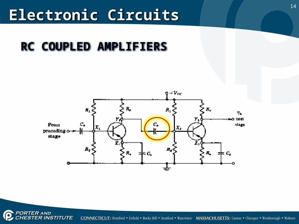
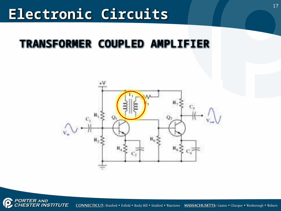
THEY ARE FOUR BASIC COUPLING METHODS USED:
1. RC COUPLING- RESISTANCE CAPACITANCE.
2. IMPEDANCE COUPLING- USES AN INDUCTOR.
3. DIRECT COUPLING.4. TRANSFORMER COUPLING.
14
Electronic Circuits
RC COUPLED AMPLIFIERS

15
Electronic Circuits
IMPEDANCE COUPLED AMPLIFIER

16
Electronic Circuits
DIRECT COUPLE AMPLIFIER
17
Electronic Circuits
TRANSFORMER COUPLED AMPLIFIER