Embed Size (px)
Citation preview
1
EE5900 Advanced Embedded System For Smart Infrastructure
Energy Efficient Scheduling
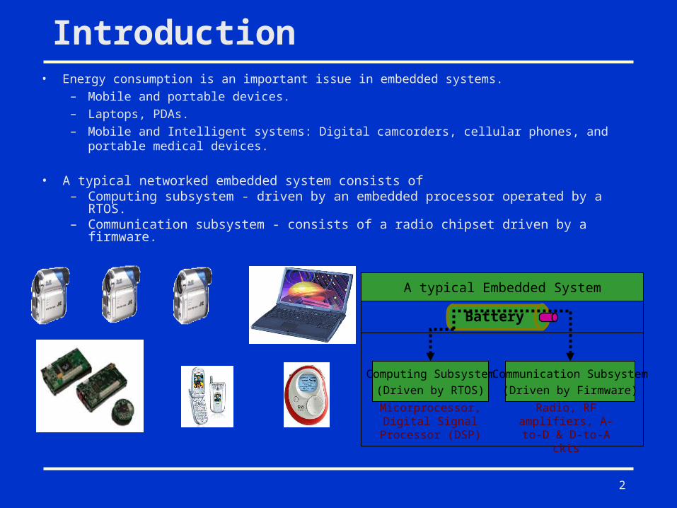
• Energy consumption is an important issue in embedded systems. – Mobile and portable devices.– Laptops, PDAs.– Mobile and Intelligent systems: Digital camcorders, cellular phones, and portable
medical devices.
• A typical networked embedded system consists of– Computing subsystem - driven by an embedded processor operated by a RTOS. – Communication subsystem - consists of a radio chipset driven by a firmware.
Micorprocessor, Digital Signal
Processor (DSP)
Radio, RF amplifiers, A-to-D & D-to-A ckts
A typical Embedded System
Battery
Computing Subsystem
(Driven by RTOS)
Communication Subsystem
(Driven by Firmware)
Introduction
2
3
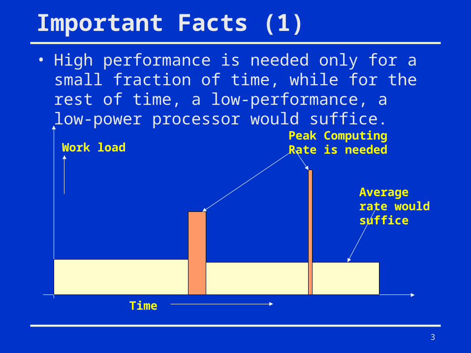
Important Facts (1)
• High performance is needed only for a small fraction of time, while for the rest of time, a low-performance, a low-power processor would suffice.
Time
Work loadPeak Computing Rate is needed
Average rate would suffice
4
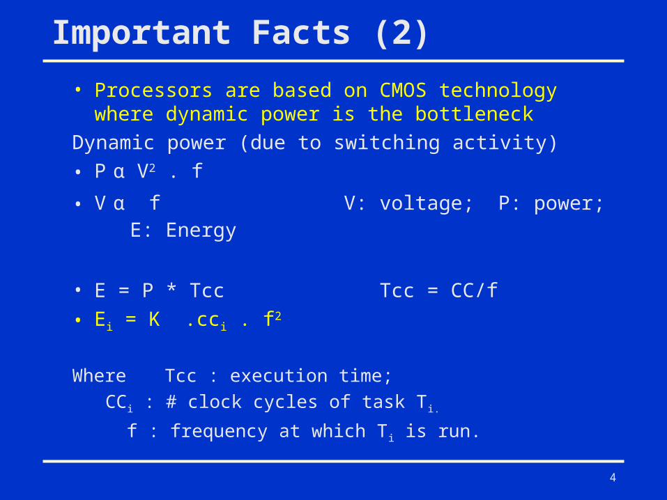
Important Facts (2)
• Processors are based on CMOS technology where dynamic power is the bottleneck
Dynamic power (due to switching activity)
• P α V2 . f
• V α f V: voltage; P: power; E: Energy
• E = P * Tcc Tcc = CC/f
• Ei = K .cci . f2
Where Tcc : execution time;
CCi : # clock cycles of task Ti.
f : frequency at which Ti is run.
5
Variable Voltage Processors
• Modern processors operate at multiple frequency levels.– Crusoe Processor: Transmeta Corporation– PowerNow! Technology: AMD– Intel XScale: Intel
• Higher the frequency level higher the energy consumption
6
Dynamic Voltage Scaling (DVS)
• DVS scales the operating voltage of the processor along with the frequency.
• Since energy is proportional to f2 , DVS can potentially provide significant energy savings through frequency and voltage scaling.
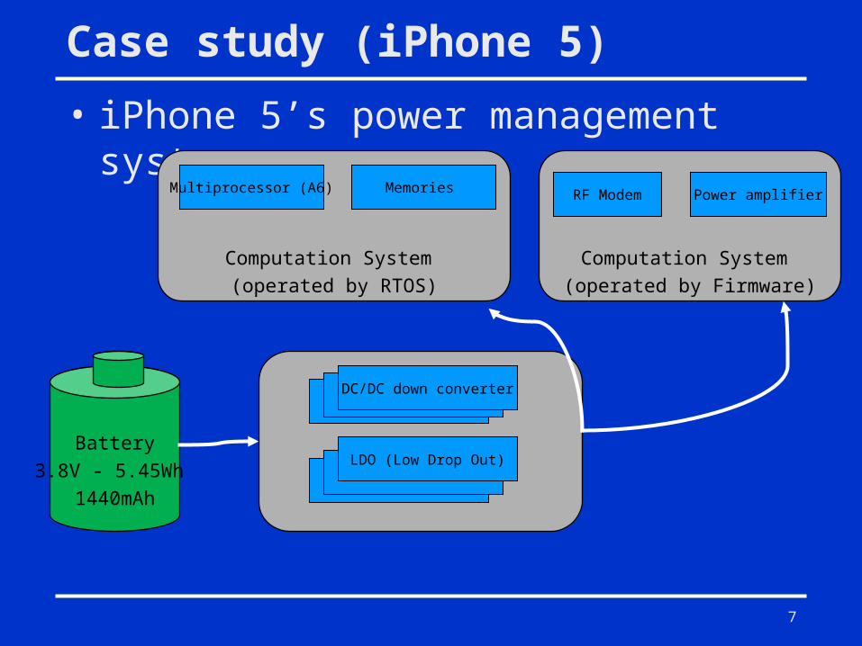
Case study (iPhone 5)
• iPhone 5’s power management system
7
Battery
3.8V - 5.45Wh
1440mAh
Computation System
(operated by RTOS)
Multiprocessor (A6)
Computation System
(operated by Firmware)
DC/DC down converter
LDO (Low Drop Out)
Memories RF Modem Power amplifier
8
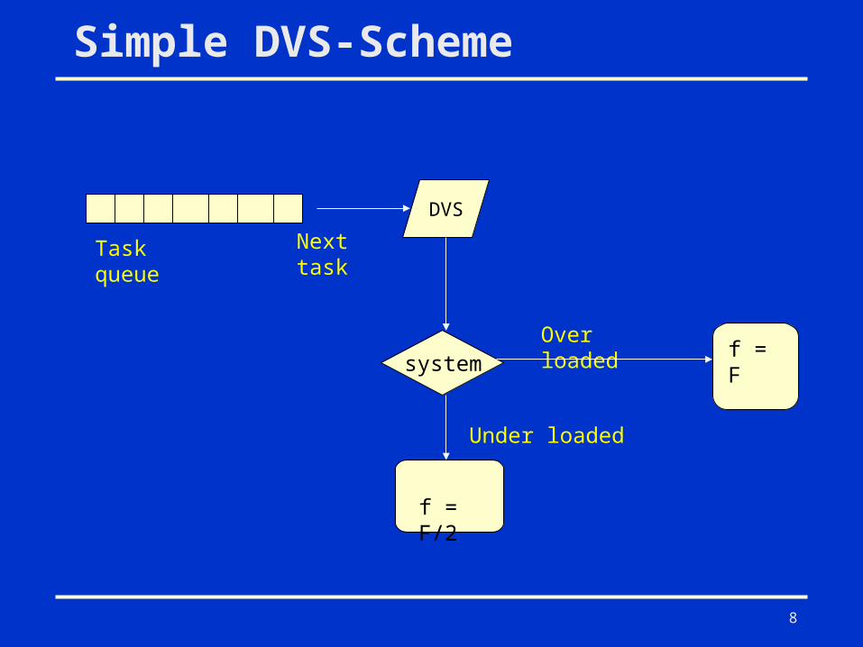
Simple DVS-Scheme
DVS
Next task
Over loaded
Under loaded
f = F/2
f = F
Task queue
system
9
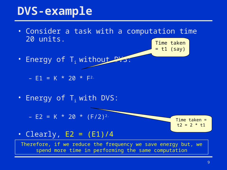
DVS-example
• Consider a task with a computation time 20 units.
• Energy of Ti without DVS:
– E1 = K * 20 * F2.
• Energy of Ti with DVS:
– E2 = K * 20 * (F/2)2.
• Clearly, E2 = (E1)/4
Time taken = t1 (say)
Time taken = t2 = 2 * t1
Therefore, if we reduce the frequency we save energy but, we spend more time in performing the same computation
10
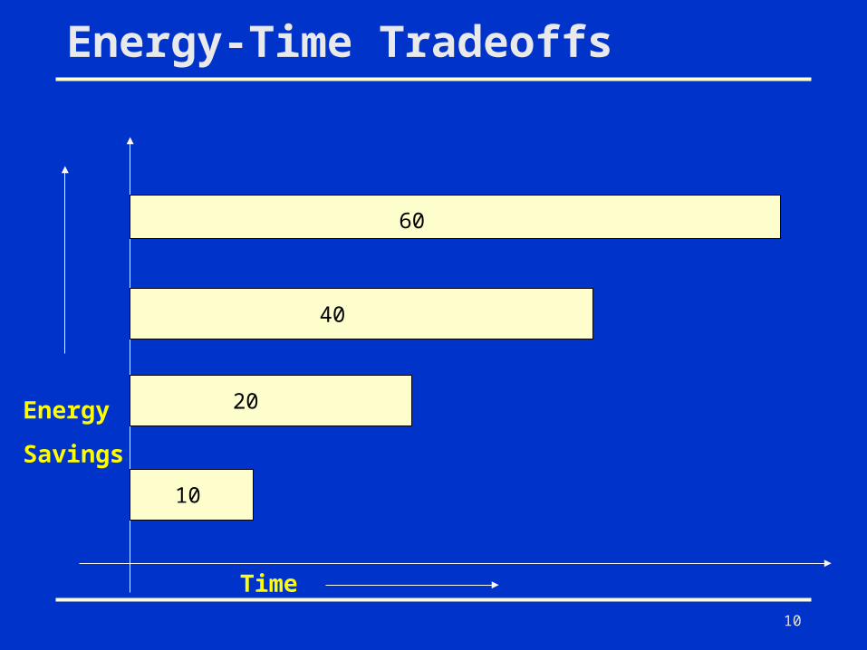
Energy-Time Tradeoffs
Time
Energy
Savings 1
0
20
40
60
11
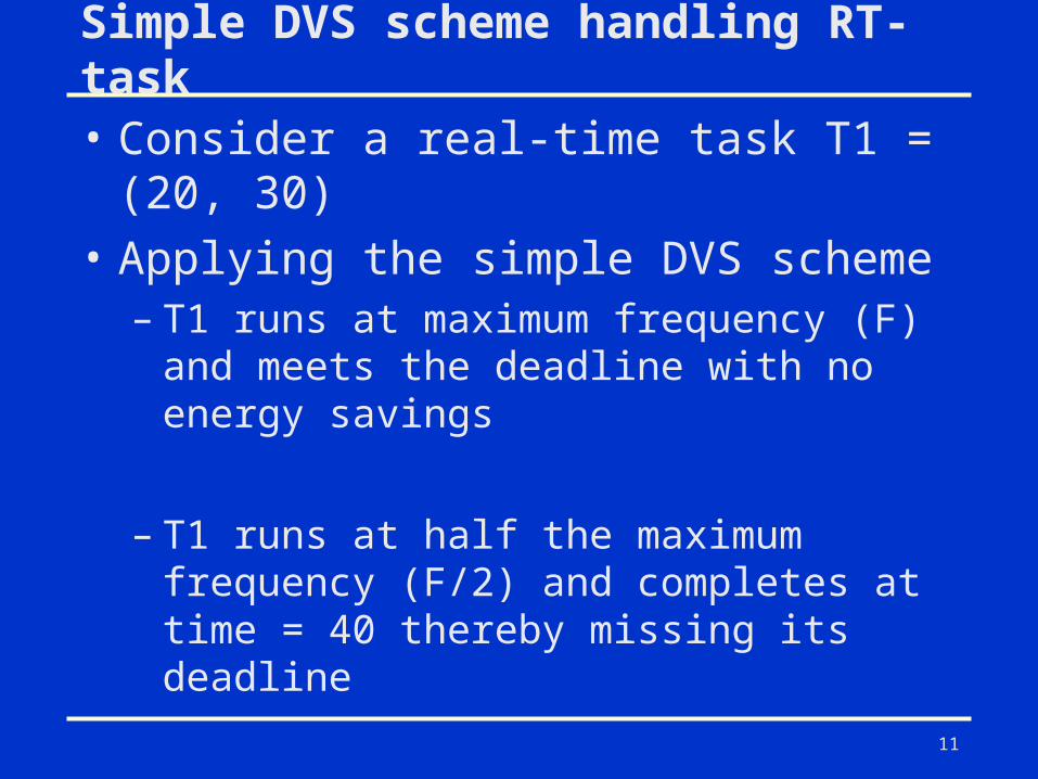
Simple DVS scheme handling RT-task
• Consider a real-time task T1 = (20, 30)
• Applying the simple DVS scheme– T1 runs at maximum frequency (F) and
meets the deadline with no energy savings
– T1 runs at half the maximum frequency (F/2) and completes at time = 40 thereby missing its deadline
12
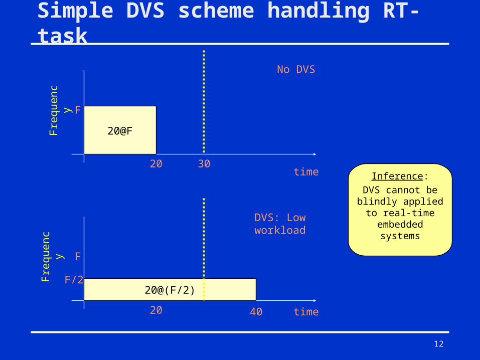
Simple DVS scheme handling RT-task
20@FFrequenc
y F
20 30time
20@(F/2)
Frequenc
y F
20
F/2
40 time
No DVS
DVS: Low workload
Inference:DVS cannot be blindly applied
to real-time embedded systems
13
Energy aware scheduling in RT Systems
Objectives Minimizing energy consumption Meeting the deadlines
14
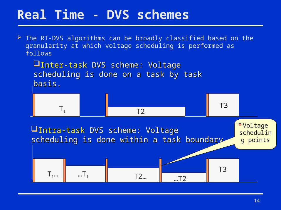
Real Time - DVS schemes
The RT-DVS algorithms can be broadly classified based on the granularity at which voltage scheduling is performed as follows
T1 T2T3
Inter-taskInter-task DVS scheme: Voltage scheduling is DVS scheme: Voltage scheduling is done on a task by task basis.done on a task by task basis.
Intra-taskIntra-task DVS scheme: Voltage scheduling is DVS scheme: Voltage scheduling is done within a task boundarydone within a task boundary
T1… T2……T1
T3…T2
Voltage scheduling points
15
Inter-task EDF
• Static voltage scaling EDF
• Cycle conserving RT-DVS
16
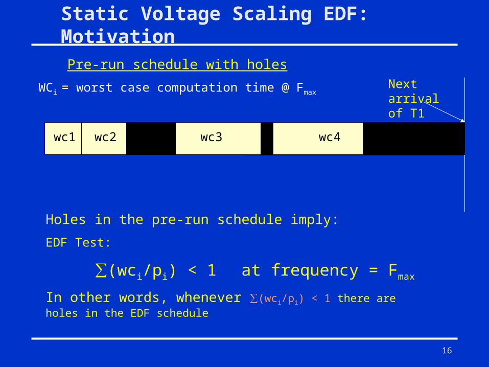
Static Voltage Scaling EDF: Motivation
wc1 wc2 wc3 wc4
Holes in the pre-run schedule imply:
EDF Test:
∑(wci/pi) < 1 at frequency = Fmax
In other words, whenever ∑(wci/pi) < 1 there are holes in the EDF schedule
Next arrival of T1
Pre-run schedule with holes
WCi = worst case computation time @ Fmax
17
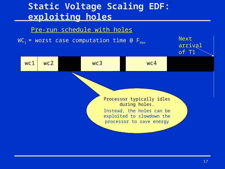
Static Voltage Scaling EDF: exploiting holes
wc1 wc2 wc3 wc4
Next arrival of T1
Pre-run schedule with holes
WCi = worst case computation time @ Fmax
Processor typically idles during holes.
Instead, the holes can be exploited to slowdown the processor to save energy
18
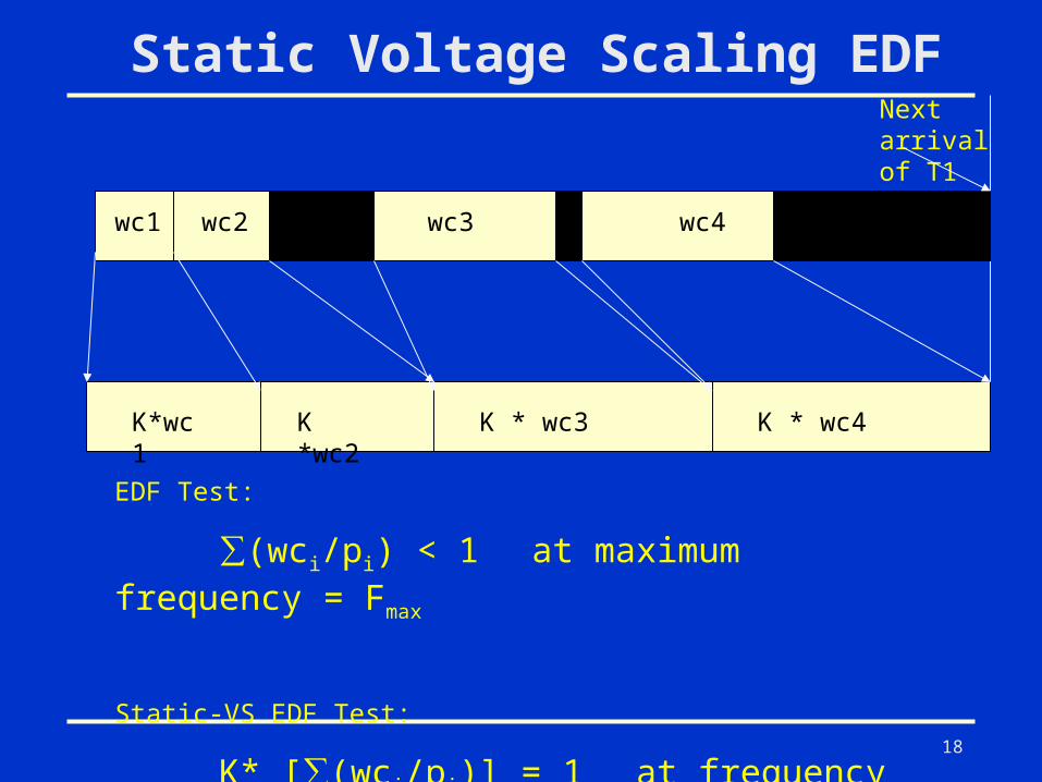
Static Voltage Scaling EDF
wc1 wc2 wc3 wc4
K*wc1 K *wc2 K * wc3 K * wc4
EDF Test:
∑(wci/pi) < 1 at maximum frequency = Fmax
Static-VS EDF Test:
K* [∑(wci/pi)] = 1 at frequency = Fmax/K
Next arrival of T1
19
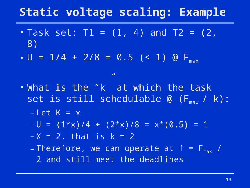
Static voltage scaling: Example
• Task set: T1 = (1, 4) and T2 = (2, 8)
• U = 1/4 + 2/8 = 0.5 (< 1) @ Fmax
• What is the “k” at which the task set is still schedulable @ (Fmax / k):
– Let K = x– U = (1*x)/4 + (2*x)/8 = x*(0.5) = 1– X = 2, that is k = 2
– Therefore, we can operate at f = Fmax / 2 and still meet the deadlines
20
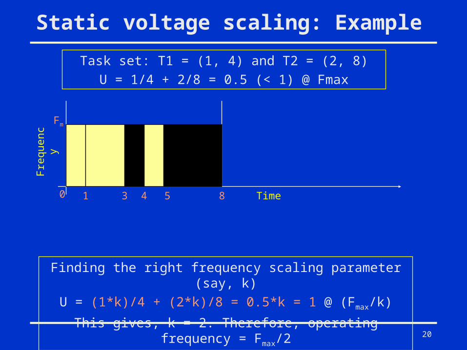
Static voltage scaling: Example
Task set: T1 = (1, 4) and T2 = (2, 8)U = 1/4 + 2/8 = 0.5 (< 1) @ Fmax
0 1 3 4 5 8
Frequenc
y
Fm
Time
Finding the right frequency scaling parameter (say, k)U = (1*k)/4 + (2*k)/8 = 0.5*k = 1 @ (Fmax/k)
This gives, k = 2. Therefore, operating frequency = Fmax/2
21
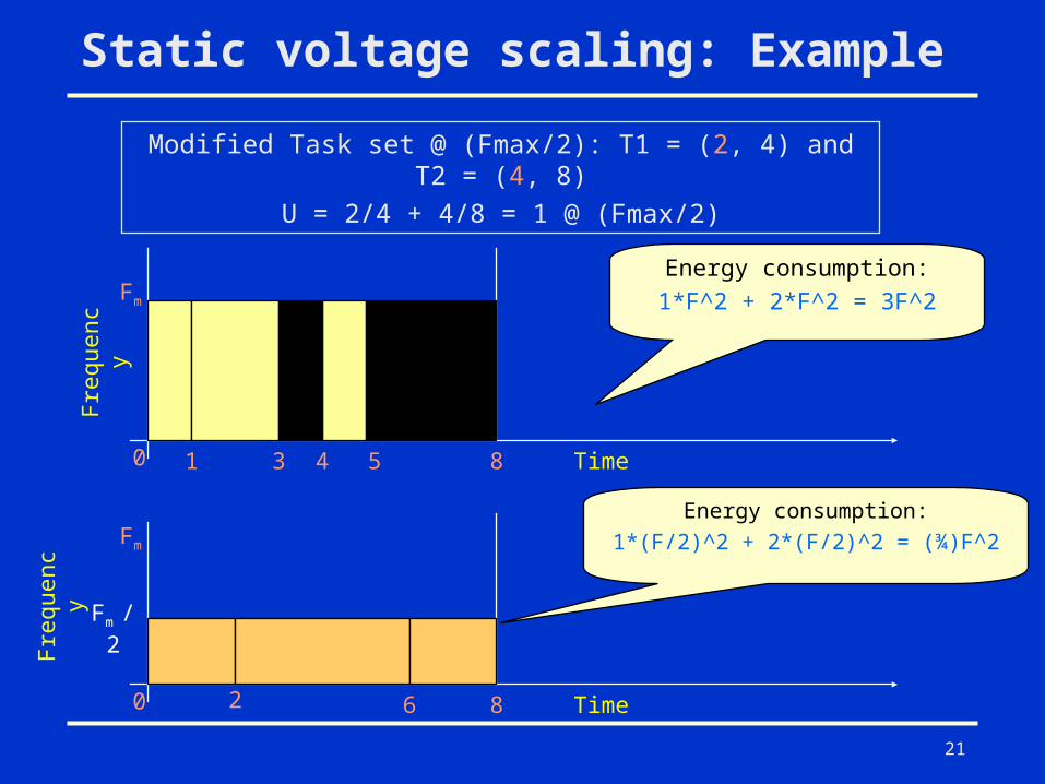
Static voltage scaling: Example
Modified Task set @ (Fmax/2): T1 = (2, 4) and T2 = (4, 8)
U = 2/4 + 4/8 = 1 @ (Fmax/2)
0 1 3 4 5 8
Frequenc
y
Fm
Time
0 2 6 8
Frequenc
y
Fm
Time
Fm / 2
Energy consumption:1*F^2 + 2*F^2 = 3F^2
Energy consumption:1*(F/2)^2 + 2*(F/2)^2 = (¾)F^2
22
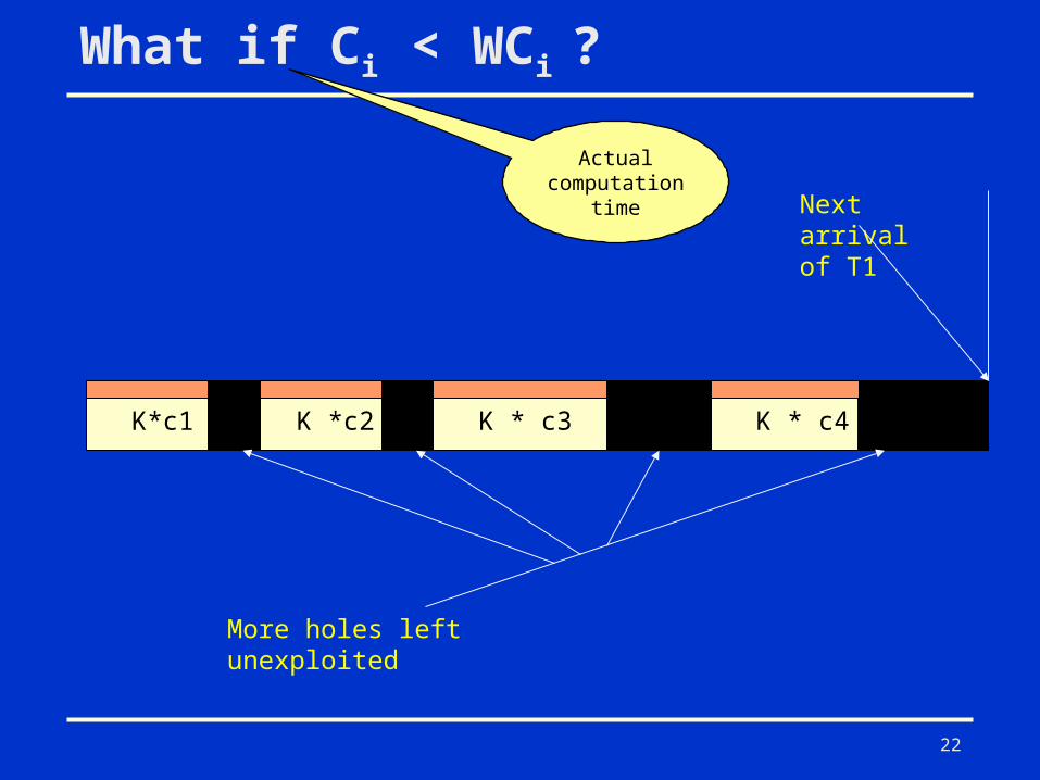
What if Ci < WCi ?
K*c1 K *c2 K * c3 K * c4
Next arrival of T1
More holes left unexploited
Actual computation
time
23
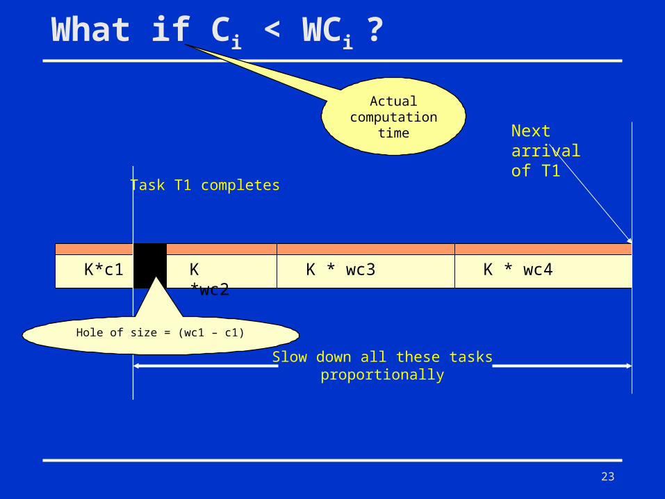
What if Ci < WCi ?
K*c1 K *wc2 K * wc3 K * wc4
Next arrival of T1
Actual computation
time
Task T1 completes
Slow down all these tasks proportionally
Hole of size = (wc1 – c1)
24
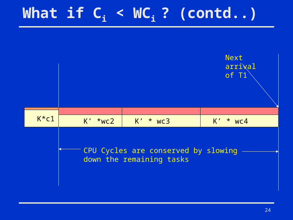
What if Ci < WCi ? (contd..)
K*c1 K’ *wc2 K’ * wc3 K’ * wc4
Next arrival of T1
CPU Cycles are conserved by slowing down the remaining tasks
25
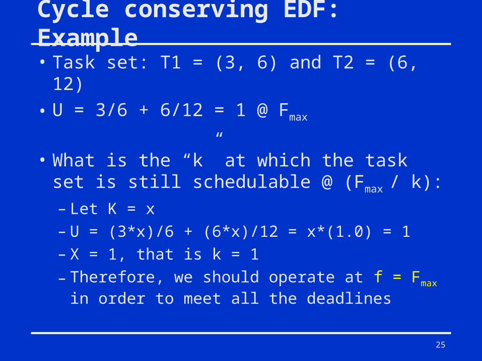
Cycle conserving EDF: Example
• Task set: T1 = (3, 6) and T2 = (6, 12)
• U = 3/6 + 6/12 = 1 @ Fmax
• What is the “k” at which the task set is still schedulable @ (Fmax / k):
– Let K = x– U = (3*x)/6 + (6*x)/12 = x*(1.0) = 1– X = 1, that is k = 1
– Therefore, we should operate at f = Fmax in order to meet all the deadlines
26
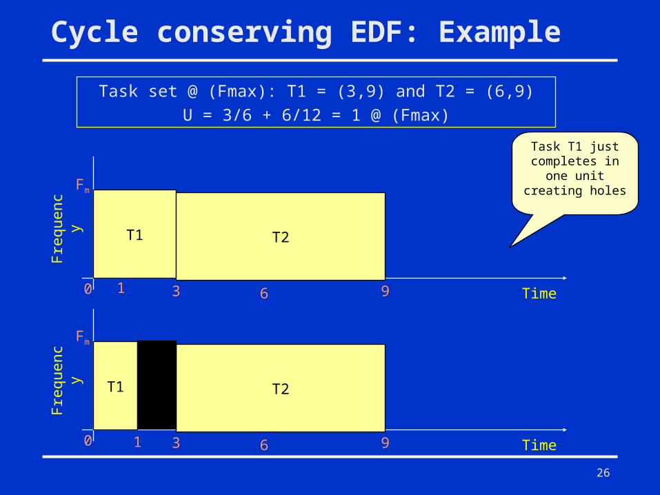
Cycle conserving EDF: Example
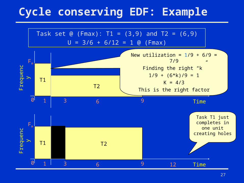
Task set @ (Fmax): T1 = (3,9) and T2 = (6,9)U = 3/6 + 6/12 = 1 @ (Fmax)
T1
0 1 3 6 9
Frequenc
y
Fm
Time
T2
T1
0 1 3 6 9
Frequenc
y
Fm
Time
T2
Task T1 just completes in
one unit creating holes
27
Cycle conserving EDF: Example
Task set @ (Fmax): T1 = (3,9) and T2 = (6,9)U = 3/6 + 6/12 = 1 @ (Fmax)
T1
0 1 3 6 9
Frequenc
y
Fm
Time
T2
New utilization = 1/9 + 6/9 = 7/9Finding the right “k”
1/9 + (6*k)/9 = 1K = 4/3
This is the right factor
T1
0 1 3 6 9
Frequenc
y
Fm
Time
T2
12
Task T1 just completes in
one unit creating holes
28
Intra Task Energy Management
• Intra-task DVS: adjusts the voltage and clock speed within a task.
• Identifies the slack time generated within a task due to workload variation.
• Application code is preprocessed to enable the run-time clock/voltage adjustment.
29
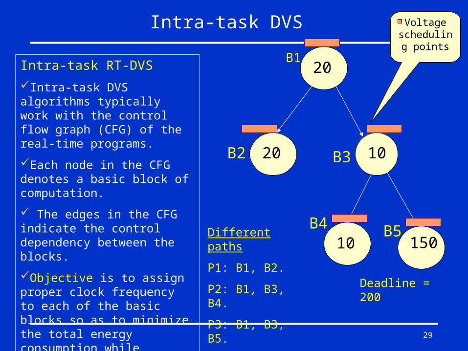
Different paths
P1: B1, B2.
P2: B1, B3, B4.
P3: B1, B3, B5.
B2
Intra-task DVS
20
20 10
10 150
B1
B3
B4 B5
Deadline = 200
Voltage scheduling points
Intra-task RT-DVS
Intra-task DVS algorithms typically work with the control flow graph (CFG) of the real-time programs.
Each node in the CFG denotes a basic block of computation.
The edges in the CFG indicate the control dependency between the blocks.
Objective is to assign proper clock frequency to each of the basic blocks so as to minimize the total energy consumption while meeting the task deadline.
30
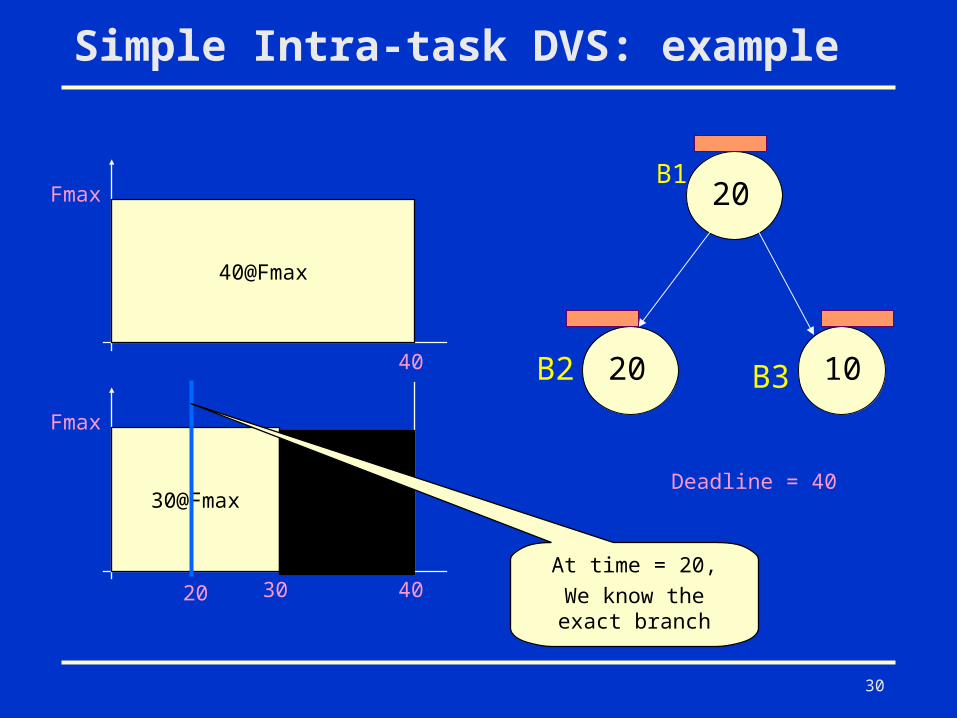
Simple Intra-task DVS: example
B2
20
20 10
B1
B3
Deadline = 40
40@Fmax
Fmax
40
30@Fmax
Fmax
4020At time = 20,
We know the exact branch
30
31
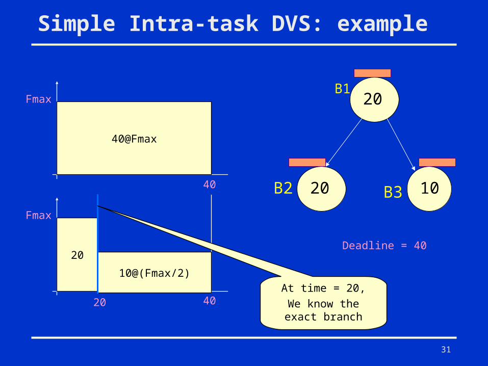
Simple Intra-task DVS: example
B2
20
20 10
B1
B3
Deadline = 40
40@Fmax
Fmax
40
20
Fmax
40
10@(Fmax/2)
20At time = 20,
We know the exact branch
32
Summary
• DVS schemes can significantly reduce energy in embedded systems.