Embed Size (px)
Citation preview

1
ECE 480
Wireless Systems
Lecture 4
Propagation and Modulation of RF Waves
2
Antenna Radiation Characteristics
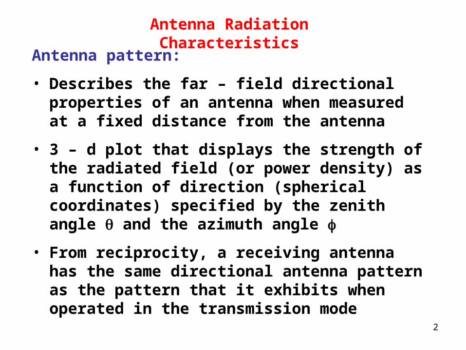
Antenna pattern:
• Describes the far – field directional properties of an antenna when measured at a fixed distance from the antenna
• 3 – d plot that displays the strength of the radiated field (or power density) as a function of direction (spherical coordinates) specified by the zenith angle and the azimuth angle
• From reciprocity, a receiving antenna has the same directional antenna pattern as the pattern that it exhibits when operated in the transmission mode

3
The differential power through an elemental area dA is
rad av avˆd P S d A S R dA S dA
always in the radial direction in the far – field region
avS

4
radd P S dA
d A R sin d d 2
Define: Solid angle,
d Ad sin d d steradians
R
2
4 for a spherical surface

5
radd P S dAd A
dR
2
d A R d 2
radd P R S R , , d 2
The total power radiated by an antenna is given by
radP R S R , , sin d d
2
2
0 0

6
rad maxP R S F , sin d d
2
2
0 0
rad maxP R S F , d 2
4
F , is the normalized radiation intensity
F , 1

73 – D Pattern of a Narrow – Beam Antenna

8
Antenna Pattern
It is convenient to characterize the variation of F ( , ) in two dimensions
Elevation Plane ( - plane)
Corresponds to a single value of ( = 0 x –z plane) ( = 90 y –z plane)
Azimuth Plane ( - plane)
Corresponds to = 90 o (x – y plane)
Two principle planes of the spherical coordinate system

9
Clearer to express F in db for highly directive patterns
F dB log F10
= 0 plane

10
Side lobes are undesirable
• Wasted energy
• Possible interference
11
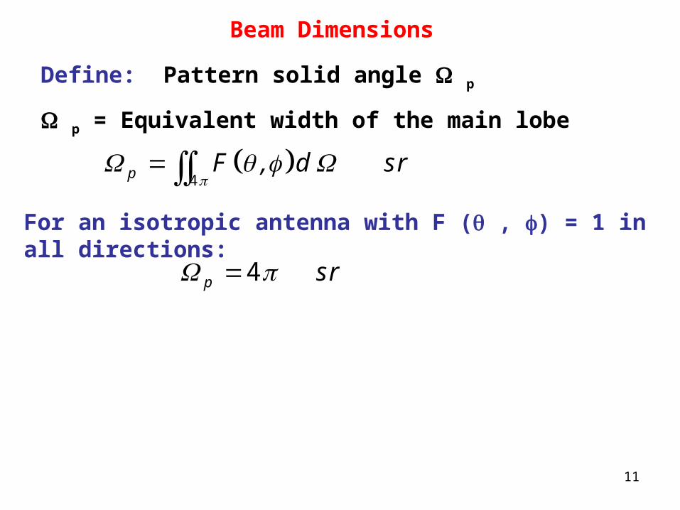
Beam Dimensions
Define: Pattern solid angle p
p = Equivalent width of the main lobe
p F , d sr
4For an isotropic antenna with F ( , ) = 1 in all directions:
p sr 4

12
Defines an equivalent cone over which all the radiation of the actual antenna is concentrated with equal intensity signal equal to the maximum of the actual pattern

13
The half – power (3 dB) beamwidth, , is defined as the angular width of the main lobe between the two angles at which the magnitude of F ( , ) is equal to half its peak value
2 1

14
F () is max at = 90 o , 2 = 135 0 , 1 = 45 o , = 135 o – 45 o = 90 o

15
Null Beamwidth, null
Beamwidth between the first nulls on either side of the peak

16
Antenna Directivity
max
av av
p
FD
F F F , d
4
1 114
4
p = Pattern solid angle
For an isotropic antenna, p = 4
D = 1

17
D can also be expressed as
max max
rad av
rad
R S SD
P S
P
R
2
2
4
4
av isoS SS iso = power density radiated by an isotropic antenna
D = ratio of the maximum power density radiated by the antenna to the power density radiated by an isotropic antenna

18
For an antenna with a single main lobe pointing in the z direction:
p xz yz
p xz yz
D
4 4

19
Example – Antenna Radiation Properties
Determine:
a. The direction of maximum radiation
b. Pattern solid angle
c. directivity
d. half – power beamwidth
in the y-z plane for an antenna that radiates into only the upper hemisphere and its normalized radiation intensity is given by
F , cos 2

20
Solution
F , cos 2The statement in the upper hemisphere
can be written mathematically as
F , F cos
elsewhere
2 02
0 2
0

21
a. The function
F cos 2
is maximum when = 0
Polar plot of
F cos 2
b. The pattern solid angle is given by
p F , d
cos sin d d
cosd d sr
4
2 22
0 0
2 23 2
0 00
1 2
3 3 3

22
F cos 2
Polar plot of
c.
p
D
D d B log . d B
4 34 6
2
10 6 7 78
d. The half – power by setting
F cos . 2 0 5
o o
o
1 2
2 1
45 45
90

23
Example – Directivity of a Hertzian Dipole
D
F , sin d d
.
sin d d
4
23
0 0
4
4 41 5
83
For a Hertzian dipole:
F , sin 2

24
Antenna Gain
Define: Radiation Efficiency,
P t = Transmitter power sent to the antenna
P rad = Power radiated into space
P loss = Power loss due to heat in the antenna
= P t – P rad
rad
t
P
P
= 1 for a lossless antenna

25
Define: Antenna Gain, G
max
t
R SG
P
24
max
rad
R SD
P
24
G D
Accounts for the losses in the antenna

26
Radiation Resistance
P loss = Power loss due to heat in the antenna = P t – P rad
I
I
I
t ant loss rad
loss loss
rad rad
P R P P
P R
P R
20
20
20
1
21
21
2
rad rad rad
t rad loss rad loss
P P R
P P P R R

27
To find the radiation resistance:
• Find the far – field power by integrating the far – field power density over a sphere
• Equate to
Irad radP R 20
1
2

28
Example – Radiation Resistance and Efficiency of a Hertzian Dipole
A 4 – cm long center – fed dipole is used as an antenna at 75 MHz. The antenna wire is made of copper and has a radius a = 0.4 mm. The loss resistance of a circular wire is given by
closs
c
fR
a
2
l
Calculate the radiation resistance and the radiation efficiency of the dipole antenna

29
Solution
The parameters of copper are
r
c
S.
m
7
1
5 8 10
closs
c
fR
a
.
. .
.
6 7
7
2
0 04 75 10 4 10
2 0 004 5 8 10
0 036
l

30
At 75 MHz:
cm
f
cm.
m
8
6
3 104
75 10
40 01
4
l
This is a short dipole
From before,
maxSR
220
2
15 lI
rad max
RP S
D
24

31
I
I
rad
RP
D R
2220
2
22 2
0
154
40
l
l
I Irad radP R
22 2 20 0
140
2
l
rad
.R
.
2 22 3 0 04
80 804
0 08
l
rad
rad loss
R .. %
R R . .
0 08
0 69 690 08 0 036

32
Half – Wave Dipole Antenna
j ti t cos t cos k z Re cos k z e 0 0I I
z cos k z z
0 4 4I I
In phasor form:
k
2

33
For a short dipole
j k Rk eE sin
R
EH
0 0
0
4
lj I
Expand these expressions to obtain similar expressions for the half – wave dipole

34
j k s
s
j k ed E z z dz sin
s
d E zd H z
0
0
4
I
Consider an infinitesimal dipole segment of length dz excited by a current and located a distance from the observation point
zI

35
The far field due to radiation by the entire antenna is given by
z
E d E
4
4
Two assumptions:
s
s R
1 1
(length factor)

36
j k s
s
j k ed E z z d z sin
s
0
4I
Note that "s" appears in the equation twice – once for the distance away and once for the phase factor
s R is not valid for the length factor
If Q is located at the top of the dipole, the phase
factor is which is not acceptable 2
s R z cos

37
j k R
j k z cosj k ed E z z d z sin e
R
0
4I
j k Rcos cose
E j Isin R
EH
0
0
260
cos cosE
S R ,sin
22
20
22

38
cos cosE
S R , Ssin
22
0 20
22
cos cosE
S R ,R sin
2220
2 20
15 22
I

39
S R , is max when 2
maxS SR
20
0 2
15 I
cos cosS R ,
FS sin
2
0
2

40
Directivity of Half – Wave Dipole
Need P rad and S (R , )
radP R S R , d
cos cossin d d
sin
.
2
4
2
2 2 20
0 0
20
15 2
36 6
I
I
maxSR
20
2
15 I
max
rad
R S RD . . d B
P . R
2 220
2 20
4 1541 64 2 15
36 6
I
I

41
Radiation Resistance of Half – Wave Dipole
radrad
P .R
20
2 20 0
2 2 36 673
I
I I
Recall: for the short dipole (l = 4 cm) at 75 MHz
R rad = 0.08
R loss = 0.036
rad
rad loss
R .%
R R . .
0 08
690 08 0 036
For the half – wave dipole (l = 4 m) at 75 MHz
R loss = 1.8
rad
rad loss
R%
R R .
73
9873 1 8

42
Effective Area of a Receiving Antenna
Assume an incident wave with a power density of S i
The effective area of the antenna, A e , is
inte
i
PA
S
P int = Power intercepted by the antenna
It can be shown:
oc
int Lrad
VP P
R
2
8
ocV = Magnitude of the open – circuit voltage developed across the antenna

43
The power density carried by the wave is
i i
i
ocinte
irad i
E ES
VPA
S R E
2 2
0
2
2
2 240
30
For the short dipole
rad oc iR V E
2280
ll
eA
23
8

44
In terms of D:
e
DA m
2
2
4
Valid for any antenna
Example: Antenna Area
The effective area of an antenna is 9 m 2. What is its directivity in db at 3 GHz?
c.
f
8
9
3 100 1
3 10
eAD . . d B
.
422
4 4 91 13 10 40 53
0 1

45
Friis Transmission Formula
Assumptions:
• Each antenna is in the far – field region of the other
• Peak of the radiation pattern of each antenna is aligned with the other
• Transmission is lossless

46
tiso
PS
R
24For an isotropic antenna: (ideal)
In the practical case, t t tr t iso t t iso
D PS G S D S
R
24
In terms of the effective area A t of the transmitting antenna
t t tr
A PS
R
2 2

47
On the receiving side,t t r t
int r r
A A PP S A
R
2 2
rec r intP P
rec t r t rt r
t
P A AG G
P R R
2
2 2 4
Friis transmission formula

48
rec t r t rt r t t t r r r
t
P A AG G F , F ,
P R R
2
2 2 4
When the antennas are not aligned
(More general expression)

49
Homework
1. Determine the following:
a. The direction of maximum radiation
b. Directivity
c. Beam solid angle
d. Half – power beamwidth in the x – z plane
for an antenna whose normalized radiation intensity is given by:
oF , for ,
elsewhere
1 0 60 0 2
0
Hint: Sketch the pattern first
50
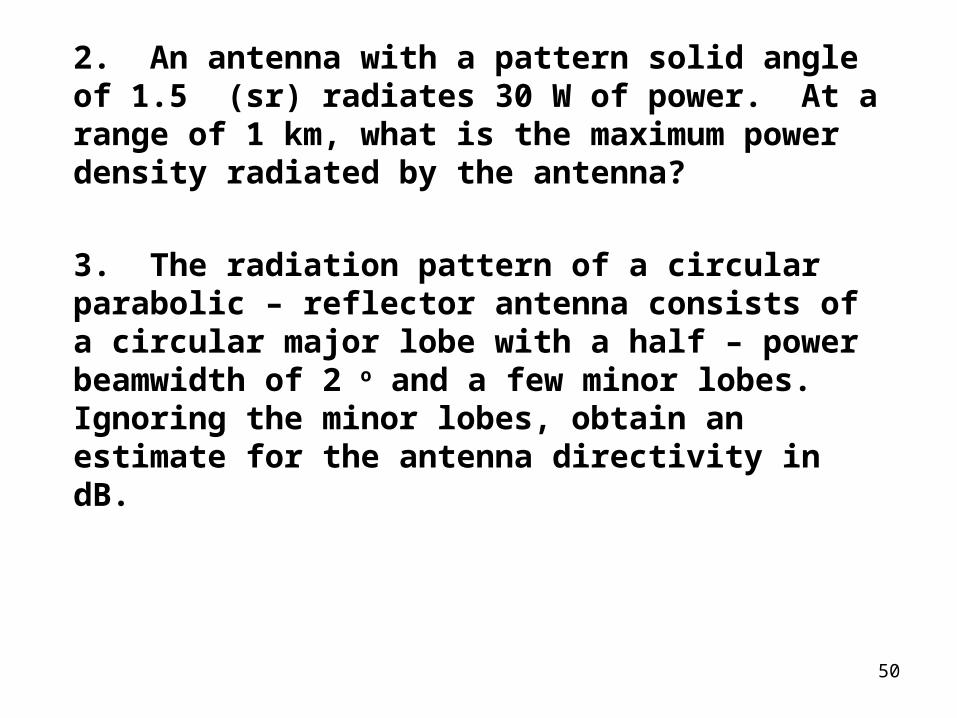
2. An antenna with a pattern solid angle of 1.5 (sr) radiates 30 W of power. At a range of 1 km, what is the maximum power density radiated by the antenna?
3. The radiation pattern of a circular parabolic – reflector antenna consists of a circular major lobe with a half – power beamwidth of 2 o and a few minor lobes. Ignoring the minor lobes, obtain an estimate for the antenna directivity in dB.

51
Analog Modulation
Several basic types
• Amplitude modulation (AM)
• Frequency modulation (FM)
• Pulse code modulation (PCM)
• Pulse width modulation (PWM)
• High frequencies require smaller antennas
• Modulation impresses a lower frequency onto a higher frequency for easier transmission
• The signal is modulated at the transmission end and demodulated at the receiving end

52
Amplitude Modulation
Carrier wave – High frequency signal that transports the intelligence
Signal wave – Low frequency signal that contains the intelligence

53
AM transmitter
• DC shifts the modulating signal
• Multiplies it with the carrier wave using a frequency mixer
• Mixer must be nonlinear
• Output is a signal with the same frequency as the carrier with peaks and valleys that vary in proportion to the strength of the modulating signal
• Signal is amplified and sent to the antenna

54
The mixer is usually a "square law" device, such as a diode or B – E junction of a transistor
Output input 2
Suppose that we apply the following signals to a square law device
f t A cos t
f t A cos t
1 1 1
2 2 2
The output will be
o of t A A cos t A cos t 2
1 1 2 2

55
Homework
o of t A A cos t A cos t 2
1 1 2 2
Determine all possible output frequencies

56
Advantages
• Simplicity
• Cost
Disadvantages
• Susceptible to atmospheric interference (static)
• Narrow bandwidth (550 – 1500 KHz)

57
AM Receiver
• Tunable filter
• Envelope detector (diode)
• Capacitor is used to eliminate the carrier and to undo the DC shift
• Will generally include some form of automatic gain control (AGC)

58
Forms of Amplitude Modulation
In the most basic form, an AM signal in the frequency domain consists of
• The carrier signal
• Information at f c + f m (upper sideband)
• Information at f c - f m (lower sideband)
(US and LS are mirror images)
This wastes transmission power
• Carrier contains no information
• Information is all contained in only one of the sidebands

59
Frequently, in communications systems, the carrier and/or one of the sidebands is suppressed or reduced
• If only the carrier is reduced or suppressed, the process is called "Double – Sideband Suppressed (Reduced) Carrier" (DSSC or DSRC)
• If the carrier and one of the sidebands is suppressed or reduced, the process is called "Single – Sideband Suppressed (Reduced) Carrier" (SSSC or SSRC)
• Often, the carrier and one of the sidebands is totally suppressed. This process is simply called "Single Sideband"
• The carrier must be regenerated at the receiver end

60
Example
Consider a carrier with a frequency c
cc t C sin t
Suppose we want to modulate the carrier with a signal
mm t M sin t
The signal is amplitude – modulated by adding m(t) to C
The expression for this signal is
m cy t C M sin t sin t
Expanding this expression
m c m c
c
cos t cos ty t C sin t M M
2 2

61
Convert to frequency domain by taking the Fourier Transform
cy t C m t cos t
c cj t j te e
y t C m t 2
Take Fourier Transform
c c c cY C M C M 1 1
2 2
x = Unit impulse function

62
Eff = 33 % Eff = 100 %Eff = 100 %

63
Modulation Index
peak value of m th
C
Measure of the modulating signal wrt the carrier signal

64

65