Embed Size (px)
Citation preview
1
ECE 102Engineering Computation
Chapter 20Source Transformations
Dr. Herbert G. Mayer, PSUDr. Herbert G. Mayer, PSUStatus 9/2/2015Status 9/2/2015
For use at CCUT Fall 2015For use at CCUT Fall 2015
2
Syllabus
GoalGoal CVS With RCVS With Rpp Removed Removed CCS With RCCS With Rss Removed Removed CVS to CCS TransformationCVS to CCS Transformation Detailed SampleDetailed Sample ConclusionConclusion ExercisesExercises
3
Goal The Node-Voltage and Mesh-Current Methods are
powerful tools to compute circuit parameters Cramer’s Rule is especially useful for a
large number of unknowns Sometimes a circuit can be transformed into
another one that is simpler, yet electrically equivalent
Generally that will simplify computations We’ll learn a few source transformations here Method 1: remove parallel load from CVS Method 2: remove serial load from CCS Method 3: Transform CVS <-> CCS bilaterally
4
CVS With Rp Removed
5
CVS With Rp Removed
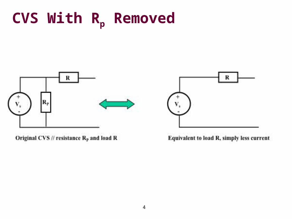
Removing the load Rp parallel to the CVS has no impact on externally connected loads RL
Such loads RL—not drawn here— will be in series with resistor R
Removal of Rp decreases the amount of current that the CVS has to produce, to deliver equal voltage to both Rp and the series of R and load RL
This simplification is one of several source transformations an engineer should look for, before computing unknowns in a circuit
6
CCS With Rs Removed
7
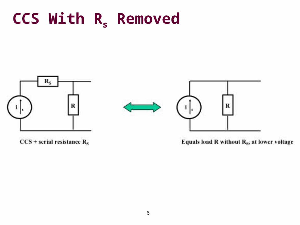
CCS With Rs Removed
Removing the load Rs in series with the CCS has no impact on external loads RL
Such a load RL—not drawn here— will be parallel to resistor R
Removal of Rs will certainly decrease the amount of voltage the CCS has to produce, to deliver equal current to both Rs in series with R parallel to RL
Such a removal is one of several source transformations to simplify computing unknown units in a circuit
8
CVS to CCS Bilateral Transformation
9
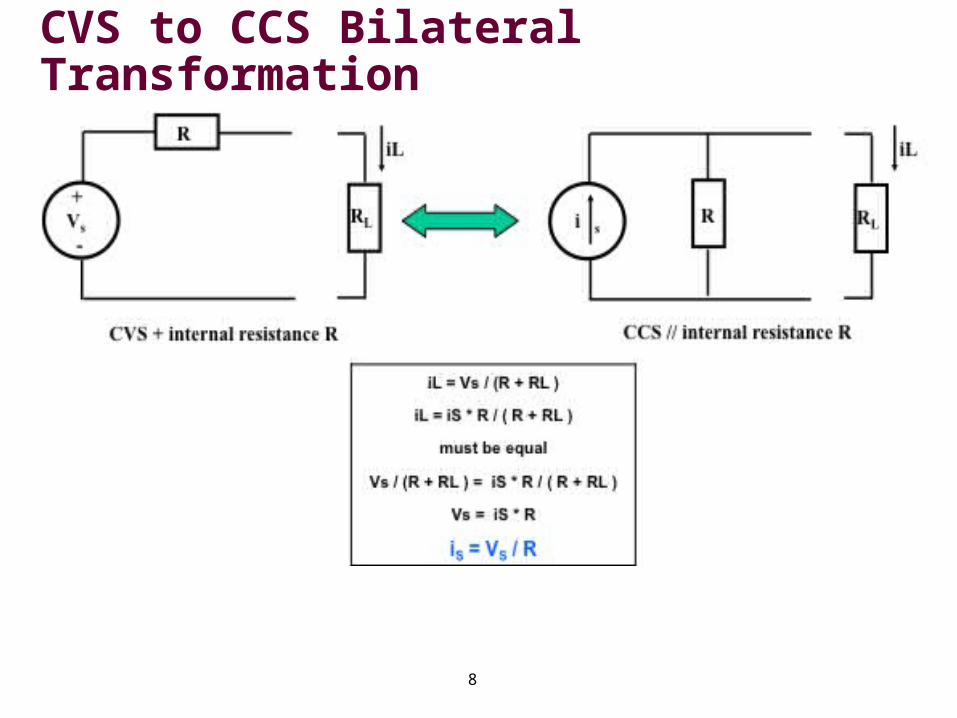
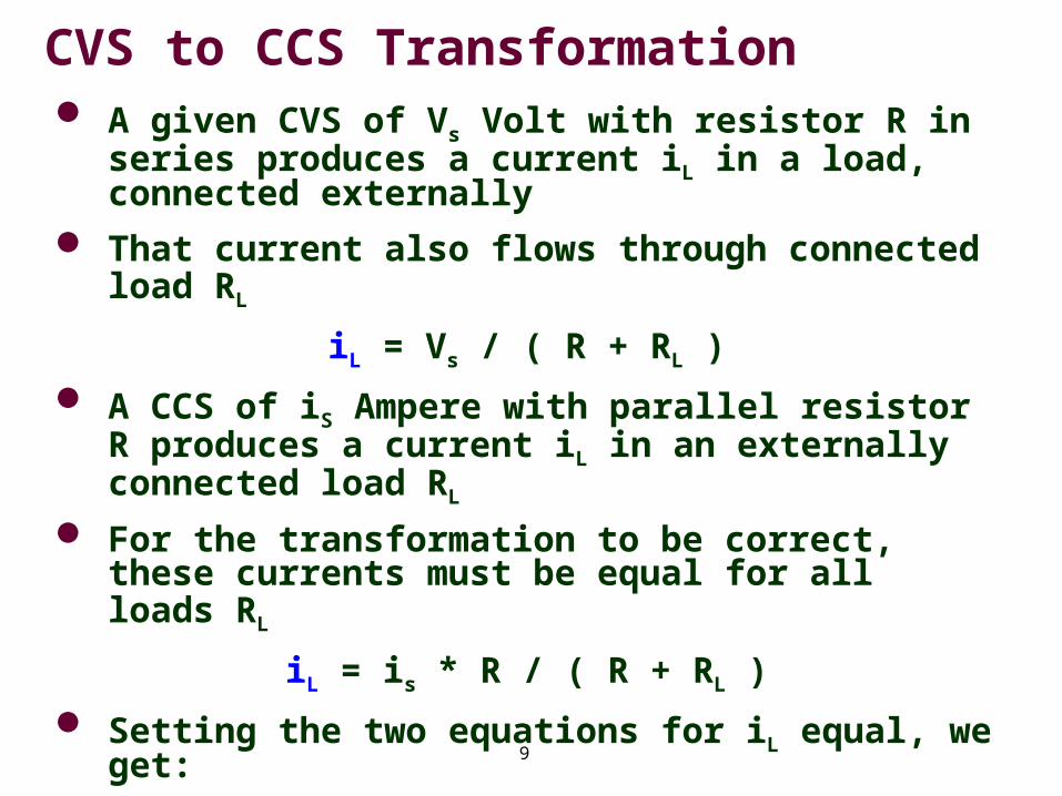
CVS to CCS Transformation A given CVS of Vs Volt with resistor R in
series produces a current iL in a load, connected externally
That current also flows through connected load RL
iL = Vs / ( R + RL )
A CCS of iS Ampere with parallel resistor R produces a current iL in an externally connected load RL
For the transformation to be correct, these currents must be equal for all loads RL
iL = is * R / ( R + RL )
Setting the two equations for iL equal, we get:
is = Vs / R
Vs = is * R
10
Detailed Sample
We’ll use these simplifications in the next example to generate an equivalent circuit that is minimal
I.e. eliminate all redundancies from right to left
This example is taken from [1], page 110-111, expanded for added detail
First we analyze the sample, identifying all
# of Essential nodes ____
# of Essential branches ____ Then we compute the power consumed or
produced in the 6V CVS
11
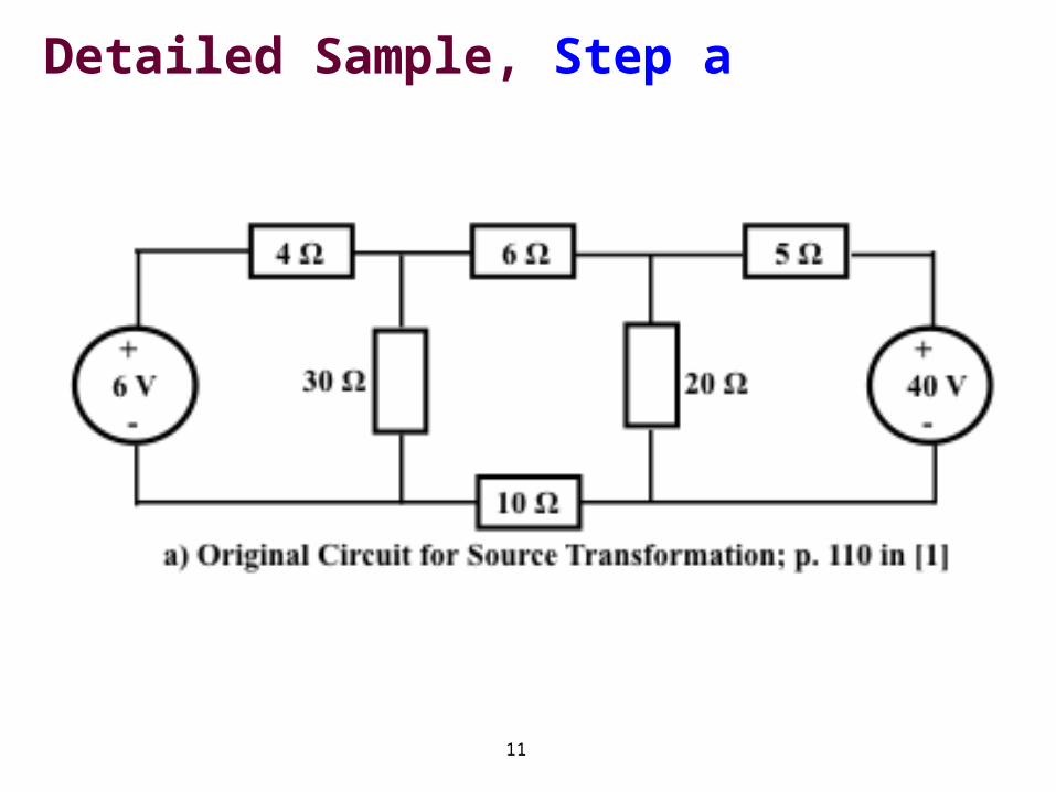
Detailed Sample, Step a
12
Detailed Sample
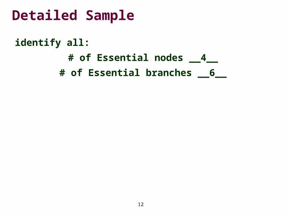
identify all:
# of Essential nodes __4__
# of Essential branches __6__
13
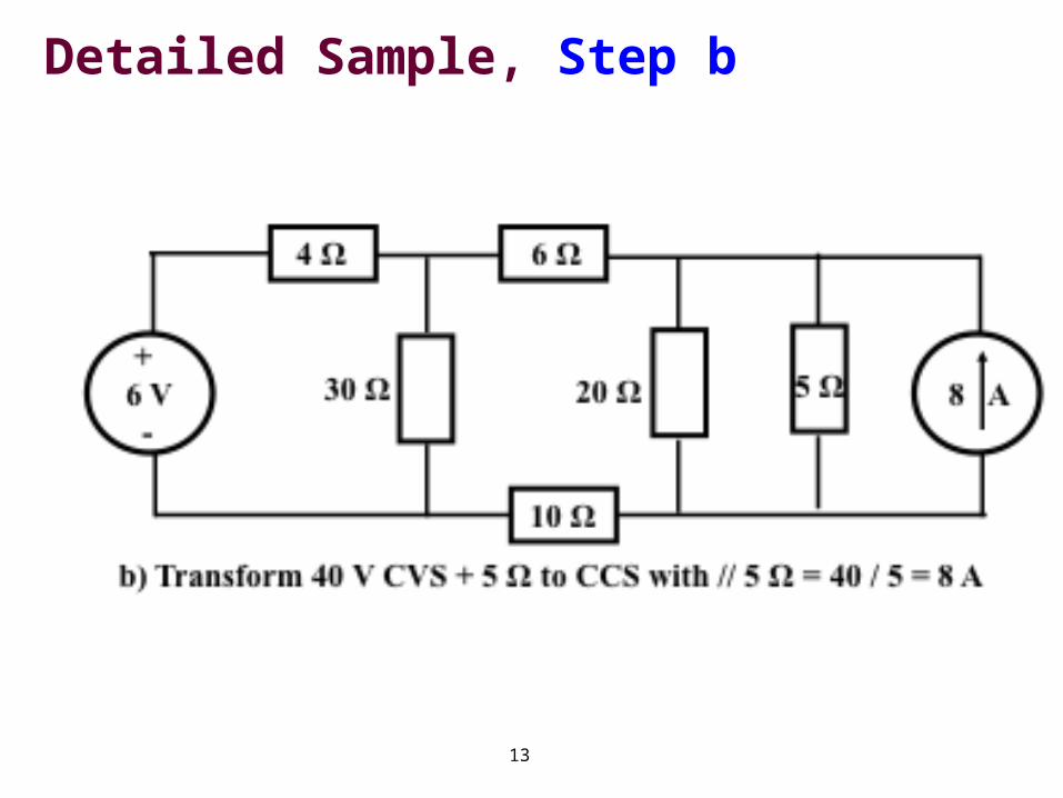
,Detailed Sample, Step b
14
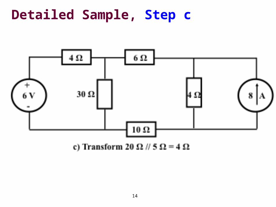
,Detailed Sample, Step c
15
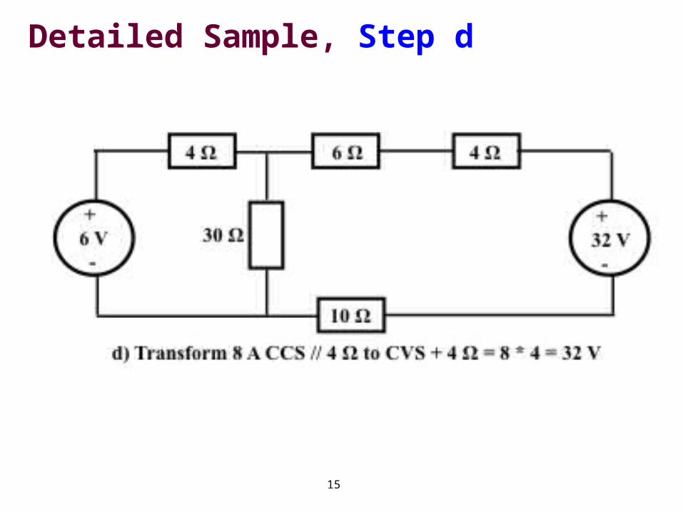
,Detailed Sample, Step d
16
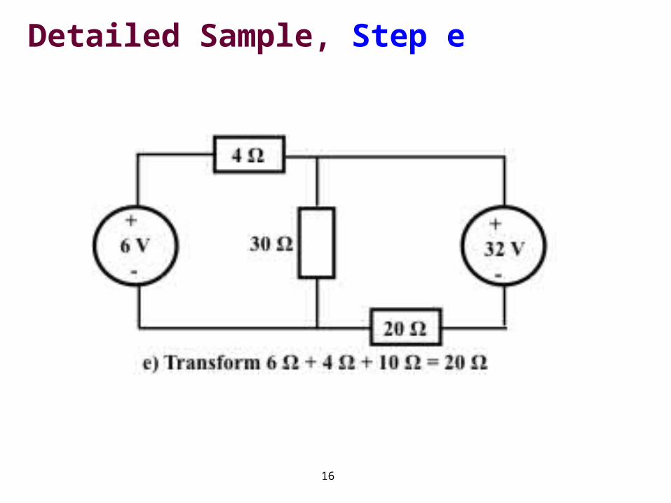
,Detailed Sample, Step e
17
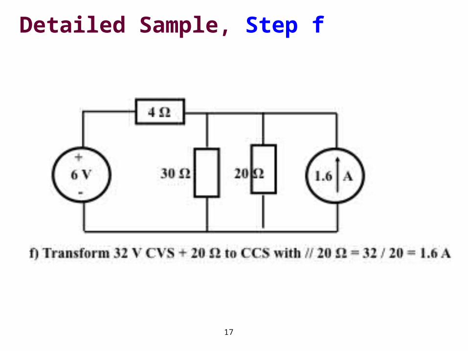
,Detailed Sample, Step f
18
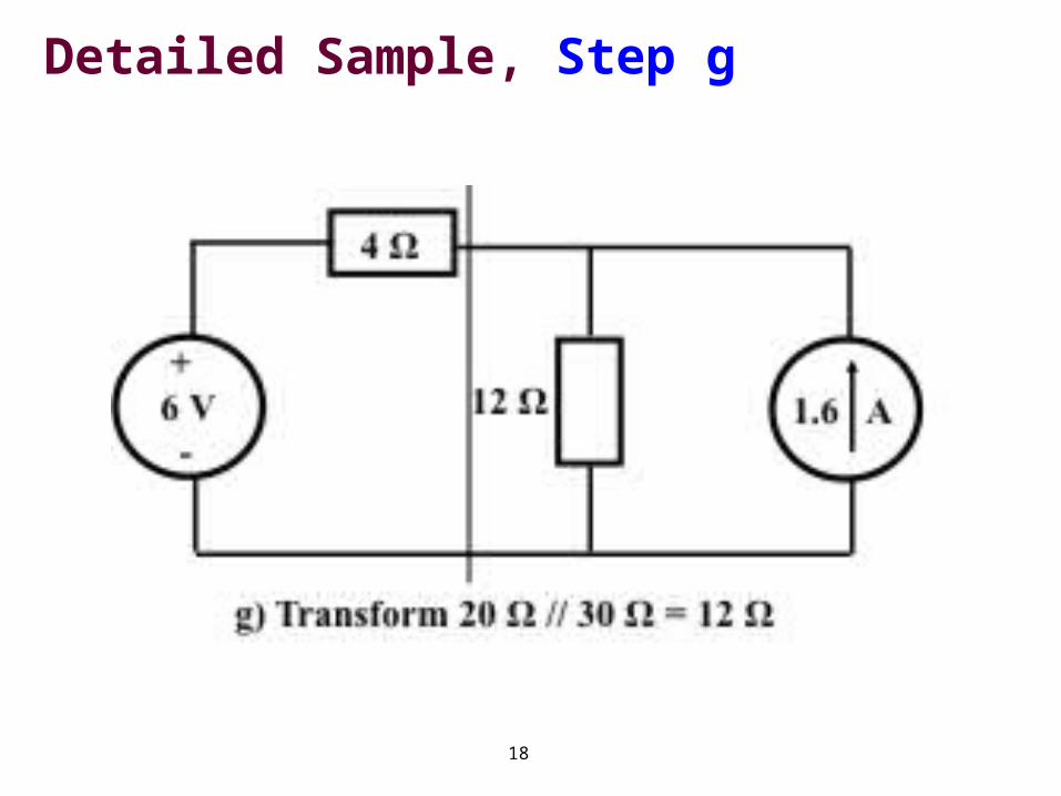
,Detailed Sample, Step g
19
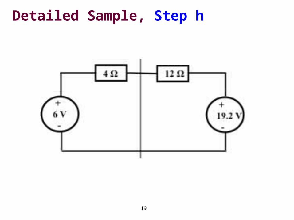
,Detailed Sample, Step h

20
Power in 6 V CVS The current through network h, in the
direction of the 6 V CVS source is:
i = ( 19.2 - 6 ) / ( 4 + 12 ) [ V / Ω ]
i = 0.825 [ A ] Power in the 6 V CVS, being current *
voltage is:
P = P6V = i * V = 0.825 * 6
P6V = 4.95 W
That power is absorbed in the 6 V source, it is not being delivered by the 6 V source! It is delivered by the higher voltage CVS of 19.2 V
21
Conclusion
Such source transformations are not always possible
Exploiting them requires that there be a certain degree of redundancy
Frequently that is the case, and then we can simplify
Engineers must check carefully, how much simplification is feasible, and then simplify
But no more
22
Exercise 1
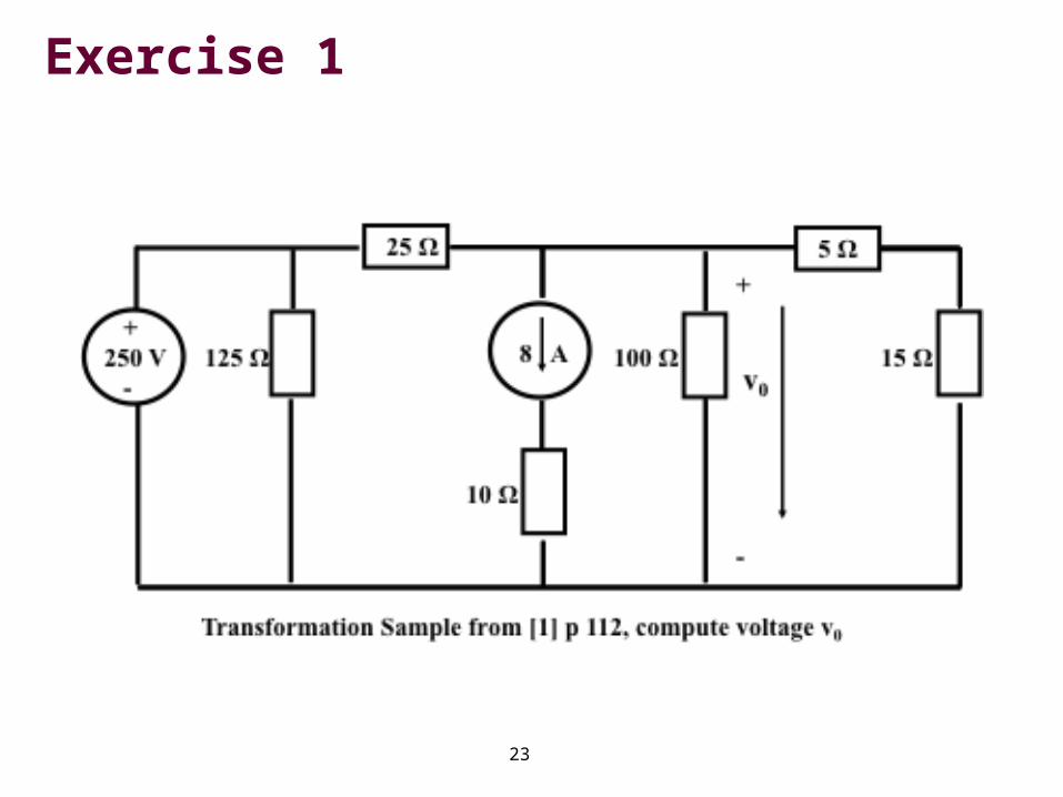
Taken from [1], page 112, Example 4.9, part a)
Given the circuit on the following page, compute the voltage drop v0 across the 100 Ω resistor
Solely using source transformations
Do not even resort to KCL or KVL, just simplify and then use Ohm’s Law
23
Exercise 1
24
Exercise 1
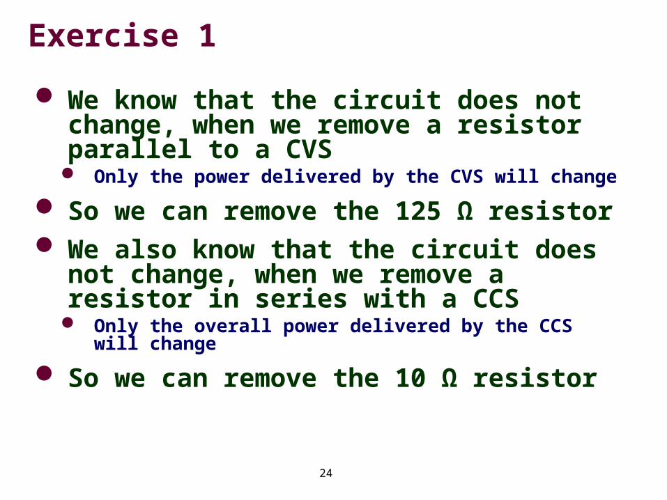
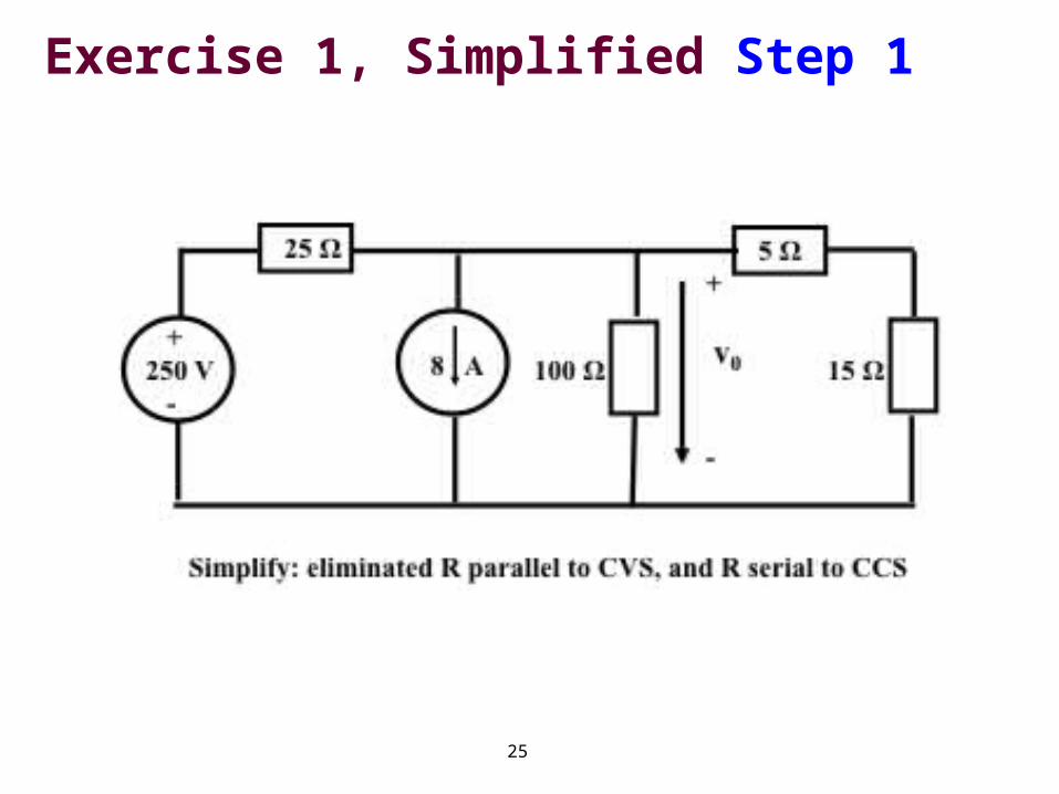
We know that the circuit does not change, when we remove a resistor parallel to a CVS
Only the power delivered by the CVS will change
So we can remove the 125 Ω resistor We also know that the circuit does
not change, when we remove a resistor in series with a CCS
Only the overall power delivered by the CCS will change
So we can remove the 10 Ω resistor
25
Exercise 1, Simplified Step 1
26
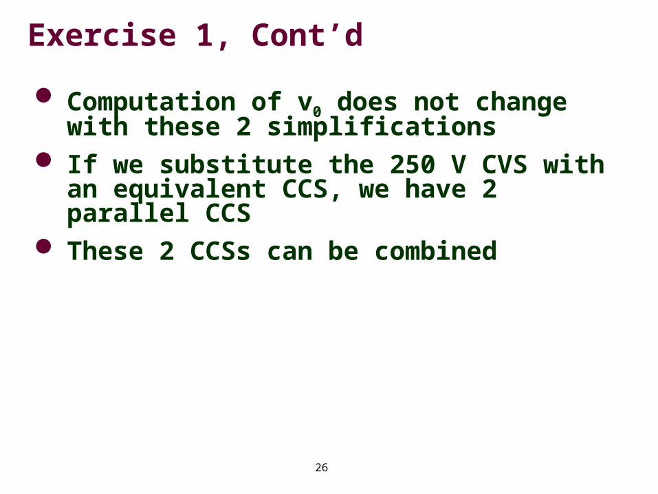
Exercise 1, Cont’d
Computation of v0 does not change with these 2 simplifications
If we substitute the 250 V CVS with an equivalent CCS, we have 2 parallel CCS
These 2 CCSs can be combined
27
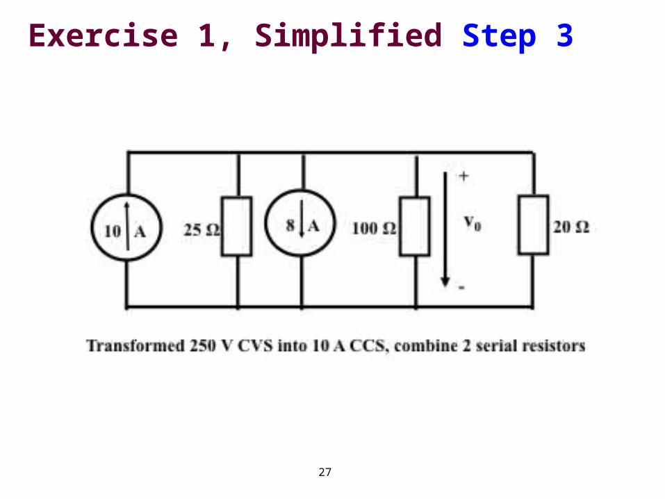
Exercise 1, Simplified Step 3
28
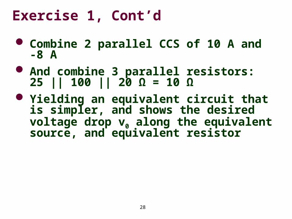
Exercise 1, Cont’d
Combine 2 parallel CCS of 10 A and -8 A
And combine 3 parallel resistors: 25 || 100 || 20 Ω = 10 Ω
Yielding an equivalent circuit that is simpler, and shows the desired voltage drop v0 along the equivalent source, and equivalent resistor
29
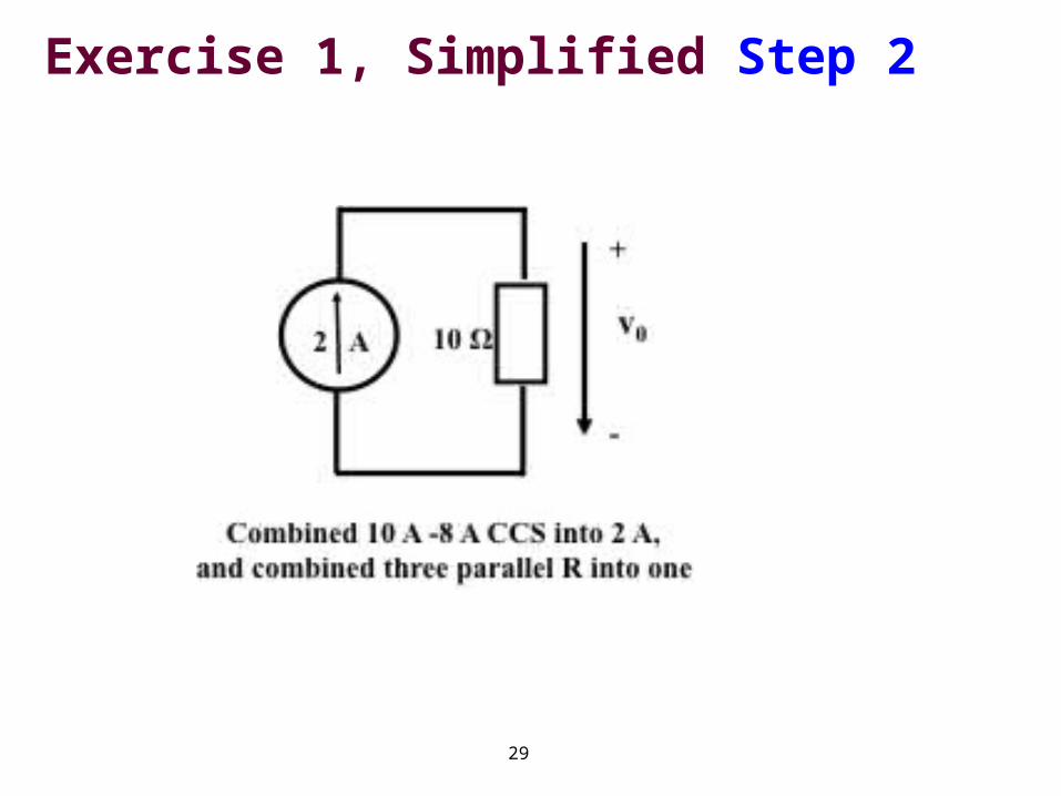
Exercise 1, Simplified Step 2
30
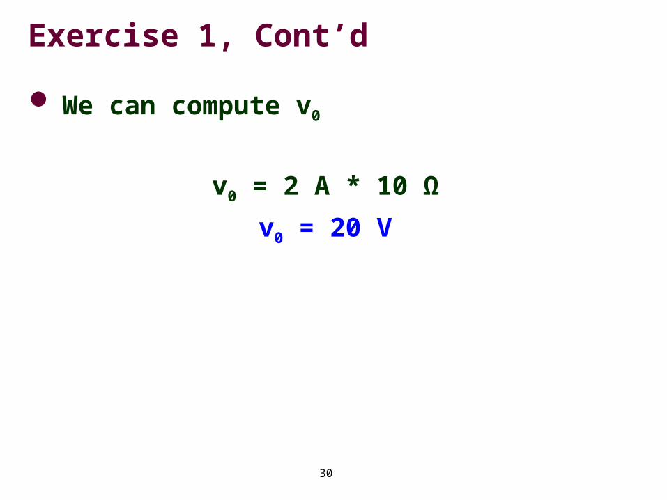
Exercise 1, Cont’d
We can compute v0
v0 = 2 A * 10 Ω
v0 = 20 V
31
Exercise 2, Compute Power of V 250
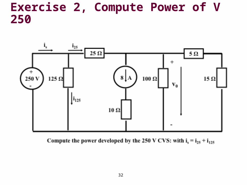
Next compute the power ps delivered (or if sign reversed: absorbed) by the 250 V CVS
The current delivered by the CVS is named is
And it equals the sum of i125 and i25
32
Exercise 2, Compute Power of V 250
33
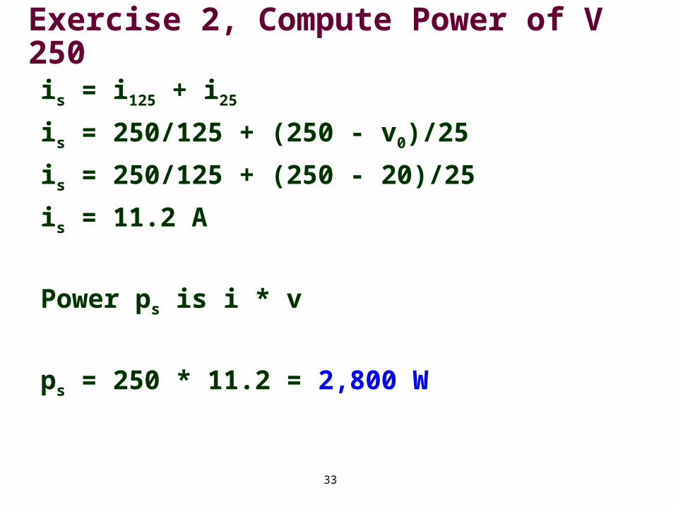
Exercise 2, Compute Power of V 250is = i125 + i25
is = 250/125 + (250 - v0)/25
is = 250/125 + (250 - 20)/25
is = 11.2 A
Power ps is i * v
ps = 250 * 11.2 = 2,800 W
34
Exercise 3, Compute Power of 8 A CCS
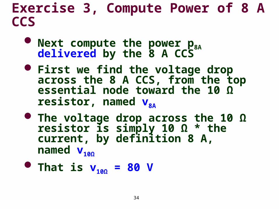
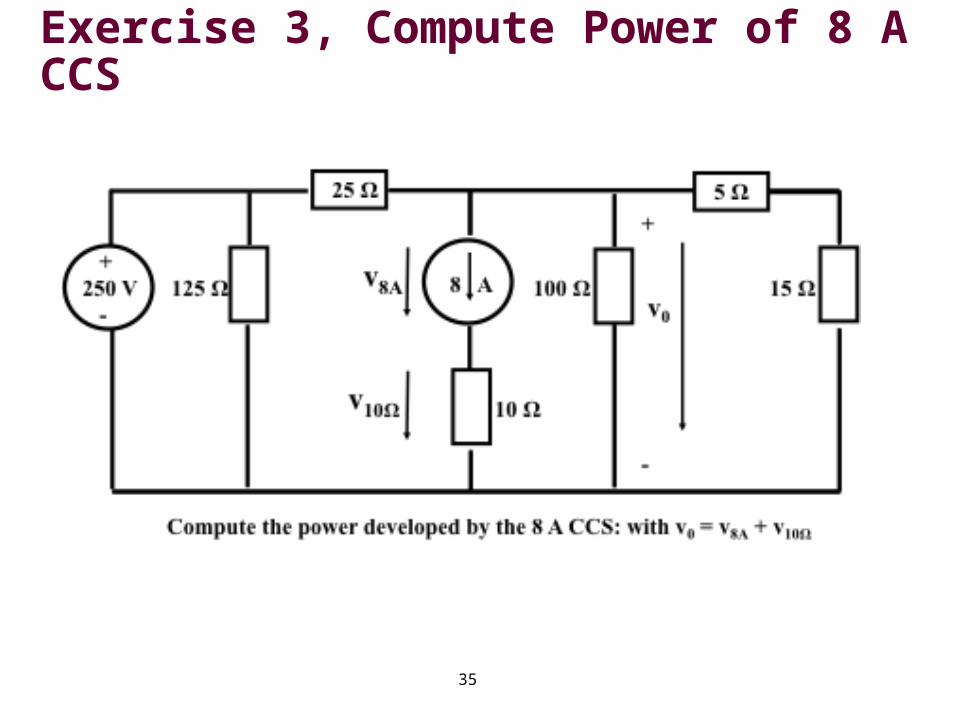
Next compute the power p8A delivered by the 8 A CCS
First we find the voltage drop across the 8 A CCS, from the top essential node toward the 10 Ω resistor, named v8A
The voltage drop across the 10 Ω resistor is simply 10 Ω * the current, by definition 8 A, named v10Ω
That is v10Ω = 80 V
35
Exercise 3, Compute Power of 8 A CCS
36
Exercise 3, Compute Power of 8 A CCS
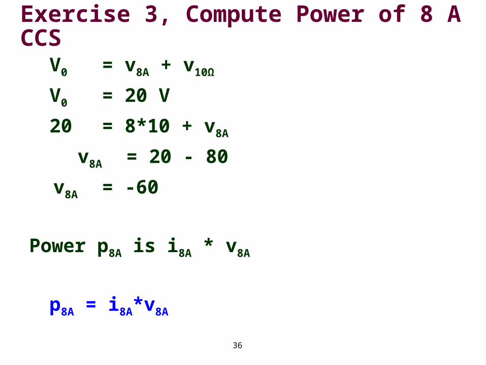
V0 = v8A + v10Ω
V0 = 20 V
20 = 8*10 + v8A
v8A = 20 - 80
v8A = -60
Power p8A is i8A * v8A
p8A = i8A*v8A