Embed Size (px)
Citation preview
1
Dimension Terminology:
2
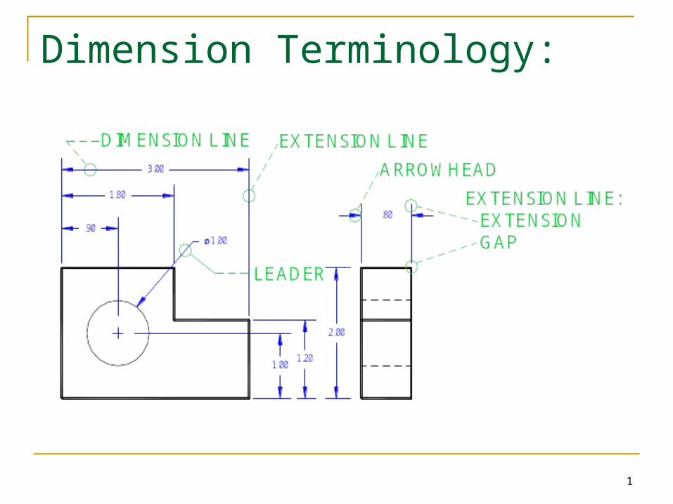
Extension lines Extension lines should be offset from the part by one half the text height and should extend one text height beyond the dimension line
3
Dimension Spacing
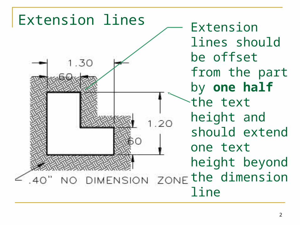
The first row of dimensions must be a minimum of 3 text heights away from the part.Any dimensions beyond it must be a minimum of 2 text heights apart
4
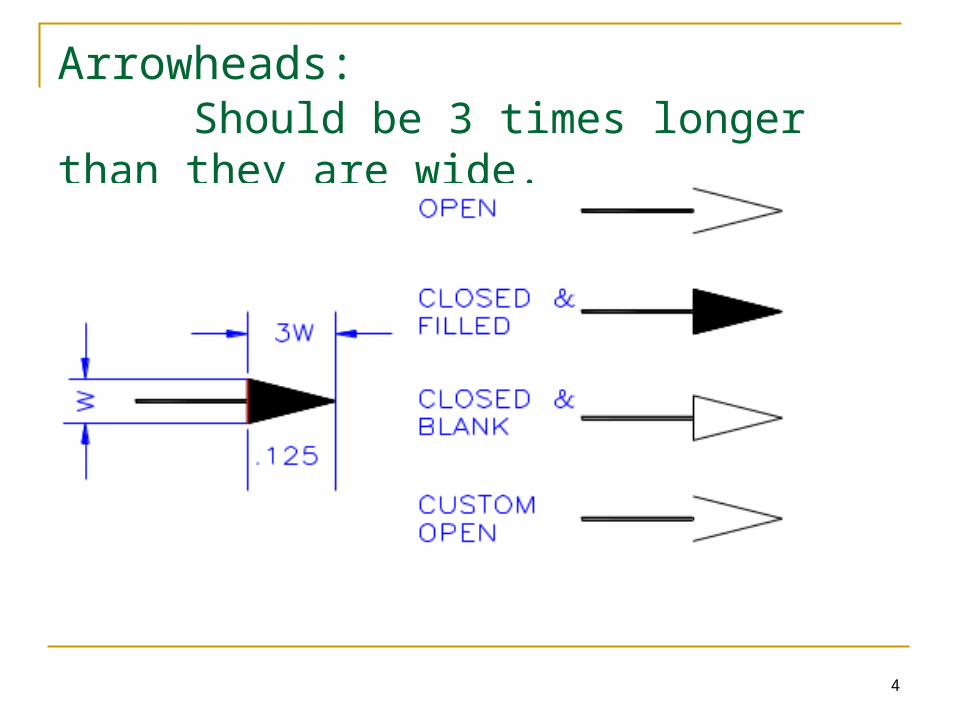
Arrowheads: Should be 3 times longer than they are wide.
5
Dimensioning Rules Avoid placing any dimensions on
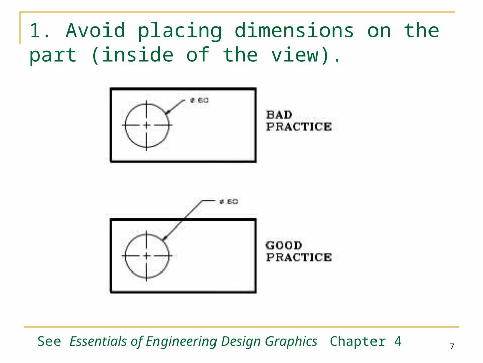
the part (inside the view) unless there is no other option.
Avoid dimensioning to hidden features
Always place the dimension where the characteristic shape is shown in the most descriptive view. (This means don’t place a dimension on object lines making a “T joint”.)
Always dimension holes in their circular view by stating the diameter of drilled holes. Specify the hole depth of special features such as countersinking with a note following the dimension.
Dimension rounded corners and arc features as radii where they appear in their rounded views.
If the same value is repeated many times, then use a general note for the features.
Dimension cylindrical objects as diameters in their rectangular view.
Always place the first row of dimensions a minimum distance of 3 text heights away from the edge of the part. Additional stacks can be a minimum of 2 text heights away from each other.
Keep dimensions between the views whenever possible
Extension lines may cross each other and over other lines on the part, but dimension lines should never be crossed.
The overall dimension should always be given. It should be placed outside of smaller dimensions and be the furtherest dimension from the part.
See Essentials of Engineering Design Graphics Chapter 4
6
Do not duplicate dimensions and avoid using unnecessary or superfluous dimensions
When all of the dimensions are expressed in inches, do not use inch mark (“) or the abbreviation for inches (in.)
For drawings dimensioned in inches, values less that one inch should not be preceded with a zero.
For metric drawings, omit the use of the millimeter (mm) notation following the numeral, as millimeters are the default units.
The origin for baseline or ordinate dimensions used as a datum should be extended from a finished edge of the part.
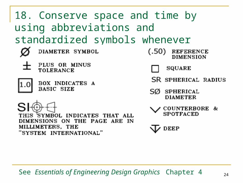
Conserve space and time by using abbreviations and standardized symbols whenever possible.
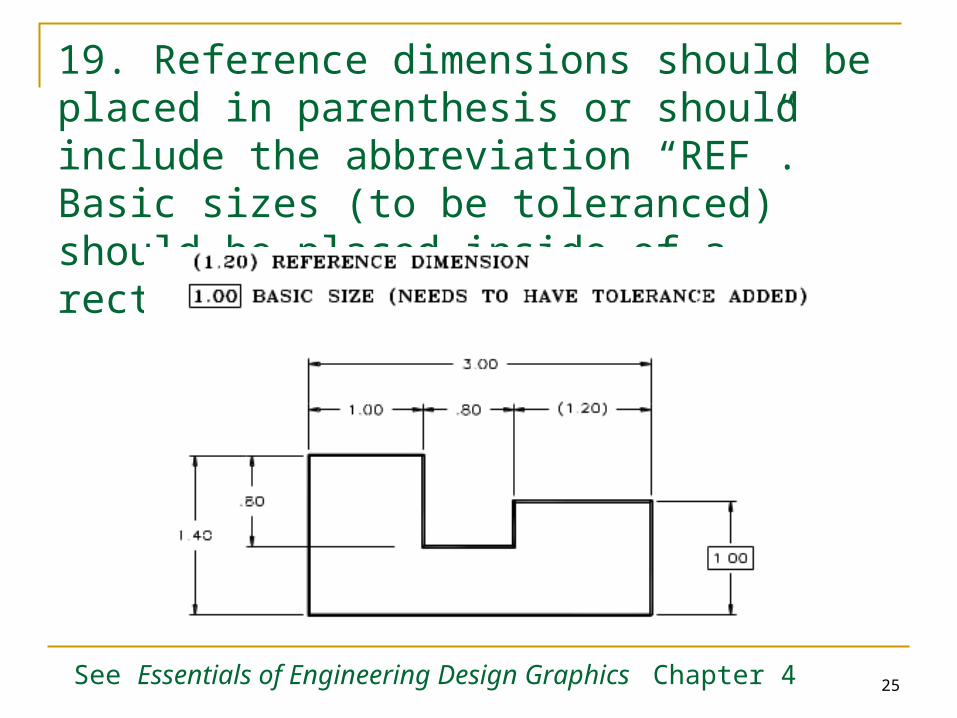
Reference dimensions should be placed in parentheses or should include the abbreviation “REF”.
Basic sizes (to be toleranced) should be placed inside a rectangular box
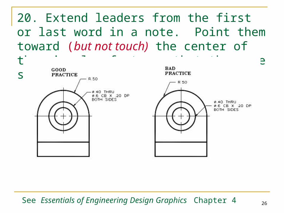
Extend leaders from the first of last word in a note. Point them toward the center of circular features that they are specifying.
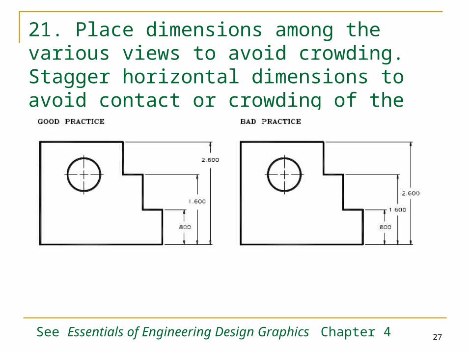
Place dimensions among the various views to avoid crowding. Stagger horizontal dimensions to avoid contact or crowding of values.
Dimensioning Rules
See Essentials of Engineering Design Graphics Chapter 4
7
1. Avoid placing dimensions on the part (inside of the view).
See Essentials of Engineering Design Graphics Chapter 4
8
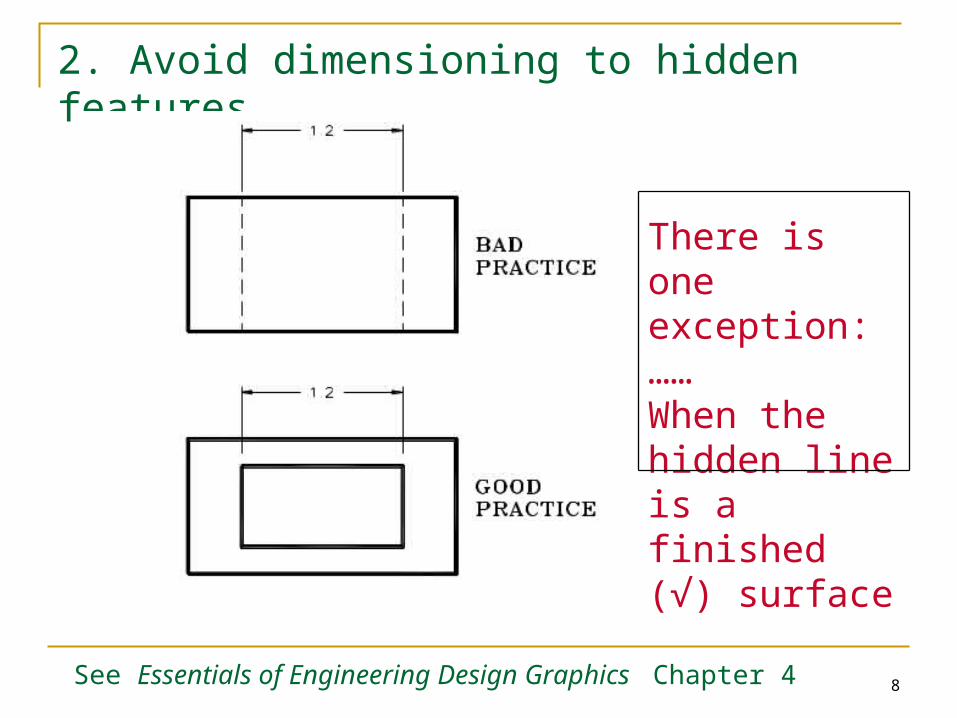
2. Avoid dimensioning to hidden features
There is one exception:……When the hidden line is a finished (√) surface
See Essentials of Engineering Design Graphics Chapter 4
9
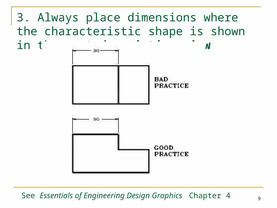
3. Always place dimensions where the characteristic shape is shown in the most descriptive view
See Essentials of Engineering Design Graphics Chapter 4
10
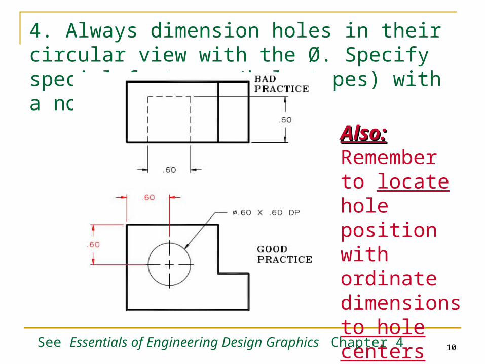
4. Always dimension holes in their circular view with the Ø. Specify special features (hole types) with a note.
Also:Also: Remember to locate hole position with ordinate dimensions to hole centers
See Essentials of Engineering Design Graphics Chapter 4
11
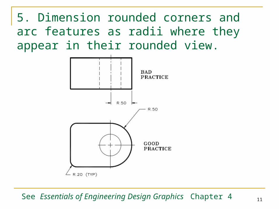
5. Dimension rounded corners and arc features as radii where they appear in their rounded view.
See Essentials of Engineering Design Graphics Chapter 4
12
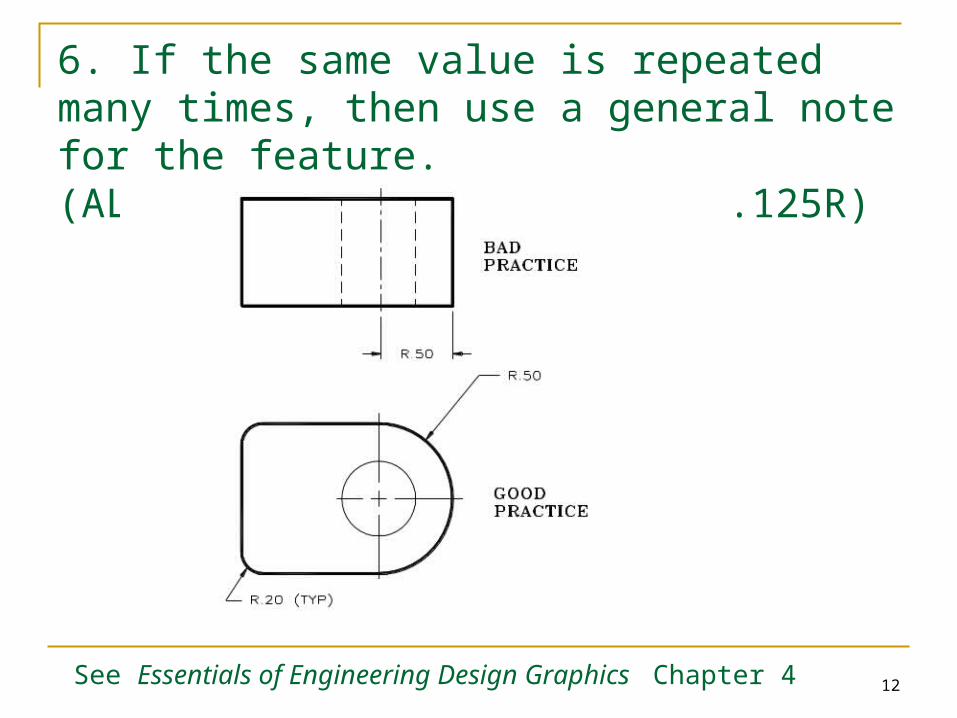
6. If the same value is repeated many times, then use a general note for the feature. (ALL FILLETS AND ROUNDS ARE .125R)
See Essentials of Engineering Design Graphics Chapter 4
13
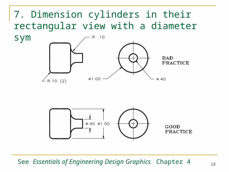
7. Dimension cylinders in their rectangular view with a diameter symbol….Ø.
See Essentials of Engineering Design Graphics Chapter 4
14
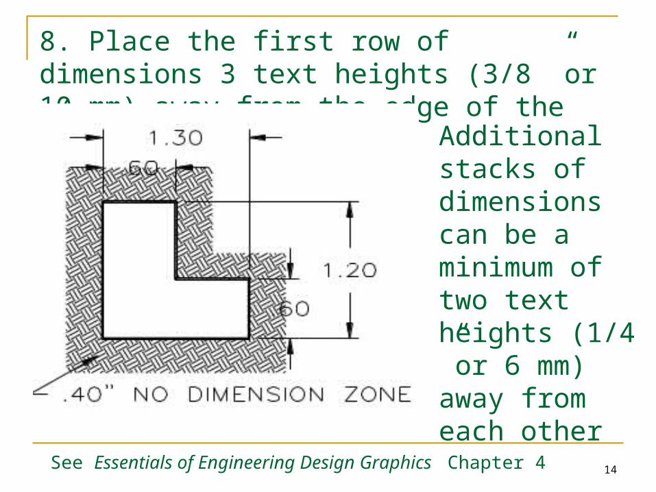
8. Place the first row of dimensions 3 text heights (3/8 ”or 10 mm) away from the edge of the part.
Additional stacks of dimensions can be a minimum of two text heights (1/4 ”or 6 mm) away from each other See Essentials of Engineering Design Graphics
Chapter 4
15
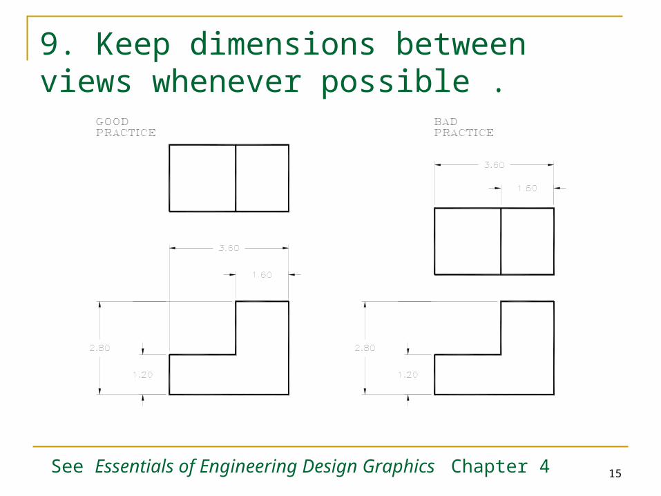
9. Keep dimensions between views whenever possible .
See Essentials of Engineering Design Graphics Chapter 4
16
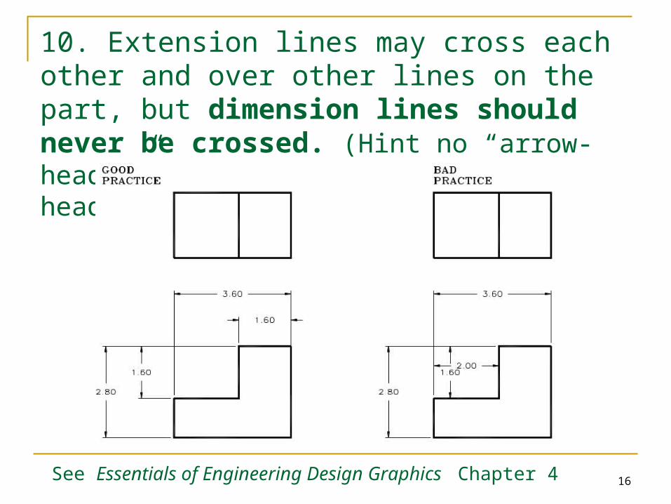
10. Extension lines may cross each other and over other lines on the part, but dimension lines should never be crossed. (Hint no “arrow-headed” lines can cross “arrow-headed” lines)
See Essentials of Engineering Design Graphics Chapter 4
17
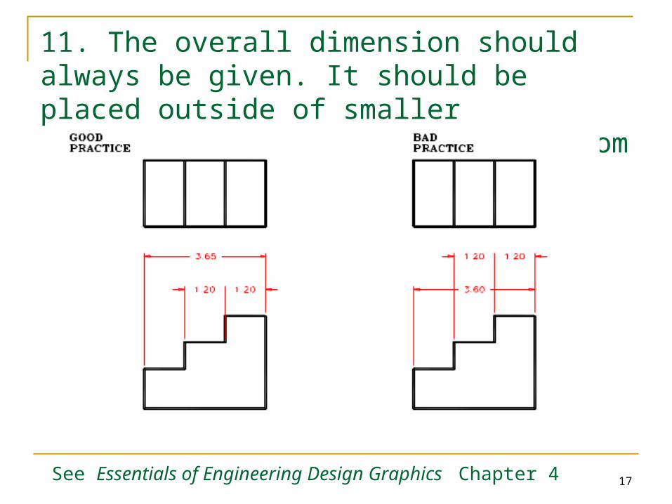
11. The overall dimension should always be given. It should be placed outside of smaller dimensions and be the farthest from the part.
See Essentials of Engineering Design Graphics Chapter 4
18
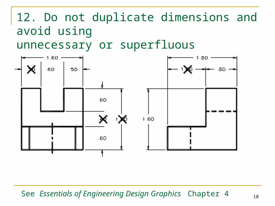
12. Do not duplicate dimensions and avoid using unnecessary or superfluous dimensions
See Essentials of Engineering Design Graphics Chapter 4
19
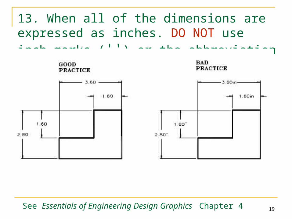
13. When all of the dimensions are expressed as inches. DO NOT use inch marks ('') or the abbreviation (.in)
See Essentials of Engineering Design Graphics Chapter 4
20
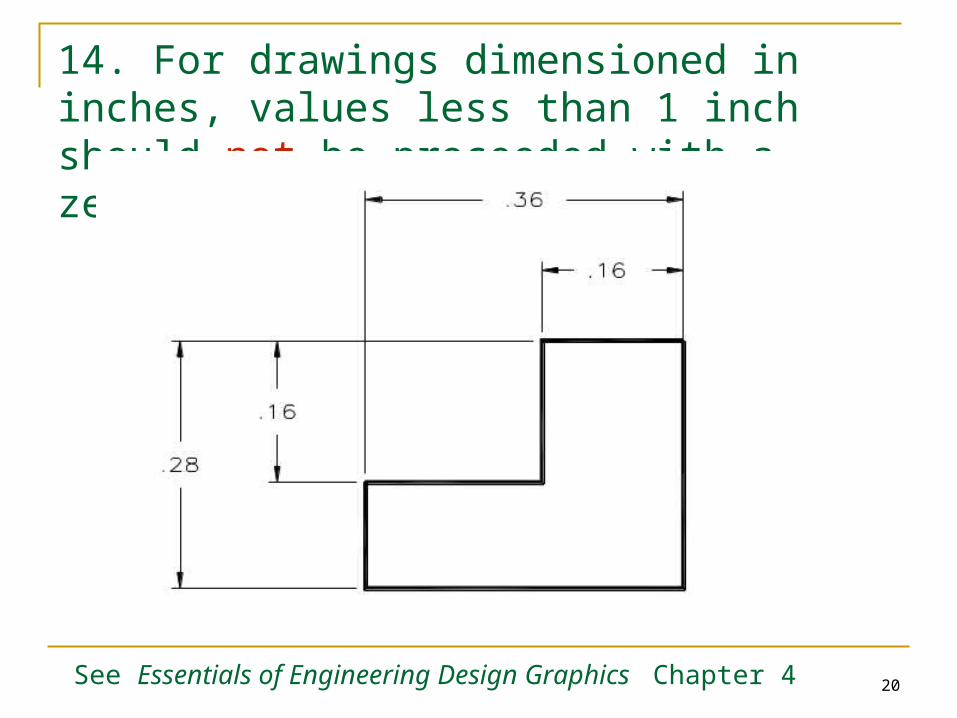
14. For drawings dimensioned in inches, values less than 1 inch should not be proceeded with a zero.
See Essentials of Engineering Design Graphics Chapter 4
21
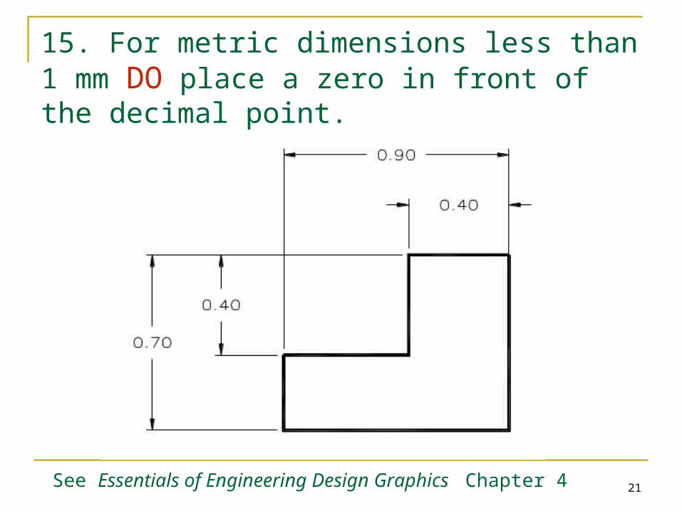
15. For metric dimensions less than 1 mm DO place a zero in front of the decimal point.
See Essentials of Engineering Design Graphics Chapter 4
22
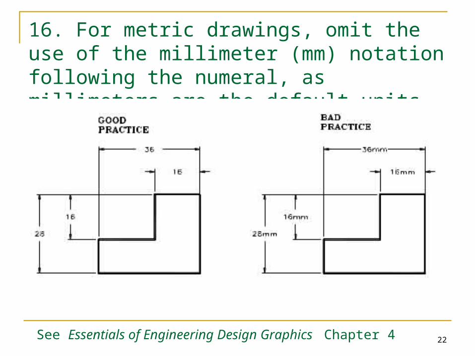
16. For metric drawings, omit the use of the millimeter (mm) notation following the numeral, as millimeters are the default units.
See Essentials of Engineering Design Graphics Chapter 4
23
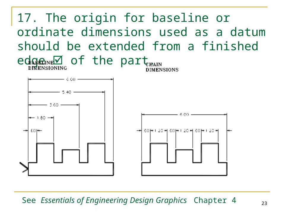
17. The origin for baseline or ordinate dimensions used as a datum should be extended from a finished edge of the part.
See Essentials of Engineering Design Graphics Chapter 4
24
18. Conserve space and time by using abbreviations and standardized symbols whenever possible.
See Essentials of Engineering Design Graphics Chapter 4
25
19. Reference dimensions should be placed in parenthesis or should include the abbreviation “REF”. Basic sizes (to be toleranced) should be placed inside of a rectangular box
See Essentials of Engineering Design Graphics Chapter 4
26
20. Extend leaders from the first or last word in a note. Point them toward (but not touch) the center of the circular features that they are specifying.
See Essentials of Engineering Design Graphics Chapter 4
27
21. Place dimensions among the various views to avoid crowding. Stagger horizontal dimensions to avoid contact or crowding of the values
See Essentials of Engineering Design Graphics Chapter 4
28
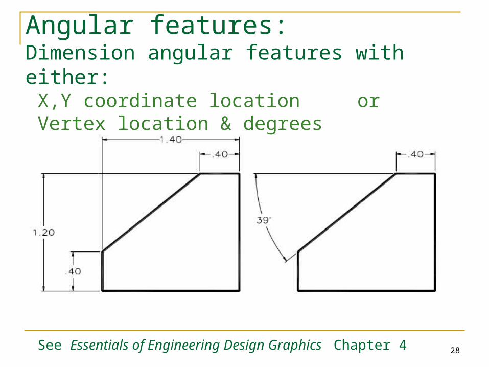
Angular features:Dimension angular features with either:
X,Y coordinate location or Vertex location & degrees
See Essentials of Engineering Design Graphics Chapter 4
29
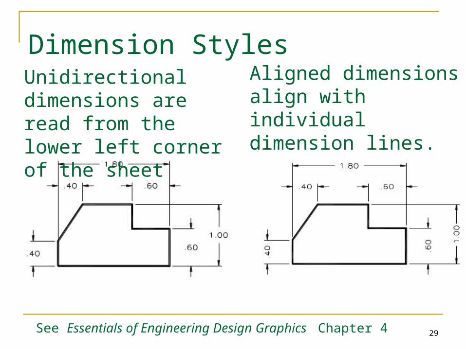
Dimension StylesUnidirectional dimensions are read from the lower left corner of the sheet
Aligned dimensions align with individual dimension lines.
See Essentials of Engineering Design Graphics Chapter 4
30
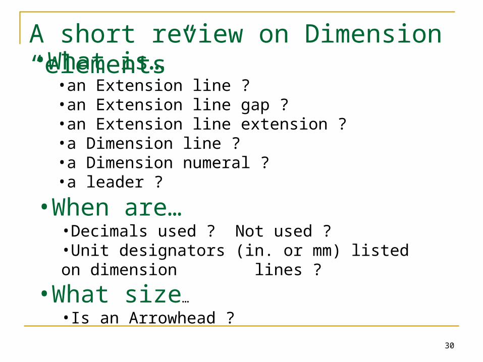
A short review on Dimension “elements”•What is…
•an Extension line ?•an Extension line gap ?•an Extension line extension ?•a Dimension line ?•a Dimension numeral ?•a leader ?
•When are…
•Decimals used ? Not used ?•Unit designators (in. or mm) listed on dimension lines ?
•What size…
•Is an Arrowhead ?
Dimensioning Dimensioning In AutoCADIn AutoCAD
32
Dimensioning in AutoCAD
AutoCAD does semi-automatic dimensioning You select the features which should be
dimensioned and the location for each dimension AutoCAD measures the distance in question and
applies the appropriate dimension complete with arrowheads, extension lines, and dimension lines
33
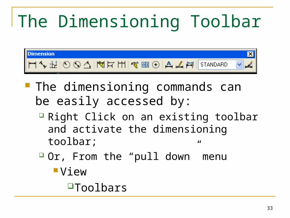
The Dimensioning Toolbar
The dimensioning commands can be easily accessed by: Right Click on an existing toolbar and
activate the dimensioning toolbar; Or, From the “pull down” menu
View
Toolbars
34
Linear Dimensions
Linear dimensions are use to show basic dimensions of parts
They can be orientated either in a horizontal or vertical (or even aligned) fashion
AutoCAD will automatically measure the length specified and insert all the parts of the dimension.
35
Leaders
Leaders are used to apply thread notes and other annotations
Leaders begin at the arrow and continue from their elbow to their annotation
The annotation can be any text string you want to type
36
Radius and Diameter
By selecting a circular feature (arc or circle) with the Radius or Diameter option AutoCAD will measure the size and place the dimension at a user selected point
Using the Center option will place automatic centerlines on arcs or circles
37
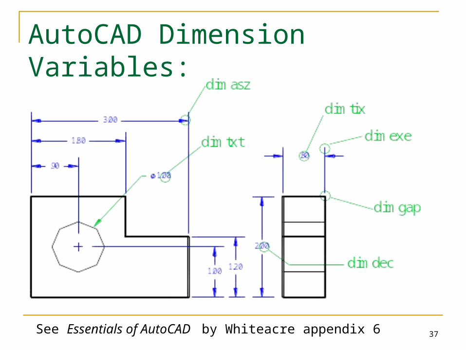
AutoCAD Dimension Variables:
See Essentials of AutoCAD by Whiteacre appendix 6
38
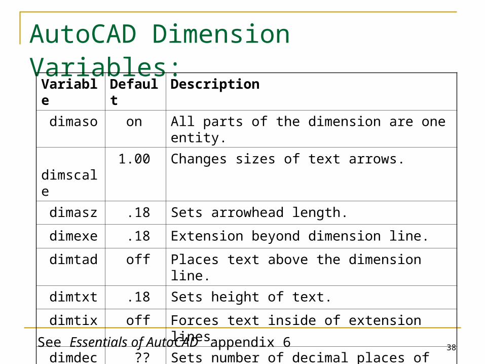
AutoCAD Dimension Variables:
Variable Default Description
dimaso on All parts of the dimension are one entity.
dimscale 1.00 Changes sizes of text arrows.
dimasz .18 Sets arrowhead length.
dimexe .18 Extension beyond dimension line.
dimtad off Places text above the dimension line.
dimtxt .18 Sets height of text.
dimtix off Forces text inside of extension lines.
dimdec ?? Sets number of decimal places of dimension
dimcen ?? Sets center tick mark size
See Essentials of AutoCAD appendix 6
39
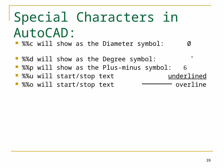
Special Characters in AutoCAD: %%c will show as the Diameter symbol: Ø %%d will show as the Degree symbol: %%p will show as the Plus-minus symbol: %%u will start/stop text underlined %%o will start/stop text overline
40
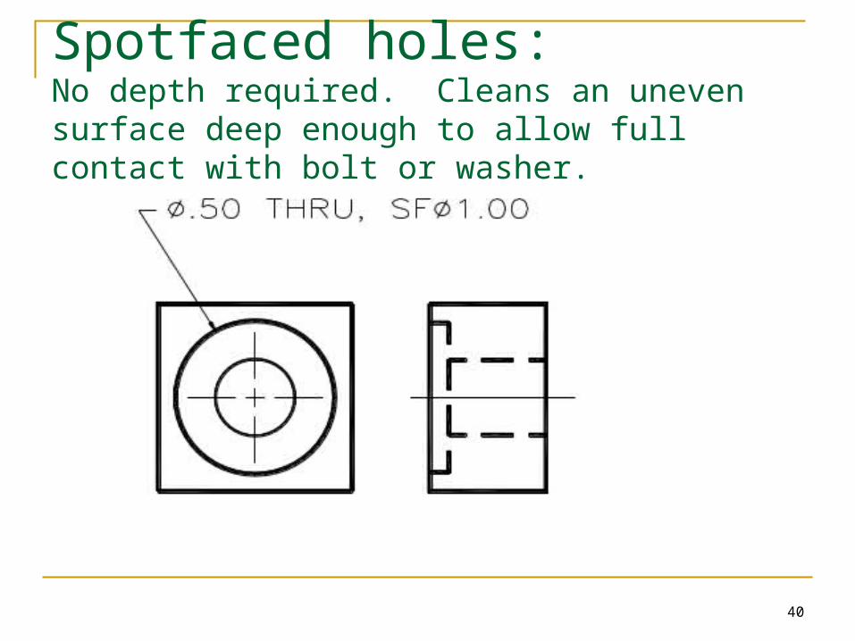
Spotfaced holes:No depth required. Cleans an uneven surface deep enough to allow full contact with bolt or washer.
41
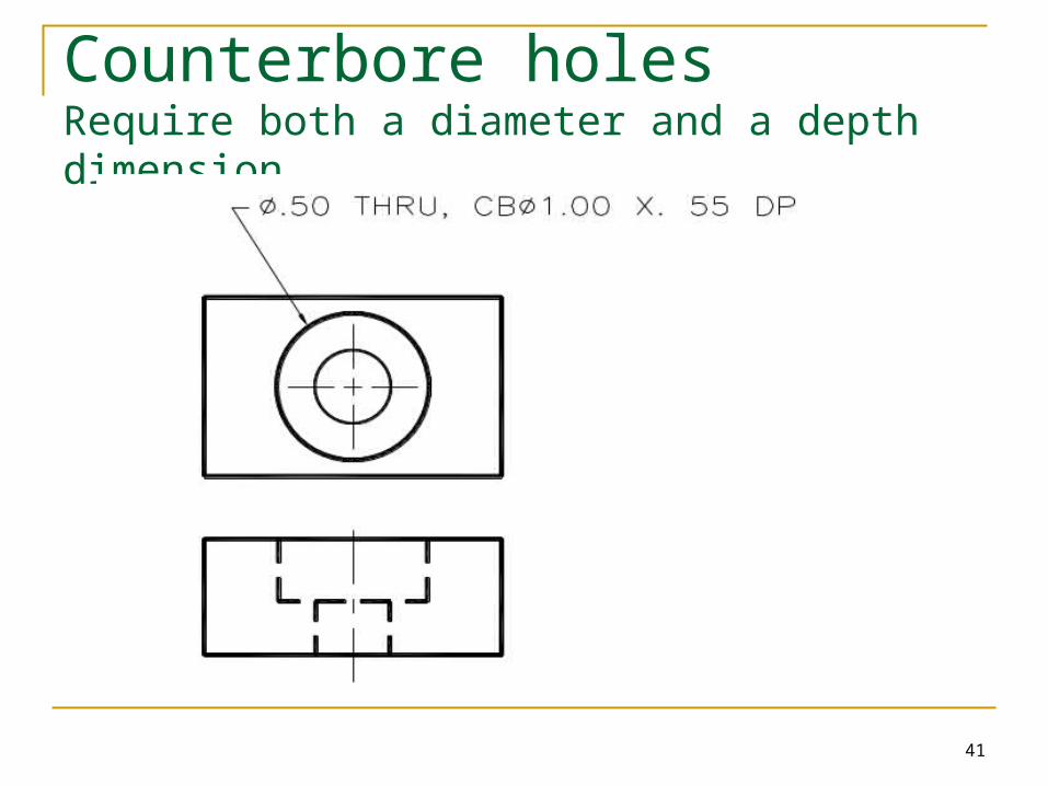
Counterbore holesRequire both a diameter and a depth dimension.
42
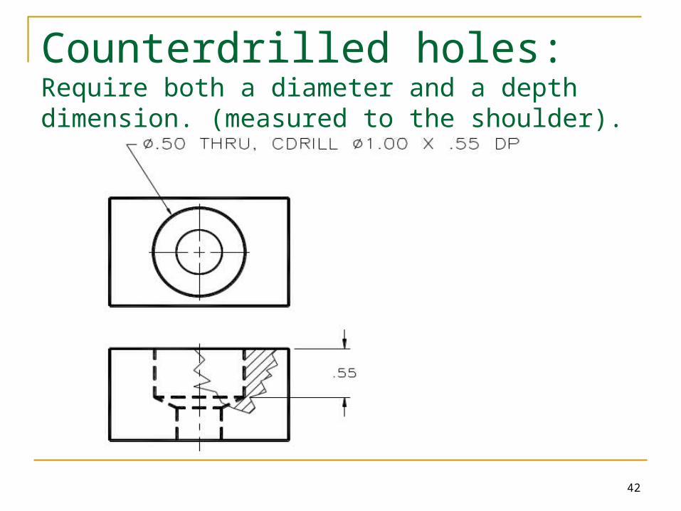
Counterdrilled holes:Require both a diameter and a depth dimension. (measured to the shoulder).
43
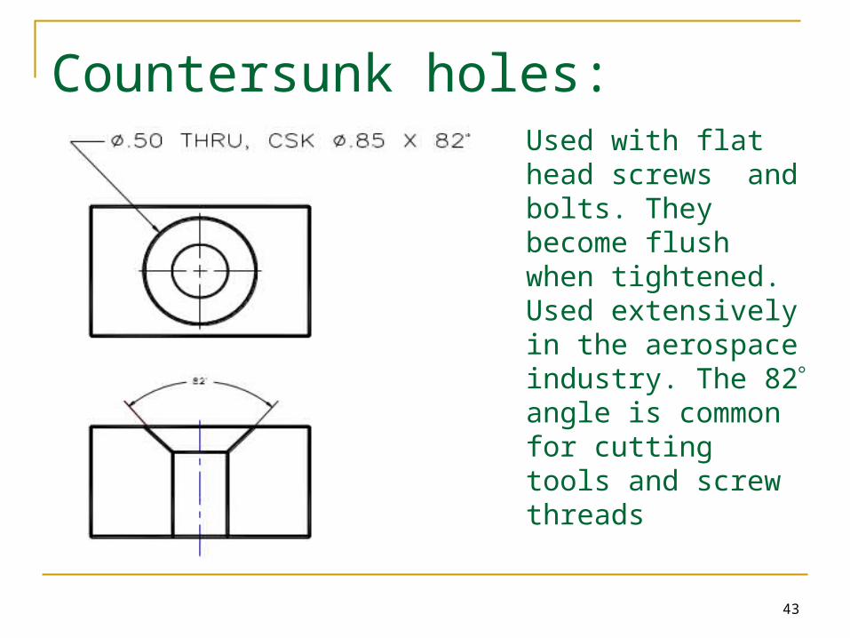
Countersunk holes:
Used with flat head screws and bolts. They become flush when tightened. Used extensively in the aerospace industry. The 82 angle is common for cutting tools and screw threads
44
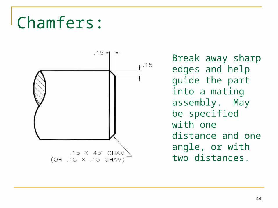
Chamfers:
Break away sharp edges and help guide the part into a mating assembly. May be specified with one distance and one angle, or with two distances.
45
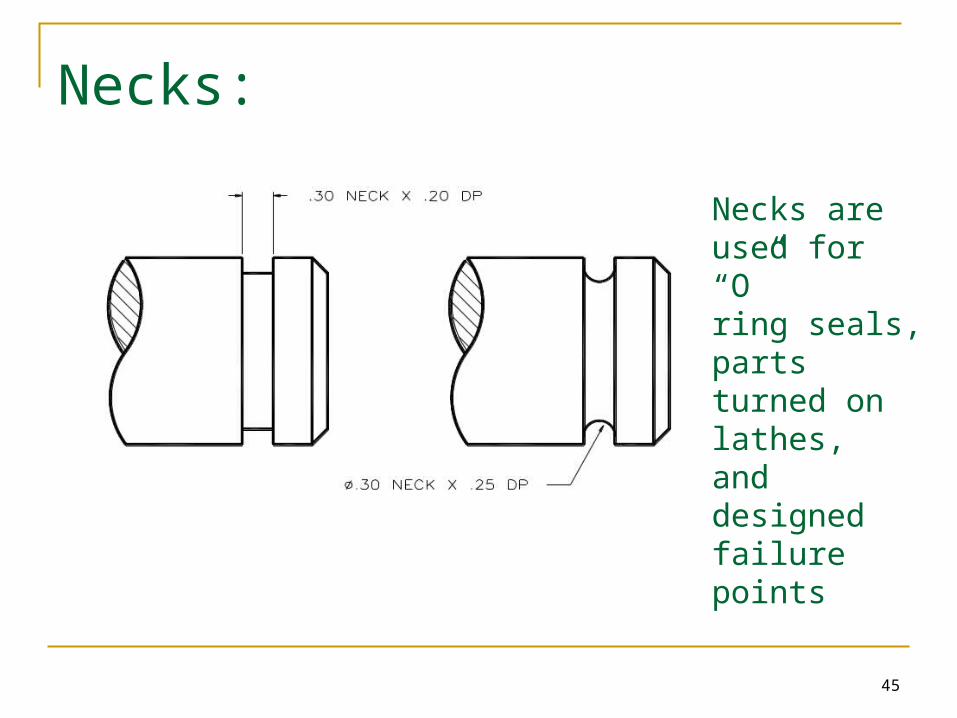
Necks:
Necks are used for “O”ring seals, parts turned on lathes, and designed failure points
46
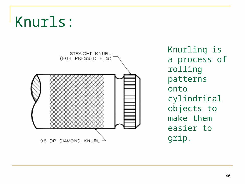
Knurls:
Knurling is a process of rolling patterns onto cylindrical objects to make them easier to grip.
47
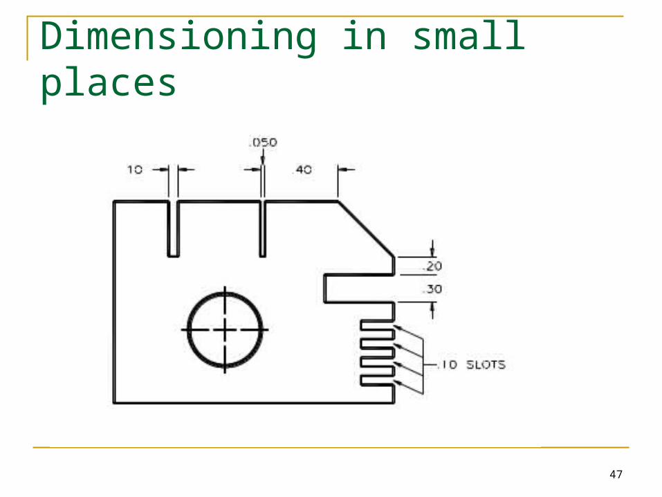
Dimensioning in small places
48
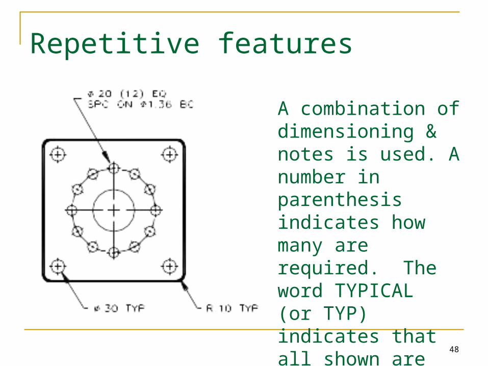
Repetitive features
A combination of dimensioning & notes is used. A number in parenthesis indicates how many are required. The word TYPICAL (or TYP) indicates that all shown are the same.
49
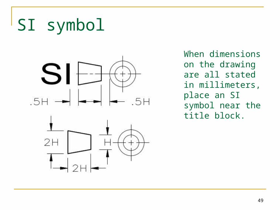
SI symbol
When dimensions on the drawing are all stated in millimeters, place an SI symbol near the title block.
50
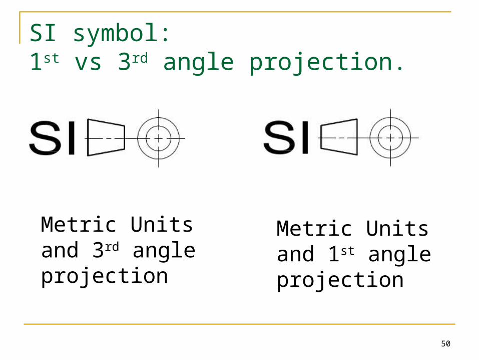
SI symbol: 1st vs 3rd angle projection.
Metric Units and 3rd angle projection
Metric Units and 1st angle projection
51
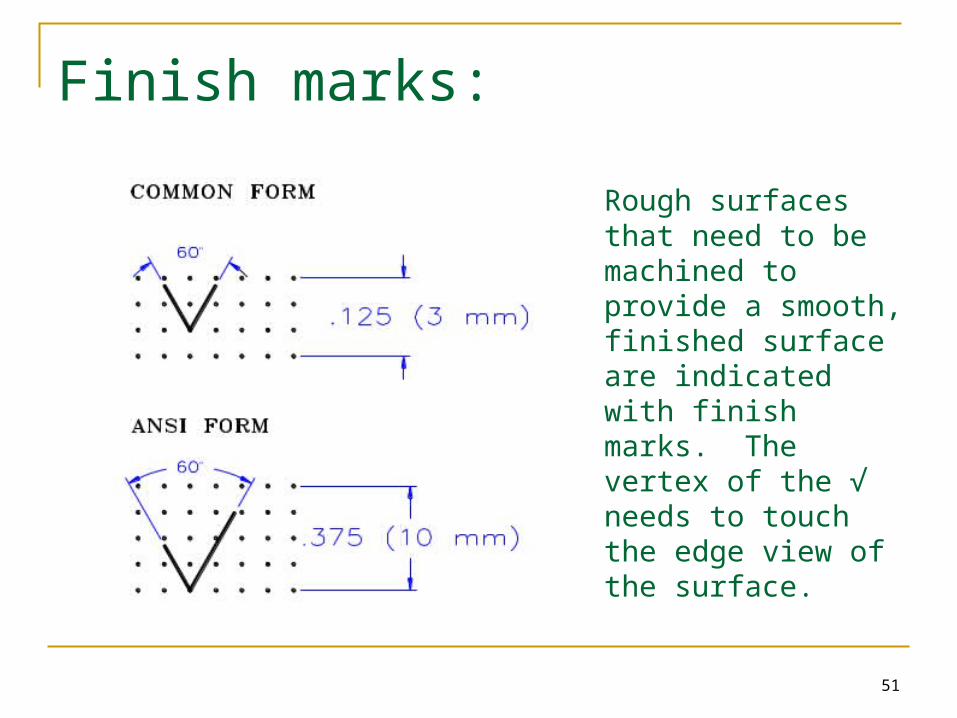
Finish marks:
Rough surfaces that need to be machined to provide a smooth, finished surface are indicated with finish marks. The vertex of the √ needs to touch the edge view of the surface.

52
Individual Assignment: AutoCAD
Plate 51………………..…….…all Plate 52……………………C & D Plate 53 …………….……..B & D Plate 54 ……………….…..A & D
Due: Beginning of class 12.2
Preview: Tolerances:………………. Plate 57-63
You will need your “paper copy” of the Vinson plate book for this assignment
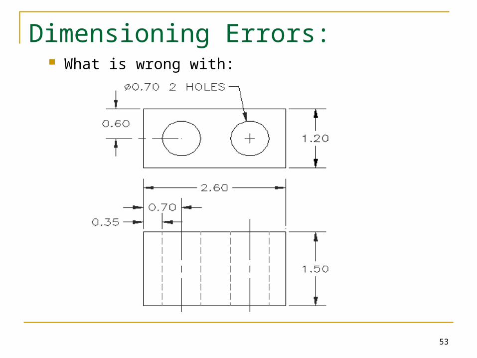
53
Dimensioning Errors: What is wrong with:
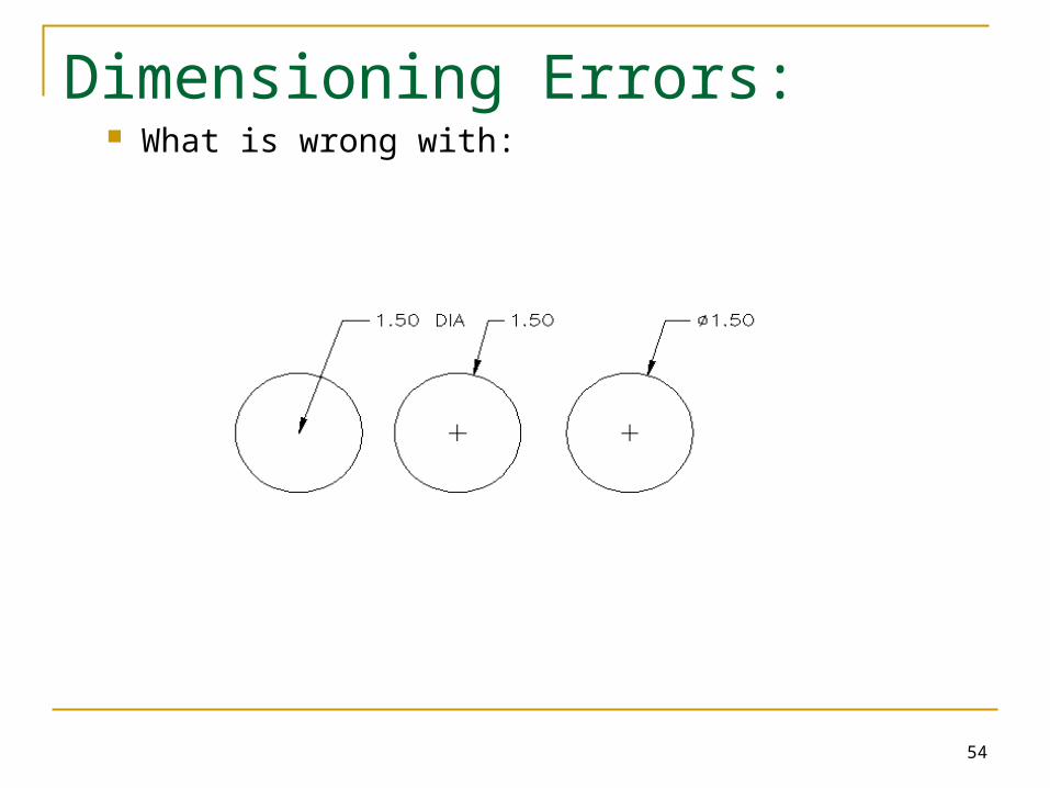
54
Dimensioning Errors: What is wrong with:
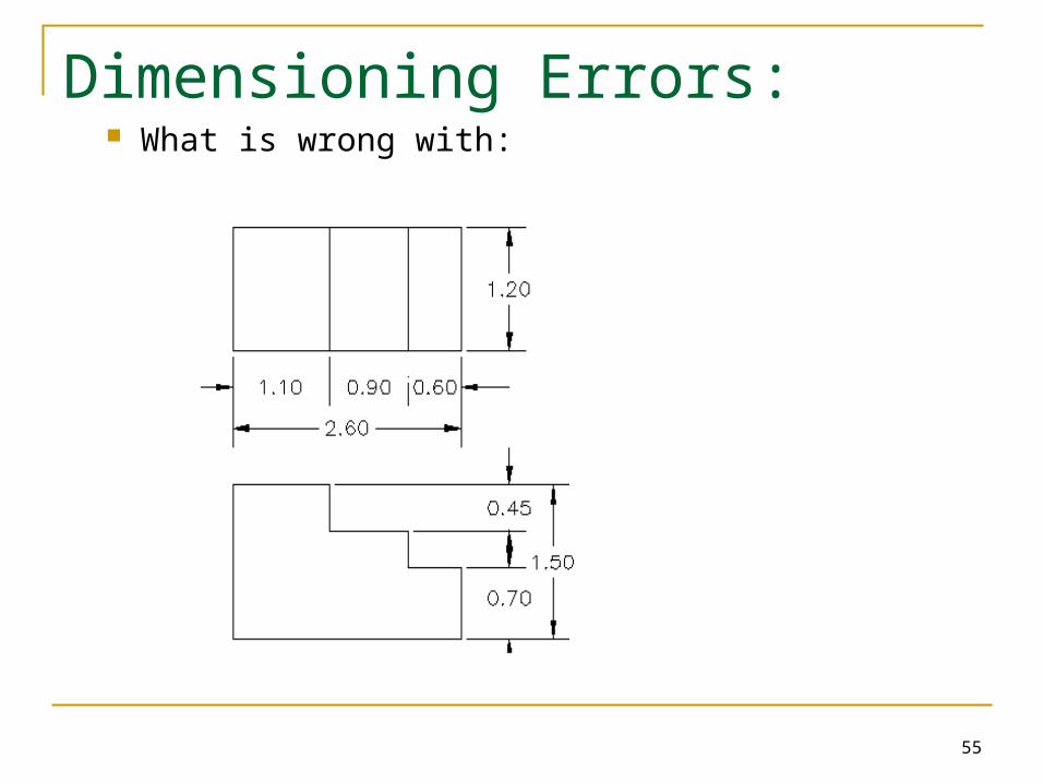
55
Dimensioning Errors: What is wrong with:
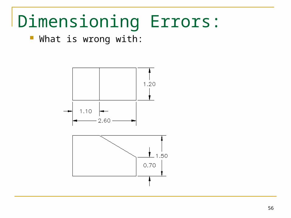
56
Dimensioning Errors: What is wrong with: