Embed Size (px)
Citation preview
T H E A R C H I V E O F M E C H A N I C A L E N G I N E E R I N G
VOL. LVIII 2011 Number 1
10.2478/v10180-011-0007-5Key words: robot, rehabilitation device, lower extremities rehabilitation, compliance control
MARCIN KACZMARSKI ∗, GRZEGORZ GRANOSIK ∗
REHABILITATION ROBOT RRH1
The paper presents a prototype of a rehabilitation robot for lower extremities. Itis created on the basis of cylindrical kinematic model, equipped with two rigid arms,special handles and fixtures. It has five active degrees of freedom and is designedto repeat the trajectories generated by physiotherapist during the learning phase.Presented prototype of rehabilitation robot has the ability to replay different types oftrained exercises such as: hip and knee flexion/extension, leg abduction/adduction.The protection system (including overload detection) implemented in the robot en-sures safe working with patients.
1. Development of rehabilitation robotic devices for lower extremities
The beginnings of lower extremities rehabilitation with motor-assisteddevices is dated on seventies of XX century. At this time the concept ofcontinuous passive motion rail has been tested. This kind of mechanicalstructure evaluated from the work of Robert B. Salter – an orthopedic surgeon– who noted that the cyclical flexion-extension of patient’s joint reducesrecovery time and increases their range of motion after orthopedic surgery.These devices are designed in two types, for upper limb and lower limbrehabilitation, as shown in Fig. 1.
Rapid technology revolution in the field of electronics and control sys-tems increased the number of semi-automatic and automatic devices installedand used in rehabilitation clinics, mainly due to their new therapeutic proper-ties [7]. Applying an electronic control system allows the user to adjust somebasic parameters such as: the range and speed of motion. It also provides acompliance control which prevents from excessive force acting on rehabili-tated joint. Moreover, with the progress of therapy the device performs anautomatic increase in range of motion.
∗ Technical University of Lodz, Institute of Automatic Control, ul. Stefanowskiego 18/22,90-924 Łódź, Poland; e-mail: [email protected], [email protected]
104 MARCIN KACZMARSKI, GRZEGORZ GRANOSIK
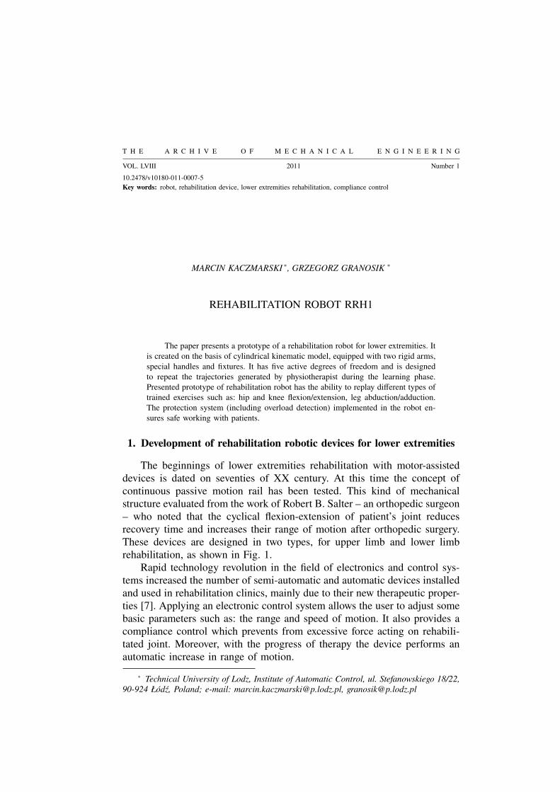
Fig. 1. CPM rails: a – for upper limb rehabilitation, b – for lower extremities rehabilitation,
reproduced from [http://www.abledata.com]
Various designs allow the rehabilitation process being realized in stand-ing, sitting, or lying position of the patient. However, the important limitationof these devices is fact that they are able to work in a single plane only.Therefore, changing the rehabilitation procedure very often requires movingpatient to the different position or setting new orientation of the mechanicaldevice. On the other hand, the main advantage of leg rehabilitation CPMrails is their low weight and relatively low cost.
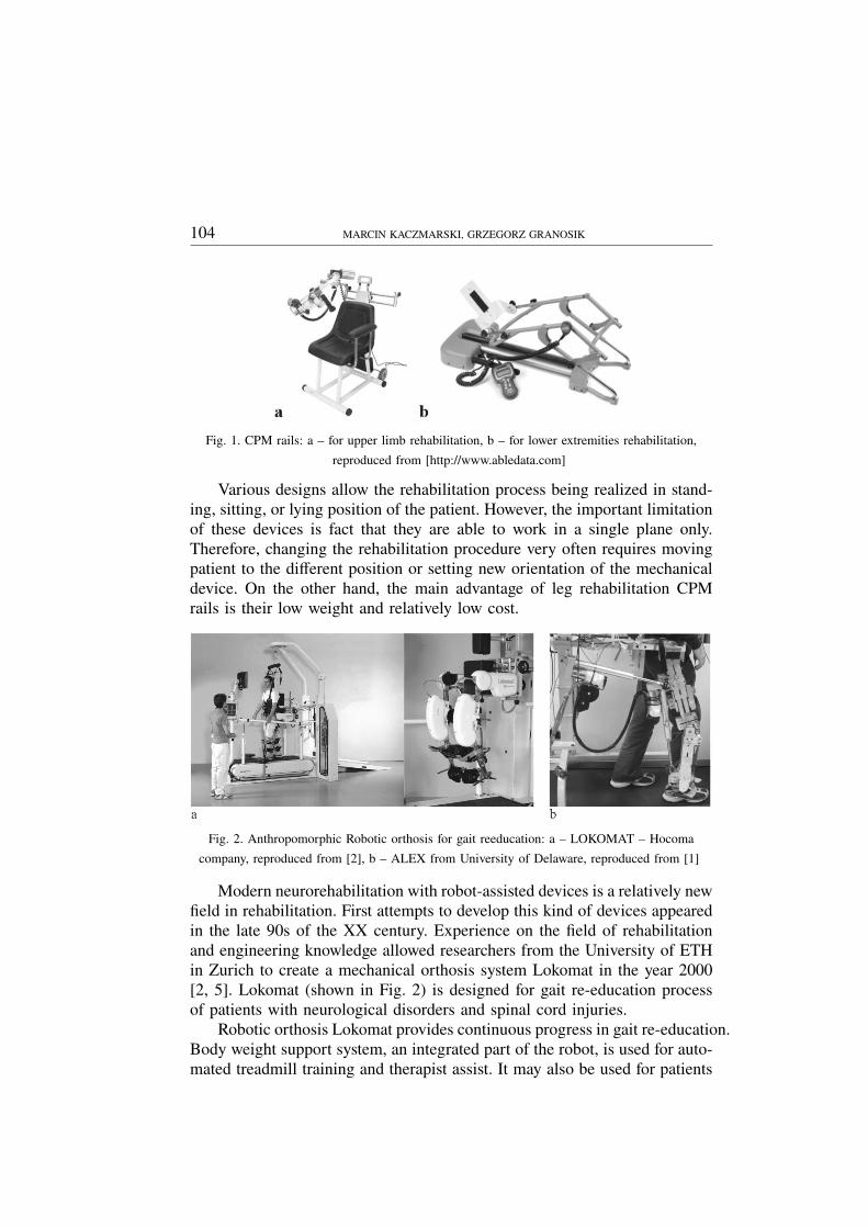
Fig. 2. Anthropomorphic Robotic orthosis for gait reeducation: a – LOKOMAT – Hocoma
company, reproduced from [2], b – ALEX from University of Delaware, reproduced from [1]
Modern neurorehabilitation with robot-assisted devices is a relatively newfield in rehabilitation. First attempts to develop this kind of devices appearedin the late 90s of the XX century. Experience on the field of rehabilitationand engineering knowledge allowed researchers from the University of ETHin Zurich to create a mechanical orthosis system Lokomat in the year 2000[2, 5]. Lokomat (shown in Fig. 2) is designed for gait re-education processof patients with neurological disorders and spinal cord injuries.
Robotic orthosis Lokomat provides continuous progress in gait re-education.Body weight support system, an integrated part of the robot, is used for auto-mated treadmill training and therapist assist. It may also be used for patients
REHABILITATION ROBOT RRH1 105
that required to be lifted out of the wheelchair. Regarding inertial forces thatmay affect patients during vertical movements, traditional counterweight sys-tems could not be used during therapy. Lokomat is equipped with a computerdriven unloading unit that imitates patient’s movements during gait cycle andalso provides regulation of contact forces during walking on treadmill.
During robot-assisted therapy the optimum number of repetitions of gaitcycles is performed according to the programmed pattern. The specializedsoftware provides adjustable range of motion for individual patients (regard-ing hip and knee joints), variable velocity of movements, and synchronizationof the walking cycles with the treadmill speed. Universal mechanical modulesand handles implemented in the construction of robotic legs allow for preciseadaptation to the anatomy of different patients.
All over the world researchers are also working to develop similar de-vices. However, they did not go beyond the stage of prototypes and mostof the constructions haven’t been commercialized yet. The similar designto the Lokomat has been recently developed at the University of Delaware,Newark USA. Its name ALEX states for Active Leg Exoskeleton and it canbe recognized by the larger number of degrees of freedom and the passivegravity compensation system, as shown in Figure 2b [1]. Mechanical orthosisleg has 3 active degrees of freedom corresponding to the bending move ofthe knee and the hip in sagittal plane. Additionally, orthosis has one degreeof freedom responsible for adduction and abduction movements of the leg.
The whole mechanism is attached to the supporting structure with twopassive degrees of freedom, which provide additional vertical and horizontalmovements. Elastic elements used in construction of passive joints are usedfor compensation of the brace’s weight, and perform the proper movementsof the pelvis (lateral, vertical and rotation).
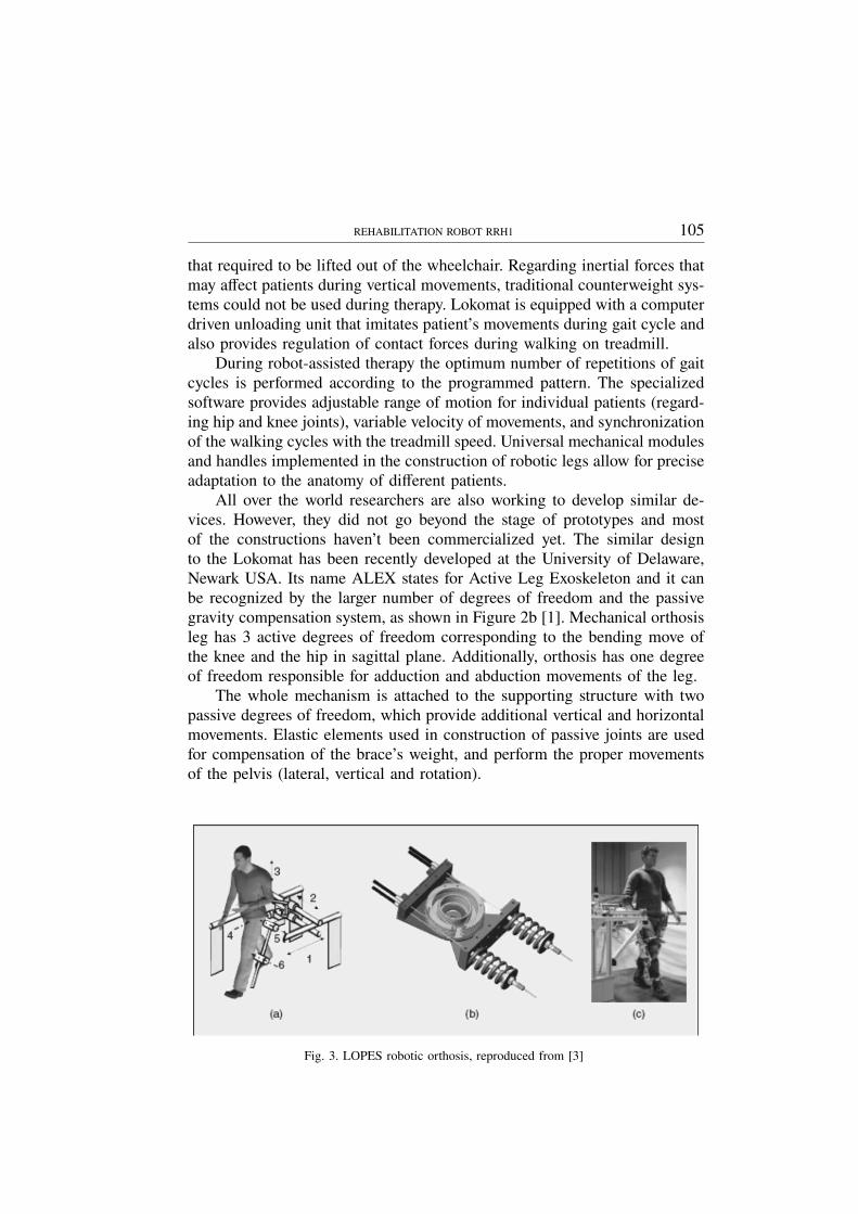
Fig. 3. LOPES robotic orthosis, reproduced from [3]
106 MARCIN KACZMARSKI, GRZEGORZ GRANOSIK
Structurally very similar to previous devices is LOPES – Lower-ExtremityPowered Exoskeleton, shown in Fig. 3, which is designed for the gait reha-bilitation purposes and uses treadmill in training procedure [3]. The mainobjectives of this project are: reducing the load of the physical therapistto improve the effectiveness of training in stroke patients and supportingselected elements of the locomotion apparatus in the process of gait re-education. Generating the movement of robotic orthosis is done according tothe programmed trajectory. During training process the interaction betweenthe patient and mechanical skeleton is taken into account. The compliant andadaptive control with adjustable serial elasticity in motor drives (shown inFig. 3b) is applied for active joints of the exoskeleton [9, 10]. This solutionallows patients to sense the minimal influence of mechanical orthosis to therehabilitated limbs. Comparing to the commercial Lokomat, orthosis LOPEShas larger number of active degrees of freedom. This provides free move-ments of the hip along three axes, indicated by 1, 2, and 3 in Fig. 3a. Firstand the second joint are active with servomotors while the vertical directionmarked as 3 is a passive one (without drive).
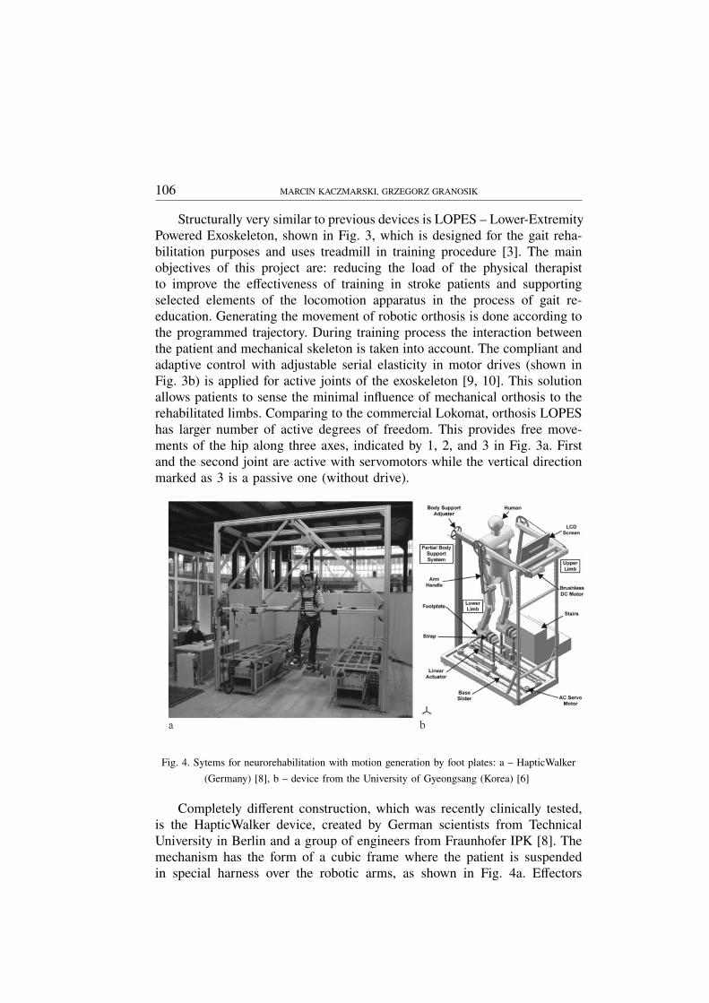
Fig. 4. Sytems for neurorehabilitation with motion generation by foot plates: a – HapticWalker
(Germany) [8], b – device from the University of Gyeongsang (Korea) [6]
Completely different construction, which was recently clinically tested,is the HapticWalker device, created by German scientists from TechnicalUniversity in Berlin and a group of engineers from Fraunhofer IPK [8]. Themechanism has the form of a cubic frame where the patient is suspendedin special harness over the robotic arms, as shown in Fig. 4a. Effectors
REHABILITATION ROBOT RRH1 107
of the robot arms are made as the special platforms with the handles toattach patient’s feet. The movements of the lower extremities are generatedby pushing or pulling of patient’s feet, as it is done in the CPM rails. Inthe HapticWalker device, the patient is supported by the dynamic weightcompensation system. Generating leg’s movements by acting on the patient’sfeet provides some extended possibilities to obtain more natural walking andstair climbing. This method of therapy involves not only the lower limbs butalso the entire body. The first tests showed that therapy with HapticWalkerincreases the strength and efficiency of the body. Increasing these parametersis one of the fundamental aspects in convalescence and prepares people toreturn to the duties and activities of everyday life. However, acting only onthe feet without additional constrains on knees and hips may lead to the situ-ation where motion in one direction can result in pathological compensatorymovements.
Another design of robotic system for lower extremities rehabilitationbased on same approach of motion generation by foot plates is the robotshown in Fig. 4b, developed by a team from Gyeongsang University in Ko-rea [6]. This robot can simulate walking of the flat surface, and thereforework as the most of the robots with treadmill, but its superior feature isgenerating gait patterns characteristic for walking over uneven terrain. Forexample, it can generate the trajectory corresponding to ascending or de-scending the stairs. Presented device has a lightweight, compact structure,which allows its use in therapy at home. Authors presented an innovativesolution of supporting patient on the rehabilitation device. Usually in thesystems with free pelvis, to prevent falling, patient is fastened at the waistto the frame of the robot using a passive suspension system. In the Koreandesign, an additional powered mechanical system is used to engage the upperlimbs in the therapy process. Patient holds the arm handles during exercise.They are driven by DC motors, thus their movements can be controlled,according the programmed gait pattern.
In robot-assisted devices lack of limitations of attaching the lower extrem-ities to an external skeleton (Lokomat, LOPES, ALEX) makes the process ofrehabilitation much more efficient and allows to involve many muscle groups.The release of the pelvis causes the ability to perform its natural swing-typemovements in three dimensions space. On one hand, it reflects the natural wayof movement, but it can also produce unexpected, pathological compensatorymovements.
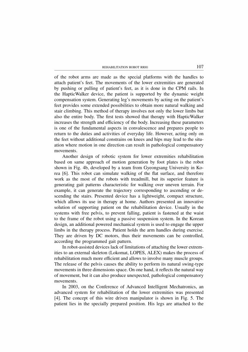
In 2003, on the Conference of Advanced Intelligent Mechatronics, anadvanced system for rehabilitation of the lower extremities was presented[4]. The concept of this wire driven manipulator is shown in Fig. 5. Thepatient lies in the specially prepared position. His legs are attached to the
108 MARCIN KACZMARSKI, GRZEGORZ GRANOSIK
Fig. 5. Wire driven system for lower extremities rehabilitation: concept and the prototype,
reproduced from [4]
adjustable harnesses, which are connected by the wires to electric motorsmounted on an external frame. System of cables and blocks placed aroundthe patient on the frame allows for easily manipulation of patient’s leg withina designated workspace. Increasing the number of drives used in the systemcan produce more complex movements.
2. Construction of the RRH1 robot
Our own rehabilitation robot for lower extremities is presented in Fig. 6.Beside the photograph of the fully functional prototype, there is a schemat-ic drawing showing major components, possible movements (with arrows)and the working space of the robot (dashed line presenting section of thecylinder).
Robot consists of an aluminum chassis and adjustable column located onthe rectangular base. Lightweight construction (about 100 kg), together withtwo standard, and two castor wheels make whole mechanism easy to movefrom one hospital bed to another, even by one person. There is no needto relocate patients to special rehabilitation area; treatment can be startedshortly after accident or can be applied even for unconscious person. Robotcan be locked in place by brakes mounted on wheels (F1) while its heightcan be adjusted for specific bed and patient by the crank (E).
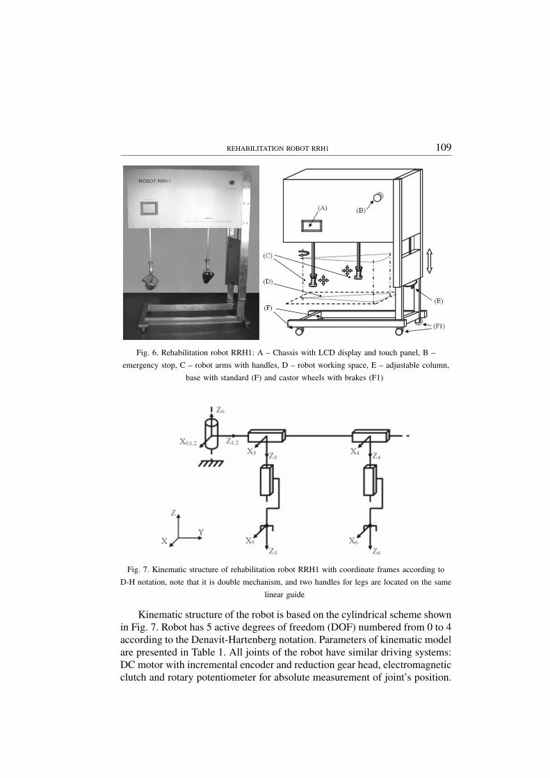
REHABILITATION ROBOT RRH1 109
Fig. 6. Rehabilitation robot RRH1: A – Chassis with LCD display and touch panel, B –
emergency stop, C – robot arms with handles, D – robot working space, E – adjustable column,
base with standard (F) and castor wheels with brakes (F1)
Fig. 7. Kinematic structure of rehabilitation robot RRH1 with coordinate frames according to
D-H notation, note that it is double mechanism, and two handles for legs are located on the same
linear guide
Kinematic structure of the robot is based on the cylindrical scheme shownin Fig. 7. Robot has 5 active degrees of freedom (DOF) numbered from 0 to 4according to the Denavit-Hartenberg notation. Parameters of kinematic modelare presented in Table 1. All joints of the robot have similar driving systems:DC motor with incremental encoder and reduction gear head, electromagneticclutch and rotary potentiometer for absolute measurement of joint’s position.
110 MARCIN KACZMARSKI, GRZEGORZ GRANOSIK
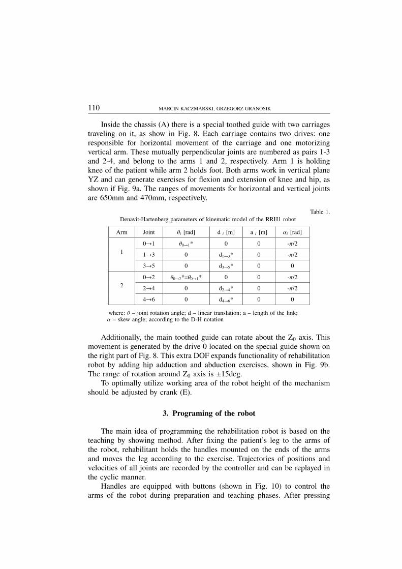
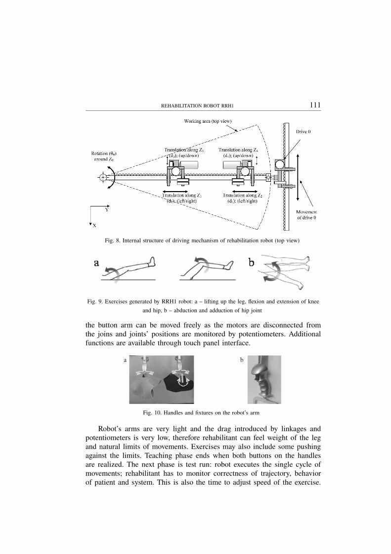
Inside the chassis (A) there is a special toothed guide with two carriagestraveling on it, as show in Fig. 8. Each carriage contains two drives: oneresponsible for horizontal movement of the carriage and one motorizingvertical arm. These mutually perpendicular joints are numbered as pairs 1-3and 2-4, and belong to the arms 1 and 2, respectively. Arm 1 is holdingknee of the patient while arm 2 holds foot. Both arms work in vertical planeYZ and can generate exercises for flexion and extension of knee and hip, asshown if Fig. 9a. The ranges of movements for horizontal and vertical jointsare 650mm and 470mm, respectively.
Table 1.Denavit-Hartenberg parameters of kinematic model of the RRH1 robot
Arm Joint θi [rad] d i [m] a i [m] αi [rad]
10→1 θ0→1* 0 0 -π/2
1→3 0 d1→3* 0 -π/2
3→5 0 d3→5* 0 0
20→2 θ0→2*=θ0→1* 0 0 -π/2
2→4 0 d2→4* 0 -π/2
4→6 0 d4→6* 0 0
where: θ – joint rotation angle; d – linear translation; a – length of the link;α – skew angle; according to the D-H notation
Additionally, the main toothed guide can rotate about the Z0 axis. Thismovement is generated by the drive 0 located on the special guide shown onthe right part of Fig. 8. This extra DOF expands functionality of rehabilitationrobot by adding hip adduction and abduction exercises, shown in Fig. 9b.The range of rotation around Z0 axis is ±15deg.
To optimally utilize working area of the robot height of the mechanismshould be adjusted by crank (E).
3. Programing of the robot
The main idea of programming the rehabilitation robot is based on theteaching by showing method. After fixing the patient’s leg to the arms ofthe robot, rehabilitant holds the handles mounted on the ends of the armsand moves the leg according to the exercise. Trajectories of positions andvelocities of all joints are recorded by the controller and can be replayed inthe cyclic manner.
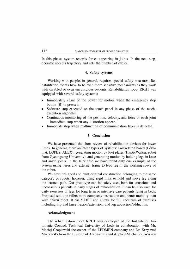
Handles are equipped with buttons (shown in Fig. 10) to control thearms of the robot during preparation and teaching phases. After pressing
REHABILITATION ROBOT RRH1 111
Fig. 8. Internal structure of driving mechanism of rehabilitation robot (top view)
Fig. 9. Exercises generated by RRH1 robot: a – lifting up the leg, flexion and extension of knee
and hip, b – abduction and adduction of hip joint
the button arm can be moved freely as the motors are disconnected fromthe joins and joints’ positions are monitored by potentiometers. Additionalfunctions are available through touch panel interface.
Fig. 10. Handles and fixtures on the robot’s arm
Robot’s arms are very light and the drag introduced by linkages andpotentiometers is very low, therefore rehabilitant can feel weight of the legand natural limits of movements. Exercises may also include some pushingagainst the limits. Teaching phase ends when both buttons on the handlesare realized. The next phase is test run: robot executes the single cycle ofmovements; rehabilitant has to monitor correctness of trajectory, behaviorof patient and system. This is also the time to adjust speed of the exercise.
112 MARCIN KACZMARSKI, GRZEGORZ GRANOSIK
In this phase, system records forces appearing in joints. In the next step,operator accepts trajectory and sets the number of cycles.
4. Safety systems
Working with people, in general, requires special safety measures. Re-habilitation robots have to be even more sensitive mechanisms as they workwith disabled or even unconscious patients. Rehabilitation robot RRH1 wasequipped with several safety systems:
• Immediately cease of the power for motors when the emergency stopbutton (B) is pressed,
• Software stop executed on the touch panel in any phase of the teach-execution algorithm,
• Continuous monitoring of the position, velocity, and force of each joint– immediate stop when any distortion appear,
• Immediate stop when malfunction of communication layer is detected.
5. Conclusion
We have presented the short review of rehabilitation devices for lowerlimbs. In general, there are three types of systems: exoskeleton based (Loko-mat, LOPES, ALEX), generating motion by foot plates (HapticWalker, robotfrom Gyeongsang University), and generating motion by holding legs in kneeand ankle joints. In the later case we have found only one example of thesystem using wires and external frame to lead leg in the working space ofthe robot.
We have designed and built original construction belonging to the samecategory of robots, however, using rigid links to hold and move leg alongthe learned path. Our prototype can be safely used both for conscious andunconscious patients in early stages of rehabilitation. It can be also used fordaily exercises of legs for long term or intensive-care patients lying in beds.Proposed solution offers more compact construction and better mobility thanwire driven robot. It has 5 DOF and allows for full spectrum of exercisesincluding hip and knee flexion/extension, and leg abduction/adduction.
Acknowledgment
The rehabilitation robot RRH1 was developed at the Institute of Au-tomatic Control, Technical University of Lodz in collaboration with Mr.Maciej Czapiewski the owner of the LEDMEN company and Dr. KrzysztofMianowski from the Institute of Aeronautics and Applied Mechanics, Warsaw
REHABILITATION ROBOT RRH1 113
University of Technology who provided valuable consultation on mechanicaldesign.
Manuscript received by Editorial Board, January 18, 2011;final version, February 08, 2011.
REFERENCES
[1] Banala S. K., Kim S. H., Agrawal1 S., Scholz K.: J. P. Robot Assisted Gait Training WithActive Leg Exoskeleton (ALEX). Proc. IEEE/RAS-EMBS Int. Conference on BiomedicalRobotics and Biomechatronics, Scottsdale, AZ, USA, 2008, pp. 653-658.
[2] Colombo G., Joerg M., Schreier R., and Dietz V.: Treadmill training of paraplegic patientsusing a robotic orthosis. Journal of Rehabilitation Research & Development, 37(6), 2000,pp. 693-700.
[3] Ekkelenkamp R., Veneman J., and van der Kooij H.: LOPES: a lower extremity poweredexoskeleton. ICRA 2007, pp. 3132-3133.
[4] Homma K., Fukuda O., Sugawara J., Nagata Y., Usuba M.A.: A Wire-driven Leg Rehabilita-tion System: Development of a 4-DOF Experimental System. Proc. of the 2003 IEEE/ASMEInt. Conference on Advanced Intelligent Mechatronics.
[5] Lunenburger L., Colombo G., Riener R., Dietz V.: Biofeedback in gait training with therobotic orthosis Lokomat. Engineering in Medicine and Biology Society, 2004. 26th AnnualInternational Conference of the IEEE; Vol. 2, pp. 4888-4891.
[6] Novandy B., Yoon J., Manurung A.: Interaction Control of a Programmable Footpad-TypeGait Rehabilitation Robot for Active Walking on Various Terrains. ICORR 2009.
[7] Salter RB.: The Biologic Concept of Continuous Passive Motion of Synovial Joints: The First18 Years of Basic Research and Its Clinical Application, Clinical Orthopaedics and RelatedResearch – Vol. 242, 1989, pp. 12-25.
[8] Schmidt H., Volkmar M., Werner C., Helmich I., Piorko F., Kruger J., Hesse S.: Muscleactivation patterns of healthy subjects during floor walking and stair climbing on an end-effector-based gait rehabilitation robot. ICORR, The Netherlands, 2007.
[9] Vallery H., Ekkelenkamp R., van der Kooij H., and Buss M.: Passive and accurate torquecontrol of series elastic actuators. IROS 2007, pp. 3534-3538.
[10] Veneman J.F., Ekkelenkamp R., Kruidhof R., van der Helm F.C.T., and van der Kooij H.:Design of a series elastic- and Bowden cable-based actuation system for use as torque-actuatorin exoskeleton-type training. ICORR 2005, Chicago, pp. 496-499.
Robot rehabilitacyjny RRH1
S t r e s z c z e n i e
Artykuł prezentuje prototyp robota do rehabilitacji kończyn dolnych. Robot zbudowany jestw oparciu o cylindryczny układ kinematyczny o dwóch sztywnych ramionach. Posiada 5 aktywnychstopni swobody i przeznaczony jest do odtwarzania zadanej przez fizykoterapeutę trajektorii ruchu.Robot posiada możliwość odtwarzania ćwiczeń zgięcia, wyprostu w stawie kolanowym i biodrowymoraz przywodzenia i odwodzenia nogi. Zastosowany w robocie system zabezpieczeń, zawierającydetekcję nadmiernego oddziaływania kończyny dolnej na ramiona robota, pozwala na bezpiecznąpracę z pacjentami.