Embed Size (px)
Citation preview
1
Design and analysis of a visible-light-communicationenhanced WiFi system
Sihua Shao, Abdallah Khreishah, Moussa Ayyash, Michael B. Rahaim, Hany Elgala,Volker Jungnickel, Dominic Schulz, Thomas D.C. Little
Abstract—Visible light communication (VLC) has wide un-licensed bandwidth, enables communication in radio fre-quency (RF) sensitive environments, realizes energy-efficient datatransmission, and has the potential to boost the capacity ofwireless access networks through spatial reuse. On the otherhand, WiFi provides more coverage than VLC and does not sufferfrom the likelihood of blockage due to the line-of-sight (LOS)requirement of VLC. In order to take the advantages of bothWiFi and VLC, we propose and implement two heterogeneoussystems with Internet access. One is the hybrid WiFi-VLCsystem, utilizing unidirectional VLC channel as downlink andreserving the WiFi back-channel as uplink. The asymmetricsolution resolves the optical uplink challenges and benefits fromthe full-duplex communication based on VLC. To further enhancethe robustness and increase throughput, the other system ispresented, in which we aggregate WiFi and VLC in parallel byleveraging the bonding technique in Linux operating system. Wealso theoretically prove the superiority of the aggregated systemin terms of average system delay. Online experiment resultsreveal that the hybrid system outperforms the conventional WiFifor the crowded environments in terms of throughput and webpage loading time; and also demonstrate the further improvedperformance of the aggregated system when considering theblocking duration and the distance between access point anduser device.
Keywords—Hybrid system, heterogeneous network (HetNet),WiFi, visible light communications (VLC), link aggregation.
I. INTRODUCTION
The continuous growth in the adoption of mobile devicesincluding smart phones, tablets, laptops, and now devices onthe “Internet of Things” is driving an insatiable demand fordata access to wireless networks. According to the CiscoVisual Networking Index [1], traffic from wireless andmobile devices will exceed traffic from wired devices by2019. By 2019, wired devices will account for 33 percentof IP traffic, while Wi-Fi and mobile devices will accountfor 66 percent of IP traffic. Although wireless providersare deploying additional access infrastructure by means ofnew cells and WiFi end points, the limitation is becoming
Sihua Shao and Abdallah Khreishah are with the Department of Electri-cal and Computer Engineering, New Jersey Institute of Technology, email:[email protected], [email protected]
Moussa Ayyash is with the Department of Information Studies, ChicagoState University, email: [email protected]
Michael B. Rahaim, Hany Elgala, Thomas D.C. Little are with the De-partment of Electrical and Computer Engineering, Boston University, email:[email protected], [email protected], [email protected]
Volker Jungnickel and Dominic Schulzi are with Fraunhofer-HHI, email:[email protected], [email protected]
overuse of existing RF spectrum. This manifests as contentionand interference, and results in an increase in latency and adecrease in network throughput – a “spectrum crunch” [2].To alleviate this problem, new approaches to realize largerpotential capacity at the wireless link are needed and opticaltechnologies including visible light communication (VLC) areexcellent candidates.
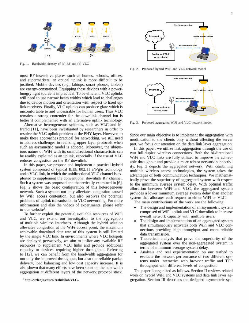
VLC technology provided with LED devices is characterizedby high area spectral efficiency, unlicensed wide bandwidth,high security and dual-use nature [3]. For example, Fig. 1shows how VLC can reuse spectrum efficiently in a smallarea. Case a) shows a WiFi channel in which three users sharea 30Mb/s bandwidth, compared to Case b), a VLC-enabledenvironment, in which three users utilize individual 10Mb/sVLC channels. Although the total bandwidth allocated to thethree users are the same in two cases, the outcome aggregatedthroughput of Case b) could be better than that of Case a), dueto the contention effect on RF channel as we will see later.It is worth noticing that the gain of VLC channel highlydepends on the strict alignment between VLC transceivers.In contrast to the omnidirectional WiFi channel, themobility of users will lead to severe degradation of VLCchannel gain. Nevertheless, in this paper, the users’ locationare assumed to be fixed and the mobility issue is out ofthe scope of this paper. As a complementary approach to theexisting wireless RF solutions, VLC is poised to overcomethe crowded radio spectrum in highly-localized systems andbecome a promising broadband wireless access candidate toresolve the “spectrum crunch”.
LED-based indoor VLC has attracted great attention in re-cent years due to its innate physical properties including energyefficiency and lower operational cost compared to conventionalincandescent and fluorescent lighting [4]. Current researchon VLC focuses mainly on physical (PHY) layer techniquessuch as dimming support, flicker mitigation, and advancedmodulation schemes [5]. These efforts seek to achieve thepossible highest data rates. However, higher-level networkingchallenges must be addressed to enable interoperability in anypractical network deployment [6]–[9].
Under a dual-use model, VLC is realized by overheadlighting – lights serve to provide lighting and also dataaccess. However, providing an uplink in such a system ischallenging due to potential energy limitations of mobiledevices (that do not need to produce light for illumination)and potential glare from the produced light. In RF-sensitiveand high-security applications, an optical uplink is possiblewith relatively high transmission speed [10]. However, in
2
Fig. 1. Bandwidth density of (a) RF and (b) VLC
most RF-insensitive places such as homes, schools, offices,and supermarkets, an optical uplink is more difficult to bejustified. Mobile devices (e.g., labtops, smart phones, tablets)are energy-constrained. Equipping these devices with a power-hungry light source is impractical. To be efficient, VLC uplinkswill need to use narrow beam widths which lead to challengesdue to device motion and orientation with respect to fixed up-link receivers. Finally, VLC uplinks can produce glare which isuncomfortable to and undesirable for human users. Thus VLCremains a strong contender for the downlink channel but isbetter if complemented with an alternative uplink technology.
Alternative heterogeneous schemes, such as VLC and in-frared [11], have been investigated by researchers in order toresolve the VLC uplink problem at the PHY layer. However, tomake these approaches practical for networking, we still needto address challenges in realizing upper layer protocols whensuch an asymmetric model is adopted. Moreover, the ubiqui-tous nature of WiFi with its omnidirectional characteristic canbe readily exploited as an uplink, especially if the use of VLCreduces congestion on the RF downlink.
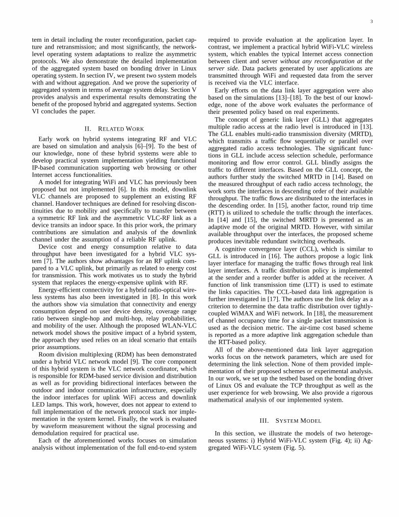
In this paper, we propose and implement a practical hybridsystem comprised of typical IEEE 802.11 a/b/g/n technologyand a VLC link, in which the unidirectional VLC channel is ex-ploited to supplement the conventional downlink RF channel.Such a system was proposed and theoretically examined in [6].Fig. 2 shows the basic configuration of this heterogeneousnetwork. Such a system not only alleviates congestion causedby WiFi access contention, but also resolves the potentialproblems of uplink transmission in VLC networking. For moreinformation and also the videos of experiments, please referto our website1.
To further exploit the potential available resources of WiFiand VLC, we extend our investigation to the aggregationof multiple wireless interfaces. Although the hybrid solutionalleviates congestion at the WiFi access point, the maximumachievable download data rate of this system is still limitedby the single VLC link. In environments where VLC hotspotsare deployed pervasively, we aim to utilize any available RFresources to supplement VLC links and provide additionalcapacity to devices requiring higher throughput. Referringto [12], we can benefit from the bandwidth aggregation fornot only the improved throughput, but also the reliable packetdelivery, load balancing and low cost capacity increase. It isalso shown that many efforts have been spent on the bandwidthaggregation at different layers of the network protocol stack.
1http://web.njit.edu/%7eabdallah/VLC/.
Fig. 2. Proposed hybrid WiFi and VLC network model
Fig. 3. Proposed aggregated WiFi and VLC network model
Since our main objective is to implement the aggregation withmodification to the clients only without affecting the serverpart, we focus our attention on the data link layer aggregation.
In this paper, we utilize link aggregation through the use oftwo full-duplex wireless connections. Both the bi-directionalWiFi and VLC links are fully utilized to improve the achiev-able throughput and provide a more robust network connectiv-ity. Fig. 3 depicts the aggregated network. With combiningmultiple wireless access technologies, the system takes theadvantages of both communication techniques. We mathemat-ically prove the superiority of aggregated system with respectto the minimum average system delay. With optimal trafficallocation between WiFi and VLC, the aggregated systemprovides a lower minimum average system delay than anothersystem that allocates each request to either WiFi or VLC.
The main contributions of the work are the following:• The design and implementation of an asymmetric system
comprised of WiFi uplink and VLC downlink to increaseoverall network capacity with multiple users.
• The design and implementation of an aggregated systemthat simultaneously activates both WiFi and VLC con-nections providing high throughput and more reliabledata transmission.
• Theoretical analysis that prove the superiority of theaggregated system over the non-aggregated system interms of minimum average system delay.
• Analysis and real experimentation on our testbed toevaluate the network performance of two different sys-tems under interactive web browser traffic and TCPthroughput with different levels of congestion.
The paper is organized as follows. Section II reviews relatedwork on hybrid WiFi and VLC systems and data link layer ag-gregation. Section III describes the designed asymmetric sys-
3
tem in detail including the router reconfiguration, packet cap-ture and retransmission; and most significantly, the network-level operating system adaptations to realize the asymmetricprotocols. We also demonstrate the detailed implementationof the aggregated system based on bonding driver in Linuxoperating system. In section IV, we present two system modelswith and without aggregation. And we prove the superiority ofaggregated system in terms of average system delay. Section Vprovides analysis and experimental results demonstrating thebenefit of the proposed hybrid and aggregated systems. SectionVI concludes the paper.
II. RELATED WORK
Early work on hybrid systems integrating RF and VLCare based on simulation and analysis [6]–[9]. To the best ofour knowledge, none of these hybrid systems were able todevelop practical system implementation yielding functionalIP-based communication supporting web browsing or otherInternet access functionalities.
A model for integrating WiFi and VLC has previously beenproposed but not implemented [6]. In this model, downlinkVLC channels are proposed to supplement an existing RFchannel. Handover techniques are defined for resolving discon-tinuities due to mobility and specifically to transfer betweena symmetric RF link and the asymmetric VLC-RF link as adevice transits an indoor space. In this prior work, the primarycontributions are simulation and analysis of the downlinkchannel under the assumption of a reliable RF uplink.
Device cost and energy consumption relative to datathroughput have been investigated for a hybrid VLC sys-tem [7]. The authors show advantages for an RF uplink com-pared to a VLC uplink, but primarily as related to energy costfor transmission. This work motivates us to study the hybridsystem that replaces the energy-expensive uplink with RF.
Energy-efficient connectivity for a hybrid radio-optical wire-less systems has also been investigated in [8]. In this workthe authors show via simulation that connectivity and energyconsumption depend on user device density, coverage rangeratio between single-hop and multi-hop, relay probabilities,and mobility of the user. Although the proposed WLAN-VLCnetwork model shows the positive impact of a hybrid system,the approach they used relies on an ideal scenario that entailsprior assumptions.
Room division multiplexing (RDM) has been demonstratedunder a hybrid VLC network model [9]. The core componentof this hybrid system is the VLC network coordinator, whichis responsible for RDM-based service division and distributionas well as for providing bidirectional interfaces between theoutdoor and indoor communication infrastructure, especiallythe indoor interfaces for uplink WiFi access and downlinkLED lamps. This work, however, does not appear to extend tofull implementation of the network protocol stack nor imple-mentation in the system kernel. Finally, the work is evaluatedby waveform measurement without the signal processing anddemodulation required for practical use.
Each of the aforementioned works focuses on simulationanalysis without implementation of the full end-to-end system
required to provide evaluation at the application layer. Incontrast, we implement a practical hybrid WiFi-VLC wirelesssystem, which enables the typical Internet access connectionbetween client and server without any reconfiguration at theserver side. Data packets generated by user applications aretransmitted through WiFi and requested data from the serveris received via the VLC interface.
Early efforts on the data link layer aggregation were alsobased on the simulations [13]–[18]. To the best of our knowl-edge, none of the above work evaluates the performance oftheir presented policy based on real experiments.
The concept of generic link layer (GLL) that aggregatesmultiple radio access at the radio level is introduced in [13].The GLL enables multi-radio transmission diversity (MRTD),which transmits a traffic flow sequentially or parallel overaggregated radio access technologies. The significant func-tions in GLL include access selection schedule, performancemonitoring and flow error control. GLL blindly assigns thetraffic to different interfaces. Based on the GLL concept, theauthors further study the switched MRTD in [14]. Based onthe measured throughput of each radio access technology, thework sorts the interfaces in descending order of their availablethroughput. The traffic flows are distributed to the interfaces inthe descending order. In [15], another factor, round trip time(RTT) is utilized to schedule the traffic through the interfaces.In [14] and [15], the switched MRTD is presented as anadaptive mode of the original MRTD. However, with similaravailable throughput over the interfaces, the proposed schemeproduces inevitable redundant switching overheads.
A cognitive convergence layer (CCL), which is similar toGLL is introduced in [16]. The authors propose a logic linklayer interface for managing the traffic flows through real linklayer interfaces. A traffic distribution policy is implementedat the sender and a reorder buffer is added at the receiver. Afunction of link transmission time (LTT) is used to estimatethe links capacities. The CCL-based data link aggregation isfurther investigated in [17]. The authors use the link delay as acriterion to determine the data traffic distribution over tightly-coupled WiMAX and WiFi network. In [18], the measurementof channel occupancy time for a single packet transmission isused as the decision metric. The air-time cost based schemeis reported as a more adaptive link aggregation schedule thanthe RTT-based policy.
All of the above-mentioned data link layer aggregationworks focus on the network parameters, which are used fordetermining the link selection. None of them provided imple-mentation of their proposed schemes or experimental analysis.In our work, we set up the testbed based on the bonding driverof Linux OS and evaluate the TCP throughput as well as theuser experience for web browsing. We also provide a rigorousmathematical analysis of our implemented system.
III. SYSTEM MODEL
In this section, we illustrate the models of two heteroge-neous systems: i) Hybrid WiFi-VLC system (Fig. 4); ii) Ag-gregated WiFi-VLC system (Fig. 5).

4
TABLE I. AN EXAMPLE OF STATIC ROUTING TABLE
Dst IP Subnet Mask Next hop Metric192.168.1.100 255.255.255.255 192.168.1.200 2
A. Hybrid System
Challenges: The primary challenges of designing an asym-metric system are as follows:
1) Typically, uplink and downlink data streams based onWiFi connection between the client and the server flow throughthe same routing path. In order to redirect the data flowdownloaded from the server to the client to the VLC hotspot,an intermediate coordinator is needed to break the conventionaldownlink data delivery and forward the data packets to theVLC hotspot. However, this process may generate inevitableredundancy due to the need of extra devices to perform dataredirection. In Fig. 4, we aim to assign the infrastructural routeras the redirecting node, forwarding downlink traffic to PC I andsimultaneously providing PC II with an uplink wireless access.
2) A typical small office home office (SOHO) wireless routerhas one wide area network (WAN) port and multiple localnetwork (LAN) Ethernet ports. Terminals connected to therouter through either wired or wireless links belong to thesame sub-network. This router serves as an edge router with agateway IP address. Intuitively, we might be able to activate therouting function on PC I in Fig. 4, in order to directly forwardthe data packets from the router to PC II. However, due tothe OS kernel built-redirecting function, the simple forwardingmethod based on the routing function may not be useful. Sincethe destination IP address of the data packets that arrive at thenetwork interface card (NIC) A-1 is actually the IP address ofNIC B-1, the packets will be redirected back to PC II throughthe router instead of the VLC link, if the forwarding functionof PC I is activated.
3) In a typical TCP connection, the client initiates a three-phase handshake process with the server. According to the OSImodel, the client first generates a SYN data segment at theapplication layer. After that, the data segment is encapsulatedwith IP headers at the network layer before being sent outthrough the NIC. Since the client starts listening to the socketwith the same TCP port and IP address as that used duringencapsulation, the following problem occurs. If the packetsfrom the server are received from a different NIC with differentsocket information, they may not be selected by the applicationthat initiated the TCP connection. In Fig. 4, the requests aretransmitted through NIC B-1 while the responses are receivedfrom NIC B-2. The above problem is encountered in theasymmetric system in Fig. 4.
System Design: Fig. 4 demonstrates the hybrid systemmodel for indoor Internet access. The system consists of adownlink VLC channel and an uplink WiFi channel. To resolvethe challenges mentioned earlier, three procedures (each one ofthese procedures corresponds to one of the above challenges)need to be performed as follows:
1) To address the problem mentioned in the first challenge,a static routing table is enabled at the router. Rather thandynamically forwarding IP packets as normal, the router fol-lows a manually-configured routing entry with three items:
Fig. 4. Hybrid system architecture
Algorithm 1 Pseudo code of socket programInitialization:
Define BufferSize MTU;Set socket s for frames capture;Set socket d for frames retransmission;Bind socket s to NIC A-1;Bind socket d to NIC A-2;
Iteration:1: while 1 do2: Receive frames from socket s and store into buffer
msg[BufferSize];3: if frame length > MTU then4: Continue;5: end if6: if frame desitination IP addr = IP B-1 then7: Change dest MAC addr to MAC B-2;8: Change src MAC addr to MAC A-2;9: Change dest IP addr to IP B-2;
10: Compute IP checksum;11: Compute TCP checksum;12: Compute UDP checksum;13: Send modified frames to socket d;14: end if15: end while
i) destination IP address, ii) subnet mask, and iii) next-hoprouter IP address. Table 1 shows an example of routing IPtraffic destined for the 192.168.1.100/24 via the next-hoprouter with the IPv4 address of 192.168.1.200/24. In theproposed hybrid system, one active static routing rule redirectsIP packets destined for NIC B-1 to NIC A-1 instead.
2) After successfully arriving at the relay node (PC I), serverIP packets need to be further forwarded to the client throughNIC A-2. In the Linux OS, the IP packet forwarding functionis enabled by changing the value of ip forward under the path“/proc/sys/net/ipv4/ip forward” from 0 to 1. As mentioned inthe challenge (2) earlier, if we activate the forwarding functionon PC I, the arrived IP packets will be redirected back to PC IIthrough NIC A-1 instead of NIC A-2. Therefore, we mustset the value of ip forward to 0. Rather than relying on theforwarding function, we utilize the socket programming basedon SOCK PACKET type [19].
The SOCK PACKET mechanism in Linux is used totake complete control of the Ethernet interfaces. Due to thecapability of capturing frames from the data link layer and

5
placing a pointer which points to the first byte of each frame(the first byte of MAC header), SOCK PACKET is suitablefor MAC frames capturing and retransmission. Algorithm 1represents the relaying functionality. In the algorithm, we firstdefine the buffer size according to the maximum transmissionunit (MTU) which is a default value in the router. Then twosockets of the SOCK PACKET type are created and boundto NIC A-1 and NIC A-2. After the initialization phase ofkey parameters, the iteration phase, which includes receiving,processing and retransmission, is started. To avoid the alertof no buffer space available for the sending function, thereceived frame length needs to be checked. If the length islarger than the defined MTU, the frame must be discarded.Also, the destination IP address of the captured frames forefficient relaying is checked. If it is the same as the IPaddress of NIC B-1, we manually modify packet’s MACand destination IP address. To realize the Internet access, thechecksums of IP, TCP and UDP need to be recomputed beforesending the packets to the client. This is because the checksumcomputation includes the destination IP address.
3) As it is mentioned in challenge (3) earlier, the applicationthat initiates the TCP connection to the server will listen to thesocket with the IP address of NIC B-1 but not NIC B-2. TheOS kernel will not do any action on the packets although theyare not filtered by the NIC. A possible solution is changingthe destination IP of the packets to the IP address of NIC B-1. However, due to the fact that the destination IP address ofthe packets is not that of the port they are received from, thepackets should be forwarded based on the routing table. Toovercome this difficulty, an approach called “operating systemspoofing” is proposed.
Operating System Spoofing: The basic idea of this approachis to manually make the OS listen to NIC B-2 while trans-mitting out the packets through NIC B-1. Assume that theIP addresses of NIC B-2 is 192.168.2.100/24 and the defaultgateway of PC II is 192.168.1.1/24. The default gateway isdeleted and a new one within the subnet 192.168.2.0/24 (e.g.192.168.2.1/24) is added. In addition, an entry in the ARPtable on PC II (e.g. arp -s 192.168.2.1 ab:ab:ab:ab:ab:ab) isadded. When these two steps are completed, PC II will believethat there is a next-hop gateway connected to NIC B-2 eventhough this gateway does not exist. With the ARP spoofing,all packets generated at the application layer on PC II areforwarded to NIC B-2 and stop there because of the physicallayer blocking. The most significant point at this moment isthat the applications are listening to the socket with the IPaddress of NIC B-2.
After the configuration of the routing and ARP tables, asocket program, that implements packets copying, headersmodification and retransmission, is run. Similar to the programrun on PC I, the socket of type SOCK PACKET is used tocapture the packets flowing through the device driver layer ofNIC B-2. With the returned pointer, the source IP and MACaddresses of the copied packets to the IP and MAC addressesof NIC A-1 are altered. Also, we change the destinationMAC address to router’s LAN MAC address. The checksumsof IP, TCP and UDP need to be recomputed. After all themodifications of the IP and MAC headers are completed, the
Fig. 5. Aggregated system architecture
Fig. 6. Flow of MAC and IP headers of packets between server and client,a) downlink flow and b) uplink flow
packets are sent to the router through NIC B-1. From therouter’s point of view, the client’s IP is the IP address of NICB-1. However, from the client’s point of view, it connects tothe Internet with the IP address of NIC B-2. Fig. 6 reveals thevariation of IP and MAC headers.
Note that, compared to the previously published work [20],the achievable network throughput of the proposed hybridsystem has been enhanced [21]. For the packets captured onPC II, a selective condition before sending them to the routeris added. Only the packets with a source IP same as the IPaddress of NIC B-2 are processed by the program. Since thecapture function returns the packets not only in the transmittingbuffer of NIC B-2 but also in the receiving buffer, the addedcondition saves half of the redundant processing time in theunmodified program.
B. Aggregated System
Fig. 5 demonstrates the link aggregation system modelincluding the full-duplex WiFi and VLC connections. Sincethe bonding driver provided by Linux operating system isonly capable of aggregating Ethernet interfaces, both NICC-1 and NIC C-2 of PC I (client) are Ethernet cards. Thewireless Router I working in client mode, is connected to PCI through Ethernet cable and connected to Router II through bi-directional WiFi link. The other network connection betweenthe PC I and the Router II is a bi-directional VLC link, which isestablished by two VLC transceivers. The bi-directional VLClink will be described in section V. The two NICs on PC Iare in the same subnet and the IP address of Router II LAN

6
is used as the IP address of the gateway of PC I, when theaggregation configuration is not enabled. On the right side, PCII (server) is connected to the WAN port of Router II.
To implement the data link layer aggregation, we utilizethe Linux Ethernet bond driver [22]. The driver providesa method to aggregate multiple Ethernet interfaces into asingle logical “bond” interface. The behavior of the artificialinterface depends on the selected mode. There are seven modesin bonding configuration: 0) Balance-rr; 1) Active-backup;2) Balance-xor; 3) Broadcast; 4) 802.3ad; 5) Balance-tlb; 6)Balance-alb. Modes 0, 2 and 4 require extra switch support,which conflict with our objective of not having extra devices.Under Mode 1, only one slave in the bond is active. The otherslave becomes active if and only if the active slave fails. Thus,the maximum throughput that can be achieved in this mode cannot exceed the highest one of the slaves. In Mode 3, the samepackets are sent through all slave interfaces, in order to providefault tolerance. Therefore, only Mode 5 and Mode 6 are leftto choose from. For the goal of achieving higher aggregatedthroughput without any modification to the server side or evento the next hop of the client, Mode 6 is the best option.
Mode 6 (adaptive load balancing) contains Mode 5 (adaptivetransmit load balancing). Also, Mode 6 integrates the receiveload balancing for the IPv4 traffic and does not require anyswitch support. Load balancing at the receiver is achieved byARP negotiation. The bond driver intercepts the ARP responsesent from the host and changes the source MAC address to theunique MAC address of one of the slaves. It enables the peersto use a different MAC address for communication. Typically,all the slave ports will receive the broadcast ARP requestsfrom the router. The bond driver module intercepts all the ARPresponses sent from the client, and computes the correspondingport that the client expects to receive data from. Then thedriver modifies the source MAC address of the ARP responseto the MAC address of the corresponding port. The destinationMAC address is kept the same as the MAC address of therouter LAN. Note that each port can send the ARP responsenot only with its own MAC address but also with the MACaddress of the other slave port. The received data traffic can beload balanced in either way. When the client sends the ARPrequest, bonding driver copies and saves the IP informationof the router. When the ARP reply from the router arrives,the bond driver extracts the MAC address of the router andsends an ARP response to one of the slave ports (this processis the same as the received load balancing process mentionedabove). One potential problem in ARP negotiation is that whenthe client sends out the ARP request, it uses the MAC addressof the logic bonding interface. Thus, after the router learnsthis MAC address, the downlink traffic from the server flowsthrough the corresponding slave port which may not be theintended one. This problem can be addressed by sending theupdated ARP response. The client sends the ARP responsesto all slave ports and each response contains the unique MACaddress of each slave port. Thus, the downlink traffic fromthe server are redistributed. The receive load [22] is allocatedorderly from the slave with widest bandwidth.
In Fig. 5, when Router II broadcasts ARP request to PC I,PC I typically sends back an ARP response with the bonding
MAC address and the bonding IP address. However, underadaptive load balancing mode, the bonding driver interceptsthe APR response and changes the source MAC address tothat of one of the slaves (e.g. NIC C-1). Thus, when the routerreceives the ARP response, it refreshes its ARP cache with anew entry (Bond IP: NIC C-1 MAC). To increase the totalbandwidth of the client, PC I sends back the ARP responsewith the NIC C-2 MAC address when the capacity of NICC-1 is exhausted. After receiving the new ARP response, therouter updates its ARP cache (Bond IP: NIC C-2 MAC).
C. Analysis
“Spectrum crunch” [2] is a challenging problem in WiFinetworks. Due to the limited bandwidth, although the effi-ciency of the spectrum utilization has been highly improved,the degradation of network throughput caused by the growingnumber of WiFi users and other devices operating in the2.4 and 5 GHz bands is still inevitable. Also, the networkdelay could be much larger when the number of users in thesame WiFi access point increases. Because of the CSMA/CAmechanism defined in 802.11 standards [23], the average back-off time is unavoidably increased when there exists moremobile users located in the same WiFi coverage. To cir-cumvent these unexpected user experiences, the hybrid WiFi-VLC system is presented. Although the uplink WiFi may bein contention with other WiFi users, the downlink VLC isan independent data communication channel from the WiFichannels. In our daily life, downloading happens much morefrequently than uploading; hence having an undisturbed VLCdownload channel may provide a satisfactory Internet surfingexperience. Regarding the increasing demand for downlinkbandwidth, the hybrid VLC user does not need to competewith other WiFi users for the RF spectrum. Therefore, thenetwork delay will be reduced.
In some specific scenarios where uplink VLC is allow-able, aggregating both bi-directional WiFi and VLC links canprovide more available bandwidth. Taking the shortages ofVLC into account, the aggregated system is more robust thanthe hybrid one. As the distance between the front-ends ofWiFi and VLC is increasing or the channel blocking durationis increasing, the performance of VLC channel may dropquickly. However, these two factors are not influential inWiFi communication when considering the short distance forindoor links. Aggregation may not only achieve higher averagethroughput, but maintain advantages of both WiFi and VLC.
IV. SYSTEM DELAY ANALYSIS
In this section, we show the benefits of the aggregatedsystem theoretically. This is done by comparing the delayperformance of this system to another system that assigns eachrequest to either the VLC channel or the WiFi channel. In theaggregated system, any request is divided into two and theresulting two pieces of the request are forwarded to the WiFiand VLC channels, respectively. We also derive the optimalrequests splitting ratio. In the second system, the request isforwarded to either WiFi or VLC channel. The optimal ratiosof the requests to be forwarded to either WiFi or VLC are

7
Fig. 7. Queuing model representingthe aggregated system model
Fig. 8. Queuing model representingthe Non-aggregated system model
also derived for this system. The major result we get in thissection is that the minimum average delay of the aggregatedsystem is always lower than that of non-aggregated system.We realize that the effect of lower delay will be less drasticas the number of VLC hotspots increases. The objective ofthis theoretical analysis is to verify the superiority of theaggregated WiFi-VLC system over the non-aggregated onewith respect to the optimal system delay and evaluate thedegree of this superiority with different traffic patterns.
In our system model, we have one WiFi AP and oneVLC hotspot. Requests arrive to the system according to aPoisson process with rate λ. The size of the request followsan exponential distribution with an average value of μ. Thebandwidth of the WiFi channel and the VLC channel are B1
and B2, respectively. We assume that B1 < B2.
A. Aggregated System Analysis
Let α represent the percentage of the request’s size that issent to the WiFi channel. Based on the above discussion, theaggregated system can be represented by the queuing systemin Fig. 7. Since one request is split into two and forwarded toeach channel, the average requests arrival rates for WiFi andVLC are both λ. Since μ represents the average request size,the average serving rates of WiFi and VLC are B1/αμ andB2/(1− α)μ, respectively.
Lemma 1: In the aggregated system model, the minimumaverage system delay is μ
B1+B2−λμ .Proof: The optimization problem is written as follows:
Objective: min E[max(DWiFi, DV LC)] (1)s.t. 0 ≤ α ≤ 1
λ < B1/αμ
λ < B2/(1− α)μ
B1 < B2
Based on M/M/1 queuing model, the average system delayof WiFi and VLC are exponentially distributed with averagerates DWiFi = 1
[B1/αμ]−λ and DV LC = 1[B2/(1−α)μ]−λ ,
respectively. In the aggregated system model, when one requestcomes, it is separated into two. One part of the request issent to the WiFi channel and the other part is sent to theVLC channel at exactly the same time. Also the sizes of thetwo parts of the request are dependent. Therefore, minimizingthe maximum delay of WiFi and VLC, given in equation(1), is equivalent to DWiFi = DV LC . According to theabove discussion, we can conclude that the optimal α and theminimum average system delay are
αopt agg =B1
B1 +B2
Dmin agg =μ
B1 +B2 − λμ
B. Non-aggregated System Analysis
Let α denote the percentage of the requests that is sent tothe WiFi channel. The non-aggregated system is equivalent tothe queuing system in Fig. 8. We assume that the requestsare randomly allocated to each channel. Hence, the requestsarrival for each queue is still Poisson process. The averagerequests arrival rates in WiFi and VLC are αλ and (1− α)λ,respectively. Since there is no request splitting in this model,the average serving rates of WiFi and VLC are B1/μ andB2/μ, respectively.
Lemma 2: In the non-aggregated system model, the mini-mum average system delay is
Dmin non agg =
{2λμ−B2(1−
√β)2
λ[B2(β+1)−λμ] , if B2
λμ (1−√β) < 1
μB2−λμ , otherwise
Proof: The optimization problem can be presented asfollows:
Objective: min αDWiFi + (1− α)DV LC
s.t. 0 ≤ α ≤ 1
αλ < B1/μ (2)(1− α)λ < B2/μ (3)B1 < B2
In order to find the candidate minimum point, we describethe average delay of non-aggregated system as a function
D(α) = αDWiFi + (1− α)DV LC
=α
B1/μ− αλ+
1− α
B2/μ− (1− α)λ
We can observe that D(α) is continuous in (1 −B2/λμ,B1/λμ). Based on constraints (2) and (3), we have1− B2/λμ < 0 and B1/λμ > 1. Hence, D(α) is continuousin [0,1]. To find the extreme points, the derivative of D(α) iscalculated
D′(α) =aα2 + bα+ c
f2(α),
where
a = λ2(B1 −B2),
b = 2λB1(−λμ+ 2B2)/μ,
c = B1(B22 − 2λμB2 + λ2μ2 −B1B2)/μ
2,
f(α) =√μ(−λα+B1/μ)(λα+B2/μ− λ).
Here, f2(α) �= 0 when α is in [0,1]. Since a < 0 andb2 − 4ac > 0, D′(α) has two zero points α1 and α2. Weobserve that
8
0 50 1000.4
0.6
0.8
1
1.2
1.4
The bandwidth of WiFi (Mbps)
(a)
Min
imum
ave
rage
syst
em d
elay
s (s)
60 70 80 90 1000.5
1
1.5
2
2.5
The bandwidth of VLC (Mbps)
(b)M
inim
um a
vera
ge sy
stem
del
ays (
s)
0 20 40 60 800
0.5
1
1.5
The request size (Mb)
(c)
Min
imum
ave
rage
syst
em d
elay
s (s)
0 0.1 0.2 0.3 0.40.4
0.6
0.8
1
1.2
1.4
The request arrival rate (per second)
(d)
Min
imum
ave
rage
syst
em d
elay
s (s)
aggregated system non−aggregated system
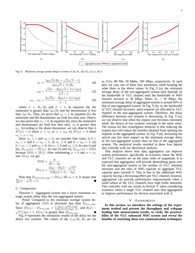
Fig. 9. Minimum average system delays in terms of (a) B1; (b) B2; (c) μ; (d) λ
α1 =λμ
√β/B2 +
√β(
√β − 1)
λμ(√β + 1)/B2
(4)
α2 =
√β[1−B2(
√β + 1)/(λμ)]√
β − 1(5)
α2 − α1 =2√β[1−B2(β + 1)/(λμ)]
β − 1(6)
where β = B1/B2 and β < 1. In equation (4), thenumerator is greater than λμ/B2 and the denominator is lessthan λμ/B2. Thus, we prove that α1 < 1. In equation (5), thenumerator and the denominator are both less than zero. Hence,we also prove that α2 > 0. In equation (6), since the numeratorand denominator are both less than zero, α2 is greater thanα1. According to the above discussion, we can observe that i)D′(α) < 0 when α < α1 or α > α2; ii) D′(α) > 0 whenα1 < α < α2.
Since α1 < 1 and α2 > 0, we consider four cases: i) 0 <α1 < 1 and 0 < α2 < 1; ii) α1 ≤ 0 and 0 < α2 < 1; iii)0 < α1 < 1 and α2 ≤ 0; iv) α1 ≤ 0 and α2 ≤ 0. In case i) andiii), Dmin(α) = D(α1). In case ii) and iv), Dmin(α) = D(0)because D(0) < D(1). After substituting α = 0 and α = α1
into D(α), we get
D(0) =μ
B2 − λμ
D(α1) =2λμ−B2(1−
√β)2
λ[B2(β + 1)− λμ]
Note that Dmin non agg = D(α1) iff α1 > 0. It means thatB2
λμ (1−√β) < 1.
C. Comparison
Theorem 1: Aggregated system has a lower minimum av-erage system delay than the non-aggregated system.
Proof: Compared to the minimum average system de-lay of aggregated, D(0) is obviously less than Dmin agg .Since D(α1) − Dmin agg = 1−B2(1−
√β)2/(λμ)
λ[B2(β+1)/(λμ)−1] , and B2(1 −√β/(λμ) < 1, D(α1) is greater than Dmin agg.Fig. 9 represents the simulation results of the delay for the
above two systems. The values of the λ, μ,B1, B2 are set
as 0.5/s, 80 Mb, 50 Mpbs, 100 Mbps, respectively. In eachplot, we vary one of these four parameters while keeping theother three as the above values. In Fig. 9 (a), the minimumaverage delay of the non-aggregated system only depends onthe bandwidth of VLC channel until the bandwidth of WiFichannel increase to 36 Mbps. When B1 = 50 Mbps, theminimum average delay of aggregated system is around 50% ofthat of non-aggregated system. In Fig. 9 (b), as the bandwidthof VLC channel increases, more requests are allocated to VLCchannel in the non-aggregated system. Therefore, the delaydifference between two systems is decreasing. In Fig. 9 (c),we can observe that when the request size becomes extremelysmall, the delays of two systems converge to the same value.The reason for this convergence behavior is that reducing therequest size will reduce the benefits obtained from splitting therequests in the aggregated system. In Fig. 9 (d), increasing thearrival rate has more impact on the minimum average delayof the non-aggregated system than on that of the aggregatedsystem. The analytical results revealed in these four figuresalso coincide with our theoretical analysis.
This analysis shows how data aggregation can improvesystem performance, specifically in scenarios where the WiFiand VLC channels are on the same order of magnitude. It isexpected that aggregation will provide diminishing gains overthe non-aggregated system as the number of VLC channelsincreases and the ratio of WiFi capacity to aggregate VLCcapacity goes towards 0. This is due to the additional WiFicapacity having a decreasing effect per VLC channel; however,aggregation can provide performance improvements when asmall subset of the VLC channels have high traffic demands.This coincides with our results in Section V when consideringscenarios where a single VLC channel uses data aggregationto improve performance for devices associated with it.
V. EXPERIMENTS
In this section, we introduce the settings of the exper-iment testbed and present the throughput and webpageloading time measurement results, to verify the practica-bility of the VLC enhanced WiFi system and reveal thebenefits of coexisting these two communication techniques.
9
The main experimental parameters are summarized inTable 2.
A. VLC front-ends and performance of the single VLC link
1) VLC front-ends: Similar to RF communication, the capa-bilities of VLC strongly depend on the analog front-ends suchas power amplifiers and antennas. Also, the optical source andphotodetector have a great effect on the performance of VLC.Our proposed systems, coexisting WiFi and VLC, require high-speed front-ends with PHY and MAC layer implementation.The PC-LED contains a blue light source and enveloped bya yellow phosphor to produce white light. This low-cost LEDprovides only narrow modulation bandwidth caused by slowresponse time of the phosphorescent material. Our collabora-tors in Fraunhofer-HHI have recently developed a small formfactor current driver using an off-the shelf high power whiteLED. The VLC receiver consists of a transimpedance amplifier(TIA) and a commercially available high-speed Si-PIN photo-diode (PD). It is reported that the modulation bandwidth hasbeen improved from 3-7 MHz to 20 MHz. This enhancementis realized by reducing the effect of phosphorescent portion inthe optical spectrum with the aid of a blue filter at the receiverend. The new VLC transceivers has significantly increasedthe modulation bandwidth to above 100 MHz by means ofprecise impedance matching between the LED and the high-power analog driver as well as between the PD and the low-noise amplifier followed by. Fraunhofer-HHI has currentlyimplemented an available bi-directional VLC link with a 150MHz analog transmitter, a 100 MHz analog receiver and a70 MHz orthogonal frequency-division multiplexing (OFDM)baseband processor. Each device comprises an external powersupply and a 1 Gbps Ethernet port using RJ45 standard. Twomodules (transceivers) are operating like an Ethernet bridgeallowing the transfer of all kinds of data. Altogether, a grossand net data rate of 500 and 260 Mbps are possible with one-way latency of around 10 ms.
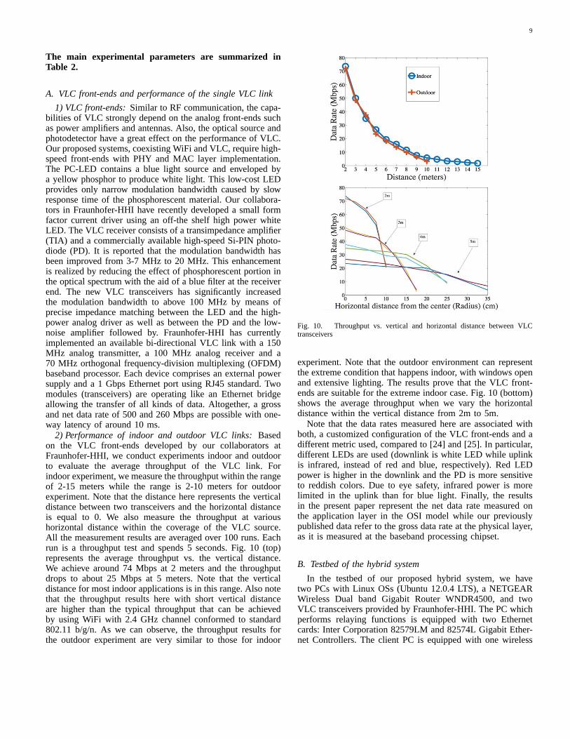
2) Performance of indoor and outdoor VLC links: Basedon the VLC front-ends developed by our collaborators atFraunhofer-HHI, we conduct experiments indoor and outdoorto evaluate the average throughput of the VLC link. Forindoor experiment, we measure the throughput within the rangeof 2-15 meters while the range is 2-10 meters for outdoorexperiment. Note that the distance here represents the verticaldistance between two transceivers and the horizontal distanceis equal to 0. We also measure the throughput at varioushorizontal distance within the coverage of the VLC source.All the measurement results are averaged over 100 runs. Eachrun is a throughput test and spends 5 seconds. Fig. 10 (top)represents the average throughput vs. the vertical distance.We achieve around 74 Mbps at 2 meters and the throughputdrops to about 25 Mbps at 5 meters. Note that the verticaldistance for most indoor applications is in this range. Also notethat the throughput results here with short vertical distanceare higher than the typical throughput that can be achievedby using WiFi with 2.4 GHz channel conformed to standard802.11 b/g/n. As we can observe, the throughput results forthe outdoor experiment are very similar to those for indoor
Fig. 10. Throughput vs. vertical and horizontal distance between VLCtransceivers
experiment. Note that the outdoor environment can representthe extreme condition that happens indoor, with windows openand extensive lighting. The results prove that the VLC front-ends are suitable for the extreme indoor case. Fig. 10 (bottom)shows the average throughput when we vary the horizontaldistance within the vertical distance from 2m to 5m.
Note that the data rates measured here are associated withboth, a customized configuration of the VLC front-ends and adifferent metric used, compared to [24] and [25]. In particular,different LEDs are used (downlink is white LED while uplinkis infrared, instead of red and blue, respectively). Red LEDpower is higher in the downlink and the PD is more sensitiveto reddish colors. Due to eye safety, infrared power is morelimited in the uplink than for blue light. Finally, the resultsin the present paper represent the net data rate measured onthe application layer in the OSI model while our previouslypublished data refer to the gross data rate at the physical layer,as it is measured at the baseband processing chipset.
B. Testbed of the hybrid system
In the testbed of our proposed hybrid system, we havetwo PCs with Linux OSs (Ubuntu 12.0.4 LTS), a NETGEARWireless Dual band Gigabit Router WNDR4500, and twoVLC transceivers provided by Fraunhofer-HHI. The PC whichperforms relaying functions is equipped with two Ethernetcards: Inter Corporation 82579LM and 82574L Gigabit Ether-net Controllers. The client PC is equipped with one wireless
10
TABLE II. PARAMETERS
type of LED blue light with yellow phorspherVLC modulation scheme OFDM
vertical distance measurement range (indoor) 2-15mvertical distance measurement range (outdoor) 2-10m
horizontal distance measurement range (indoor) 0-35cmoperating system Ubuntu 12.0.4 LTSnumber of uses 1-10
mode of WiFi router up to 54 Mbpsbonding driver mode adaptive load balancing (Mode 6)
throughput measurement runs over 100 runsthroughput measurement duration 5 sec
webpage loading time measurement runs over 30 runsblockage duration 5-30 sec
card and one Ethernet card: a Boradcom 802.11n NetworkAdapter and a Broadcom NetXtreme Gigabit Ethernet con-troller respectively. All the NICs support 10/100/1000M speed.
Regarding the network configuration, router’s LAN IP ad-dress is set to 192.168.1.1/24 as default. Referring to Fig. 4, theIP addresses of NIC A-1, NIC B-1, NIC A-2 and NIC B-2 aremanually configured as 192.168.1.200/24, 192.168.1.100/24,192.168.2.200/24 and 192.168.2.100/24 respectively. The IPv4routing table in client PC is shown in Table 3. And anadditional entry in client’s ARP table is added by typing “arp-s 192.168.2.1 ab:ab:ab:ab:ab:ab” in command window withroot privilege.
Fig. 11. Bonding configuration
For the VLC unidirectionallink setup, since the VLC de-vices provided by Fraunhofer-HHI are both transceivers, wemanually turn off the forward-ing function in PC I (relay), inorder to construct a network-level unidirectional VLC chan-nel. Regarding the VLC con-nection establishment, thereare Ethernet ports on the VLCtransceivers, therefore, simply connecting the transceivers tothe PCs with Ethernet cable constructs the wireless VLC link.
C. Testbed of the aggregated system
To implement the aggregation of two wireless links, we useone PC with Linux OSs (Ubuntu 12.0.4 LTS), a NETGEARWireless Dual band Gigabit Router WNDR4500, a clientmode TP-LINK wireless router 150 Mbps TL-WR702N, andalso the two VLC transceivers. The client PC is equippedwith two Ethernet cards: Inter Corporation 82579LM and82574L Gigabit Ethernet Controllers. Both the NICs support10/100/1000M speed. Regarding the network configuration, inorder to construct the aggregated system, we add one lineto /etc/modules: “bonding mode=6”. After that, we modifythe /etc/network/interfaces. We change the eth0 and eth1 toauto DHCP and also add the static logic bond0. The detailedcommands are shown in Fig. 11.
D. Results and Analysis
Iperf [26] is a pervasively used tool to measure the networkperformance. Due the limited bandwidth allocated by the ISP,
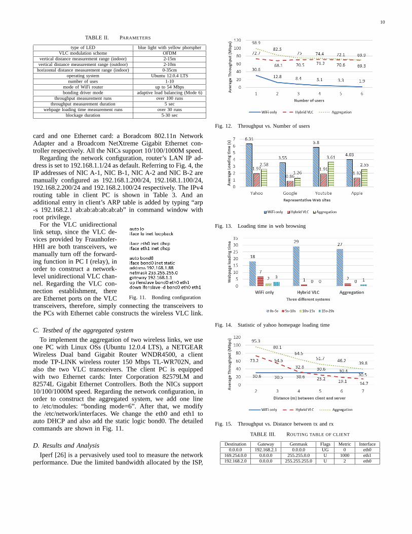
Fig. 12. Throughput vs. Number of users
Fig. 13. Loading time in web browsing
Fig. 14. Statistic of yahoo homepage loading time
Fig. 15. Throughput vs. Distance between tx and rx
TABLE III. ROUTING TABLE OF CLIENT
Destination Gateway Genmask Flags Metric Interface0.0.0.0 192.168.2.1 0.0.0.0 UG 0 eth0
169.254.0.0 0.0.0.0 255.255.0.0 U 1000 eth1192.168.2.0 0.0.0.0 255.255.255.0 U 2 eth0
11
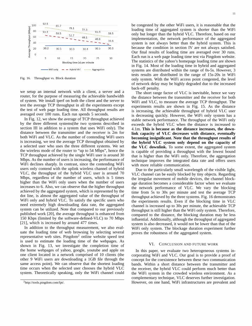
Fig. 16. Throughput vs. Block duration
we setup an internal network with a client, a server and arouter, for the purpose of measuring the achievable bandwidthof system. We install iperf on both the client and the server totest the average TCP throughput in all the experiments exceptthe test of web page loading time. All throughput results areaveraged over 100 runs. Each run spends 5 seconds.
In Fig. 12, we show the average of TCP throughput achievedby the three different systems(the two systems described insection III in addition to a system that uses WiFi only). Thedistance between the transmitter and the receiver is 2m forboth WiFi and VLC. As the number of contending WiFi usersis increasing, we test the average TCP throughput obtained bya selected user who uses the three different systems. We setthe wireless mode of the router to “up to 54 Mbps”, hence theTCP throughput achieved by the single WiFi user is around 30Mbps. As the number of users is increasing, the performance ofWiFi declines sharply. In contrast, since the contending WiFiusers only contend with the uplink wireless channel of hybridVLC, the throughput of the hybrid VLC user is around 70Mbps, regardless of the number of users, which is 5 timeshigher than the WiFi only users when the number of usersincreases to 6. Also, we can observe that the higher throughputachieved by the aggregated system, which is represented by thedot line, is almost the aggregated value of the throughput ofWiFi only and hybrid VLC. To satisfy the specific users whoneed extremely high downloading data rate, the aggregatedsystem can be utilized. Note that compared to our previouslypublished work [20], the average throughput is enhanced from150 Kbps (limited by the software-defined-VLC) to 70 Mbps[21], which is increased by around 477 times.
In addition to the throughput measurement, we also eval-uate the loading time of web browsing by selecting severalrepresentative web sites. Pingdom2 online website speed testis used to estimate the loading time of the webpages. Asshown in Fig. 13, we investigate the completion time ofthe home webpages of yahoo, google, youtube and apple onone client located in a network comprised of 10 clients (theother 9 WiFi users are downloading a 1GB file through thesame access point). We can observe that the shortest loadingtime occurs when the selected user chooses the hybrid VLCsystem. Theoretically speaking, only the WiFi channel could
2http://tools.pingdom.com/fpt/.
be congested by the other WiFi users, it is reasonable that theloading time of aggregated system is shorter than the WiFionly but longer than the hybrid VLC. Therefore, based on ourimplementation, the network performance of the aggregatedsystem is not always better than the hybrid system. This isbecause the condition in section IV are not always satisfied.Our final results of loading time are averaged over 30 runs.Each run is a web page loading time test via Pingdom website.The statistics of the yahoo’s homepage loading time are shownin Fig. 14. Most of the loading time in hybrid and aggregatedsystems are distributed within the range of 0s-5s. However, 3tests results are distributed in the range of 15s-20s in WiFionly system. With the WiFi access point congested, the levelof network delay may be highly degraded due to the increasedback-off penalty.
The short range factor of VLC is inevitable, hence we varythe distance between the transmitter and the receiver for bothWiFi and VLC, to measure the average TCP throughput. Theexperiments results are shown in Fig. 15. As the distanceis increasing, the achievable throughput of hybrid VLC useris decreasing quickly. However, the WiFi only system has astable network performance. The throughput of the WiFi onlyexceeds the hybrid VLC when the distance is increased to4.1m. This is because as the distance increases, the down-link capacity of VLC decreases with distance, eventuallybecoming insignificant. Note that the throughput results ofthe hybrid VLC system only depend on the capacity ofthe VLC downlink. To some extent, the aggregated systemis capable of providing a throughput with the lowest boundthat is higher than the WiFi only. Therefore, the aggregationtechnique improves the integrated data rate and offers userswith more reliable communication.
Due to the particularly small wavelength of the visible light,VLC channel can be easily blocked by tiny objects. Regardingthe irregular movement of mobile devices, the channel block-age duration becomes a considerable factor when we evaluatethe network performance of VLC. We vary the blockingtime from 5s to 30s per minute and test the average TCPthroughput achieved by the three systems. Fig. 16 demonstratesthe experiments results. Even if the blocking time in VLCchannel is increased up to 30s per minute, the achievable TCPthroughput is still higher than the WiFi only system. Therefore,compared to the distance, the blocking duration may be lessinfluential. Additionally, although the throughput of aggregatedsystem is also decreased, it would not be lower than that of theWiFi only system. The blockage duration experiment furtherproves the robustness of the aggregated system.
VI. CONCLUSION AND FUTURE WORK
In this paper, we evaluate two heterogeneous systems in-corporating WiFi and VLC. Our goal is to provide a proof ofconcept for the coexistence between these two communicationbands. Within a short distance between the transmitter andthe receiver, the hybrid VLC could perform much better thanthe WiFi system in the crowded wireless environment. As acomplementary technique, VLC deserves further investigation.However, on one hand, WiFi infrastructures are prevalent and

12
highly acceptable by most consumers; on the other hand,WiFi may outperform VLC in case of long distance datatransmission or the existence of obstacles. We have also proventhrough theoretical analysis that the aggregated system is capa-ble of providing a better network performance than that of thenon-aggregated system for most delay-sensitive applications.Therefore, we conclude that the aggregation between WiFiand VLC is worthy of further study, to effectively utilize theaggregated bandwidth and to lower the network delay.
For future work, we intend to apply aggregation on thehybrid VLC system. To resolve the challenges of opticaluplink in our implemented aggregated system, an approach thatintegrates the symmetric WiFi only link and the asymmetrichybrid VLC link worths investigation. Another direction forfuture research is to investigate the issues related to the spatialreuse of VLC links. This requires the utilization of multipleVLC front-ends. Embedding the optimal traffic allocationalgorithm into the aggregated WiFi-VLC system and acomparative study between the theoretical analysis andthe experimental measurements are also one of our futurework. Given the benefits and results described in this work,VLC is a promising and evolutionary wireless technologythat offers valuable contribution as part of next generationheterogeneous wireless networks.
ACKNOWLEDGMENT
This work was supported in part by the NSF grant ECCS-1331018 and by the Engineering Research Centers Programof the National Science Foundation under NSF CooperativeAgreement No. EEC-0812056.
REFERENCES
[1] I. Cisco, “Cisco visual networking index: Forecast and methodology,2014–2019,” CISCO White paper, pp. 2014–2019, 2015.
[2] M. Kavehrad, “Optical wireless applications: A solution to ease thewireless airwaves spectrum crunch,” in SPIE OPTO. InternationalSociety for Optics and Photonics, 2013, pp. 86 450G–86 450G.
[3] J. M. Kahn and J. R. Barry, “Wireless infrared communications,”Proceedings of the IEEE, vol. 85, no. 2, pp. 265–298, 1997.
[4] T. Komine and M. Nakagawa, “Fundamental analysis for visible-lightcommunication system using led lights,” Consumer Electronics, IEEETransactions on, vol. 50, no. 1, pp. 100–107, 2004.
[5] S. Rajagopal, R. D. Roberts, and S.-K. Lim, “IEEE 802.15. 7 visi-ble light communication: modulation schemes and dimming support,”Communications Magazine, IEEE, vol. 50, no. 3, pp. 72–82, 2012.
[6] M. B. Rahaim, A. M. Vegni, and T. D. C. Little, “A hybrid ra-dio frequency and broadcast visible light communication system.” inGLOBECOM Workshops, 2011, pp. 792–796.
[7] C. Lee, C. Tan, H. Wong, and M. Yahya, “Performance evaluation ofhybrid VLC using device cost and power over data throughput criteria,”in SPIE Optical Engineering+ Applications. International Society forOptics and Photonics, 2013, pp. 88 451A–88 451A.
[8] H. Chowdhury, I. Ashraf, and M. Katz, “Energy-efficient connectivityin hybrid radio-optical wireless systems,” in Wireless CommunicationSystems (ISWCS 2013), Proceedings of the Tenth International Sympo-sium on. VDE, 2013, pp. 1–5.
[9] Z. Huang and Y. Feng, “Design and demonstration of room divisionmultiplexing-based hybrid vlc network,” Chinese Optics Letters, vol. 11,no. 6, p. 060603, 2013.
[10] S. Schmid, G. Corbellini, S. Mangold, and T. R. Gross, “LED-to-LED visible light communication networks,” in Proceedings of thefourteenth ACM international symposium on Mobile ad hoc networkingand computing. ACM, 2013, pp. 1–10.
[11] K.-D. Langer and J. Grubor, “Recent developments in optical wire-less communications using infrared and visible light,” in TransparentOptical Networks, 2007. ICTON’07. 9th International Conference on,vol. 3. IEEE, 2007, pp. 146–151.
[12] A. L. Ramaboli, O. E. Falowo, and A. H. Chan, “Bandwidth aggregationin heterogeneous wireless networks: A survey of current approaches andissues,” Journal of Network and Computer Applications, vol. 35, no. 6,pp. 1674–1690, 2012.
[13] G. P. Koudouridis, R. Aguero, E. Alexandri, J. Choque, K. Dimou,H. Karimi, H. Lederer, J. Sachs, and R. Sigle, “Generic link layerfunctionality for multi-radio access networks,” in IST Mobile andWireless Communications Summit, 2005.
[14] G. P. Koudouridis, H. R. Karimi, and K. Dimou, “Switched multi-radiotransmission diversity in future access networks,” in VTC2005-fall:2005 IEEE 62nd vehicular technology conference, 1-4, proceedings,2005, pp. 235–239.
[15] A. Yaver and G. P. Koudouridis, “Performance evaluation of multi-radio transmission diversity: QoS support for delay sensitive services,”in Vehicular Technology Conference, 2009. VTC Spring 2009. IEEE69th. IEEE, 2009, pp. 1–5.
[16] J.-O. Kim, T. Ueda, and S. Obana, “Mac-level measurement basedtraffic distribution over ieee 802.11 multi-radio networks,” ConsumerElectronics, IEEE Transactions on, vol. 54, no. 3, pp. 1185–1191, 2008.
[17] J.-O. Kim, “Feedback-based traffic splitting for wireless terminalswith multi-radio devices,” consumer electronics, IEEE Transactions on,vol. 56, no. 2, pp. 476–482, 2010.
[18] J.-O. Kim, P. Davis, T. Ueda, and S. Obana, “Splitting downlinkmultimedia traffic over WiMax and WiFi heterogeneous links basedon airtime-balance,” Wireless Communications and Mobile Computing,vol. 12, no. 7, pp. 598–614, 2012.
[19] D. Senie, “Using the SOCK-PACKET mechanism in linux to gaincomplete control of an ethernet interface,” Internet:.(Retrieved Apr. 24,2002), 2002.
[20] S. Shao, A. Khreishah, M. B. Rahaim, H. Elgala, M. Ayyash, T. D. C.Little, and J. Wu, “An indoor hybrid WiFi-VLC internet access system,”CARTOON Workshop of CellulAR Traffic Offloading to OpportunisticNetworks, Philidelphia, PA, October, 2014.
[21] M. Ayyash, H. Elgala, A. Khreishah, V. Jungnickel, T. Little, S. Shao,M. Rahaim, D. Schulz, J. Hilt, and R. Freund, “Coexistence of WiFiand LiFi towards 5G: Concepts, Opportunities, and Challenges,” IEEECommunication Magazine, Submitted, 2015.
[22] T. Davis, W. Tarreau, C. Gavrilov, C. N. Tindel, J. Girouard, andJ. Vosburgh, “Linux ethernet bonding driver howto,” available asdownload (bonding. txt) from the Linux Channel Bonding project Website http://sourceforge. net/projects/bonding/(November 2007), 2011.
[23] G. Bianchi, L. Fratta, and M. Oliveri, “Performance evaluation andenhancement of the CSMA/CA mac protocol for 802.11 wirelesslans,” in Personal, Indoor and Mobile Radio Communications, 1996.PIMRC’96., Seventh IEEE International Symposium on, vol. 2. IEEE,1996, pp. 392–396.
[24] K.-D. Langer, J. Hilt, D. Shulz, F. Lassak, F. Hartlieb, C. Kottke,L. Grobe, V. Jungnickel, and A. Paraskevopoulos, “Optoelectronics &communications rate-adaptive visible light communication at 500Mb/sarrives at plug and play,” SPIE Newsroom, 14 November 2013.
[25] L. Grobe, A. Paraskevopoulos, J. Hilt, D. Schulz, F. Lassak, F. Hartlieb,C. Kottke, V. Jungnickel, and K.-D. Langer, “High-speed visible lightcommunication systems,” Communications Magazine, IEEE, vol. 51,no. 12, pp. 60–66, 2013.
[26] A. Tirumala, F. Qin, J. Dugan, J. Ferguson, and K. Gibbs, “Iperf:The TCP/UDP bandwidth measurement tool,” htt p://dast. nlanr.net/Projects, 2005.