Embed Size (px)
Citation preview

1. Description
The macerating system of this unit is installed in a case, specifically designed for horizontal outlet spigots. This macerator is manufactured in a factory which is quality certified to ISO 9001(2000) accredited by AFAQ. The correct operation of your unit depends on correct installation and usage.
Please pay particular attention to the following:
Possible danger to personnel Warning of possible electrical hazard
“ATTENTION” This is a general warning that failure to follow instructions could result in poor functioning of the unit.
This equipment benefits from the latest technological innovations concerning soundproofing. To benefit fully from the advantages provided by this new generation of appliances, it is important to comply with the installation instructions in section 5.
2. List of Accessories included
32 x 50 90 x 110
20 x 32
A B C D
E F G H
I J
x1 x5 x1 x1
x2 x1 x1 x2
x2 x4
Hose clip for discharge elbow Blanking off inlet cap
Inlet connector Optional Euro 22-32mm reducer Discharge hose Floor mounting bracket
Discharge hose clip Rubber feet
Hose clip for WC pan spigotDischarge elbow
Please also see “10 golden rules” for correct Saniflo installation on www.saniflo.co.uk
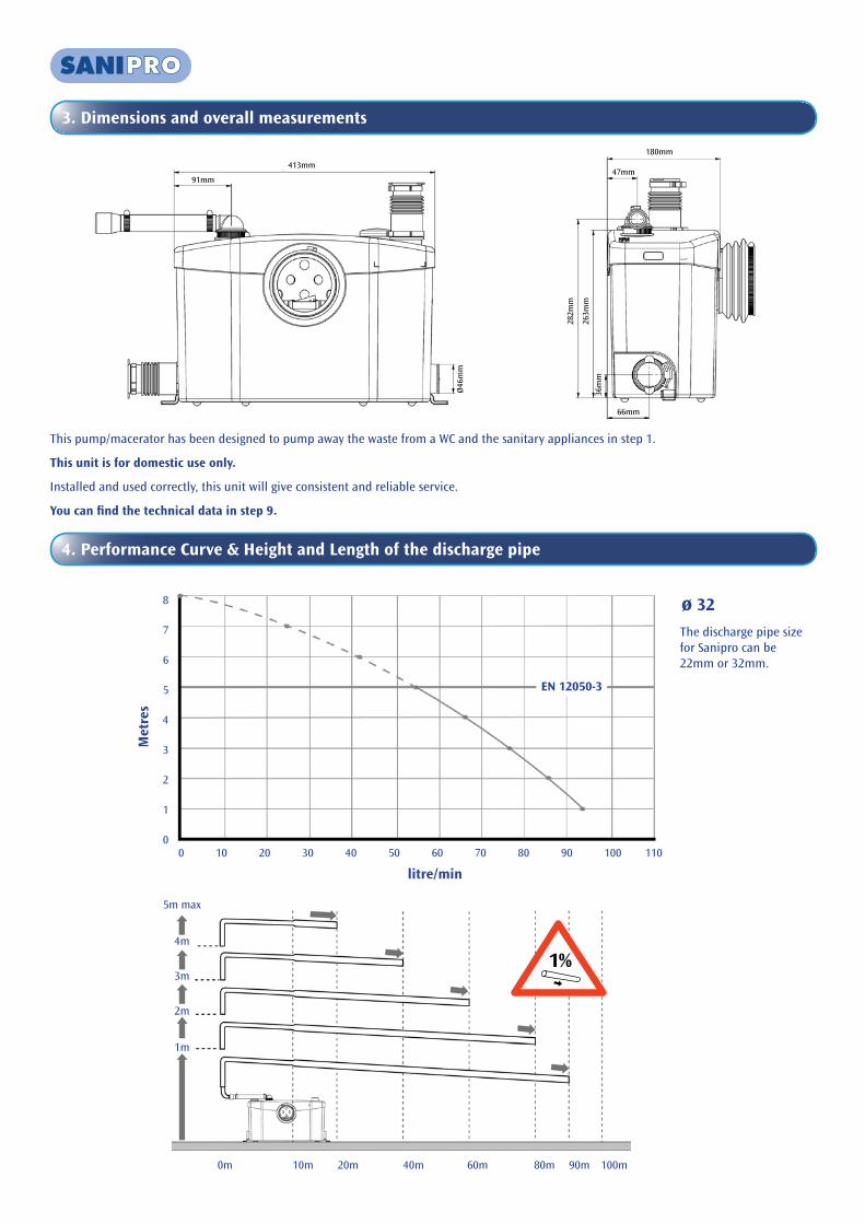
3. Dimensions and overall measurements
This pump/macerator has been designed to pump away the waste from a WC and the sanitary appliances in step 1.
This unit is for domestic use only.
Installed and used correctly, this unit will give consistent and reliable service.
You can find the technical data in step 9.
4. Performance Curve & Height and Length of the discharge pipe
litre/min
Met
res
ø 32
0 10 20 30 40 50 60 70 80 90 100 110
8
7
6
5
4
3
2
1
0
EN 12050-3
0m 10m 20m 40m 60m 80m 90m 100m
5m max
4m
3m
2m
1m
1%
The discharge pipe size for Sanipro can be 22mm or 32mm.
413mm
91mm
Ø46
mm
282m
m
263m
m
36m
m
180mm
47mm
66mm
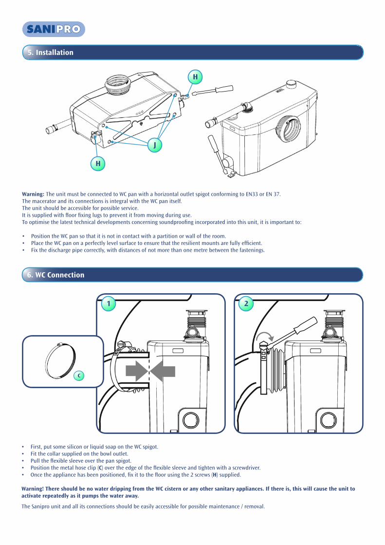
5. Installation
Warning: The unit must be connected to WC pan with a horizontal outlet spigot conforming to EN33 or EN 37.The macerator and its connections is integral with the WC pan itself.The unit should be accessible for possible service.It is supplied with floor fixing lugs to prevent it from moving during use.To optimise the latest technical developments concerning soundproofing incorporated into this unit, it is important to:
• Position the WC pan so that it is not in contact with a partition or wall of the room.• Place the WC pan on a perfectly level surface to ensure that the resilient mounts are fully efficient.• Fix the discharge pipe correctly, with distances of not more than one metre between the fastenings.
J
H
H
6. WC Connection
• First, put some silicon or liquid soap on the WC spigot.• Fit the collar supplied on the bowl outlet.• Pull the flexible sleeve over the pan spigot.• Position the metal hose clip (C) over the edge of the flexible sleeve and tighten with a screwdriver.• Once the appliance has been positioned, fix it to the floor using the 2 screws (H) supplied.
Warning! There should be no water dripping from the WC cistern or any other sanitary appliances. If there is, this will cause the unit to activate repeatedly as it pumps the water away.
The Sanipro unit and all its connections should be easily accessible for possible maintenance / removal.
1 2
C

7. Connections of extra sanitary appliances
8. Connection of discharge pipework
AF
G
IA
B
F
G
I
A
B
I
Insert the discharge elbow (A) into the rubber discharge pipe which rises up through the lid, turn to the desired direction and secure with the hose clip provided (32-50mm) (B). Then connect the hose to it using the 20-32mm hose clip (I), making sure the hose is not kinked.
E
B
B
See figs 1 and 2 for connections that may be required for sanitary appliances.
E
B
B2
I
Closed
1
Plugging side inlet
D

9. Technical advice for discharge pipework
4
31 2
6
Ø 28 / 32 / 40mm
Ø 2
2 / 2
8 / 3
2mm
max
. 5m
120mm min.
Ø 40
2nd possibility for connection of wash basin
22mm28mm32mm40mm
100/110mm
1%
3%
1%
Vertical before horizontal
5
1 Horizontal pipe runs must have a minimum fall of 1:100 (10mm per metre) to the soil stack.
2 If a vertical lift is required, it must be made before the horizontal run at the start of the piperun.
3 We would recommend that a drain-off point is installed to allow the discharge pipework to be drained down before any service work.
4 If the discharge pipework runs to a level considerably lower than the unit, the resultant siphoning effect can suck out the water seal in the unit. Fitting an air admittance valve capable of withstanding 10psi pressure (BBA approved) at the high point of the pipe run will overcome this problem.
5 Ensure all external pipework is adequately lagged to avoid the possibility of freezing.
6 The discharge pipework must be connected to the soil stack using an appropriate strap on boss.
N.B. Any elbow on the discharge pipe of the unit will create friction loss (roughly 50cm per elbow to be deducted from the vertical pumping specification).
Always use smooth bends (or 2 x 45 degree bends together) and not 90 degree elbows.
Note. The discharge pipework should be copper or rigid solvent weld plastic.
Air Admittance Valve
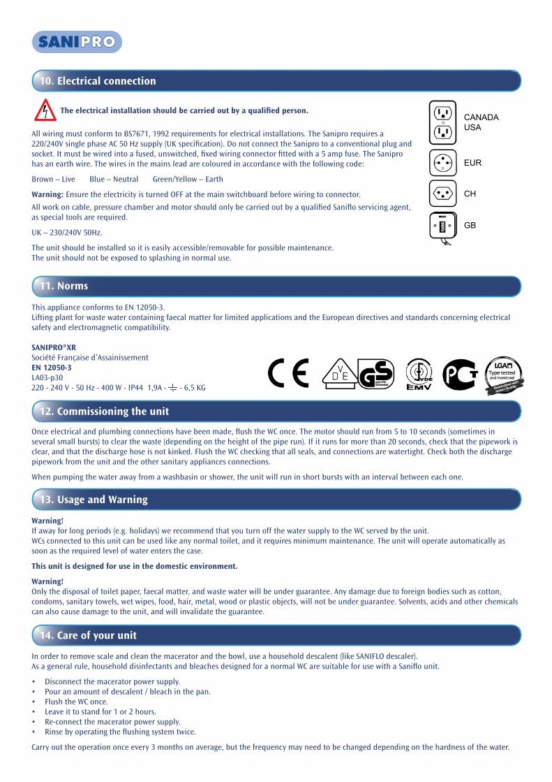
11. Norms
This appliance conforms to EN 12050-3.Lifting plant for waste water containing faecal matter for limited applications and the European directives and standards concerning electrical safety and electromagnetic compatibility.
SANIPRO®XRSociété Française d’AssainissementEN 12050-3LA03-p30220 - 240 V - 50 Hz - 400 W - IP44 1,9A - - 6,5 KG
12. Commissioning the unit
Once electrical and plumbing connections have been made, flush the WC once. The motor should run from 5 to 10 seconds (sometimes in several small bursts) to clear the waste (depending on the height of the pipe run). If it runs for more than 20 seconds, check that the pipework is clear, and that the discharge hose is not kinked. Flush the WC checking that all seals, and connections are watertight. Check both the discharge pipework from the unit and the other sanitary appliances connections.
When pumping the water away from a washbasin or shower, the unit will run in short bursts with an interval between each one.
13. Usage and Warning
Warning!If away for long periods (e.g. holidays) we recommend that you turn off the water supply to the WC served by the unit.WCs connected to this unit can be used like any normal toilet, and it requires minimum maintenance. The unit will operate automatically as soon as the required level of water enters the case.
This unit is designed for use in the domestic environment.
Warning!Only the disposal of toilet paper, faecal matter, and waste water will be under guarantee. Any damage due to foreign bodies such as cotton, condoms, sanitary towels, wet wipes, food, hair, metal, wood or plastic objects, will not be under guarantee. Solvents, acids and other chemicals can also cause damage to the unit, and will invalidate the guarantee.
14. Care of your unit
In order to remove scale and clean the macerator and the bowl, use a household descalent (like SANIFLO descaler). As a general rule, household disinfectants and bleaches designed for a normal WC are suitable for use with a Saniflo unit.
• Disconnect the macerator power supply.• Pour an amount of descalent / bleach in the pan.• Flush the WC once.• Leave it to stand for 1 or 2 hours.• Re-connect the macerator power supply.• Rinse by operating the flushing system twice.
Carry out the operation once every 3 months on average, but the frequency may need to be changed depending on the hardness of the water.
10. Electrical connection
The electrical installation should be carried out by a qualified person.
All wiring must conform to BS7671, 1992 requirements for electrical installations. The Sanipro requires a 220/240V single phase AC 50 Hz supply (UK specification). Do not connect the Sanipro to a conventional plug and socket. It must be wired into a fused, unswitched, fixed wiring connector fitted with a 5 amp fuse. The Sanipro has an earth wire. The wires in the mains lead are coloured in accordance with the following code:
Brown – Live Blue – Neutral Green/Yellow – Earth
Warning: Ensure the electricity is turned OFF at the main switchboard before wiring to connector.
All work on cable, pressure chamber and motor should only be carried out by a qualified Saniflo servicing agent, as special tools are required.
UK – 230/240V 50Hz.
The unit should be installed so it is easily accessible/removable for possible maintenance. The unit should not be exposed to splashing in normal use.
CANADAUSA
EUR
CH
GB

15. Maintenance
No need of any particular maintenance.This unit is fitted with an active carbon filter, and requires no external venting. This filter has to be changed every year.
16. Fault Finding / Remedies
For the most part any inconsistencies in the operation of the unit will be minor and easily rectified. Please refer to the chart below. If the problem cannot be easily remedied in this way. Please call our Service organisation.
IN ALL CASES, YOU MUST DISCONNECT THE MACERATOR FROM THE POWER SUPPLY
If the problem cannot be easily remedied in this way, please call our Service organisation.
ALL WORK INVOLVING DISMANTLING OF THE APPLIANCE MUST BE CARRIED OUT BY AN APPROVED REPAIR AGENT
DISCONNECT THE ELECTRICAL POWER SUPPLY, BEFORE ATTEMPTING ANY WORK ON THE UNIT.
SYMPTOMS PROBABLE CAUSES REMEDIES
• The unit stops• An object is blocking the blades• The unit has been running for too long and the
(self re-setting) thermal cut out has engaged
• Call approved service engineer• The unit will reset itself
• The motor intermittently activates• The connected sanitary devices are dripping• The non-return valve is faulty
• Check the installation upstream• Clean or replace the non-return valve
(externally mounted)
• The water in the WC pan goes down very slowly and is pumped away in bursts
• The air vent (under carbon filter) is clogged up• The WC pan is partially blocked
• Clear the air vent• Clear pan
• The motor operates normally, but continues to run for a long time
• The length or height of the installation is over the specification, or there are too many bends/elbows
• The pump chamber is blocked
• Check the installation• Call approved service engineer
• The motor does not activate• The electrical power supply is not active• The motor or the control system is defective
• Restore the electrical supply• Call approved service engineer
• The motor emits a rattling or crunching sound, hums, but does not run
• Foreign object in the box• Problem with the motor or the control system
• Call approved service engineer
• Cloudy water comes up into the shower tray (units with side inlets)
• Shower installed too low as compared with the macerator unit
• Hinged side inlet discs clogged up
• Check the installation• Clean the hinged discs (see section 17)• Call approved service engineer

17. Removal
DISCONNECT THE ELECTRICAL POWER SUPPLY BEFORE ANY SERVICE
REMOVING THE UNIT FROM THE WC SUITE
Disconnect the electrical power supply.
Turn off the water feed to the WC cistern. Bail out as much water as possible from the cistern.
Drain down any vertical discharge pipework and remove discharge hose from elbow.
Disconnect any inlet pipes from the unit.
Unscrew the 2 fastening screws (to the floor) if fitted.
Loosen the hose clip securing the flexible connector and pull off the WC spigot, now slide the unit out from behind the WC.
HINGED SIDE INLET VALVES CLOGGEDRemove the sleeves and use a screwdriver to free or clean the rubber flaps if necessary.
1
2
3
4
5
6
18. Guarantee
2 year guarantee as from its date of purchase subject to correct installation and usage.
1
2
3
4
5
6
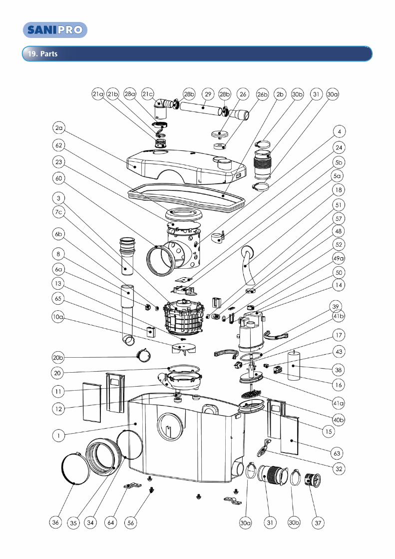
19. Parts