Embed Size (px)
Citation preview
1
Database System Database System Concepts Concepts and Architectureand Architecture
Umm –Al Qura University College of Computer Science – Al Lith
Lecturer: Dr. Ali Al Najjar 2nd Semester 1435/1436 H
22
2
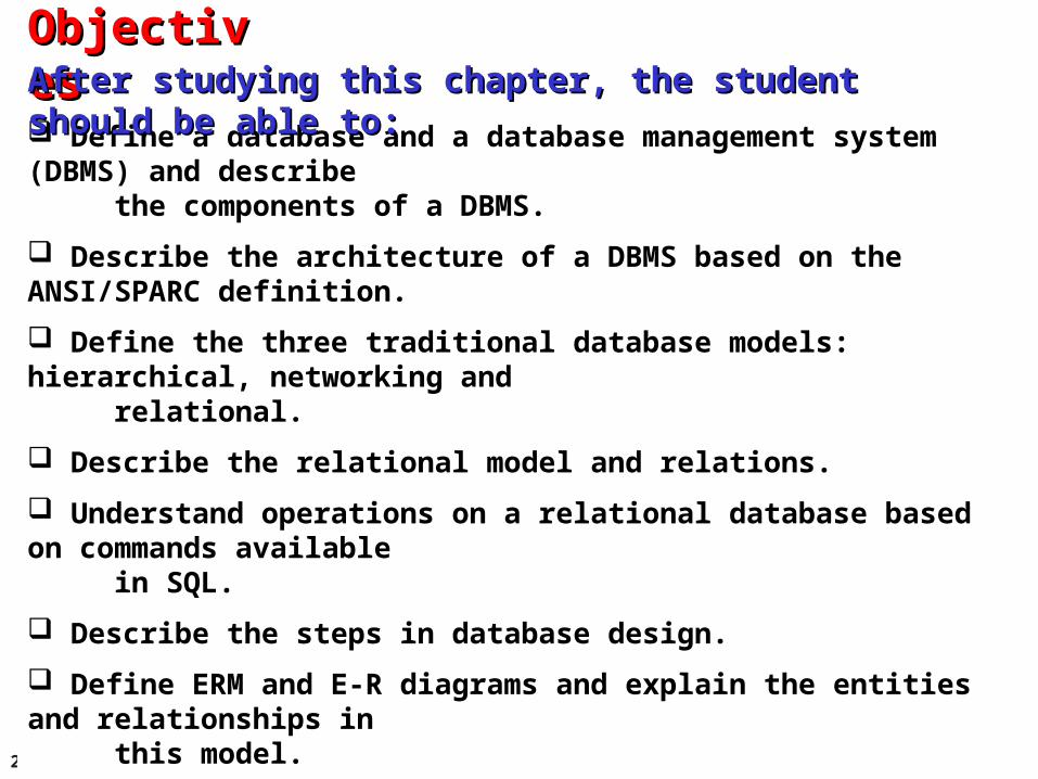
Define a database and a database management system (DBMS) and describe the components of a DBMS.
Describe the architecture of a DBMS based on the ANSI/SPARC definition.
Define the three traditional database models: hierarchical, networking and relational.
Describe the relational model and relations.
Understand operations on a relational database based on commands available in SQL.
Describe the steps in database design.
Define ERM and E-R diagrams and explain the entities and relationships in this model.
Define the hierarchical levels of normalization and understand the rationale for normalizing the relations.
List database types other than the relational model.
ObjectivesObjectivesAfter studying this chapter, the student should be able to:After studying this chapter, the student should be able to:
3
2-1 INTRODUCTION2-1 INTRODUCTION
Data storage traditionally used individual, unrelated Data storage traditionally used individual, unrelated files, sometimes called files, sometimes called flat filesflat files. In the past, each . In the past, each application program in an organization used its own file. application program in an organization used its own file. In a university, for example, each department might In a university, for example, each department might have its own set of files: the record office kept a file have its own set of files: the record office kept a file about the student information and their grades, the about the student information and their grades, the scheduling office kept the name of the professors and scheduling office kept the name of the professors and the courses they were teaching, the payroll department the courses they were teaching, the payroll department kept its own file about the whole staff and so on. Today, kept its own file about the whole staff and so on. Today, however, all of these flat files can be combined in a however, all of these flat files can be combined in a single entity; the database for the whole university.single entity; the database for the whole university.
4
Definition
Although it is difficult to give a universally agreed definition of a database, we use the following common definition:
Definition:A database is a collection of related, logically
coherent data used by the application programs in an organization.
i
5
Advantages of databases
Comparing the flat-file system, we can mention several advantages for a database system.
Less redundancy
In a flat-file system there is a lot of redundancy. For example, in the flat file system for a university, the names of professors and students are stored in more than one file.
Inconsistency avoidance
If the same piece of information is stored in more than one place, then any changes in the data need to occur in all places that data is stored.
6
Efficiency
A database is usually more efficient that a flat file system, because a piece of information is stored in fewer locations.
Data integrity
In a database system it is easier to maintain data integrity (see Chapter 16), because a piece of data is stored in fewer locations.
Confidentiality
It is easier to maintain the confidentiality of the information if the storage of data is centralized in one location.
7
2-2 DATABASE MANAGEMENT SYSTEMS2-2 DATABASE MANAGEMENT SYSTEMS
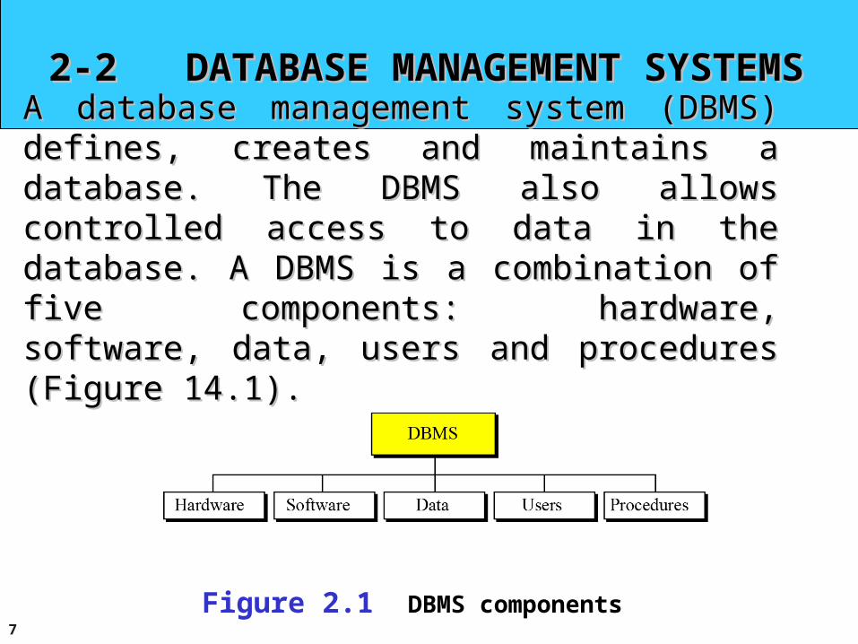
A database management system (DBMS) defines, A database management system (DBMS) defines, creates and maintains a database. The DBMS also creates and maintains a database. The DBMS also allows controlled access to data in the database. A allows controlled access to data in the database. A DBMS is a combination of five components: hardware,DBMS is a combination of five components: hardware,software, data, users and procedures (Figure 14.1).software, data, users and procedures (Figure 14.1).
Figure 2.1 DBMS components
8
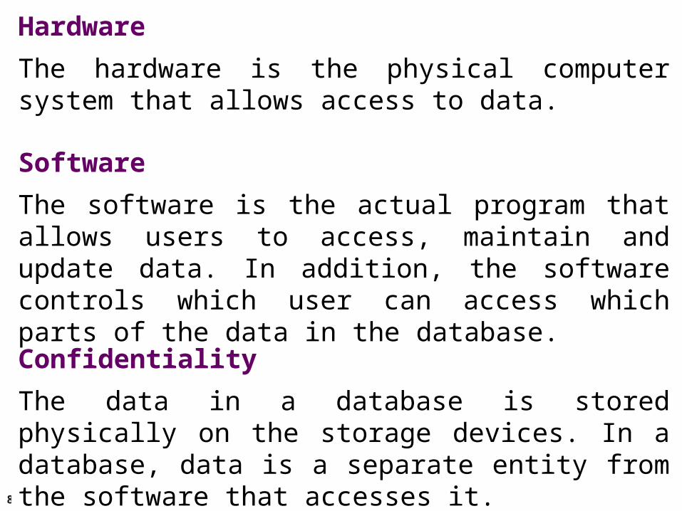
Hardware
The hardware is the physical computer system that allows access to data.
Software
The software is the actual program that allows users to access, maintain and update data. In addition, the software controls which user can access which parts of the data in the database.
Confidentiality
The data in a database is stored physically on the storage devices. In a database, data is a separate entity from the software that accesses it.
9
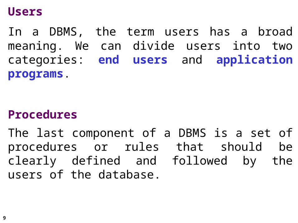
Users
In a DBMS, the term users has a broad meaning. We can divide users into two categories: end users and application programs.
Procedures
The last component of a DBMS is a set of procedures or rules that should be clearly defined and followed by the users of the database.
10
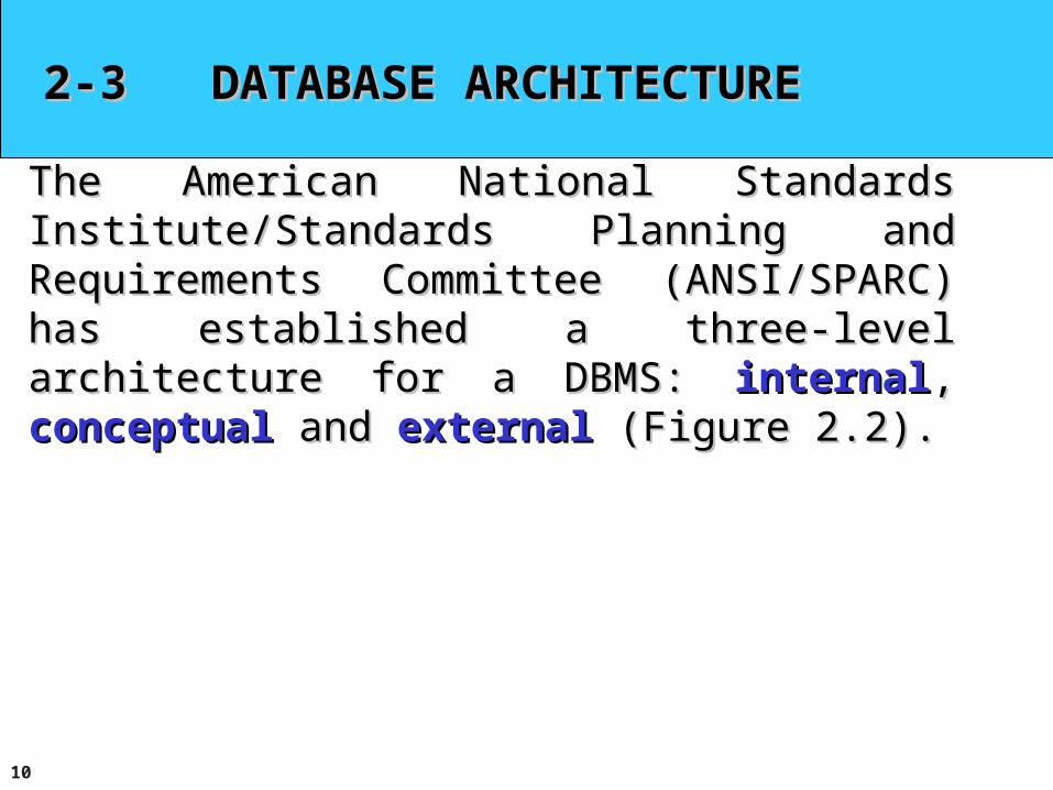
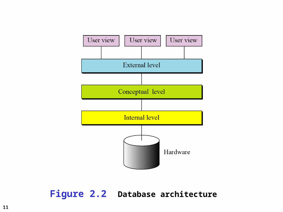
2-3 DATABASE ARCHITECTURE2-3 DATABASE ARCHITECTURE
The American National Standards Institute/Standards The American National Standards Institute/Standards Planning and Requirements Committee (ANSI/SPARC) Planning and Requirements Committee (ANSI/SPARC) has established a three-level architecture for a DBMS: has established a three-level architecture for a DBMS: internalinternal, , conceptualconceptual and and externalexternal (Figure 2.2). (Figure 2.2).
11
Figure 2.2 Database architecture
12
Internal levelThe internal level determines where data is actually stored on the storage devices. This level deals with low-level access methods and how bytes are transferred to and from storage devices. In other words, the internal level interacts directly with the hardware.
Conceptual levelThe conceptual level defines the logical view of the data. The data model is defined on this level, and the main functions of the DBMS, such as queries, are also on this level. The DBMS changes the internal view of data to the external view that users need to see. The conceptual level is an intermediary and frees users from dealing with the internal level.
13
External levelThe external level interacts directly with the user (end users or application programs). It changes the data coming from the conceptual level to a format and view that is familiar to the users.
14
2- 4 2- 4 DBMS Languages
Data definition language (DDL)Used by the DBA and database designers to specify the conceptual schema of a database.
Commands in this category modify the structure of the database by creating, replacing, altering, or dropping objects such as tables, indexes, and views.
15
DBMS Languages (cont'd.)
Data Control Language (DCL)This category includes commands that protect the integrity of
the database and the consistency of data by controlling and managing the access to the database structures. These commands are often divided into transaction control commands session control commands, and system control commands.
e.g. create, grand, invoke.
16
DBMS Languages (cont'd.)
Data Manipulation Language (DML)Commands in this category allow you to
manipulate data in existing database objects. The most popular commands in this category are
INSERT, UPDATE, and DELETE. Often it is necessary to use the SELECT command to specify the set of data that should be updated or deleted. This is the reason why SELECT sometimes is included in the DML category.
17
DBMS Languages (cont'd.)
Data Retrieval CommandThis category contains only one command: SELECT.
This command is a cornerstone of SQL and allows users to query necessary data from the database. Because of its importance and widespread usage, if is often considered in a separate category of its own.
18
2-5 DBMS Interfaces
Menu-based interfaces for Web clients or browsing
Forms-based interfaces Graphical user interfaces Natural language interfaces Speech input and output Interfaces for parametric users Interfaces for the DBA
19
2-6 DATABASE MODELS2-6 DATABASE MODELS
A database model defines the logical design of data. The A database model defines the logical design of data. The model also describes the relationships between different model also describes the relationships between different parts of the data. In the history of database design, three parts of the data. In the history of database design, three models have been in use: the hierarchical model, the models have been in use: the hierarchical model, the network model and the relational model.network model and the relational model.
20
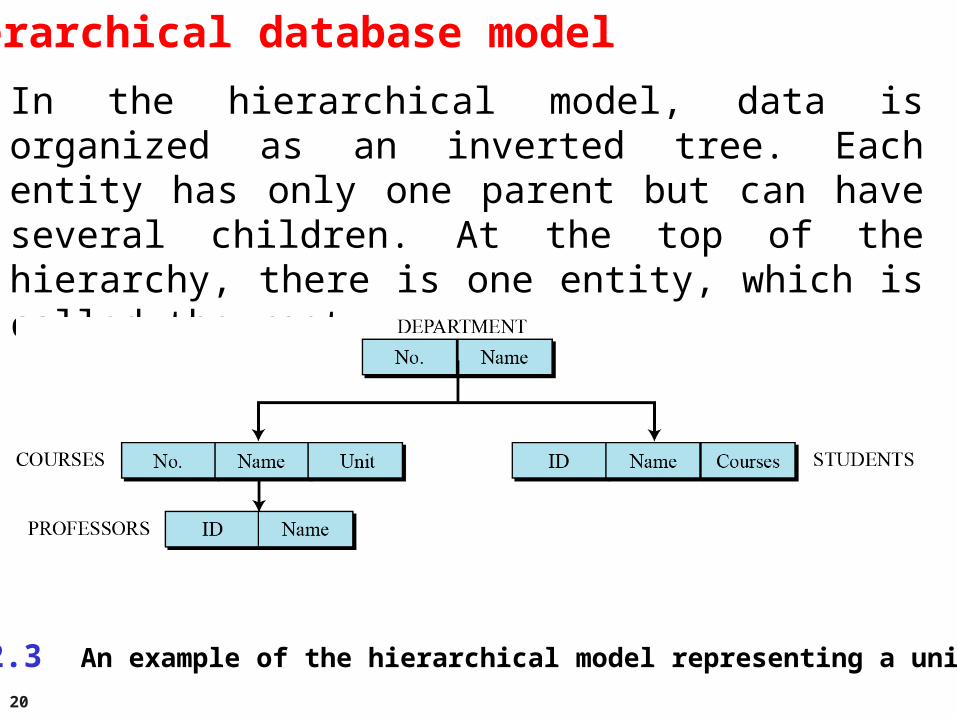
Hierarchical database model
In the hierarchical model, data is organized as an inverted tree. Each entity has only one parent but can have several children. At the top of the hierarchy, there is one entity, which is called the root.
Figure 2.3 An example of the hierarchical model representing a university
21
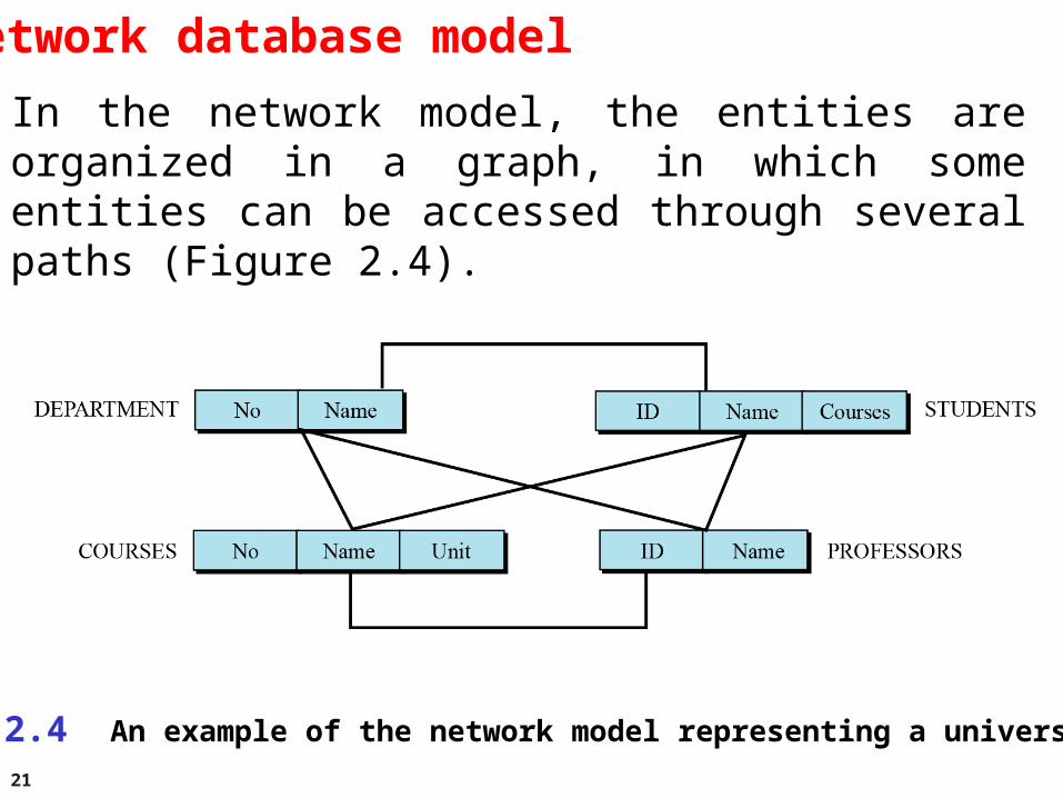
Network database model
In the network model, the entities are organized in a graph, in which some entities can be accessed through several paths (Figure 2.4).
Figure 2.4 An example of the network model representing a university
22
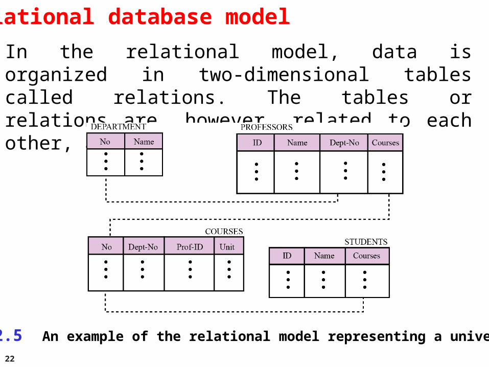
Relational database model
In the relational model, data is organized in two-dimensional tables called relations. The tables or relations are, however, related to each other, as we will see shortly.
Figure 2.5 An example of the relational model representing a university
23
2-7 THE RELATIONAL DATABASE MODEL2-7 THE RELATIONAL DATABASE MODEL
In the In the relational database management systemrelational database management system (RDBMS)(RDBMS), the data is represented as a set of , the data is represented as a set of relationsrelations..
24
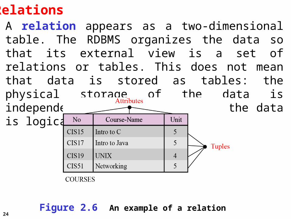
RelationsA relation appears as a two-dimensional table. The RDBMS organizes the data so that its external view is a set of relations or tables. This does not mean that data is stored as tables: the physical storage of the data is independent of the way in which the data is logically organized.
Figure 2.6 An example of a relation
25
A relation in an RDBMS has the following features:
Name. Each relation in a relational database should have a name that is unique among other relations.
Attributes. Each column in a relation is called an attribute. The attributes are the column headings in the table in Figure 2.6.
Tuples. Each row in a relation is called a tuple. A tuple defines a collection of attribute values. The total number of rows in a relation is called the cardinality of the relation. Note that the cardinality of a relation changes when tuples are added or deleted. This makes the database dynamic.
26
2-8 2-8 Database Table Keys
Definition: A key of a relation is a subset of attributes with the following attributes: Unique identification Non-redundancy
27
2-8 2-8 Database Table Keys (cont'd.)
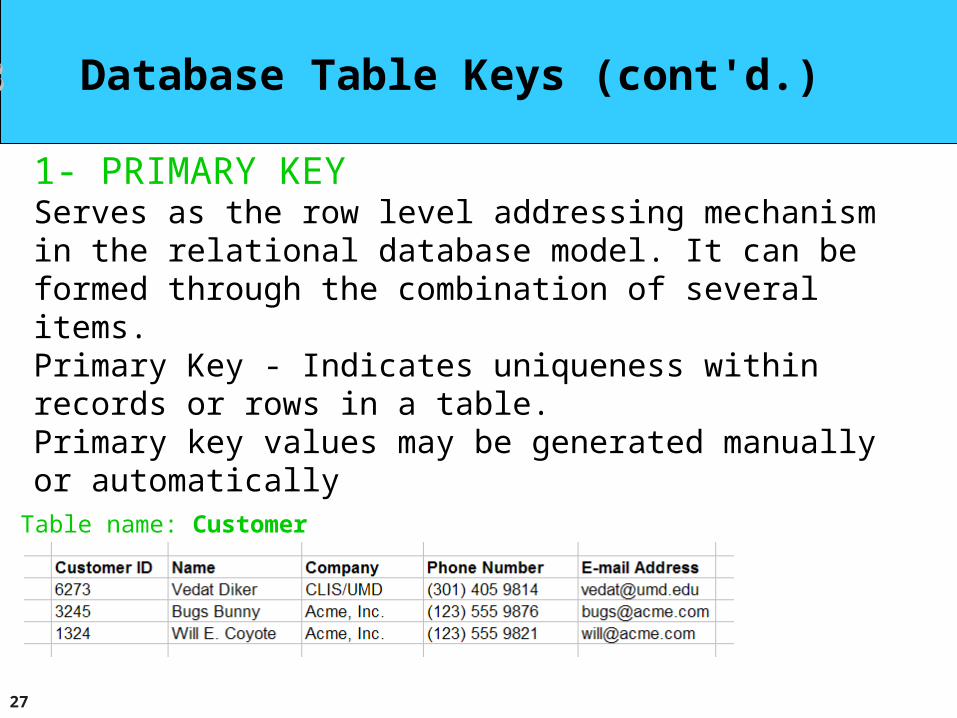
1- PRIMARY KEY Serves as the row level addressing mechanism in the relational database model. It can be formed through the combination of several items. Primary Key - Indicates uniqueness within records or rows in a table. Primary key values may be generated manually or automatically
Table name: Customer
28
2-8 2-8 Database Table Keys (cont'd.)
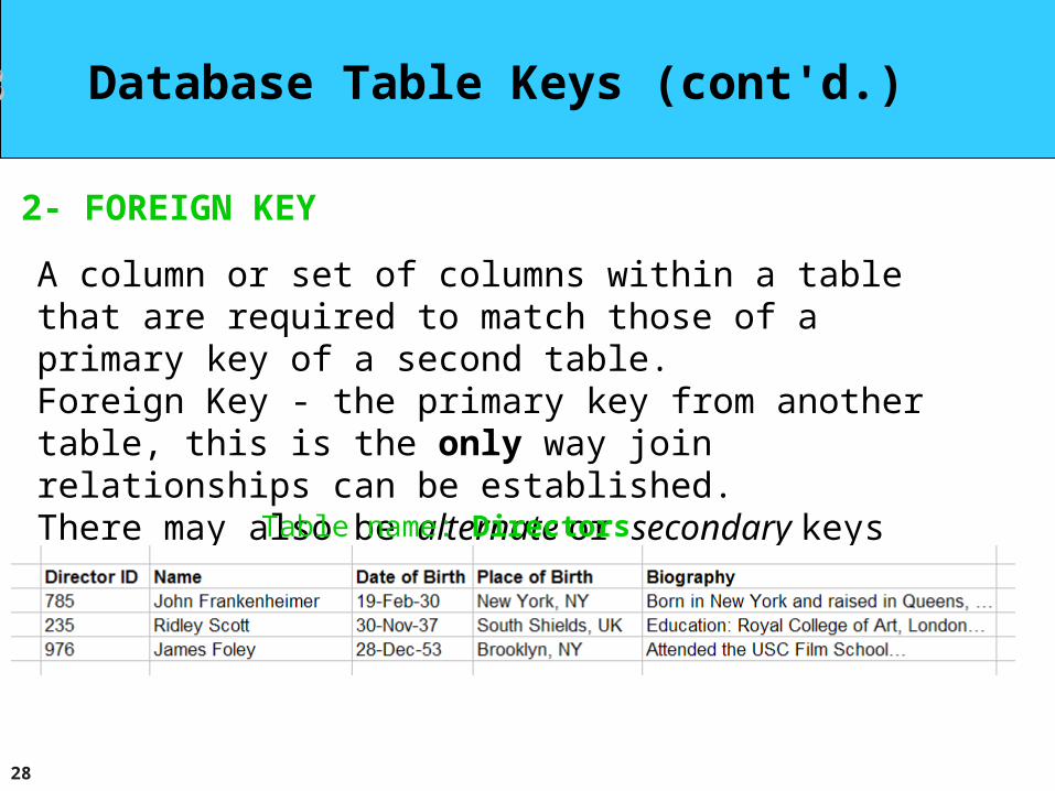
2- FOREIGN KEY
A column or set of columns within a table that are required to match those of a primary key of a second table. Foreign Key - the primary key from another table, this is the only way join relationships can be established. There may also be alternate or secondary keys within a table.
Table name: Directors
29
2-8 2-8 Database Table Keys (cont'd.)
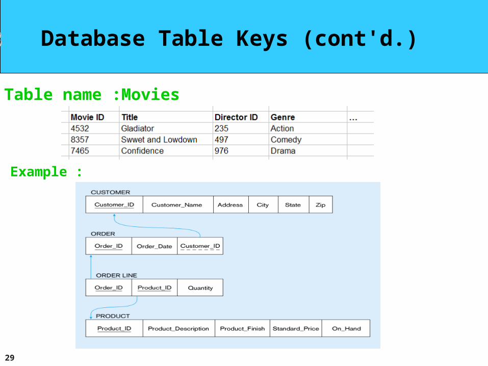
Table name :Movies
Example :
30
2-8 OPERATIONS ON RELATIONS2-8 OPERATIONS ON RELATIONS
In a relational database we can define several operations In a relational database we can define several operations to create new relations based on existing ones. We to create new relations based on existing ones. We define nine operations in this section: insert, delete, define nine operations in this section: insert, delete, update, select, project, join, union, intersection and update, select, project, join, union, intersection and difference. Instead of discussing these operations in the difference. Instead of discussing these operations in the abstract, we describe each operation as defined in the abstract, we describe each operation as defined in the database query language SQL (Structured Query database query language SQL (Structured Query Language).Language).
31
Structured Query Language
Structured Query Language (SQL) is the language standardized by the American National Standards Institute (ANSI) and the International Organization for Standardization (ISO) for use on relational databases. It is a declarative rather than procedural language, which means that users declare what they want without having to write a step-by-step procedure. The SQL language was first implemented by the Oracle Corporation in 1979, with various versions of SQL being released since then.
32
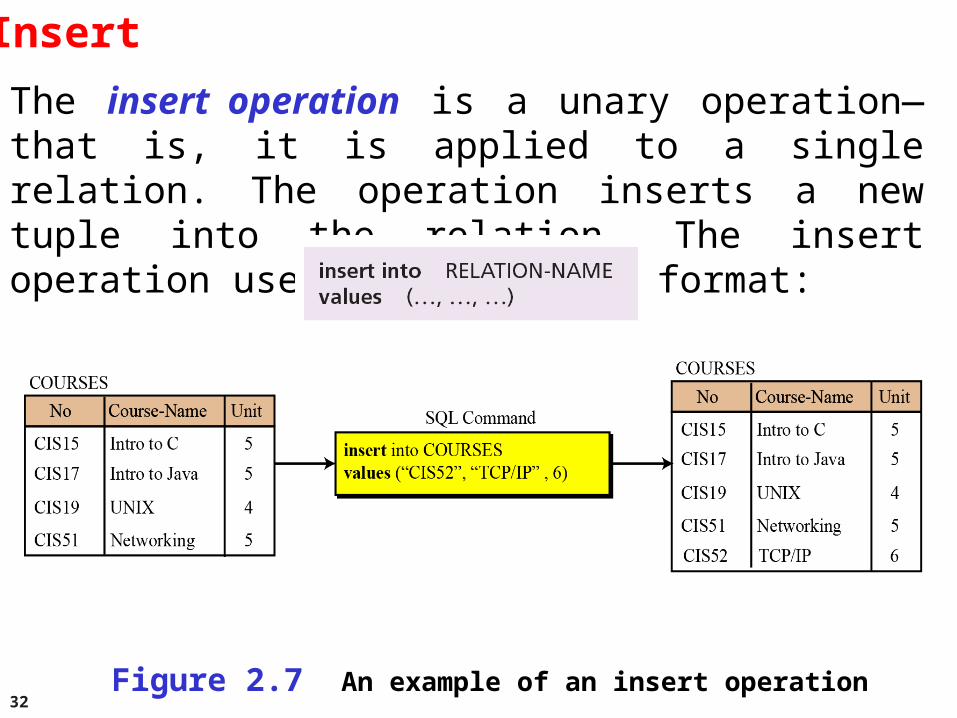
Insert
The insert operation is a unary operation—that is, it is applied to a single relation. The operation inserts a new tuple into the relation. The insert operation uses the following format:
Figure 2.7 An example of an insert operation
33
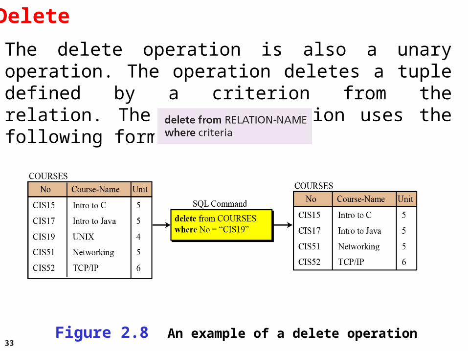
Delete
The delete operation is also a unary operation. The operation deletes a tuple defined by a criterion from the relation. The delete operation uses the following format:
Figure 2.8 An example of a delete operation
34
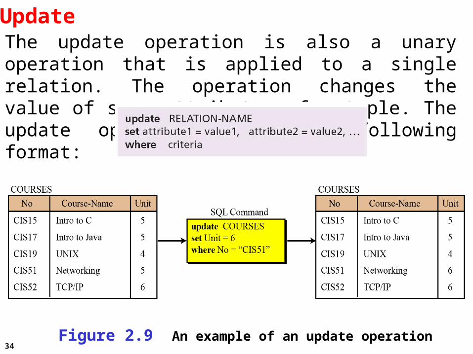
UpdateThe update operation is also a unary operation that is applied to a single relation. The operation changes the value of some attributes of a tuple. The update operation uses the following format:
Figure 2.9 An example of an update operation
35
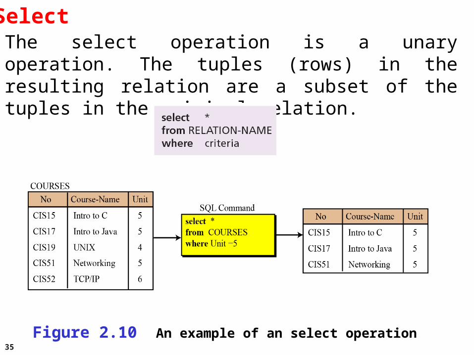
SelectThe select operation is a unary operation. The tuples (rows) in the resulting relation are a subset of the tuples in the original relation.
Figure 2.10 An example of an select operation
36
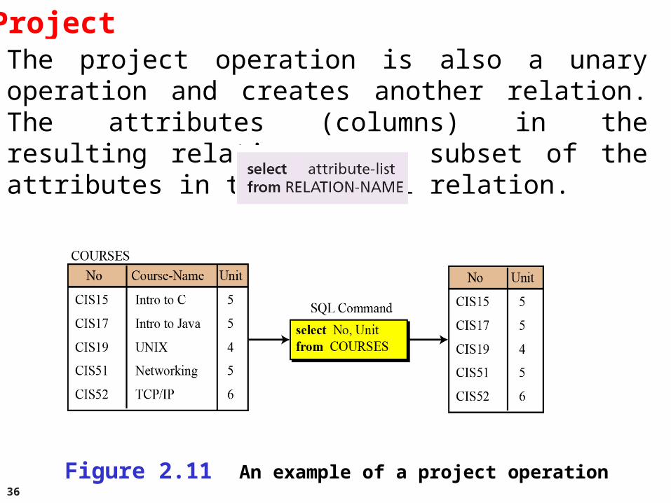
ProjectThe project operation is also a unary operation and creates another relation. The attributes (columns) in the resulting relation are a subset of the attributes in the original relation.
Figure 2.11 An example of a project operation
37
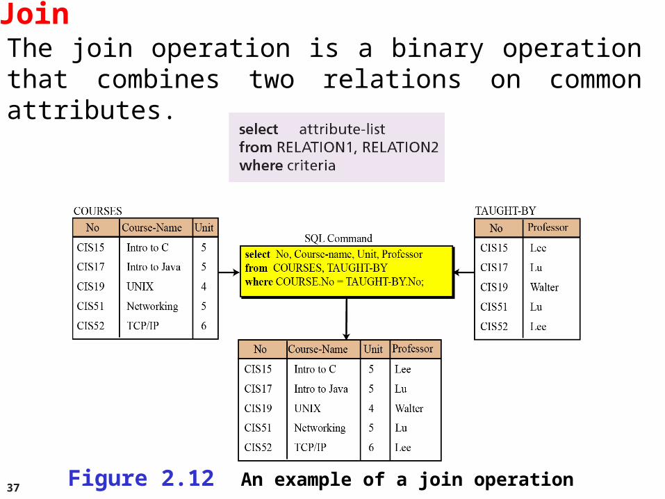
JoinThe join operation is a binary operation that combines two relations on common attributes.
Figure 2.12 An example of a join operation
38
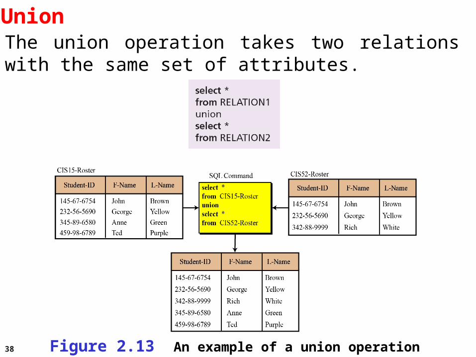
UnionThe union operation takes two relations with the same set of attributes.
Figure 2.13 An example of a union operation
39
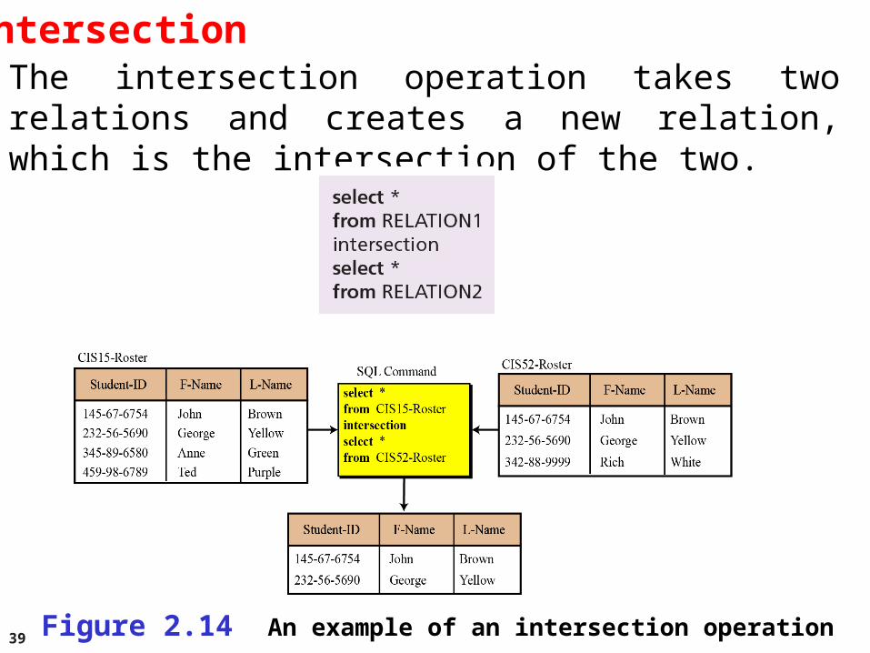
IntersectionThe intersection operation takes two relations and creates a new relation, which is the intersection of the two.
Figure 2.14 An example of an intersection operation
40
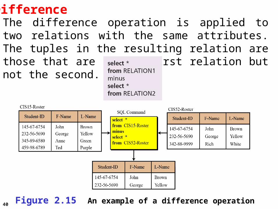
DifferenceThe difference operation is applied to two relations with the same attributes. The tuples in the resulting relation are those that are in the first relation but not the second.
Figure 2.15 An example of a difference operation
41
2-9 DATABASE DESIGN2-9 DATABASE DESIGN
The design of any database is a lengthy and involved The design of any database is a lengthy and involved task that can only be done through a step-by-step task that can only be done through a step-by-step process. The first step normally involves interviewing process. The first step normally involves interviewing potential users of the database. The second step is to potential users of the database. The second step is to build an build an entity-relationship model (ERM)entity-relationship model (ERM) that defines that defines the entities, the attributes of those entities and the the entities, the attributes of those entities and the relationship between those entities.relationship between those entities.
42
Entity-relationship models (ERM)
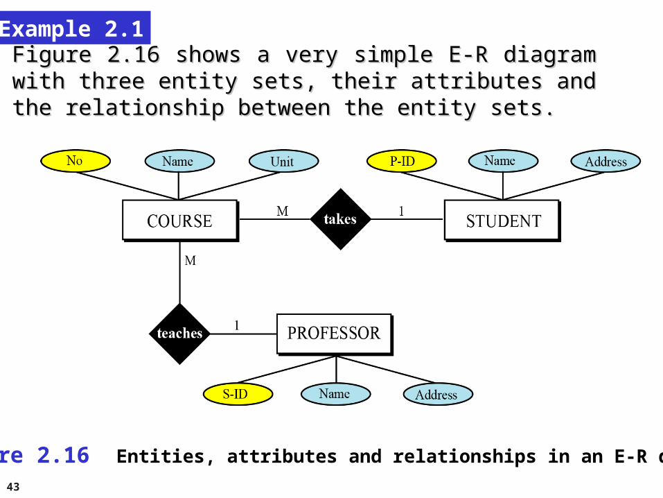
In this step, the database designer creates an entity-relationship (E-R) diagram to show the entities for which information needs to be stored and the relationship between those entities. E-R diagrams uses several geometric shapes, but we use only a few of them here:
❑ Rectangles represent entity sets
❑ Ellipses represent attributes
❑ Diamonds represent relationship sets
Lines link attributes to entity sets and link entity sets to relationships sets
43
Example 2.1
Figure 2.16 shows a very simple E-R diagram with three entity Figure 2.16 shows a very simple E-R diagram with three entity sets, their attributes and the relationship between the entity sets.sets, their attributes and the relationship between the entity sets.
Figure 2.16 Entities, attributes and relationships in an E-R diagram
44
From E-R diagrams to relationsAfter the E-R diagram has been finalized, relations (tables) in the relational database can be created.
Relations for entity setsFor each entity set in the E-R diagram, we create a relation (table) in which there are n columns related to the n attributes defined for that set.
45
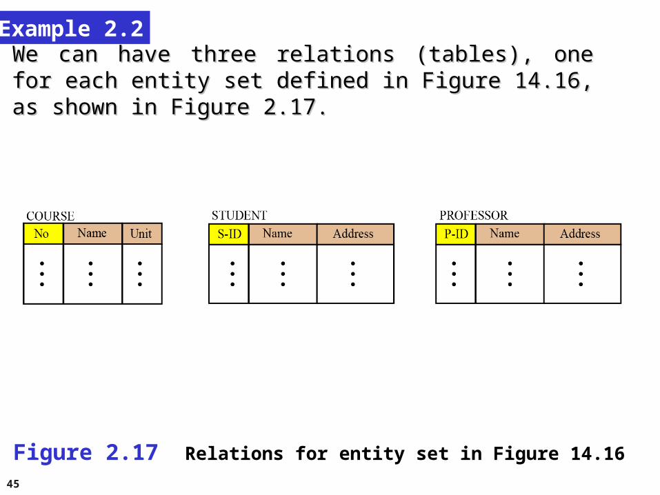
Example 2.2
We can have three relations (tables), one for each entity set We can have three relations (tables), one for each entity set defined in Figure 14.16, as shown in Figure 2.17.defined in Figure 14.16, as shown in Figure 2.17.
Figure 2.17 Relations for entity set in Figure 14.16
46
Relations for relationship sets
For each relationship set in the E-R diagram, we create a relation (table). This relation has one column for the key of each entity set involved in this relationship and also one column for each attribute of the relationship itself if the relationship has attributes (not in our case).
47
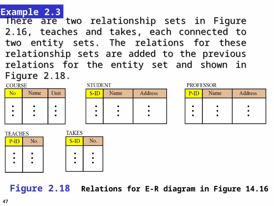
Example 2.3
There are two relationship sets in Figure 2.16, teaches and takes, There are two relationship sets in Figure 2.16, teaches and takes, each connected to two entity sets. The relations for these each connected to two entity sets. The relations for these relationship sets are added to the previous relations for the entity relationship sets are added to the previous relations for the entity set and shown in Figure 2.18.set and shown in Figure 2.18.
Figure 2.18 Relations for E-R diagram in Figure 14.16
48
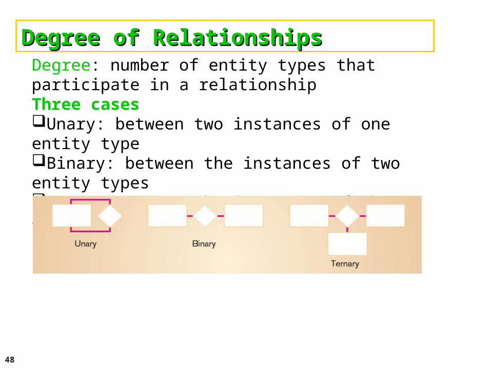
Degree of RelationshipsDegree of RelationshipsDegree: number of entity types that participate in a relationship Three cases Unary: between two instances of one entity type Binary: between the instances of two entity types Ternary: among the instances of three entity types
49
Relationships can be classified as eitherRelationships can be classified as either one-to-one (1:1) one-to-many (1:N) many-to-many (N:M)
(1:1) The relationship HEAD-OF between entity types MANAGER and DEPARTMENT. This means that a department has at most one head and that a manager is head of at most one department. (1:N) The relationship SUPERVISES between the entity types MANAGER and EMPLOYEE. This assumes that a manager may supervise any number of different employees but a given employee is supervised by at most one manager.
50
Relationships can be classified as either
(N:M) The relationship ASSIGNED-TO between the entity types EMPLOYEE and PROJECT. An employee may be assigned to many different projects and each project may have many employees assigned to it.
Simple Hospital System In a hospital system, each ward has many patients who are cared for by nurses assigned to the ward. Patients may require treatment by more than one specialist doctor. Draw an ERD for the simple hospital system.?
Example 2.4
51
NormalizationNormalization is the process by which a given set of relations are transformed to a new set of relations with a more solid structure. Normalization is needed to allow any relation in the database to be represented, to allow a language like SQL to use powerful retrieval operations composed of atomic operations, to remove anomalies in insertion, deletion, and updating, and reduce the need for restructuring the database as new data types are added.The normalization process defines a set of hierarchical normal forms (NFs). Several normal forms have been proposed, including 1NF, 2NF, 3NF, BCNF (Boyce-Codd Normal Form), 4NF, PJNF (Projection/Joint Normal Form), 5NF and so on.
52
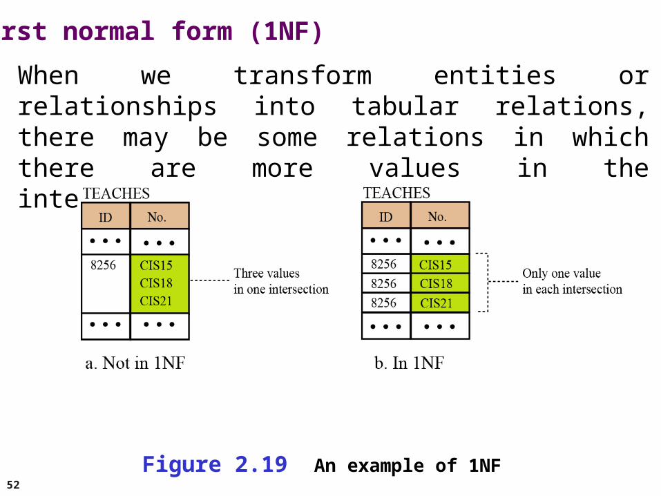
First normal form (1NF)
When we transform entities or relationships into tabular relations, there may be some relations in which there are more values in the intersection of a row or column.
Figure 2.19 An example of 1NF
53
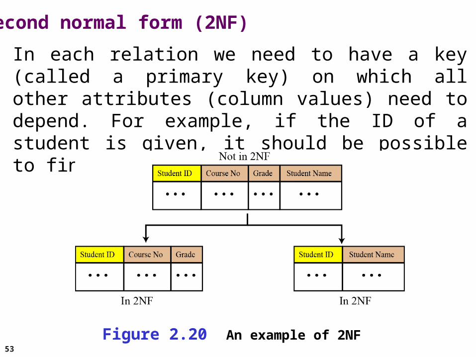
Second normal form (2NF)
In each relation we need to have a key (called a primary key) on which all other attributes (column values) need to depend. For example, if the ID of a student is given, it should be possible to find the student’s name.
Figure 2.20 An example of 2NF
54
Other normal forms
Other normal forms use more complicated dependencies among attributes. We leave these dependencies to books dedicated to the discussion of database topics.
55
2-10 OTHER DATABASE MODELS2-10 OTHER DATABASE MODELS
The relational database is not the only database model The relational database is not the only database model in use today. Two other common models are in use today. Two other common models are distributed databasesdistributed databases and and object-oriented databasesobject-oriented databases. . We briefly discuss these here.We briefly discuss these here.
56
Distributed databases
The distributed database model is not a new model, but is based on the relational model. However, the data is stored on several computers that communicate through the Internet or a private wide area network. Each computer (or site) maintains either part of the database or the whole database.
Fragmented distributed databases
In a fragmented distributed database, data is localized—locally used data is stored at the corresponding site. However, this does not mean that a site cannot access data stored at another site. Access is mostly local, but occasionally global.
57
Replicated distributed databases
In a replicated distributed database, each site holds an exact replica of another site. Any modification to data stored in one site is repeated exactly at every site. The reason for having such a database is security. If the system at one site fails, users at the site can access data at another site.
58
Object-oriented databases
An object-oriented database tries to keep the advantages of the relational model and at the same time allows applications to access structured data. In an object-oriented database, objects and their relations are defined. In addition, each object can have attributes that can be expressed as fields.
XMLThe query language normally used for objected-oriented databases is XML (Extensible Markup Language). As we discussed in Chapter 6, XML was originally designed to add markup information to text documents, but it has also found its application as a query language in databases. XML can represent data with nested structures.