Embed Size (px)
Citation preview
1
Data Link LayerData Link LayerLecture 20Lecture 20
Imran AhmedImran AhmedUniversity of Management & TechnologyUniversity of Management & Technology

2
Agenda
• Introduction & services
• Error detection and correction
• Multiple access protocols
• LAN addresses and ARP
• Ethernet
• Hubs, bridges and switches
3
Introduction
• Data Link layer has responsibility of transferring datagram from one node to adjacent node over a link.

4
Link Layer Services
• Framing, link access:– Encapsulate datagram into frame, adding header, trailer
– Channel access if shared medium
– ‘Physical addresses’ used in frame headers to identify source, destination
• Flow Control:– Pacing between adjacent sending and receiving nodes
• Error Detection:– Errors caused by signal attenuation, noise
– Receiver detects presence of errors:• Signals sender for re-transmission or drops frame

5
Link Layer Services (more)
• Error Correction:– Receiver identifies and corrects bit error(s)
without resorting to re-transmission
• Half-duplex & full-duplex:– With half-duplex, nodes at both ends of link can
transmit, but not at same time

6
Agenda
• Introduction & services
• Error detection and correction
• Multiple access protocols
• LAN addresses and ARP
• Ethernet
• Hubs, bridges and switches
7
Error Detection & Correction• Data can be corrupted during transmission,
for reliable communication, errors must be detected and corrected.
• Error detection and correction are implemented either at the data link layer or the transport layer of the OSI model.
8
Types of Errors
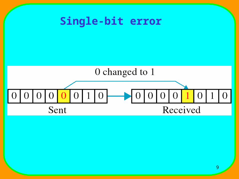
• There are two types of errors:-– Single-Bit Error: means that only one bit of a
given data unit is changed from 1 to 0 or from 0 to 1.• A single-bit error can happen usually if we are sending data
using parallel transmission.
– Burst Error: means two or more bits in the data unit have changed from 1 to 0 or from 0 to 1.
• Burst error is most likely to happen in a serial transmission.
9
Single-bit error

10
Burst error
11
Error Detection
• Error detection uses the concept of redundancy, which means adding extra bits for detecting errors at the destination.
• Three types of redundancy checks are used:-– Vertical Redundancy Check (Parity Check)
– Cyclic Redundancy Check (CRC)
– Checksum
12
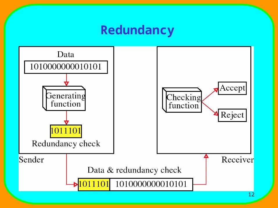
Redundancy
13
Vertical Redundancy Check
• The most common and least expensive mechanism for error detection is the vertical redundancy check (VRC), often called a parity check.
• In this technique, a redundant bit called a parity bit, is appended to every data unit so that the total number of 1’s in the unit (including the parity bit) becomes even.

14
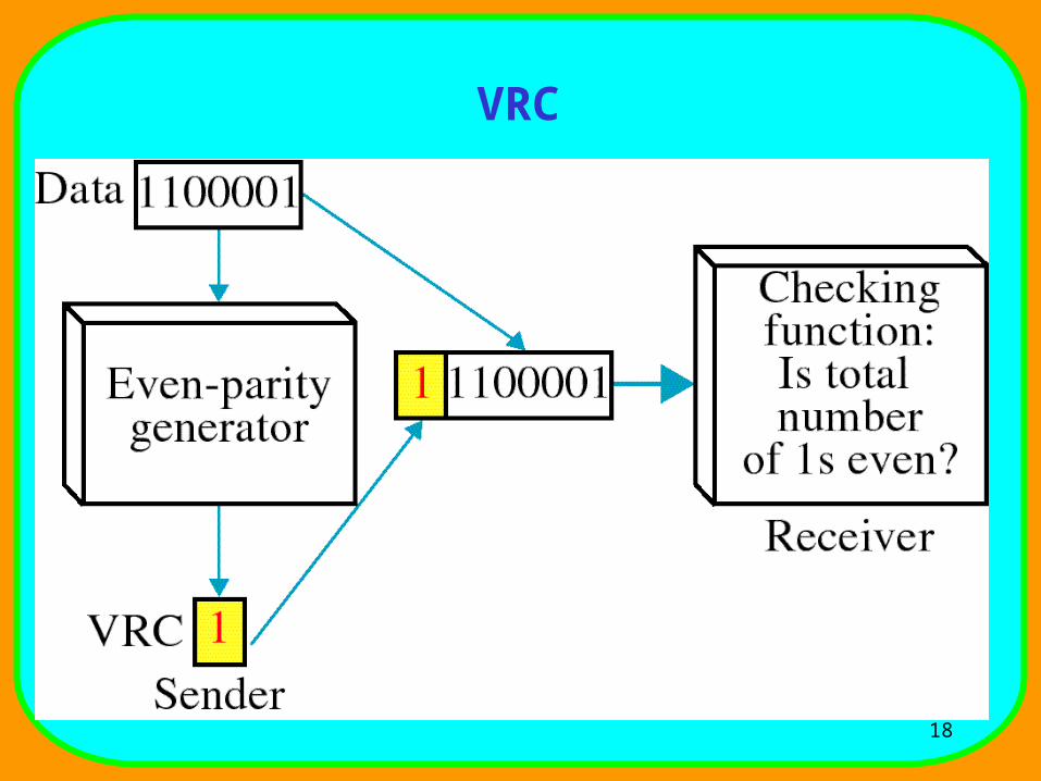
Vertical Redundancy Check (more)• Suppose we want to transmit the binary data unit 1100001.
Counting together the number of 1’s gives us three, an odd number. Before transmitting, we pass the data unit through a parity generator.
• The parity generator counts the 1’s and appends the parity bit to the end. The total number of 1’s is now four, an even number.
• The system now transmits the entire expanded unit across the network link. When it reaches its destination, the receiver puts all eight bits through an even-parity checking function.
15
Vertical Redundancy Check (more)• If the receiver sees 11100001, it counts four 1’s,
an even number and the data unit passes. But if the data unit has been damaged in transit, what if, instead of 11100001, the receiver sees 11100101?
• Then the parity checker counts the 1’s, it gets 5’s, an odd number. The receiver knows that an error has been introduced into the data somewhere and therefore rejects the whole unit.
16
Vertical Redundancy Check
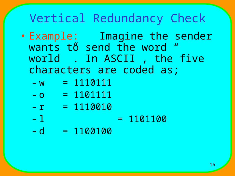
• Example: Imagine the sender wants to send the word “ world ”. In ASCII , the five characters are coded as;– w = 1110111– o = 1101111– r = 1110010– l = 1101100– d = 1100100
17
Vertical Redundancy Check
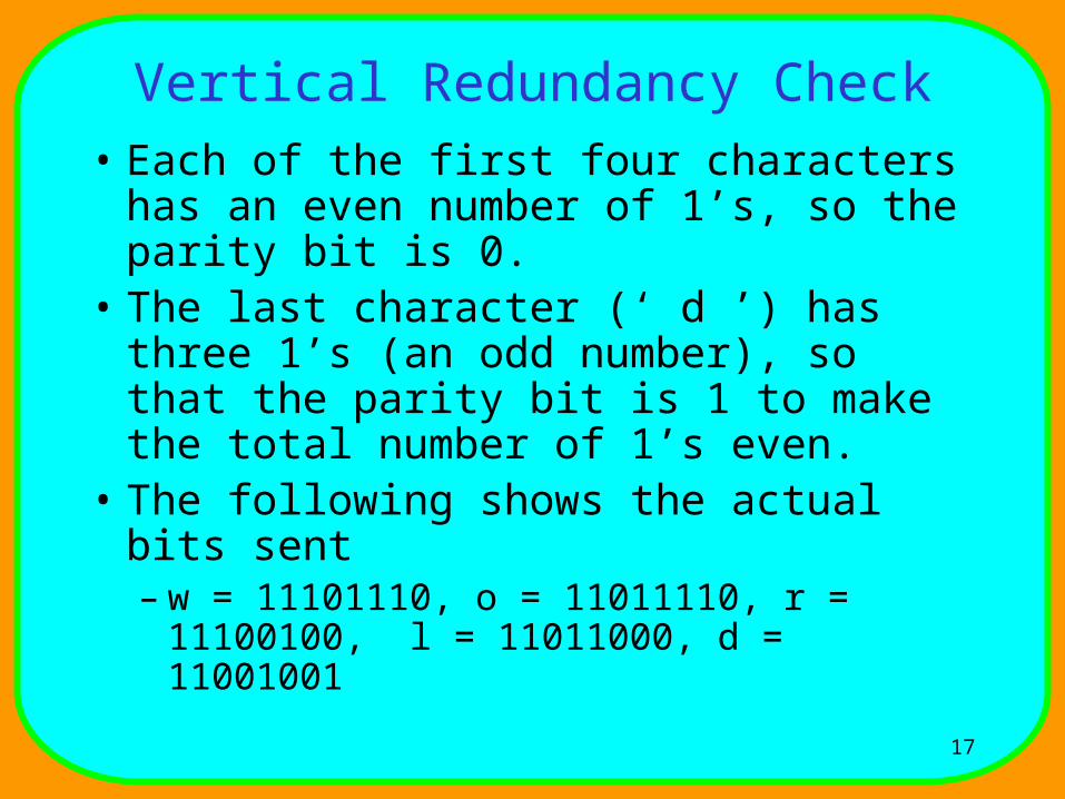
• Each of the first four characters has an even number of 1’s, so the parity bit is 0.
• The last character (‘ d ’) has three 1’s (an odd number), so that the parity bit is 1 to make the total number of 1’s even.
• The following shows the actual bits sent– w = 11101110, o = 11011110, r = 11100100, l
= 11011000, d = 11001001
18
VRC
19
Vertical Redundancy Check• Performance:
– VRC can detect all single-bit errors.– It can also detect burst errors as long as the total
number of bits changed is odd (1, 3, 5, etc.).– Suppose, however, that two bits of the data unit are
changed, in this case the number of 1’s in the data unit is still even. The VRC checker will add them and return an even number although the data unit contains two errors.
– VRC cannot detect errors where the total number of bits changed, is even.

20
Cyclic Redundancy Check• The second and the most powerful technique for
redundancy checking is CRC.• Unlike, VRC, which is based on addition, CRC is
based on binary division.• In CRC, instead of adding bits together to achieve
a desired parity, a sequence of redundant bits, called the CRC or the CRC remainder, is appended to the end of a data unit so that the resulting data unit becomes exactly divisible by a second predetermined binary number.
• At its destination, the incoming data unit is divided by the same number. If at this step, there is no remainder, means no errors and if there is a remainder, means errors.
21
Cyclic Redundancy Check
• The redundancy bits used by CRC are derived by dividing the data unit by a predetermined divisor; the remainder is the CRC. To be valid, a CRC must have two qualities:– It must have exactly one less bit than the divisor, and
appending it to the end of the data string must make the resulting bit sequence exactly divisible by the divisor.
22
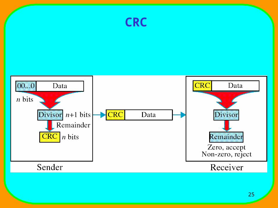
Cyclic Redundancy Check• CRC provides an outline of the three basic steps:-
– First, a string of n 0’s is appended to the data unit. The number n is one less than the number of bits in the predetermined divisor, which is n + 1 bits.
– Second, the newly elongated data unit is divided by the divisor using a process called binary division. The remainder resulting from this division is the CRC.
– Third, the CRC of n bits derived in step 2 replaces the appended 0’s at the end of the data unit.
23
Cyclic Redundancy Check• The data unit arrives at the receiver, where data
comes first, followed by the CRC. The receiver treats the whole string as a unit and divides it by the same divisor that was used to find the CRC remainder.
• If the string arrives without error, the CRC checker yields a remainder of zero and the data unit passes. If the string has been changed in transit, the division yields a non-zero remainder and the data unit does not pass.
24
Cyclic Redundancy Check• CRC Generator: A CRC generator uses modulo-
2 division. (as shown in figure)• CRC Checker: A CRC checker functions
exactly like the generator. After receiving the data appended with the CRC, it does the same modulo-2 division. If the remainder is all 0’s, the CRC is dropped and the data accepted; otherwise, the received stream of bits is discarded and data are resent.
25
CRC

26
Binary Division

27
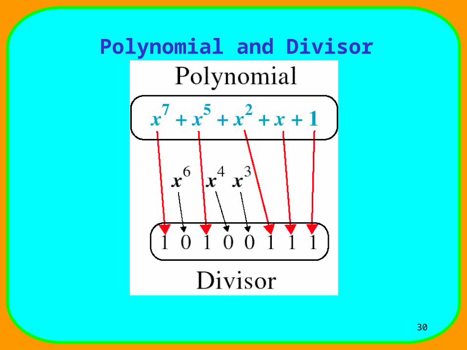
Cyclic Redundancy Check
• Polynomials: The CRC generator (the divisor) is most often represented not as a string of 1’s and 0’s, but as an algebraic polynomials. The polynomial format is useful for two reasons:-– It is short– It can be used to prove the concept
mathematically

28
Polynomial
29
Cyclic Redundancy Check
• A polynomial should be selected to have at least the following properties:– It should not be divisible by x.– It should be divisible by (x + 1).
30
Polynomial and Divisor
31
Standard Polynomials
32
Cyclic Redundancy Check• Performance: CRC is very effective error
method. If the divisor is chosen according to the previously mentioned rules– CRC can detect all burst errors that affect an odd
number of bits.– CRC can detect all burst errors of length less than or
equal to the degree of the polynomial.– CRC can detect with a very high probability burst
errors of length greater than the degree of the polynomials.
33
Checksum
• Checksum Generator:– In the sender, the checksum generator subdivides the
data unit into equal segments of n bits (usually 16).
– These segments are added together using one’s compliment arithmetic in such a way that the total is also n bits long.
– That total (sum) is then complemented and appended to the end of the original data unit as redundancy bits, called the checksum field.
34
Checksum
• So the sender follows these steps:-– The unit is divided into k sections, each of n
bits.– All sections are added together using one’s
complement to get the sum.– The sum is complemented and becomes the
checksum.– The checksum is sent with the data.

35
Checksum
• Checksum Checker:– The receiver subdivides the data unit as above
and adds all segments together and complements the result.
– If the extended data unit is intact, the total value found by adding the data segments and the checksum field should be zero.
– If the result is not zero, the packet contains an error and the receiver rejects it.
36
Checksum
• The receiver must follows these steps:– The unit is divided into k sections, each of n
bits.– All sections are added together using one’s
complement to get the sum.– The sum is complemented.– If the result is zero, the data are accepted:
otherwise, they are rejected.

37
Checksum
• Example: Suppose the following block of 16 bits is to be sent using a checksum of 8 bits, 10101001 00111001 The numbers are added using one’s complement arithmetic: 10101001
00111001
Sum 11100010
Checksum 00011101
38
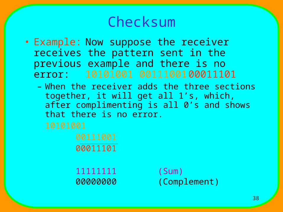
Checksum• Example: Now suppose the receiver receives
the pattern sent in the previous example and there is no error: 10101001 00111001 00011101– When the receiver adds the three sections together, it
will get all 1’s, which, after complimenting is all 0’s and shows that there is no error.
101010010011100100011101
11111111 (Sum)00000000 (Complement)

39
Checksum
• Performance:– Checksum detests all errors involving an odd number
of bits, as well as most errors involving an even number of bits.
– However, if one or more bits of a segment are damaged and the corresponding bit or bits of opposite value in a second segment are also damaged, the sums of those columns will not change and the receiver will not detect a problem.