Embed Size (px)
Citation preview

1
Circuit Partitioning
Presented by Jill

2
Outline
Introduction Cut-size driven circuit partitioning Multi-objective circuit partitioning Our approach – Network flow based
Methodology Difficulties

3
Introduction
What is circuit partitioning ? Circuit partitioning is vital
Complexity increases Number of transistors involved increases Chip size decreases
Partitioning objective Cut-size Delay

4
Cut-Size Driven Approach

5
Cut-Size Driven Approach
“Multilevel Hypergraph Partitioning: Application in VLSI Domain”
G.Karypis, R.Aggarwal, V.Kumar, S.Shekhar. DAC 1997
Multilevel hypergraph partitioning algorithm – hMetis

6
Cut-Size Driven Approach
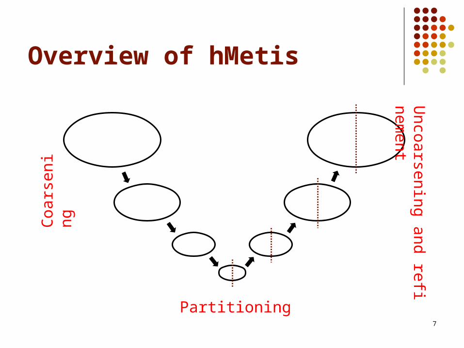
Three phases: Coarsening Phase Partitioning Phase Uncoarsening and Refinement Phase
7
Overview of hMetisC
oars
enin
gU
ncoarsening and refinementPartitioning

8
Coarsening
Edge Coarsening
Hyperedge Coarsening
Modified Hyperedge Coarsening

9
Uncoarsening and Refinement
Successively projecting the partitioning to the next level
Refinement: Early-exit FM
Max. number of pass = 2 In each pass, if no improvement after k move, exit
Hyperedge Refinement Remove an entire hyperedge from the cut

10
Multi - Objective Approach

11
Multi-Objective Approach
“Multi-objective Circuit Partitioning for Cutsize and Path-Based Delay Minimization” C.Ababei, N.Selvakkumaran, K.Bazargan, G.Karypis ICCAD 2002
Multi-objective circuit partitioning based on hMetis Minimize cut-size Minimize delay

12
Multi-Objective Approach
Good solution Allow fine-tuned control of the objectives Provide way to handle objectives of different
natures Two main differences Objective function
Soln = p1*C + p2*D

13
Multi-Objective Approach
Delay Delay of the critical path # of cut along each critical path Edge weight of all edges that lie on the critical
path

14
K-Most Critical Paths
Partitioning without updating the K-most critical paths
Update the list of the K-most critical paths during each move
How to choose K? Small no improvement Large run time increase, solution space
decrease

15
Improvement Over hMetis
Delay 14 % decrease Cut-size 10% increase Run-time 2.4x

16
Network Flow Based Approach
17
Network Flow Based Approach
Originated by Eric Wong, Prof. Young Delay driven K-way partitioning Three phase:
Net modelling Partitioning phase Refinement phase

18
Net Modelling
As network flow technique is used, circuits should be modelled as graph
Acyclic partitioning for the following paths: PI PO PI FF FF FF FF PO

19
Net modelling
Combinational net
Two-terminal Net:
Multi-terminal Net:
1
V I
8
1
I
J
V
8 8
8 8
V I
J
V I

20
Net Modelling
Sequential Net
ff
w1
w2
d1 d2
w1
w2
1
8
8
88
88
ff

21
Partitioning Phase
Max-Flow Min-Cut Guarantee min-cut Not necessarily balanced
“Efficient Network Flow Based Min-Cut Balanced Partitioning” Honghua Yang, D.F. Wong ICCAD 1994

22
Partitioning Phase

23
Partitioning Phase
How to select from the larger partition ? If > threshold
Random select If < threshold
Try all possible choices Follow acyclic constraint Apply the partitioning phase recursively to
obtain k-way partitioning
24
Refinement Phase
FM post-processing step Apply FM to every pair of partition Different from original FM
If delay increased, reject May yield cyclic result

25
Experimental results
1to2.xls 1to5.xls

26
Difficuties
Possible reason: Ratio increased % decreased Method of bipartitioning Acyclic restriction
Future Direction Cyclic ? Acyclic ?