Embed Size (px)
Citation preview

ChecklistsChecklistsChecklists
A320 (FOR SIMULATION ONLY)
a320.tcsims.com
© True Course Simulations 2015

1/33 ©2015 True Course Simulations
Introduction This document contains three main sections:
1. Normal Checklist 2. Normal Checklist Explanation 3. Standard Operating Procedures Amplified (SOPA)
1. Normal Checklist The flight crew uses the checklist (pages 3-4) on every flight and for every phase of flight for which a checklist has been established. 2. Normal Checklist Explanation The Normal Checklist Explanation (pages 6-16) provides a detailed explanation of individual items of the Normal Checklist where needed. Checklist Usage Before using the checklist, each crewmember configures the controls and
systems in accordance with the appropriate SOPA flow pattern. Crewmembers use the checklist to verify switch or system configuration only
after the flight deck has been set up or a flow pattern accomplished. The checklist functions as a “check” list, not a “do” list. The philosophy is to accomplish the flow pattern at the appropriate time. When the checklist is called for, read each checklist item and verify switch or
system configuration. When reading the checklist, the crew will progress to the next item only after the
pilot responding visually confirms the proper switch position or system configuration.
The SECURING CHECK is the only exception to the “do” and “check” philosophy. The items on this checklist are not performed as part of a flow pattern. The SECURING CHECK is used as a “read and do” checklist.
The crewmember indicated at the top of the left column will read the checklist.
The crewmember indicated at the top of the right column will respond to the checklist.
Items that require a response from a specific crewmember will identify the responding individual: Captain (C), First Officer (FO), Pilot Flying (PF), Pilot Monitoring (PM), and (BOTH) for both Pilots.
To reduce distraction, some checklist items are read and verified silently. These items are identified with a bracket [ ] around the response.
Use the specific wording of each challenge and response for all normal situations.
When an item allows a choice of responses, such as Engine Anti-Ice - OFF (ON), the choices are listed and the appropriate response should be given.
Where a blank “____” appears in the challenge or response, use the actual value (Example “Altimeters.....29.82 IN”).
2/33 ©2015 True Course Simulations
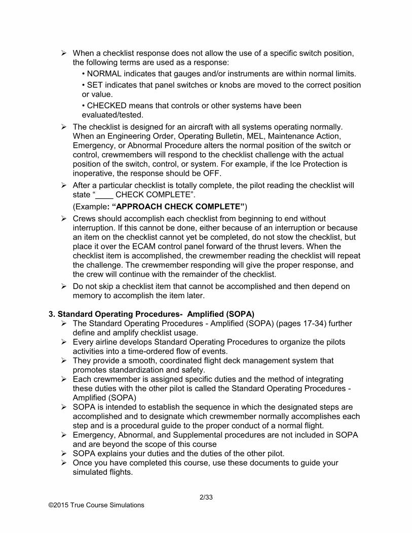
When a checklist response does not allow the use of a specific switch position, the following terms are used as a response:
• NORMAL indicates that gauges and/or instruments are within normal limits.
• SET indicates that panel switches or knobs are moved to the correct position or value.
• CHECKED means that controls or other systems have been evaluated/tested.
The checklist is designed for an aircraft with all systems operating normally. When an Engineering Order, Operating Bulletin, MEL, Maintenance Action, Emergency, or Abnormal Procedure alters the normal position of the switch or control, crewmembers will respond to the checklist challenge with the actual position of the switch, control, or system. For example, if the Ice Protection is inoperative, the response should be OFF.
After a particular checklist is totally complete, the pilot reading the checklist will state “____ CHECK COMPLETE”.
(Example: “APPROACH CHECK COMPLETE”)
Crews should accomplish each checklist from beginning to end without interruption. If this cannot be done, either because of an interruption or because an item on the checklist cannot yet be completed, do not stow the checklist, but place it over the ECAM control panel forward of the thrust levers. When the checklist item is accomplished, the crewmember reading the checklist will repeat the challenge. The crewmember responding will give the proper response, and the crew will continue with the remainder of the checklist.
Do not skip a checklist item that cannot be accomplished and then depend on memory to accomplish the item later.
3. Standard Operating Procedures- Amplified (SOPA) The Standard Operating Procedures - Amplified (SOPA) (pages 17-34) further
define and amplify checklist usage. Every airline develops Standard Operating Procedures to organize the pilots
activities into a time-ordered flow of events. They provide a smooth, coordinated flight deck management system that
promotes standardization and safety. Each crewmember is assigned specific duties and the method of integrating
these duties with the other pilot is called the Standard Operating Procedures - Amplified (SOPA)
SOPA is intended to establish the sequence in which the designated steps are accomplished and to designate which crewmember normally accomplishes each step and is a procedural guide to the proper conduct of a normal flight.
Emergency, Abnormal, and Supplemental procedures are not included in SOPA and are beyond the scope of this course
SOPA explains your duties and the duties of the other pilot. Once you have completed this course, use these documents to guide your
simulated flights.
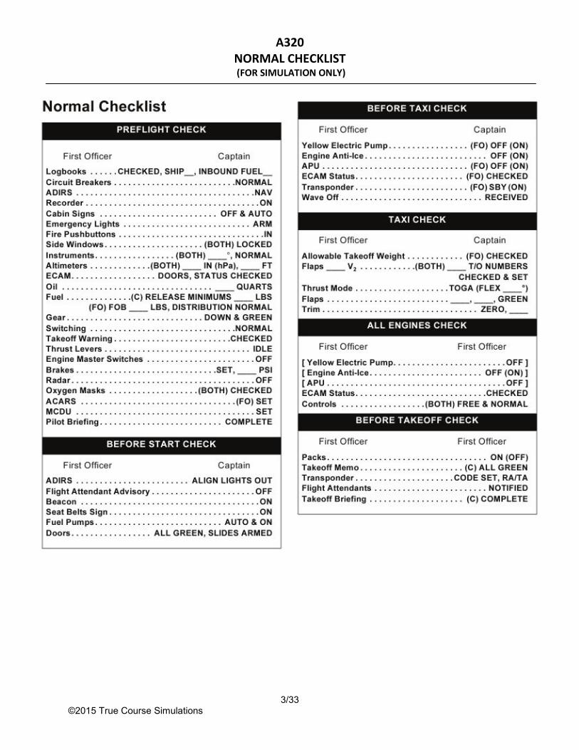
A320 NORMAL CHECKLIST (FOR SIMULATION ONLY)
3/33 ©2015 True Course Simulations

A320 NORMAL CHECKLIST (FOR SIMULATION ONLY)
4/33 ©2015 True Course Simulations

A320 NORMAL CHECKLIST EXPLANATION
(FOR SIMULATION ONLY)
5/33 ©2015 True Course Simulations
PREFLIGHT CHECK
NOTE: The crew must accomplish the complete PREFLIGHT CHECK before every flight. FIRST OFFICER CAPTAIN Logbooks. . . . . . . . . . . . . . . . . . . . . . . . . . . . . . . . . . . . . . CHECKED, SHIP____, INBOUND FUEL____
CHECKED means that the Captain has reviewed both the Aircraft and Flight Attendant Maintenance logs and verified: That the ship number on the cover of each logbook agrees with the number on the Dispatch
Release and the aircraft. That all open logbook write-ups have been resolved. That Minimum Equipment List and Configuration Deviation List items indicated by the
placards in the logbook are included on the Dispatch Release. The Captain will state the aircraft ship number and the inbound fuel total as determined from
the previous flight entry on the arrival fuel column of the logbook. Circuit Breakers . . . . . . . . . . . . . . . . . . . . . . . . . . . . . . . . . . . . . . . . . . . . . . . . . . . . . . . . . . . . . .NORMAL
Ensure that all collared Circuit Breakers are appropriate for the MEL status of the aircraft. ADIRS. . . . . . . . . . . . . . . . . . . . . . . . . . . . . . . . . . . . . . . . . . . . . . . . . . . . . . . . . . . . . . . . . . . . . . . . . . .NAV Recorder . . . . . . . . . . . . . . . . . . . . . . . . . . . . . . . . . . . . . . . . . . . . . . . . . . . . . . . . . . . . . . . . . . . . . . . . . ON
If the RCDR was OFF when the PREFLIGHT CHECK was started, select it ON and restart the checklist.
Cabin Signs. . . . . . . . . . . . . . . . . . . . . . . . . . . . . . . . . . . . . . . . . . . . . . . . . . . . . . . . . . . . . . . . . OFF & ON The SEAT BELTS switch is in the OFF position and the NO SMOKING switch is in the ON
position. Emergency Lights. . . . . . . . . . . . . . . . . . . . . . . . . . . . . . . . . . . . . . . . . . . . . . . . . . . . . . . . . . . . . . . . .ARM Fire Pushbuttons . . . . . . . . . . . . . . . . . . . . . . . . . . . . . . . . . . . . . . . . . . . . . . . . . . . . . . . . . . . . . . . . . . . IN Side Windows. . . . . . . . . . . . . . . . . . . . . . . . . . . . . . . . . . . . . . . . . . . . . . . . . . . . . . . . . .(BOTH) LOCKED
Ensure that the side windows are closed, the handles are fully outboard, and the red rings are visible.
Instruments. . . . . . . . . . . . . . . . . . . . . . . . . . . . . . . . . . . . . . . . . . . . . . . . . . . . . .(BOTH) ____°, NORMAL Respond with the heading in degrees that is displayed on the PFD and ND. NORMAL indicates that the PFD, ND, DDRMI, standby attitude indicator and standby altimeter
are fully operational and have no abnormal flags, the FMA has been checked and both FDs are ON and normal (1FD2).
Altimeters. . . . . . . . . . . . . . . . . . . . . . . . . . . . . . . . . . . . . . . . . . . . . . . . . .(BOTH) ____ IN ____ FT Respond with the altimeter setting in inches as provided by the local facility, and the MSL
altitude is set on the PFD. Ensure the PFD altitudes displayed are both within 25’ of each other and 75’ of the field
elevation. The Captain also ensures the standby altimeter is set and within 300’ of field elevation.
ECAM. . . . . . . . . . . . . . . . . . . . . . . . . . . . . . . . . . . . . . . . . . . . . . . . . . . . . . .DOORS, STATUS CHECKED The ECAM panel is in a lights out configuration and the DOOR/OXY page is displayed.
Oil. . . . . . . . . . . . . . . . . . . . . . . . . . . . . . . . . . . . . . . . . . . . . . . . . . . . . . . . . . . . . . . . . . . . . .____ QUARTS Respond with the lowest engine oil quantity that was noted during the preflight of the ECAM
ENG page. Fuel . . . . . . . . . . . . . . . . . . . . . . . . . . . . . . . . . . . . . . . . . . . . . . . . . . (C) RELEASE MINIMUMS ____ LBS
The Captain will state the minimum release fuel as specified on the dispatch release. (FO) FOB ____ LBS, DISTRIBUTION NORMAL

A320 NORMAL CHECKLIST EXPLANATION
(FOR SIMULATION ONLY)
5/33 ©2015 True Course Simulations
Each crewmember’s response also indicates that the fuel slip is on board the aircraft and has been checked for accuracy.
It also means that the actual fuel load and distribution have been checked on the ECAM FUEL page and compared with the flight plan/dispatch release fuel.
The crew has verified that the fuel quantity on board is adequate to complete the flight. The First Officer’s response is made with reference to the actual upper ECAM FOB figure.
Gear . . . . . . . . . . . . . . . . . . . . . . . . . . . . . . . . . . . . . . . . . . . . . . . . . . . . . . . . . . . . . . . . . DOWN & GREEN Ensure that the landing gear lever is down and that the indicator panel shows three green
lights. Switching. . . . . . . . . . . . . . . . . . . . . . . . . . . . . . . . . . . . . . . . . . . . . . . . . . . . . . . . . . . . . . . . . . . .NORMAL Takeoff Warning . . . . . . . . . . . . . . . . . . . . . . . . . . . . . . . . . . . . . . . . . . . . . . . . . . . . . . . . . . . . .CHECKED
CHECKED indicates that the T.O CONFIG pb on the ECAM control panel has been pressed and the takeoff warning was triggered.
The red SLATS/ FLAPS NOT IN T.O CONFIG messages were displayed on the upper ECAM along with the continuous repetitive chime and the red MASTER WARN lights.
Thrust Levers . . . . . . . . . . . . . . . . . . . . . . . . . . . . . . . . . . . . . . . . . . . . . . . . . . . . . . . . . . . . . . . . . . . .IDLE Engine Master Switches. . . . . . . . . . . . . . . . . . . . . . . . . . . . . . . . . . . . . . . . . . . . . . . . . . . . . . . . . . . . OFF Brakes . . . . . . . . . . . . . . . . . . . . . . . . . . . . . . . . . . . . . . . . . . . . . . . . . . . . . . . . . . . . . . . . . .SET, ____ PSI
The parking brake handle is in the ON position and the accumulator pressure is in the green band.
The Captain will respond with the lowest of the yellow system pressures as read on the gauges.
Radar . . . . . . . . . . . . . . . . . . . . . . . . . . . . . . . . . . . . . . . . . . . . . . . . . . . . . . . . . . . . . . . . . . . . . . . . . . . OFF Oxygen Masks. . . . . . . . . . . . . . . . . . . . . . . . . . . . . . . . . . . . . . . . . . . . . . . . . . . . . . . .(BOTH) CHECKED
CHECKED indicates that the mask and interphone are working properly and that the oxygen selector is in the 100% position.
The response “CHECKED” also indicates that the masks for the flight deck jumpseats (if occupied) have been checked.
ACARS. . . . . . . . . . . . . . . . . . . . . . . . . . . . . . . . . . . . . . . . . . . . . . . . . . . . . . . . . . . . . . . . . . . . . . (FO) SET The First Officer will verify that the Flight Data is programmed.
MCDU. . . . . . . . . . . . . . . . . . . . . . . . . . . . . . . . . . . . . . . . . . . . . . . . . . . . . . . . . . . . . . . . . . . . . . . . . . . SET The MCDU entries from the Captain’s & First Officer’s preflights have been accomplished.
Pilot Briefing. . . . . . . . . . . . . . . . . . . . . . . . . . . . . . . . . . . . . . . . . . . . . . . . . . . . . . . . . . . . . . . COMPLETE Verifies that the Pilot Briefing, to include a review of the general taxi plan, has been
accomplished.
Announce: “PREFLIGHT CHECK COMPLETE”
A320 NORMAL CHECKLIST EXPLANATION
(FOR SIMULATION ONLY)
5/33 ©2015 True Course Simulations
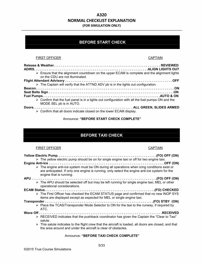
FIRST OFFICER CAPTAIN Release & Weather. . . . . . . . . . . . . . . . . . . . . . . . . . . . . . . . . . . . . . . . . . . . . . . . . . . . . . . . . . REVIEWED ADIRS. . . . . . . . . . . . . . . . . . . . . . . . . . . . . . . . . . . . . . . . . . . . . . . . . . . . . . . . . . . . . .ALIGN LIGHTS OUT
Ensure that the alignment countdown on the upper ECAM is complete and the alignment lights on the CDU are not illuminated.
Flight Attendant Advisory . . . . . . . . . . . . . . . . . . . . . . . . . . . . . . . . . . . . . . . . . . . . . . . . . . . . . . . . . . OFF The Captain will verify that the ATTND ADV pb is in the lights out configuration.
Beacon. . . . . . . . . . . . . . . . . . . . . . . . . . . . . . . . . . . . . . . . . . . . . . . . . . . . . . . . . . . . . . . . . . . . . . . . . . . ON Seat Belts Sign . . . . . . . . . . . . . . . . . . . . . . . . . . . . . . . . . . . . . . . . . . . . . . . . . . . . . . . . . . . . . . . . . . . .ON Fuel Pumps. . . . . . . . . . . . . . . . . . . . . . . . . . . . . . . . . . . . . . . . . . . . . . . . . . . . . . . . . . . . . . . .AUTO & ON
Confirm that the fuel panel is in a lights out configuration with all the fuel pumps ON and the MODE SEL pb is in AUTO.
Doors. . . . . . . . . . . . . . . . . . . . . . . . . . . . . . . . . . . . . . . . . . . . . . . . . . . . . . ALL GREEN, SLIDES ARMED Confirm that all doors indicate closed on the lower ECAM display.
Announce: “BEFORE START CHECK COMPLETE”
BEFORE TAXI CHECK
FIRST OFFICER CAPTAIN Yellow Electric Pump. . . . . . . . . . . . . . . . . . . . . . . . . . . . . . . . . . . . . . . . . . . . . . . . . . . . . .(FO) OFF (ON)
The yellow electric pump should be on for single engine taxi or off for two engine taxi. Engine Anti-Ice . . . . . . . . . . . . . . . . . . . . . . . . . . . . . . . . . . . . . . . . . . . . . . . . . . . . . . . . . . . . . . .OFF (ON)
The engine anti-ice system must be ON during all operations when icing conditions exist or are anticipated. If only one engine is running, only select the engine anti-ice system for the engine that is running.
APU . . . . . . . . . . . . . . . . . . . . . . . . . . . . . . . . . . . . . . . . . . . . . . . . . . . . . . . . . . . . . . . . . . . .(FO) OFF (ON) The APU should be selected off but may be left running for single engine taxi, MEL or other
operational considerations. ECAM Status. . . . . . . . . . . . . . . . . . . . . . . . . . . . . . . . . . . . . . . . . . . . . . . . . . . . . . . . . . . .(FO) CHECKED
The First Officer has checked the ECAM STATUS page and confirmed that no new INOP SYS items are displayed except as expected for MEL or single engine taxi.
Transponder . . . . . . . . . . . . . . . . . . . . . . . . . . . . . . . . . . . . . . . . . . . . . . . . . . . . . . . . . . .(FO) STBY (ON) Place the TCAS/Transponder Mode Selector to ON for the taxi to the runway, if required by
ATC. Wave Off . . . . . . . . . . . . . . . . . . . . . . . . . . . . . . . . . . . . . . . . . . . . . . . . . . . . . . . . . . . . . . . . . . .RECEIVED
RECEIVED indicates that the pushback coordinator has given the Captain the “Clear to Taxi” salute.
This salute indicates to the flight crew that the aircraft is loaded, all doors are closed, and that the area around and under the aircraft is clear of obstacles.
Announce: “BEFORE TAXI CHECK COMPLETE”
BEFORE START CHECK

A320 NORMAL CHECKLIST EXPLANATION
(FOR SIMULATION ONLY)
5/33 ©2015 True Course Simulations
TAXI CHECK
FIRST OFFICER CAPTAIN Allowable Takeoff Weight . . . . . . . . . . . . . . . . . . . . . . . . . . . . . . . . . . . . . . . . . . . . . . . . .(FO) CHECKED
The actual takeoff weight does not exceed the maximum allowable takeoff gross weight (XTOG) and RTOG for the particular runway, flap setting, and thrust setting chosen for takeoff.
The selected ACARS MGL Takeoff Performance page reflects the desired runway and environmental conditions.
Flaps ___ V2. . . . . . . . . . . . . . . . . . . . . . . . . . . . . . . . . . . (BOTH) ___ T/O NUMBERS CHECKED & SET The challenge will include the intended flap setting for takeoff. The First Officer ensures that the proper Takeoff Data is displayed and corresponds to the
configuration for the allowable takeoff weight. Both pilots will check that all the V speed numbers displayed on the PFDs are correct for the
actual weight and existing conditions. Both pilots will respond with the actual V2 speed followed by “TAKEOFF NUMBERS
CHECKED AND SET.” Thrust Mode . . . . . . . . . . . . . . . . . . . . . . . . . . . . . . . . . . . . . . . . . . . . . . . . . . . . . . . . . TOGA (FLEX ___°)
Check that the upper ECAM displays the desired takeoff mode. If FLEX is allowed, check that the correct temperature is also displayed. The response for FLEX will include the displayed temperature.
Flaps . . . . . . . . . . . . . . . . . . . . . . . . . . . . . . . . . . . . . . . . . . . . . . . . . . . . . . . . . . . . . . . . .___, ___, GREEN Verify that the proper flap setting is used. Respond with the:
Flap handle position. Indicated flap position. “GREEN” indicates that the ECAM flap indications are all green.
Trim . . . . . . . . . . . . . . . . . . . . . . . . . . . . . . . . . . . . . . . . . . . . . . . . . . . . . . . . . . . . . . . . . . . . . .ZERO, ____ Zero indicates that the rudder trim has been reset and indicates approximately zero. The Captain will state the percent MAC displayed on the pitch trim wheel, and cross-check this
number with the percent MAC found on the LOAD DATA.
Announce: “TAXI CHECK COMPLETE”

A320 NORMAL CHECKLIST EXPLANATION
(FOR SIMULATION ONLY)
5/33 ©2015 True Course Simulations
ALL ENGINES CHECK
FIRST OFFICER FIRST OFFICER [ Yellow Electric Pump. . . . . . . . . . . . . . . . . . . . . . . . . . . . . . . . . . . . . . . . . . . . . . . . . . . . . . . . . . . . OFF ] The First Officer has selected the yellow electric pump OFF if it was used for a single engine taxi. [ Engine Anti-Ice. . . . . . . . . . . . . . . . . . . . . . . . . . . . . . . . . . . . . . . . . . . . . . . . . . . . . . . . . . . . .OFF (ON) ]
If a single engine taxi has been performed, confirm that the engine anti-ice system for engine number 2 has been set to match engine number 1.
[ APU . . . . . . . . . . . . . . . . . . . . . . . . . . . . . . . . . . . . . . . . . . . . . . . . . . . . . . . . . . . . . . . . . . . . . . . . . . OFF ] ECAM Status. . . . . . . . . . . . . . . . . . . . . . . . . . . . . . . . . . . . . . . . . . . . . . . . . . . . . . . . . . . . . . . . CHECKED
The First Officer has checked the ECAM STATUS page and confirmed that no new INOP SYS items are displayed except as expected for MEL.
Controls. . . . . . . . . . . . . . . . . . . . . . . . . . . . . . . . . . . . . . . . . . . . . . . . . . . . . . . (BOTH) FREE & NORMAL Both pilots will respond to indicate that their side stick controllers operate freely. The response NORMAL means that as the full stick inputs were made, the proper flight control
responses were indicated on the ECAM F/CTL page and that the green = signs are displayed on both PFDs.
The Captain’s response also reflects the fact that the rudder operates normally and indicates properly on the ECAM F/CTL page.
Announce: “ALL ENGINES CHECK COMPLETE”
BEFORE TAKEOFF CHECK
FIRST OFFICER FIRST OFFICER Packs. . . . . . . . . . . . . . . . . . . . . . . . . . . . . . . . . . . . . . . . . . . . . . . . . . . . . . . . . . . . . . . . . . . . . . . ON (OFF) Takeoff Memo . . . . . . . . . . . . . . . . . . . . . . . . . . . . . . . . . . . . . . . . . . . . . . . . . . . . . . . . . . (C) ALL GREEN
There can be no blue line remaining in the takeoff memo section of the upper ECAM display. Transponder . . . . . . . . . . . . . . . . . . . . . . . . . . . . . . . . . . . . . . . . . . . . . . . . . . . . . . . . . CODE SET, RA/TA Flight Attendants . . . . . . . . . . . . . . . . . . . . . . . . . . . . . . . . . . . . . . . . . . . . . . . . . . . . . . . . . . . . .NOTIFIED Takeoff Briefing . . . . . . . . . . . . . . . . . . . . . . . . . . . . . . . . . . . . . . . . . . . . . . . . . . . . . . . . . (C) COMPLETE
Verifies that the Takeoff Briefing, to include a discussion of critical conditions affecting the GO/NO GO decision and RTO procedures, has been accomplished.
Announce: “BEFORE TAKEOFF CHECK COMPLETE”
A320 NORMAL CHECKLIST EXPLANATION
(FOR SIMULATION ONLY)
5/33 ©2015 True Course Simulations
CLIMB CHECK
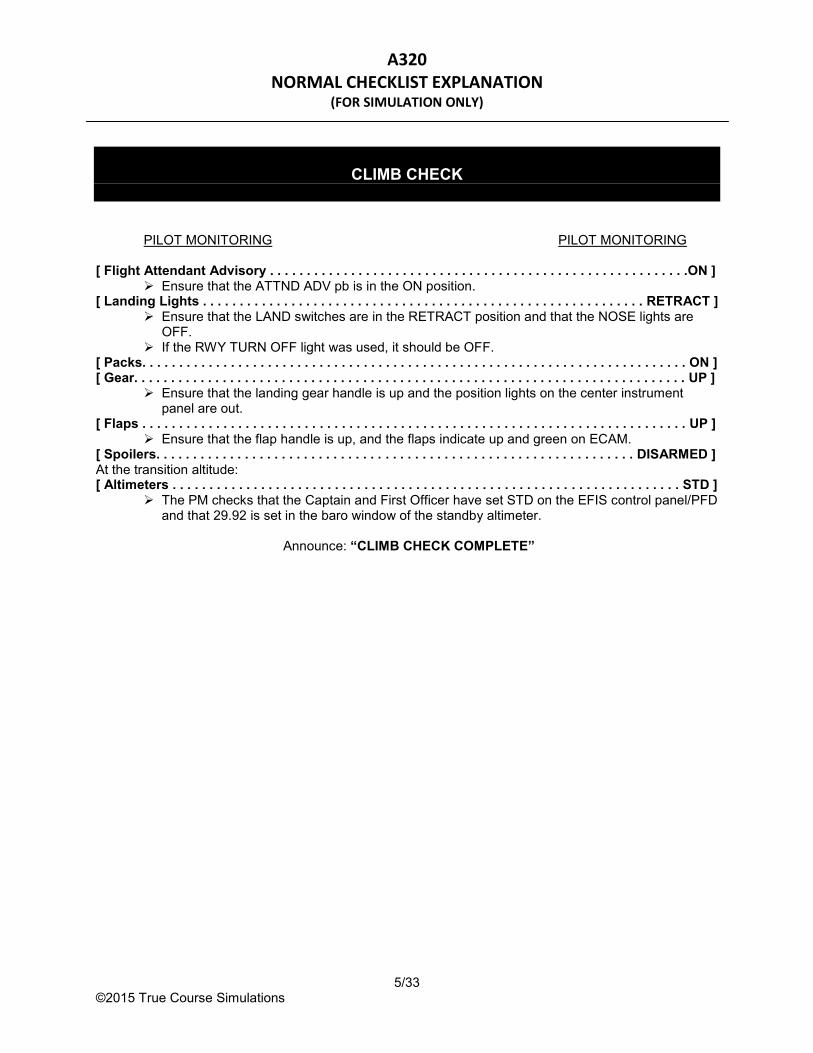
PILOT MONITORING PILOT MONITORING [ Flight Attendant Advisory . . . . . . . . . . . . . . . . . . . . . . . . . . . . . . . . . . . . . . . . . . . . . . . . . . . . . . . . .ON ]
Ensure that the ATTND ADV pb is in the ON position. [ Landing Lights . . . . . . . . . . . . . . . . . . . . . . . . . . . . . . . . . . . . . . . . . . . . . . . . . . . . . . . . . . . . RETRACT ]
Ensure that the LAND switches are in the RETRACT position and that the NOSE lights are OFF.
If the RWY TURN OFF light was used, it should be OFF. [ Packs. . . . . . . . . . . . . . . . . . . . . . . . . . . . . . . . . . . . . . . . . . . . . . . . . . . . . . . . . . . . . . . . . . . . . . . . . . ON ] [ Gear. . . . . . . . . . . . . . . . . . . . . . . . . . . . . . . . . . . . . . . . . . . . . . . . . . . . . . . . . . . . . . . . . . . . . . . . . . . UP ]
Ensure that the landing gear handle is up and the position lights on the center instrument panel are out.
[ Flaps . . . . . . . . . . . . . . . . . . . . . . . . . . . . . . . . . . . . . . . . . . . . . . . . . . . . . . . . . . . . . . . . . . . . . . . . . . UP ] Ensure that the flap handle is up, and the flaps indicate up and green on ECAM.
[ Spoilers. . . . . . . . . . . . . . . . . . . . . . . . . . . . . . . . . . . . . . . . . . . . . . . . . . . . . . . . . . . . . . . . . DISARMED ] At the transition altitude: [ Altimeters . . . . . . . . . . . . . . . . . . . . . . . . . . . . . . . . . . . . . . . . . . . . . . . . . . . . . . . . . . . . . . . . . . . . . STD ]
The PM checks that the Captain and First Officer have set STD on the EFIS control panel/PFD and that 29.92 is set in the baro window of the standby altimeter.
Announce: “CLIMB CHECK COMPLETE”

A320 NORMAL CHECKLIST EXPLANATION
(FOR SIMULATION ONLY)
5/33 ©2015 True Course Simulations
DESCENT CHECK
PILOT MONITORING PILOT MONITORING [ Seat Belts Sign. . . . . . . . . . . . . . . . . . . . . . . . . . . . . . . . . . . . . . . . . . . . . . . . . . . . . . . . . . . . . . . . . .ON ] [ Altimeters . . . . . . . . . . . . . . . . . . . . . . . . . . . . . . . . . . . . . . . . . . . . . . . . . . . . . . . . . . . . .___ IN ___ FT ]
The PM will silently verify that all three altimeters are set correctly with respect to the transition altitude (local if below transition altitude, standard if above the transition altitude).
The PM also confirms that all three altitude indications are within tolerances. If the PM cannot verify that the altimeters have been correctly set, challenge “ALTIMETERS.” The Captain and First Officer will then respond as per SOPA.
ECAM Status. . . . . . . . . . . . . . . . . . . . . . . . . . . . . . . . . . . . . . . . . . . . . . . . . . . . . . . . . . . . . . . . CHECKED Allowable Landing Weight. . . . . . . . . . . . . . . . . . . . . . . . . . . . . . . . . . . . . . . . . . . . . . . . . . . . .CHECKED
CHECKED indicates that: the PM has determined that the estimated landing weight does not exceed the maximum
allowable landing weight or the climb limit weight for the existing conditions.
Announce: “DESCENT CHECK COMPLETE”

A320 NORMAL CHECKLIST EXPLANATION
(FOR SIMULATION ONLY)
5/33 ©2015 True Course Simulations
APPROACH CHECK
PILOT MONITORING PILOT MONITORING Flight Attendant Advisory . . . . . . . . . . . . . . . . . . . . . . . . . . . . . . . . . . . . . . . . . . . . . . . . . . . . . . . . . . OFF
The Flight Attendant Advisory light will alert the flight attendants of the approximate flight time remaining.
Also, ensure that the PA Announce:ment “FLIGHT ATTENDANTS PREPARE FOR LANDING” is made.
The response, “Off,” alerts the PF and observer(s) (if applicable) that the flight deck is now sterile.
Approach Briefing . . . . . . . . . . . . . . . . . . . . . . . . . . . . . . . . . . . . . . . . . . . . . . . . . . . . . . .(PF)COMPLETE The planned approach has been briefed.
Approach Freqs & Course. . . . . . . . . . . . . . . . . . . . . . . . . . . . . . . . . . . . . . . . . . . . . . . (BOTH) ___, ___° Respond with the frequency and course that are displayed on your respective PFD/ND for the
approach being flown. For an RNAV approach, respond with “RNAV.”
VAPP . . . . . . . . . . . . . . . . . . . . . . . . . . . . . . . . . . . . . . .(BOTH) ___ APPR NUMBERS CHECKED & SET Verify that the Approach Data Card for the estimated landing weight is displayed. Compare the card’s VLS against the VLS on the PERF APPR page for reasonableness. The response will include the actual value of the VAPP speed.
Minimums Bugs . . . . . . . . . . . . . . . . . . . . . . . . . . . . . . . . . . . . . . . . . . . . . . . . . . . . . (BOTH) SET ___ FT Check that the PFD displays the desired DA(H), MDA, or “NO DH”. The response will include the desired DA(H), MDA, or “NO DH.” For a visual approach, enter the minimums in the PERF APPR page for the ILS approach
being used as backup. If there is no ILS approach to the landing runway, enter the field elevation or TDZE (whichever
is higher) into the MDA field on the PERF APPR page. Select and adjust the Marker Beacon Audio, as desired.
Auto Brakes. . . . . . . . . . . . . . . . . . . . . . . . . . . . . . . . . . . . . . . . . . . . . . . . . . . . . . . . . . . . . . . . . LO (MED) The response will be “LOW” or “MEDIUM” as set on the center instrument panel.
Announce: “APPROACH CHECK COMPLETE”

A320 NORMAL CHECKLIST EXPLANATION
(FOR SIMULATION ONLY)
5/33 ©2015 True Course Simulations
LANDING CHECK
PILOT MONITORING PILOT MONITORING [ Flight Attendants . . . . . . . . . . . . . . . . . . . . . . . . . . . . . . . . . . . . . . . . . . . . . . . . . . . . . . . . . .NOTIFIED ]
NOTIFIED indicates that the PM has pressed the FWD and the AFT CALLS pbs to notify the flight attendants that the cabin should be prepared for landing.
Gear . . . . . . . . . . . . . . . . . . . . . . . . . . . . . . . . . . . . . . . . . . . . . . . . . . . . . . . . . . . . . . . . . DOWN & GREEN Flaps . . . . . . . . . . . . . . . . . . . . . . . . . . . . . . . . . . . . . . . . . . . . . . . . . . . . . . . . . . . . . . . . .___, ___, GREEN
The PM verifies that the proper flaps are set and responds with: The flap handle position, The indicated flap position, and “GREEN.”
Spoilers . . . . . . . . . . . . . . . . . . . . . . . . . . . . . . . . . . . . . . . . . . . . . . . . . . . . . . . . . . . . . . . . . . . . . . ARMED
Announce: “LANDING CHECK COMPLETE”
AFTER LANDING CHECK
FIRST OFFICER FIRST OFFICER [ Landing Lights . . . . . . . . . . . . . . . . . . . . . . . . . . . . . . . . . . . . . . . . . . . . . . . . . . . . . . . . . . . RETRACT ] [ Transponder . . . . . . . . . . . . . . . . . . . . . . . . . . . . . . . . . . . . . . . . . . . . . . . . . . . . . . . . . . . . ON (STBY) ]
Place the TCAS/Transponder Mode Selector to ON for the taxi to the gate, if required by ATC. [ Flaps . . . . . . . . . . . . . . . . . . . . . . . . . . . . . . . . . . . . . . . . . . . . . . . . . . . . . . . . . . . . . . . . . . . . . . . . . . UP ] [ Spoilers. . . . . . . . . . . . . . . . . . . . . . . . . . . . . . . . . . . . . . . . . . . . . . . . . . . . . . . . . . . . . . . . . DISARMED ] [ Radar. . . . . . . . . . . . . . . . . . . . . . . . . . . . . . . . . . . . . . . . . . . . . . . . . . . . . . . . . . . . . . . . . . . . . . . . . OFF ]
Announce: “AFTER LANDING CHECK COMPLETE”

A320 NORMAL CHECKLIST EXPLANATION
(FOR SIMULATION ONLY)
5/33 ©2015 True Course Simulations
PARKING CHECK
FIRST OFFICER CAPTAIN Flight Attendant Advisory . . . . . . . . . . . . . . . . . . . . . . . . . . . . . . . . . . . . . . . . . . . . . . . . . . . . . . . . . . . ON
Ensure that the ATTND ADV pb is in the ON position. Beacon. . . . . . . . . . . . . . . . . . . . . . . . . . . . . . . . . . . . . . . . . . . . . . . . . . . . . . . . . . . . . . . . . . . . . . . . . . OFF Seat Belts Sign . . . . . . . . . . . . . . . . . . . . . . . . . . . . . . . . . . . . . . . . . . . . . . . . . . . . . . . . . . . . . . . . . . . OFF Ice Protection . . . . . . . . . . . . . . . . . . . . . . . . . . . . . . . . . . . . . . . . . . . . . . . . . . . . . . . . . . . . . . . . . . . . OFF Fuel Pumps. . . . . . . . . . . . . . . . . . . . . . . . . . . . . . . . . . . . . . . . . . . . . . . . . . . . . . . . . . . . . . . . . . . . . . OFF
Ensure that all of the fuel pump pbs are OFF. Leave the MODE SEL in the AUTO mode.
Yellow Electric Pump . . . . . . . . . . . . . . . . . . . . . . . . . . . . . . . . . . . . . . . . . . . . . . . . . . . . . . . . . . . . . .OFF Engine Master Switches. . . . . . . . . . . . . . . . . . . . . . . . . . . . . . . . . . . . . . . . . . . . (C) OFF/(FO) VERIFIED
Captain verifies both Engine Master Switches are in the OFF position. First Officer verifies both engines have shut down by monitoring the engine instruments.
Transponder . . . . . . . . . . . . . . . . . . . . . . . . . . . . . . . . . . . . . . . . . . . . . . . . . . . . . . . . . . . . . . . . . . . .STBY Chocks Signal. . . . . . . . . . . . . . . . . . . . . . . . . . . . . . . . . . . . . . . . . . . . . . . RECEIVED (NOT RECEIVED) Brakes . . . . . . . . . . . . . . . . . . . . . . . . . . . . . . . . . . . . . . . . . . . . . . . . . . . . . . . . . . . . . . . . . . . . .OFF (SET)
If the chocks signal is not received, the brakes must remain set until the crew has verified that chocks have been inserted.
After the chocks are inserted, the brakes should be released for cooling. If the ramp is contaminated with ice or snow, or high winds exist or are anticipated, the parking
brakes should remain set.
Announce: “PARKING CHECK COMPLETE”

A320 NORMAL CHECKLIST EXPLANATION
(FOR SIMULATION ONLY)
5/33 ©2015 True Course Simulations
SECURING CHECK
ADIRS. . . . . . . . . . . . . . . . . . . . . . . . . . . . . . . . . . . . . . . . . . . . . . . . . . . . . . . . . . . . . . . . . . . . . . . . . . . OFF Oxygen. . . . . . . . . . . . . . . . . . . . . . . . . . . . . . . . . . . . . . . . . . . . . . . . . . . . . . . . . . . . . . . . . . . . . . . . . . OFF
Check that the OXYGEN CREW SUPPLY pb is OFF. No Smoking Sign . . . . . . . . . . . . . . . . . . . . . . . . . . . . . . . . . . . . . . . . . . . . . . . . . . . . . . . . . . . . . . . . . OFF APU Bleed. . . . . . . . . . . . . . . . . . . . . . . . . . . . . . . . . . . . . . . . . . . . . . . . . . . . . . . . . . . . . . . . . . . . . . . OFF Integral Lights. . . . . . . . . . . . . . . . . . . . . . . . . . . . . . . . . . . . . . . . . . . . . . . . . . . . . . . . . . . . . . . . . . . . OFF
Check that all integral lights are OFF. Ensure that all the display units are OFF.
After the last passenger has deplaned: Emergency Lights. . . . . . . . . . . . . . . . . . . . . . . . . . . . . . . . . . . . . . . . . . . . . . . . . . . . . . . . . . . . . . . . . OFF APU Master . . . . . . . . . . . . . . . . . . . . . . . . . . . . . . . . . . . . . . . . . . . . . . . . . . . . . . . . . . . . . . . . . .OFF (ON) Note: Allow the APU automatic cool down cycle to complete and the flap to close prior to removing battery power. This process takes approximately two minutes. Batteries 1 & 2. . . . . . . . . . . . . . . . . . . . . . . . . . . . . . . . . . . . . . . . . . . . . . . . . . . . . . . . . . . . . . . .OFF (ON)
The following are options (in order of preference) to complete the securing check: 1. If the aircraft is being completely powered down with EXT PWR plugged in, use the following
sequence: MAINT BUS switch: toggle ON (located behind the overhead plexiglas panel in forward
galley). External Power: OFF (AVAIL light illuminated) Battery pbs: OFF
Note: Powering down to the MAINT BUS extends the life of flight deck avionics equipment while allowing ground personnel to work in a lighted environment.
2. If the aircraft is being completely powered down with no EXT PWR, place the battery pbs to OFF.
3. If the aircraft is left on external power, place the battery pbs to OFF. 4. If the APU is running, leave the battery pbs ON so that APU fire protection is available.
Announce: “SECURING CHECK COMPLETE”
A320 STANDARD OPERATING PROCEDURES - AMPLIFIED
(FOR SIMULATION ONLY)
16/33 ©2015 True Course Simulations
PREFLIGHT
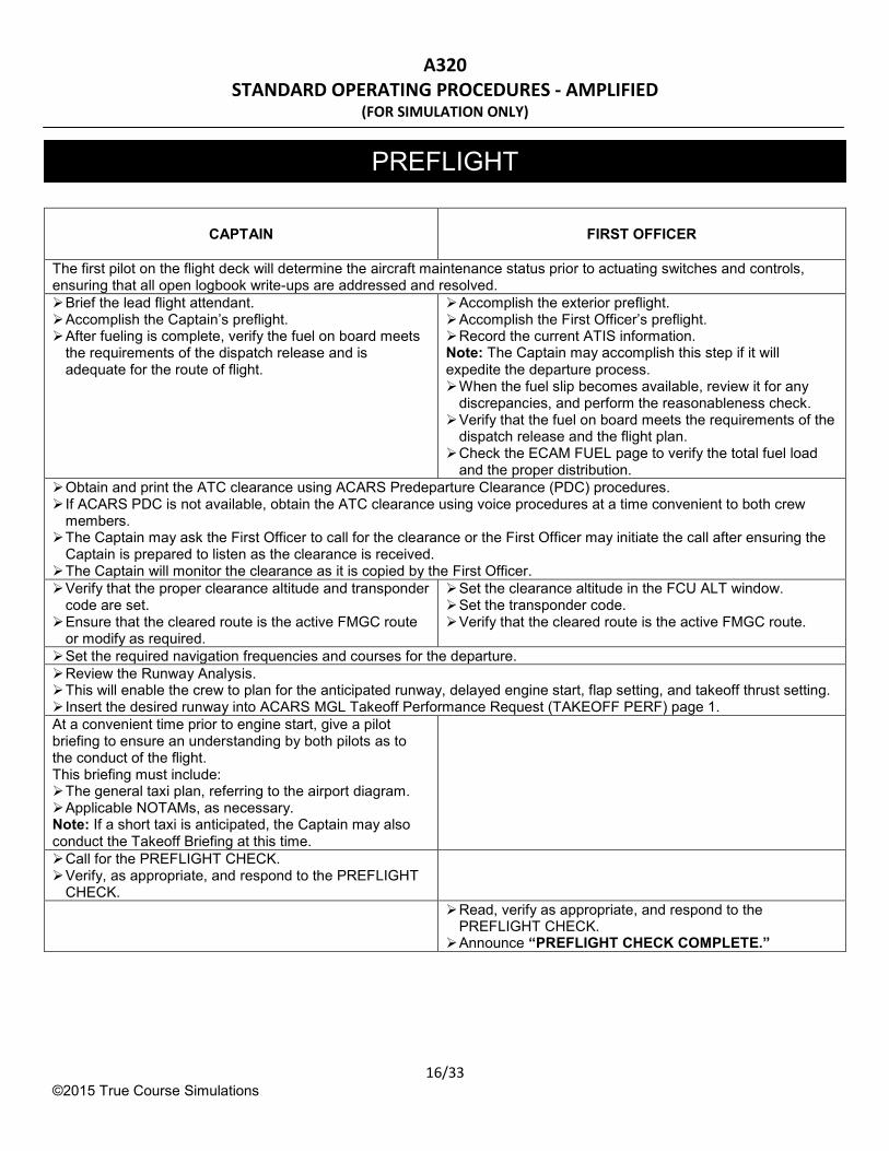
CAPTAIN FIRST OFFICER
The first pilot on the flight deck will determine the aircraft maintenance status prior to actuating switches and controls, ensuring that all open logbook write-ups are addressed and resolved.
Brief the lead flight attendant. Accomplish the Captain’s preflight. After fueling is complete, verify the fuel on board meets
the requirements of the dispatch release and is adequate for the route of flight.
Accomplish the exterior preflight. Accomplish the First Officer’s preflight. Record the current ATIS information. Note: The Captain may accomplish this step if it will expedite the departure process. When the fuel slip becomes available, review it for any
discrepancies, and perform the reasonableness check. Verify that the fuel on board meets the requirements of the
dispatch release and the flight plan. Check the ECAM FUEL page to verify the total fuel load
and the proper distribution.
Obtain and print the ATC clearance using ACARS Predeparture Clearance (PDC) procedures. If ACARS PDC is not available, obtain the ATC clearance using voice procedures at a time convenient to both crew
members. The Captain may ask the First Officer to call for the clearance or the First Officer may initiate the call after ensuring the
Captain is prepared to listen as the clearance is received. The Captain will monitor the clearance as it is copied by the First Officer.
Verify that the proper clearance altitude and transponder code are set.
Ensure that the cleared route is the active FMGC route or modify as required.
Set the clearance altitude in the FCU ALT window. Set the transponder code. Verify that the cleared route is the active FMGC route.
Set the required navigation frequencies and courses for the departure.
Review the Runway Analysis. This will enable the crew to plan for the anticipated runway, delayed engine start, flap setting, and takeoff thrust setting. Insert the desired runway into ACARS MGL Takeoff Performance Request (TAKEOFF PERF) page 1.
At a convenient time prior to engine start, give a pilot briefing to ensure an understanding by both pilots as to the conduct of the flight. This briefing must include: The general taxi plan, referring to the airport diagram. Applicable NOTAMs, as necessary. Note: If a short taxi is anticipated, the Captain may also conduct the Takeoff Briefing at this time.
Call for the PREFLIGHT CHECK. Verify, as appropriate, and respond to the PREFLIGHT
CHECK.
Read, verify as appropriate, and respond to the PREFLIGHT CHECK.
Announce “PREFLIGHT CHECK COMPLETE.”

A320 STANDARD OPERATING PROCEDURES - AMPLIFIED
(FOR SIMULATION ONLY)
17/33 ©2015 True Course Simulations
CAPTAIN
FIRST OFFICER
When any flight deck jump seat is occupied, ensure that each occupant views the Extra Crew Briefing Card, has an understanding of the oxygen and interphone systems, and knows the location of all emergency exits. Ensure that each occupant has a thorough understanding of sterile flight deck procedures.
If the passenger doors are closed and the pushback coordinator has not contacted the flight deck, the Captain will initiate contact to ensure an on-time departure.
Note: Flight Deck preparations should be complete down to the BEFORE START CHECK by five minutes prior to the scheduled pushback.
Review updated weather information.
Coordinate the pushback with the ground crew.
When the pushback coordinator transmits, “BRAKES SET FOR CHOCK REMOVAL?”:
Check the parking brake set, check the brake pressure, and transmit:
“BRAKES SET, PRESSURE NORMAL.”
When the pushback coordinator transmits, “BRAKES RELEASED, READY FOR PUSH?”:
Transmit, “STANDBY.”
Check that the ADIRS are in NAV with the ALIGN lights out and the alignment countdown on the upper ECAM is complete.
Place the Flight Attendant Advisory Light pb OFF. Place the BEACON switch ON. Place the SEAT BELTS switch ON. Verify that the NW STRG DISC ECAM Memo is
displayed. CAUTION: If this memo is not displayed, do not pushback. Verify that the lower ECAM indicates that all doors are
green and slides are armed.
Check that the APU BLEED pb is ON. Check that external power has been disconnected
(unless using external power for the start). Place the Fuel Pump pbs ON. Verify the flight deck door is closed and secured
(OPEN/FAULT light on pedestal COCKPIT DOOR panel is lights out).
Call for the BEFORE START CHECK. Verify, as appropriate, and respond to the BEFORE
START CHECK.
Read, verify as appropriate, and respond to the BEFORE START CHECK.
Announce “BEFORE START CHECK COMPLETE.”
Verify that all passengers are seated before moving the aircraft.
With the concurrence of the Captain, call for pushback clearance from ATC or ramp control after the BEFORE START CHECK is complete.
However, do not call for clearance sooner than one minute before the aircraft is expected to move.
Once the BEFORE START CHECK is complete, all passengers have been seated, and the pushback clearance has been received:
Release the parking brake and transmit: “BRAKES RELEASED, CLEARED TO PUSH.”
When pushback is complete and the pushback coordinator transmits, “BRAKES SET?”:
BEFORE START

A320 STANDARD OPERATING PROCEDURES - AMPLIFIED
(FOR SIMULATION ONLY)
18/33 ©2015 True Course Simulations
Set the parking brake, check the brake pressure, and transmit: “BRAKES SET, PRESSURE NORMAL.”
CAPTAIN
FIRST OFFICER
When the pushback coordinator transmits “CLEARED TO START ENGINES”:
Transmit: “ROGER.”
The normal starting sequence is engine number one and then engine number two.
Call “IGN/START.” Rotate the ENG MODE selector to IGN/START and
announce “IGN/START.”
Announce: “STARTING ONE.”
Move the number one engine Master switch to ON. Announce: “OIL PRESSURE.” at the first indication. Monitor engine start for normal indications.
Announce: “ROTATION.” at the first indication of N2. Announce: “N ONE.” at the first indication of N1. Monitor engine start for normal indications.
Start the remaining engine, if desired, using the procedures described above.
When pushback is complete and the pushback coordinator transmits, “BRAKES SET.”
Set the parking brake, check the brake pressure, and transmit, “BRAKES SET, PRESSURE NORMAL.”
When the pushback coordinator is no longer required, transmit, “CLEARED TO DISCONNECT.”
The pushback coordinator will transmit, “STEERING BYPASS PIN REMOVED.” and “STANDBY FOR WAVEOFF ON THE LEFT/CENTER/RIGHT.” (as circumstances dictate).
When the aircraft is clear to taxi, the pushback coordinator will give the Clear to Taxi salute. This salute is normally given in view of the Captain, but may be given in view of the First Officer if circumstances dictate a waveoff on the right.
Return the Clear to Taxi salute or direct the First Officer to return the salute if the waveoff is on the right.
If directed by the Captain, return the Cleared to Taxi salute.
For low light conditions, the Clear to Taxi salute is acknowledged with a flash of the taxi light.
CAUTION: Do not initiate taxi until the signal person is clear of both the aircraft track and jet blast area.
ENGINE START
A320 STANDARD OPERATING PROCEDURES - AMPLIFIED
(FOR SIMULATION ONLY)
19/33 ©2015 True Course Simulations
CAPTAIN
FIRST OFFICER
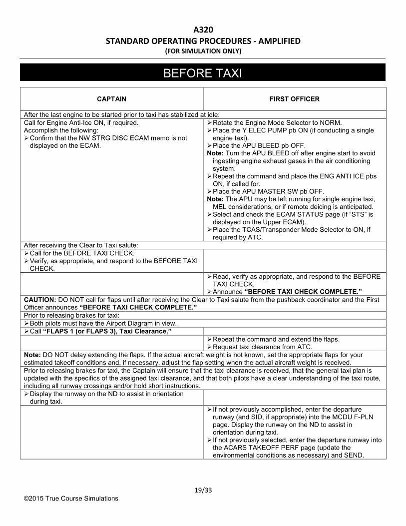
After the last engine to be started prior to taxi has stabilized at idle:
Call for Engine Anti-Ice ON, if required. Accomplish the following: Confirm that the NW STRG DISC ECAM memo is not
displayed on the ECAM.
Rotate the Engine Mode Selector to NORM. Place the Y ELEC PUMP pb ON (if conducting a single
engine taxi). Place the APU BLEED pb OFF. Note: Turn the APU BLEED off after engine start to avoid
ingesting engine exhaust gases in the air conditioning system.
Repeat the command and place the ENG ANTI ICE pbs ON, if called for.
Place the APU MASTER SW pb OFF. Note: The APU may be left running for single engine taxi,
MEL considerations, or if remote deicing is anticipated. Select and check the ECAM STATUS page (if “STS” is
displayed on the Upper ECAM). Place the TCAS/Transponder Mode Selector to ON, if
required by ATC.
After receiving the Clear to Taxi salute:
Call for the BEFORE TAXI CHECK. Verify, as appropriate, and respond to the BEFORE TAXI
CHECK.
Read, verify as appropriate, and respond to the BEFORE TAXI CHECK.
Announce “BEFORE TAXI CHECK COMPLETE.”
CAUTION: DO NOT call for flaps until after receiving the Clear to Taxi salute from the pushback coordinator and the First Officer announces “BEFORE TAXI CHECK COMPLETE.”
Prior to releasing brakes for taxi:
Both pilots must have the Airport Diagram in view.
Call “FLAPS 1 (or FLAPS 3), Taxi Clearance.”
Repeat the command and extend the flaps. Request taxi clearance from ATC.
Note: DO NOT delay extending the flaps. If the actual aircraft weight is not known, set the appropriate flaps for your estimated takeoff conditions and, if necessary, adjust the flap setting when the actual aircraft weight is received.
Prior to releasing brakes for taxi, the Captain will ensure that the taxi clearance is received, that the general taxi plan is updated with the specifics of the assigned taxi clearance, and that both pilots have a clear understanding of the taxi route, including all runway crossings and/or hold short instructions.
Display the runway on the ND to assist in orientation during taxi.
If not previously accomplished, enter the departure runway (and SID, if appropriate) into the MCDU F-PLN page. Display the runway on the ND to assist in orientation during taxi.
If not previously selected, enter the departure runway into the ACARS TAKEOFF PERF page (update the environmental conditions as necessary) and SEND.
BEFORE TAXI

A320 STANDARD OPERATING PROCEDURES - AMPLIFIED
(FOR SIMULATION ONLY)
20/33 ©2015 True Course Simulations
CAPTAIN
FIRST OFFICER
Depress and hold the brake pedals before selecting the PARK BRK handle OFF.
Check that the alternate (yellow) BRAKES pressure decreases to zero after releasing the PARK BRK.
Once the aircraft starts moving, check the efficiency of the normal (green) brake system.
After receiving the Final Load Data message (print the ACARS Weight Data page, if able): Note: Repeat the following steps if the Final Load Data message, the runway, or the runway conditions change.
Verify that the ACARS Weight Data Message and the Closeout MGL are valid (flight number, runway, flap setting, environmental conditions, etc.).
Verify that the TOGW does not exceed XTOG or RTOG and that the correct takeoff data and speeds are displayed.
Check rudder trim is set at approximately zero. Verify that the stabilizer trim is properly set by referencing
the trim wheel (%MAC), and cross-checked with the LOAD DATA.
Check the lower ECAM for proper gross weight. Check the upper ECAM for the proper thrust mode. Check the flight instruments for proper indications. Turn on and verify the operation of the weather radar
when thunderstorms or other potentially hazardous weather conditions may be encountered en route. Ensure that ground return is displayed on the ND and that no warning messages appear after a 45 second self test when the radar is turned on.
Verify that the ACARS Weight Data Message and the Final Load Data are valid (flight number, runway, flap setting, environmental conditions, etc.).
Verify that the TOGW does not exceed XTOG or RTOG and that the engine type is correct.
Access the FUEL PRED page and enter/verify: o ZFW/ZFWCG.
Verify the gross weight approximates TOGW on the Final Load Data message.
Access the PERF TAKE OFF page: If FLEX thrust is authorized, and with the concurrence of
the Captain, insert the FLEX temperature. Insert the appropriate takeoff V-speeds. Set the stabilizer trim referencing the ECAM F/CTL page.
Note the LOAD DATA %MAC and verify on the trim wheel.
Check the flight instruments for proper indications.
At least one F-PLN page must be displayed for takeoff. Confirm that both NDs are set to the lowest practical range and that the departure runway is displayed properly.
Call for the TAXI CHECK. Verify, as appropriate, and respond to the TAXI CHECK.
Read, verify as appropriate, and respond to the TAXI CHECK.
Announce “TAXI CHECK COMPLETE.”
In order to conserve fuel during an extensive delay, the Captain may elect to shut down engine number 2 while taxiing, or shut down both engines while parked. If both engines were started for initial taxi, allow a 3 minute warm-up period before shutting down one or both engines. CAUTION: Both engines must be stabilized at idle for at least three minutes prior to applying takeoff thrust (five minutes for the first flight of the day) to ensure operating temperatures are reached.
TAXI

A320 STANDARD OPERATING PROCEDURES - AMPLIFIED
(FOR SIMULATION ONLY)
21/33 ©2015 True Course Simulations
CAPTAIN
FIRST OFFICER
Accomplish the ALL ENGINES CHECK after the TAXI CHECK is complete and both engines are running.
Accomplish the ALL ENGINES CHECK prior to accomplishing the BEFORE TAKEOFF CHECK. When clear of congested areas and both engines started:
Check for full travel of the elevator, ailerons, and rudder and ensure control surfaces move in the proper direction.
Hold sidestick deflections for a sufficient time (minimum 1 second) to observe full travel on the ECAM F/CTL page.
Use the PEDALS DISC switch during the rudder check to prevent movement of the nosewheel.
Check for full travel of the elevator and ailerons (rudder travel is checked by Captain) and ensure control surfaces move in the proper direction.
Hold sidestick deflections for a sufficient time (minimum 1 second) to observe full travel on the ECAM F/CTL page.
While performing the flight controls check, the opposite pilot will maintain vigilance outside of the aircraft to ensure a safe taxi operation.
Call for the ALL ENGINES CHECK. Verify as appropriate, and respond to the ALL ENGINES
CHECK.
Read, verify as appropriate, and respond to the ALL ENGINES CHECK.
Announce “ALL ENGINES CHECK COMPLETE.”
ALL ENGINES CHECK

A320 STANDARD OPERATING PROCEDURES - AMPLIFIED
(FOR SIMULATION ONLY)
22/33 ©2015 True Course Simulations
CAPTAIN
FIRST OFFICER
CAUTION: DO NOT accomplish the BEFORE TAKEOFF CHECK until all engines are running and the aircraft is approaching the takeoff position.
CAUTION: DO NOT stow the checklist until the BEFORE TAKEOFF CHECK is complete.
The Captain will conduct a Takeoff Briefing prior to takeoff. This briefing, which may have been accomplished in conjunction with the Pilot Briefing, must include a review of critical
conditions affecting the GO/NO GO decision and RTO procedures. Brief EGPWS/Radar requirements as necessary.
Approximately two minutes prior to departure:
Delay departure if notified the cabin is not ready for departure.
Use the PA to make the following announcement: “FLIGHT ATTENDANTS PREPARE FOR DEPARTURE.”
Approaching the takeoff position:
Arm the spoilers. Check that the flaps are in the correct takeoff position. Check that the Takeoff Memo is all green. Ensure that the shoulder harness is on
Place the Pack 1 and Pack 2 pbs OFF, if required. Set the Auto Brakes to MAX (hold pb for 1 second). Depress the T.O. CONFIG pb and verify no warning and
that the upper ECAM display shows "TO CONFIG NORMAL".
Rotate the ENG Mode selector to IGN/START if the runway is contaminated with standing water, snow or ice; moderate rain is anticipated; or if moderate turbulence will be encountered during/after takeoff.
Verify that the proper transponder code is set and place the TCAS selector to RA/TA.
Ensure that the shoulder harness is on. Verify that the XCMs shoulder harnesses are on.
Call for the BEFORE TAKEOFF CHECK. Verify, as appropriate, and respond to the BEFORE
TAKEOFF CHECK.
Read, verify as appropriate, and respond to the BEFORE TAKEOFF CHECK.
Announce “BEFORE TAKEOFF CHECK COMPLETE.”
When cleared onto the runway:
Place the NOSE light switch to TAXI and the RWY TURN OFF light switch to ON.
Use airport signage, runway markings and flight instruments to verify that the aircraft is taxiing onto the proper takeoff runway.
When cleared for takeoff:
Place the LAND light switches ON and the NOSE light switch to T.O.
BEFORE TAKEOFF

A320 STANDARD OPERATING PROCEDURES - AMPLIFIED
(FOR SIMULATION ONLY)
23/33 ©2015 True Course Simulations
PILOT FLYING
PILOT MONITORING
CAUTION: DO NOT advance the thrust levers for takeoff until the BEFORE TAKEOFF CHECK is completed.
If the First Officer is the pilot flying, the Captain states, “YOU HAVE THE AIRCRAFT.” when transferring control. The First Officer acknowledges, “I HAVE THE AIRCRAFT.”
Repeat the initial clearance heading and altitude. Include the transition altitude, if other than 18,000 feet MSL. (Example: “RUNWAY HEADING TO FIVE THOUSAND FEET, TRANSITION ALTITUDE SEVEN THOUSAND.”).
After the aircraft is aligned with the runway, advance the thrust levers to approximately 50% N1.
Ensure that both engines are accelerating symmetrically prior to setting TOGA or FLEX.
Note: If crosswind is greater than 20 knots, set 50% N1, then rapidly set 70% N1, then set TOGA or FLEX.
Advance the thrust levers so that TOGA or FLEX is set by 40 KIAS and achieved by 60 KIAS.
Verify that the correct takeoff N1 is set prior to reaching
60 KIAS.
Scan the engine instruments to ensure proper performance.
Monitor ECAM messages and engine instruments to ensure proper performance.
At 80 KIAS, announce “EIGHTY KNOTS, THRUST NORMAL.”
Confirm that the airspeed is 80 KIAS and announce “CHECKS.”
At 100 KIAS, announce “ONE HUNDRED.” Announce each 20 knots to V1 (Example: “ONE TWENTY,” “ONE FORTY”). Note: DO NOT make the 20 knot call if it is within 10 knots
of the V1/VR speed. Announce “V ONE” at the V1 speed, if applicable. Note: This callout is only required when V1 is less than VR (Example: a contaminated runway or a FLAPS 3 takeoff). Just prior to reaching VR, announce “ROTATE.”
Confirm the speed and rotate to the takeoff pitch attitude commanded by the flight director.
When both the altimeter and vertical speed indicator show a positive climb, announce “POSITIVE RATE.”
Call “GEAR UP” after the altimeter and vertical speed indicator show a positive climb.
Repeat the command and retract the landing gear. Check the landing gear position indicators for proper
indications.
Monitor the flight instruments with emphasis on airspeed and attitude to ensure that all indications are consistent with a normal climb.
Monitor Distant or Close in community departure parameters as selected in the FMS.
Retard the thrust levers to the CL detent at thrust reduction altitude (the FMA flashes “LVR CLB”).
Place Pack 1 pb ON, if selected OFF for takeoff.
TAKEOFF

A320 STANDARD OPERATING PROCEDURES - AMPLIFIED
(FOR SIMULATION ONLY)
24/33 ©2015 True Course Simulations
Call for flap retraction, calling for each step separately in the proper sequence and at the proper speed.
The terminology will be: “FLAPS 2,” “FLAPS 1,” and “FLAPS UP.”
Repeat the command and retract the flaps. Check the flap position indicators for proper indications.
After the flaps are selected UP:
Call for Wing Anti-Ice ON, if required. Rotate the Engine Mode selector to NORM (if used for takeoff) unless continuous ignition is required due to atmospheric conditions.
Disarm the spoilers. Repeat the command and place the WING ANTI ICE
pb ON, if called for. Place Pack 2 pb ON, if selected OFF for takeoff.

A320 STANDARD OPERATING PROCEDURES - AMPLIFIED
(FOR SIMULATION ONLY)
25/33 ©2015 True Course Simulations
PILOT FLYING
PILOT MONITORING
Passing the transition altitude (if 10,000 feet MSL or below):
Set STD on the EFIS control panel. (C) Set 29.92 on the standby altimeter.
Set STD on the EFIS control panel.
Announce “STANDARD” and the flight level passing. (Example: “STANDARD, FLIGHT LEVEL SIX TWO”)
Announce ”STANDARD” and the flight level passing. (Example: “STANDARD, FLIGHT LEVEL SIX TWO.”)
Ensure that both pilots have set STD 29.92
Passing 10,000 feet MSL or FL100:
(C) Place the Landing Lights switch to RETRACT. (C) Place the Nose Light and RWY TURN OFF switches
to OFF.
Place the Flight Attendant Advisory pb ON (NON-STERILE).
Place the radar ON (if not already in use). Ensure that 121.5 is tuned and monitored on VHF-2.
Call for the CLIMB CHECK.
Read and verify the items of the CLIMB CHECK. If below the transition altitude, announce:
“CLIMB CHECK COMPLETE TO TRANSITION ALTITUDE.”
If above the transition altitude, announce: “CLIMB CHECK COMPLETE.”
(C) Place the Seat Belts switch OFF, if conditions permit. If the seat belt sign is left illuminated, continue to
evaluate conditions and place the switch OFF when able.
Clear any frequencies or courses on the RAD NAV page that are no longer needed.
Passing the transition altitude (if above 10,000 feet MSL):
Set STD on the EFIS control panel. (C) Set 29.92 on the standby altimeter.
Set STD on the EFIS control panel.
Announce: “STANDARD” and the flight level passing. (Example: “STANDARD, FLIGHT LEVEL ONE EIGHT
FIVE.”)
Announce: “STANDARD” and the flight level passing (Example: “STANDARD, FLIGHT LEVEL ONE EIGHT
FIVE.”)
Ensure that both pilots have set STD 29.92.
Announce: “CLIMB CHECK COMPLETE.”
CLIMB
A320 STANDARD OPERATING PROCEDURES - AMPLIFIED
(FOR SIMULATION ONLY)
26/33 ©2015 True Course Simulations
PILOT FLYING
PILOT MONITORING
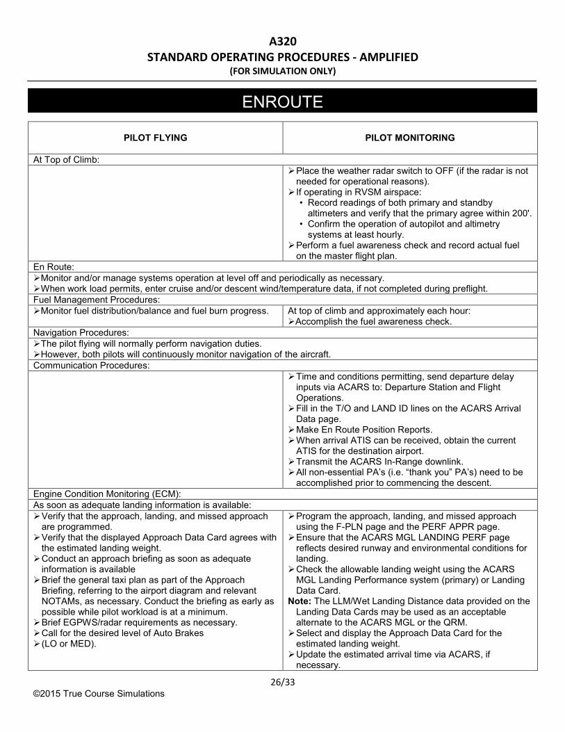
At Top of Climb:
Place the weather radar switch to OFF (if the radar is not needed for operational reasons).
If operating in RVSM airspace: • Record readings of both primary and standby
altimeters and verify that the primary agree within 200'. • Confirm the operation of autopilot and altimetry
systems at least hourly. Perform a fuel awareness check and record actual fuel
on the master flight plan.
En Route:
Monitor and/or manage systems operation at level off and periodically as necessary. When work load permits, enter cruise and/or descent wind/temperature data, if not completed during preflight.
Fuel Management Procedures:
Monitor fuel distribution/balance and fuel burn progress. At top of climb and approximately each hour: Accomplish the fuel awareness check.
Navigation Procedures:
The pilot flying will normally perform navigation duties. However, both pilots will continuously monitor navigation of the aircraft.
Communication Procedures:
Time and conditions permitting, send departure delay inputs via ACARS to: Departure Station and Flight Operations.
Fill in the T/O and LAND ID lines on the ACARS Arrival Data page.
Make En Route Position Reports. When arrival ATIS can be received, obtain the current
ATIS for the destination airport. Transmit the ACARS In-Range downlink. All non-essential PA’s (i.e. “thank you” PA’s) need to be
accomplished prior to commencing the descent.
Engine Condition Monitoring (ECM):
As soon as adequate landing information is available:
Verify that the approach, landing, and missed approach are programmed.
Verify that the displayed Approach Data Card agrees with the estimated landing weight.
Conduct an approach briefing as soon as adequate information is available
Brief the general taxi plan as part of the Approach Briefing, referring to the airport diagram and relevant NOTAMs, as necessary. Conduct the briefing as early as possible while pilot workload is at a minimum.
Brief EGPWS/radar requirements as necessary. Call for the desired level of Auto Brakes (LO or MED).
Program the approach, landing, and missed approach using the F-PLN page and the PERF APPR page.
Ensure that the ACARS MGL LANDING PERF page reflects desired runway and environmental conditions for landing.
Check the allowable landing weight using the ACARS MGL Landing Performance system (primary) or Landing Data Card.
Note: The LLM/Wet Landing Distance data provided on the Landing Data Cards may be used as an acceptable alternate to the ACARS MGL or the QRM.
Select and display the Approach Data Card for the estimated landing weight.
Update the estimated arrival time via ACARS, if necessary.
ENROUTE

A320 STANDARD OPERATING PROCEDURES - AMPLIFIED
(FOR SIMULATION ONLY)
27/33 ©2015 True Course Simulations
Arm the Auto Brakes as briefed (hold pb for 1 second).
PILOT FLYING
PILOT MONITORING
Accomplish the following prior to reaching FL180 or 18,000 feet MSL or leaving cruise altitude, if lower:
(C) Place the Seat Belts switch ON. Check the performance of the pressurization system. Ensure that the cabin altitude is consistent with the
altitude passing and that the cabin is descending at a comfortable rate.
If the transition level is other than FL180, the pilot flying will brief the transition level and whether the local altimeter will be in inches (IN), hectopascals (hPa), or millibars (Mb). CAUTION: If the altimeter setting given by ATIS or the ground station does not clearly state inches (IN), hectopascals (hPa), or millibars (Mb), question the station to eliminate any possible misunderstanding.
At the transition level (if FL180):
Verify the altitude and set the altimeter using the QNH in the units provided by the local controlling facility.
(C) Set the QNH on the standby altimeter.
Verify the altitude and set the altimeter using the QNH in the units provided by the local controlling facility.
Announce the QNH and the altitude passing (Example: “TWO NINE NINE SEVEN INCHES,
EIGHTEEN THOUSAND FEET”).
Announce the QNH and the altitude passing (Example: “TWO NINE NINE SEVEN INCHES,
EIGHTEEN THOUSAND FEET”).
Ensure that both pilots have set the proper altimeter setting.
At FL180 or 18,000 feet MSL, or leaving cruise altitude if lower:
Ensure that the shoulder harness is on. Accomplish the following: Check the ECAM status page if “STS” is displayed on the
upper ECAM. Ensure that the shoulder harness is on. Verify that the XCM’s shoulder harness is on.
Call for the DESCENT CHECK.
Read, verify as appropriate, and respond to the DESCENT CHECK.
Announce: “DESCENT CHECK COMPLETE.”
DESCENT

A320 STANDARD OPERATING PROCEDURES - AMPLIFIED
(FOR SIMULATION ONLY)
28/33 ©2015 True Course Simulations
PILOT FLYING
PILOT MONITORING
When the DESCENT CHECK is complete, but not lower than FL120 or 12,000 feet MSL:
Update the approach briefing as necessary. Verify that the appropriate minimums are displayed on
your PILOT FLYINGD.
Reprogram the approach as necessary. Verify that the appropriate minimums are displayed on
your PILOT FLYING ND. Place the Flight Attendant Advisory Light pb OFF. Use the PA system to make the following announcement:
“FLIGHT ATTENDANTS PREPARE FOR LANDING.”
Call for the APPROACH CHECK. Verify as appropriate and respond to the APPROACH
CHECK.
Read, verify as appropriate, and respond to the APPROACH CHECK.
Announce: “APPROACH CHECK COMPLETE.”
At the transition level (if below FL180):
Set the altimeter using the QNH in the units provided by the local controlling facility.
(C) Set the QNH on the standby altimeter.
Set the altimeter using the QNH in the units provided by the local controlling facility.
Announce the QNH and the altitude passing (Example: “TWO NINE NINE SEVEN INCHES, SIX THOUSAND FEET”).
Announce the QNH and the altitude passing (Example: “TWO NINE NINE SEVEN INCHES, SIX THOUSAND FEET”).
Ensure that all altimeters have been set to the proper altimeter setting.
If the landing runway or the approach changes after completing the APPROACH CHECK:
Update the approach briefing as necessary. Verify that the appropriate minimums are set. Call for the APPROACH CHECK. Verify as appropriate and respond to the APPROACH
CHECK.
Recheck the allowable landing weight. Reprogram the approach as necessary. Verify that the appropriate minimums are set. Read, verify as appropriate, and respond to the
APPROACH CHECK. Announce:
“APPROACH CHECK COMPLETE.”
Prior to descending below FL100 or 10,000 feet MSL:
(C) Place the Landing Light switches to ON.
When preparing for the approach: Activate the approach phase or request the PILOT
MONITORING to activate the approach phase.
Activate the approach phase, if requested by the PILOT FLYING.
When FLAPS 1 set, but no later than ten miles from touchdown:
Press the FWD CALLS button, then press the AFT CALLS button to advise the flight attendants of the short time remaining before touchdown.
If the ECAM STATUS page displays, review it prior to clearing.
Ensure that the Approach Phase has been activated.
APPROACH

A320 STANDARD OPERATING PROCEDURES - AMPLIFIED
(FOR SIMULATION ONLY)
29/33 ©2015 True Course Simulations
Rotate the Engine Mode selector to IGN/START (if the runway is wet or contaminated, moderate rain is anticipated, or if moderate turbulence will be encountered on approach or missed approach).
Call for flap extension in accordance with established procedures.
Repeat the command and extend the flaps. Check the flap/slat position indicator for proper
indications.
Call “GEAR DOWN” in accordance with established procedures for landing gear extension.
(Captain) Arm the spoilers.
Repeat the command and extend the landing gear. Check the landing gear position indicators for proper
indication.
After the landing gear is down and prior to 1,000 feet above TDZE:
Call for the landing flap setting and the LANDING CHECK (Example: “FLAPS _____ , LANDING CHECK”).
Verify as appropriate and respond to the LANDING CHECK.
Repeat the command and extend the flaps. Check the flap/slat position indicator for proper indications.
Read, verify as appropriate, and respond to the LANDING CHECK.
Note: When landing at an international airport (transition level other than FL180), the altimeters challenge and response must be verbalized.
Announce: “LANDING CHECK COMPLETE.”
Inside the Outer Marker (OM) or Final Approach Fix (FAF):
Ensure the missed approach altitude is set in the FCU altitude window when the setting is no longer needed for the approach.
Check that the Landing Memo is all green.

A320 STANDARD OPERATING PROCEDURES - AMPLIFIED
(FOR SIMULATION ONLY)
30/33 ©2015 True Course Simulations
PILOT FLYING
PILOT MONITORING
Select reverse idle thrust after main gear touchdown. Check that the spoilers show fully deployed on the ECAM WHEEL page.
Announce: “SPOILERS NORMAL”.
Make an appropriate awareness announcement if they fail to deploy automatically.
Apply reverse thrust as required after the reversers
normal call is made.
Announce: “REVERSERS NORMAL” when the REV indications change to green.
Make an appropriate awareness announcement if any
reverser fails to operate.
Apply reverse thrust as required down to 80 KIAS.
Monitor the auto brake system performance. Make an appropriate awareness announcement if the autobrakes fail to operate. At 80 KIAS, announce:
“EIGHTY KNOTS.”
By 80 KIAS begin reducing reverse thrust toward reverse idle and stow the thrust reversers (resume forward idle thrust) by 60 KIAS.
At 60 KIAS, announce: “SIXTY.”
If the First Officer is the pilot flying, the Captain states: “I HAVE THE AIRCRAFT” when taking control. The First Officer acknowledges: “YOU HAVE THE AIRCRAFT.”
Disengage the autopilot (if used) and the auto brakes prior to runway turnoff.
LANDING

A320 STANDARD OPERATING PROCEDURES - AMPLIFIED
(FOR SIMULATION ONLY)
31/33 ©2015 True Course Simulations
CAPTAIN
FIRST OFFICER
After clearing the runway (and it is assured that nearby active runways and taxiways can be safely crossed):
Call: “FLAPS UP, AFTER LANDING CHECK.”
Repeat:“FLAPS UP” and retract the flaps. Check the flap position indicators for proper position.
CAUTION: The First Officer should not allow the After Landing flows/checklist to divert attention from safely crossing active runways and taxiways.
CAUTION: DO NOT retract the flaps if a malfunction has occurred or contamination such as snow, ice, or slush is suspected.
After receiving the taxi clearance, the Captain will ensure that the general taxi plan is updated with the specifics of the assigned taxi clearance and that both pilots have a clear understanding of the taxi route, including all runway crossings and/or hold short instructions. Both pilots must have the Airport Diagram in view.
After the call “FLAPS UP, AFTER LANDING CHECK” is made:
Place the Landing Lights switch to RETRACT. Disarm the spoilers.
Request taxi clearance (if not already provided by ATC). Place the ENG ANTI ICE pbs OFF, unless conditions
require engine anti-ice for taxi. Place the WING ANTI ICE pb OFF. Place the approximate field elevation in the altitude
window of the FCU. Place the TCAS selector to STBY (ON if required by
ATC). Rotate the Engine Mode Selector to NORM (if used for
landing). Place (or check) the Radar switch OFF. Evaluate the need for the APU. If needed, start it on a
timely basis.
Read and verify the items of the AFTER LANDING CHECK.
Announce: “AFTER LANDING CHECK COMPLETE.”
If electrical power will be available at the gate, the APU should not be started. This decision must be tempered with consideration for air conditioning requirements.
Caution:The aircraft must be stopped with the parking brake set or taxied with no steering or braking inputs, while an electrical power source change occurs. Otherwise, unwanted steering and/or braking response may result.
Direct the First Officer to shut down engine #2 after three minutes of cooling at idle thrust (conditions permitting).
Announce: “SHUT DOWN ENGINE NUMBER TWO”.
Place Y ELEC PUMP pb ON. Place #2 ENG BLEED pb OFF. Move the number two engine Master switch to OFF. Scan the engine instruments (N1, EGT, N2, and FF) to
verify that the engine has been shut down. Announce: “ENGINE NUMBER TWO SHUT DOWN”.
Start the APU approximately one minute prior to gate arrival.
Approximately one aircraft length from the gate:
Place the Flight Attendant Advisory Light pb ON. Place the APU BLEED pb ON (if running and desired). Place #2 ENG BLEED pb OFF (if not done during single
AFTER LANDING
A320 STANDARD OPERATING PROCEDURES - AMPLIFIED
(FOR SIMULATION ONLY)
32/33 ©2015 True Course Simulations
engine taxi).
CAPTAIN
FIRST OFFICER
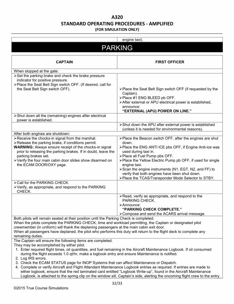
When stopped at the gate:
Set the parking brake and check the brake pressure indicator for positive pressure.
Place the Seat Belt Sign switch OFF. (If desired, call for the Seat Belt Sign switch OFF).
Place the Seat Belt Sign switch OFF (if requested by the
Captain). Place #1 ENG BLEED pb OFF. After external or APU electrical power is established,
announce: “EXTERNAL (APU) POWER ON LINE.”
Shut down all the (remaining) engines after electrical power is established.
Shut down the APU after external power is established (unless it is needed for environmental reasons).
After both engines are shutdown:
Receive the chocks-in signal from the marshal. Release the parking brake, if conditions permit. WARNING: Always ensure receipt of the chocks-in signal
prior to releasing the parking brakes. If in doubt, leave the parking brakes set.
Verify the four main cabin door slides show disarmed on the ECAM DOOR/OXY page.
Place the Beacon switch OFF, after the engines are shut down.
Place the ENG ANTI ICE pbs OFF, if Engine Anti-ice was used during taxi in.
Place all Fuel Pump pbs OFF. Place the Yellow Electric Pump pb OFF, if used for single
engine taxi. Scan the engine instruments (N1, EGT, N2, and FF) to
verify that both engines have been shut down. Place the TCAS/Transponder Mode Selector to STBY.
Call for the PARKING CHECK. Verify, as appropriate, and respond to the PARKING
CHECK.
Read, verify as appropriate, and respond to the PARKING CHECK.
Announce: “PARKING CHECK COMPLETE.”
Compose and send the ACARS arrival message.
Both pilots will remain seated at their position until the Parking Check is completed. When the pilots complete the PARKING CHECK, time and workload permitting, the Captain or designated pilot crewmember (in uniform) will thank the deplaning passengers at the main cabin exit door. When all passengers have deplaned, the pilot who performs this duty will return to the flight deck to complete any remaining duties.
The Captain will ensure the following items are completed. They may be accomplished by either pilot. 1. Enter required flight times, oil quantities, and fuel remaining in the Aircraft Maintenance Logbook. If oil consumed
during the flight exceeds 1.0 qt/hr, make a logbook entry and ensure Maintenance is notified. 2. Log IRS errors. 3. Check the ECAM STATUS page for INOP Systems that can affect Maintenance or Dispatch. 4. Complete or verify Aircraft and Flight Attendant Maintenance Logbook entries as required. If entries are made to
either logbook, ensure that the red laminated card entitled “Logbook Write-up”, found in the Aircraft Maintenance Logbook, is attached to the spring clip on the window sill, Captain’s side, alerting the oncoming flight crew to the entry.
PARKING

A320 STANDARD OPERATING PROCEDURES - AMPLIFIED
(FOR SIMULATION ONLY)
33/33 ©2015 True Course Simulations
5. Ensure that the APU is shut down before departing the aircraft unless it is needed for environmental reasons. If external power is not connected or available, all passengers must be off the aircraft before shutting down the APU.
CAPTAIN
FIRST OFFICER
When the flight is terminating and all systems are to be shut down.
Call for the SECURING CHECK. The Captain may accomplish and respond to the
SECURING CHECK or designate the First Officer to perform these duties.
Read and accomplish the SECURING CHECK. Announce:
“SECURING CHECK COMPLETE.”
SECURING


![A320 [AirlineEconomics]](https://img.pdfslide.us/doc/110x75/544c7f15b1af9fca498b4605/a320-airlineeconomics.jpg)