Embed Size (px)
Citation preview

1
Chapter 6: Real-Time Digital Time-Varying Harmonics Modeling and Simulation Techniques
Chapter 6: Real-Time Digital Time-Varying Harmonics Modeling and Simulation Techniques
Contributors: L-F. Pak, V. Dinavahi, G. Chang, M. Steurer, S. Suryanarayanan, P. Ribeiro
Organized by
Task Force on Harmonics Modeling & Simulation
Adapted and Presented by Paulo F Ribeiro
AMSC
May 28-29, 2008

2
Need for Sophisticated Tools for Power Quality (PQ) Studies
Proliferation of nonlinear and time-varying loads has led to significant power quality concerns. Traditionally, time-varying harmonics were studies using statistical and probabilistic methods for periodic harmonics.
Cannot describe random characteristics Cannot capture the reality of physical phenomena. A time-dependent spectrum is needed to compute the local power-frequency distribution at each instant.
Significant advances in equipment for PQ monitoring, waveform generation, disturbance detection, and mitigation.
Digital signal processing is widely used. Sophisticated power electronic controllers are used for PQ mitigation. Need for testing and validation of such equipment.
Real-time digital simulation as an advanced tool for PQ analysis and mitigation.

3
Real-Time Harmonic Modeling and Simulation Techniques
Wave Digital Filters
Discrete Wavelet Transform
Real-Time Electromagnetic Transient Network Solution
Real-Time Digital Simulators
RTDS PC-Cluster Based Simulators HYPERSIM DSPACE

4
(c)
(b)
(a)
AnalogElement
Realization by WDFs
PortResistance
Incident andReflected waves
A
B 0R
T
L
2
C
T
2
A
B
T
A
B -1
T
Wave Digital Filters
Digital Signal Processing tool that transforms analog networks into
topologically equivalent digital filters
Synthesis is based on wave network characterization
Designed to attain low-sensitivity structures to quantization errors in digital filter coefficients
Powerful technique for simulating power system harmonics and transients

5
Transient CapacitorModel
Steady-state CapacitorModel
Transient InductorModel
Steady-state InductorModel
dt
tdiLtv
)()(
WWTWW VLiLIDLV 0)0(
WVLiL 0)0( TWDL
+ -+-
0cv
SWSWWS IDLV
dt
tdvCti
)()(
TWINC
1
WTWWW IINC
VCvV 1
0)0(
WVCv 0)0(
+ --+
SDSW IINC
1
jkv )0(0ci
SWSWS IINC
WV 1
+ -+ -+ -
( b ) ( c )
Discrete Wavelet Transform
Time-Frequency representation of time varying
signals.
Wavelet analysis starts by adopting a prototype function. Time Analysis is done with a contracted high-frequency prototype. Frequency analysis is done using a dilated low-frequency prototype.
Operator representation theory is used to model electrical componenets in discrete wavelet domain

6
SIE
ME
NS
HiN
et W
S 4
40
0
1X
6X
13
X1
8
7X
12
X
19
X2
4
ST
AT
US
gre
en
= e
na
ble
d, lin
k OK
flash
ing
gre
en
=d
isab
led
,link O
Ko
ff = lin
k fail
TC
VR
Mo
du
le
Pa
cket
Sta
tus
Pa
cket
Sta
tus
13
14
15
16
18
19
20
21
22
23
24
13
14
15
16
18
19
20
21
22
23
24
12
34
56
78
91
01
11
21
23
45
67
89
10
11
12
17
17
25
X2
6X
24
24
26
26
10BaseT
X/100B
ase TX
Pa
cket
Sta
tus
UN
IT
12
34
56
78
COL-ACT-STA-
1 2 3 4 5 6 7 8 9101112HS1 HS2 OK1 OK2 PS
CONSOLE
Hosts
Gigabit
Target Cluster
Infini-BandLink
Closed-LoopController Testing
Hardware-in-the-LoopMachine Testing
Ethernet
PC-Cluster Based Real-Time Digital Simulator
Real-Time eXperimental LABoratory (RTX-LAB) at the University of Alberta.

7
Fully Flexible and scalable
Fast FPGA based analog and digital I/O and high intra-node communication speed
Varity of synchronization options
Compatible with MATLAB/SIMULINK and other programming languages
Features of the RTX-LAB Simulator

8
Target Cluster
Hosts
External Hardware
External Hardware
Host 1
FPGA 1(Signal Conditioning)
FPGA n(Signal Conditioning)
Shared
Memory
CPU1
CPU2
Cluster Node 2 (Dual XEON)
Shared
Memory
CPU1
CPU2
Cluster Node 1 (Dual XEON)
Shared
Memory
CPU1
CPU2
Cluster Node n (Dual XEON)
INFINIBAND
LINK
SIG
NAL
WIRE
GIGABIT
ETHERNET
Host 2
Host n
Two types of computers- Targets and Hosts
Targets are dual CPU based 3.0 GHZ Xeon, work as the main simulation engine and facilitates FPGA based I/Os
Hosts are 3.00 GHZ Pentium IV, used for model development, compilation and loading of the model to the cluster
Hardware Architecture of the RTX-LAB Simulator

9
Software Architecture of the RTX-LAB Simulator
Software Architecture of the RTX-LAB Simulator
Target Cluster
External Hardware
Hosts
SIMULINK
Intra-Node Communication
Real-Time OS
- Real-Time Linux- CPU Shielding
- Parallel Simulation- Multi-Rate Simulation
- Real-Time Communication
Signal-Wire
Real-Time Network Interface
Infiniband
CBB (Constant
Bi-Sectional Bandwidth)
Hardware Communication
- A/D and D/A Conversion- Signal Conditioning
- Fast DMA Burst Transfer Using FPGA
Model Development
System ModelControl Model
S-functionCustom Solver
Real-Time Communication
SchedulingData Acquisition
I/O Management
TCP/IP SIMULINKLabViewPythonOthers
GUI
Compilation
Real-Time Workshop (RTW)
Cluster NodeTarget OS- RedHawk Linux
Host OS- Windows XP
Model Development-
MATLAB/SIMULINK
Other programming Languages C, C++

10
InfiniBand Link
Maximum Throughput- 10Gbps
Shared Memory
bus speed – 2.67Gbps
Signal Wire Link
Data Transfer rate-1.2Gbps
Gigabit Ethernet link
Transfer Rate- Up to 1Gbps
I/O signals from real-hardware are connected through FPGA based I/Os
Xilinx Virtex-II Pro is used
100 MHZ operation speed
Communication Links in the RTX-LAB Simulator

11
(a)
(b)
I/O Comp. Wait for Sync
One time-step
I/O Comp. Wait for Sync
One time-step
One time-step One time-step
I/O Recv
Sen
d
One time-step
I/O Recv
Sen
d
One time-step
Master Subsystem
Slave Subsystem
I/O Comp.Wait for
SyncSen
d
Rec
v
I/O Comp.Wait for
SyncSen
d
Rec
v
AC
Q
AC
Q
AC
Q
AC
Q
AC
Q
AC
Q
Com
p.
Com
p.
Comp : ComputationACQ : AcquisitionRecv : ReceiveSync : Synchronization
External Hardware
Slave(Subsystem 1)
Controlsystem
Console(Subsystem 3)
User Interface
GatingPulses
Te*
m*
m
Master(Subsystem 2)
Electricalsystem
Iabc
Target Cluster Hosts
Cluster Node 1
Cluster Node 2
Host 1
Subsystems and Synchronization in the RTX-LAB Simulator

12
VL-L = 220 kV
Power grid
RT1 = 0.002 p.u.LT1 = 0.55 p.u.
220 kV / 45 kV
HV/MV Transformer
Y
RT2 = 0.002 p.u.LT2 = 0.55 p.u.
45 kV / 600 V
MV/LV Transformer
Y
RS = 0.001 p.u.LS = 0.005 p.u.
Case Study 1: Time-Varying Harmonic Analysis on the RTX-LAB Real-Time Digital Simulator
Single-line Diagram of the Arc Furnace Installation
13
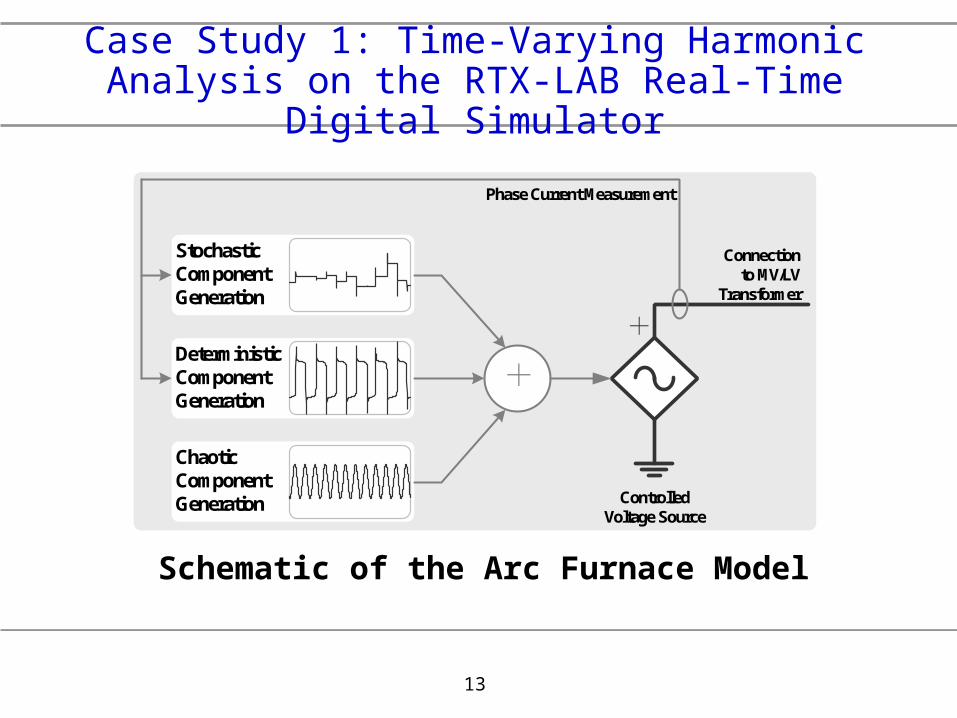
ChaoticComponentGeneration
DeterministicComponentGeneration
StochasticComponentGeneration
++
ControlledVoltage Source
Connectionto MV/LV
Transformer
Phase Current Measurement
Case Study 1: Time-Varying Harmonic Analysis on the RTX-LAB Real-Time Digital Simulator
Schematic of the Arc Furnace Model

14
1st
3rd
5th7th
9th
Case Study 1: Time-Varying Harmonic Analysis on the RTX-LAB Real-Time Digital Simulator
Voltage and Current for the Arc Furnace

15
1st
5th 7th
Case Study 1: Time-Varying Harmonic Analysis on the RTX-LAB Real-Time Digital Simulator
Voltage at the Primary Winding of the MV/LV Transformer

16
1st
5th
Case Study 1: Time-Varying Harmonic Analysis on the RTX-LAB Real-Time Digital Simulator
Current in the Primary Winding of the MV/LV Transformer

17
3PC-1
3PC-2
Rack 1
3PC-3
3PC-4
3PC-5
3PC-6
3PC-7
3PC-8
3PC-9
3PC-10
DOPTO-1
RPC
IRC
WIF
3PC-1
3PC-2
Rack 2
3PC-3
3PC-4
3PC-5
3PC-6
3PC-7
3PC-8
3PC-9
3PC-10
DOPTO-1
RPC
IRC
WIF
DOPTO-2
3PC-1
3PC-2
Rack 3
3PC-3
3PC-4
3PC-5
3PC-6
3PC-7
3PC-8
3PC-9
3PC-10
DOPTO-1
RPC
IRC
WIF
3PC-1
3PC-2
Rack 4
3PC-3
3PC-4
3PC-5
3PC-6
3PC-7
3PC-8
3PC-9
3PC-10
DOPTO-1
RPC
IRC
WIF
DOPTO-2
3PC-1
3PC-2
Rack 5
3PC-3
3PC-4
3PC-5
3PC-6
3PC-7
3PC-8
DOPTO-1
RPC
IRC
WIF
GPC
3PC-1
3PC-2
Rack 6
3PC-3
3PC-4
3PC-5
3PC-6
3PC-7
3PC-8
RPC
IRC
WIF
GPC
3PC-1
3PC-2
Rack 7
3PC-3
3PC-4
3PC-5
3PC-6
3PC-7
3PC-8
DOPTO-1
RPC
IRC
WIF
GPC
3PC-1
3PC-2
Rack 8
3PC-3
3PC-4
3PC-5
3PC-6
3PC-7
3PC-8
RPC
IRC
WIF
GPC
3PC-1
3PC-2
Rack 9
3PC-3
3PC-4
3PC-5
3PC-6
3PC-7
3PC-8
DOPTO-1
RPC
IRC
WIF
GPC
3PC-1
3PC-2
Rack 10
3PC-3
3PC-4
3PC-5
3PC-6
IRC
WIF
GPC-3
GPC-1
GPC-2
3PC-1
3PC-2
Rack 11
3PC-3
3PC-4
3PC-5
3PC-6
IRC
WIF
GPC-2
GPC-1
3PC-1
3PC-2
Rack 12
3PC-3
3PC-4
3PC-5
3PC-6
IRC
WIF
GPC-2
GPC-1
3PC-1
3PC-2
Rack 13
3PC-3
3PC-4
3PC-5
3PC-6
IRC
WIF
GPC-2
GPC-1
3PC-1
3PC-2
Rack 14
3PC-3
3PC-4
3PC-5
3PC-6
IRC
WIF
GPC-2
GPC-1
• Provides time domain solution in real time with typical time step sizes around 50 μs using the Dommel (EMTP) algorithm
• Features dual time step (<2 μs) capability for PE simulations
• Allows up to 54 electrical nodes per rack, but subsystems can be connected through cross-rack elements (transmission lines, etc.)
• Large library of power system and control component models (like EMTDC)
• > 350 parallel DSPs
• > 2500 analog outputs and over 200 digital inputs and outputsRPC – Network Solution
IRC – Inter-rack Communication
WIF – Workstation Interface
3PC – Controls, system dynamics
GPC – Network solution, fast-switching converters
RTDS at CAPS

18
• Largest RT simulator installation in any university worldwide
• Systems of up to 250 three-phase buses
• Sufficient high-speed I/O to enable realistic HIL and PHIL experiments
14 Rack RTDS Installation at CAPS

19
(Controller) hardware in loop (HIL) and power hardware in loop PHIL
(Controller) hardware in loop (HIL) and power hardware in loop PHIL
Real Time Digital Simulator
Universalcontroller
D/A
A/D Protection relay
M
AC/AC power converter (Motor Drive)
External Hardware
System Data in Simulation
Hardware response
MG
G
G
Controller
Relay
DC Load
Simulated rest of system

20
IndustryDC
Load
Real-Time Digital Simulation on RTDSTM
+
-
RL =0.48 LL =1.00 mH
RT = 0.05 p.u.LT = 0.005 p.u.
Rsource = 0.05 p.u.Lsource = 0.005 p.u.
VL-L = 12.47 kV 12.47 kV / 480 V
Power Grid Distribution Transformer6-pulse
Thyristor Rectifier
YY
Enerpro® FCOF 6100 Three-PhaseThyristor Firing Board
Tested Hardware
VoltageSensing
GatingPulses
Case Study 2: Power Quality Sensitivity Study of a Controller on the RTDS
Schematic of the Industrial Distribution System and Rectifier Load

21
0.05 0.1 0.15 0.2 0.25
-10
-5
0
5
10
P r i
m a
r y v
o l t
a g
e (
k V )
0.05 0.1 0.15 0.2 0.25 0
0.1
0.2
0.3
0.4
Time (s)
D C
v o
l t a g
e (
k V
)
Case Study 2: Power Quality Sensitivity Study of a Controller on the RTDS
Single-phase Voltage Sag (40% reduction, no phase shift) and its Impact on Rectifier DC Output

22
0.05 0.1 0.15 0.2 0.25
-10
-5
0
5
10
P r i
m a
r y v
o l t a
g e
( k V
)
0.05 0.1 0.15 0.2 0.25 0
0.1
0.2
0.3
0.4
Time (s)
D C
v o l t a
g e
( k V
)
Case Study 2: Power Quality Sensitivity Study of a Controller on the RTDS
Phase-Shifted Single-phase Voltage Sag (40% reduction) and its Impact on Rectifier DC Output

23
0 0.01 0.02 0.03 0.04 0.05-5
0
5
time (s)
Vo
lta
ge
(kV
)
0 500 1000 1500 20000
0.05
0.1
frequency (Hz)Vo
lta
ge
Ma
gn
itu
ed
(kV
)Voltage (kV)
Case Study 3: Harmonic Distortion on the RTDSShipboard Power System

24
G M
GM
Wind Speed
Local Load
Capacitor Bank
SubstationLine Impedance
System Simulated in Real Time Simulator
To change the stiffness of the grid For reactive
power compensation
User Interaction
Simulated Wind Turbine Model
VSD
VSD
Rotor torque
iGT
Case Study 4: A HIL Simulation for Studying the Transient Behavior of Wind DG

25
0 0.02 0.04 0.06 0.08 0.1 0.12 0.14 0.16 0.18 0.2-0.1
-0.05
0
0.05
0.1
time (s)
curr
ent
(kA
)Simulation generator current
0 2 4 6 8 10 12 14 16 18 200
0.05
0.1
Order of Harmonic
Mag
nitu
de
Normalized FFT of the Current
Case Study 4: A HIL Simulation for Studying the Transient Behavior of Wind DG

26
Conclusions
With rising number of time-varying and nonlinear loads sophisticated harmonics modeling and simulation tools are needed.
A combination of fast topological methods and powerful real-time simulators can overcome limitations of off-line simulation tools.
A general review of current off-line harmonic modeling and simulation tools is presented.
Currently available real-time simulation techniques are discussed.
Two real-time case studies: arc furnace modeling and power quality sensitivity of a controller, are presented.