Embed Size (px)
Citation preview
1
CDMA-Based MAC Protocol CDMA-Based MAC Protocol for Wireless Ad Hoc Networksfor Wireless Ad Hoc Networks
Alaa Muqattash and Marwan KrunzDepartment of Electrical and Computer Engineering
The Unniversity of ArizonaTucson, Arizona 85719
alaa,[email protected]
2
GoalGoal
Propose a CDMA-based power controlled
MAC protocol for mobile ad hoc networksImproving the network throughput of a
MANETMaintaining low energy consumption

3
OutlineOutline
IntroductionNear-far Problem In RA-CDMAThe Proposed CA-CDMA ProtocolSimulationConclusions

4
IntroductionIntroduction
Challenges in current MANETsWhat is CDMA?Why apply CDMA technology to MANET?Preparation for using CDMA-based solution
s

5
Challenges in Current Challenges in Current MANETsMANETsIncrease the overall network throughputMaintaining low energy consumption for
packet processing and communications
6
What is CDMA?What is CDMA?
A spread spectrum technologyEach user occupies the entire available
bandwidthThe transmitter’s signal is multiplied by a
Pseudo-Random noise(PN) code.The receiver despreads the received signal
using a locally generated PN codeThe PN code is distinct for each signal
7
Why CDMA?Why CDMA?
Advantages of CDMA– Achieve much higher channel bandwidth
efficiency for a given wireless spectrum allocation
– Overcome strong intentional interference– Has been widely adopted in popular cellular
systems(for example, 3G systems)

8
Concurrent transmission Concurrent transmission Problem in IEEE802.11Problem in IEEE802.11IEEE 802.11 uses SS technology at physical
levelSince all signals are spread using a common
PN code, concurrent transmissions are rejected in the a vicinity of a receiver

9
Concurrent transmission Concurrent transmission Problem in IEEE802.11Problem in IEEE802.11 Example — Figure 1 A → B and C → D cannot take place at the same
time
Figure 1

10
Introduce CDMA to MAC ProtocolIntroduce CDMA to MAC Protocol
To increase network throughput, we try to apply CDMA technology to MAC protocol
11
PreparationPreparationDesigning a code assignment protocol
• Assign distinct codes to different terminals• Meet the requirement that all neighbor nodes of
a node have different PN codes
• Deciding a spreading-code protocol• Decide codes used for transmission and for
monitoring the channel in packet reception• Can be receiver based, transmitter-based, or a
hybrid
12
Near-far Problem In RA-Near-far Problem In RA-CDMA (random access CDMA (random access CDMA)CDMA)Limitation of previously proposed CDMA-
based MAC protocols Imperfect Orthogonality of CDMA CodesImpact of the MAI Problem on network
throughput

13
Previously Proposed CDMA-Previously Proposed CDMA-based MAC Protocolsbased MAC ProtocolsBased on random channel access
– A terminal can transmit a packet immediately disregarding the state of the channel
– Called Random access CDMA (RA-CDMA)
Limitation: Near-far problem– Although RA-CDMA are free of primary
collisions, multi-access interference (MAI) can lead to secondary collisions at a receiver
14
Near-far problemNear-far problem
When all transmission powers are equal, if the receiver is much closer in distance to transmitter STA1 than STA2, the signal of STA1 will arrive at the receiver with a sufficiently larger power than that of the STA2, causing incorrect decoding of the transmission STA2(i.e., a secondary collision).

15
Near-far problem(A Example)Near-far problem(A Example)
Figure 2

16
Imperfect Orthogonality of Imperfect Orthogonality of CDMA CodesCDMA CodesReasons for near-far problem
– Cross correlations between CDMA codes are nonzero, which can induce multi-access interference
MANETs are time-asynchronous– Signals originate from multiple transmitters– It is generally not feasible to have a common ti
me reference for all the transmissions that arrive at a receiver

17
Imperfect Orthogonality of Imperfect Orthogonality of CDMA CodesCDMA CodesMANETs are time-asynchronous
– Transmissions propagate through different paths, so they have different time delays
In an asynchronous system, it is not possible to design spreading codes that are completely orthogonal for all time offsets

18
Impact of the MAI ProblemImpact of the MAI Problem
The near-far problem can severely affect packet reception, and consequently, network throughput.
A measure of network throughput– EFP : the expected forward progress per
transmission, defined as the product of the local throughput of a terminal and the distance between the transmitter and the receiver

19
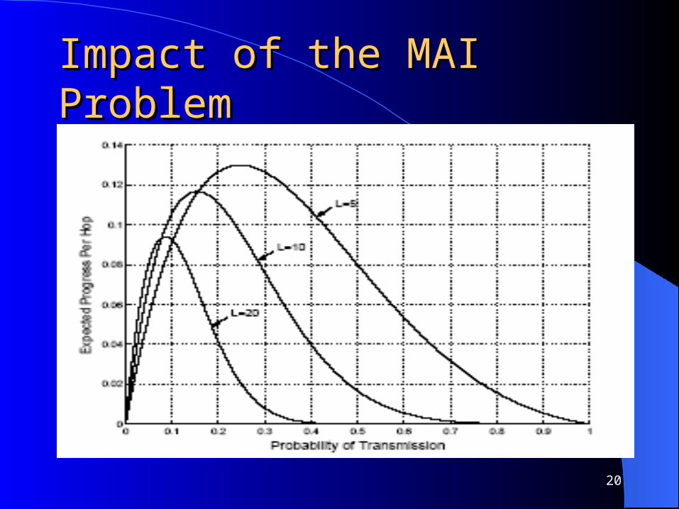
Impact of the MAI ProblemImpact of the MAI Problem
– P: the probability that a terminal is transmitting a packet in a given time slot
– L : the number of nodes that are within a circle centered at the transmitter and of radius that equals the transmitter-receiver separation distance.
Example: Figure 3: Throughput performance versus load in RA-CDMA networks
20
Impact of the MAI ProblemImpact of the MAI Problem

21
Impact of the MAI ProblemImpact of the MAI Problem
EFP starts to decrease rapidly when the load exceed P*
Our objective– Designing a CDMA-based MAC protocol that
prevents this rapid degradation in network throughput

22
The Proposed CA-CDMA The Proposed CA-CDMA ProtocolProtocolDesigning PrinciplesArchitectureChannel ModelControlled Access CDMA ProtocolInterference MarginChannel Access MechanismProtocol Recovery
23
Designing PrinciplesDesigning Principles
In CDMA Cellular Systems– Open- loop and closed-loop power control are e
mployed to have the signals of all STAs arrive at the base stations with the same power
The same solution cannot be used in MANETs.– In some cases multiple transmissions cannot tak
e place simultaneously– Example: Figure 4
24
Designing PrinciplesDesigning Principles
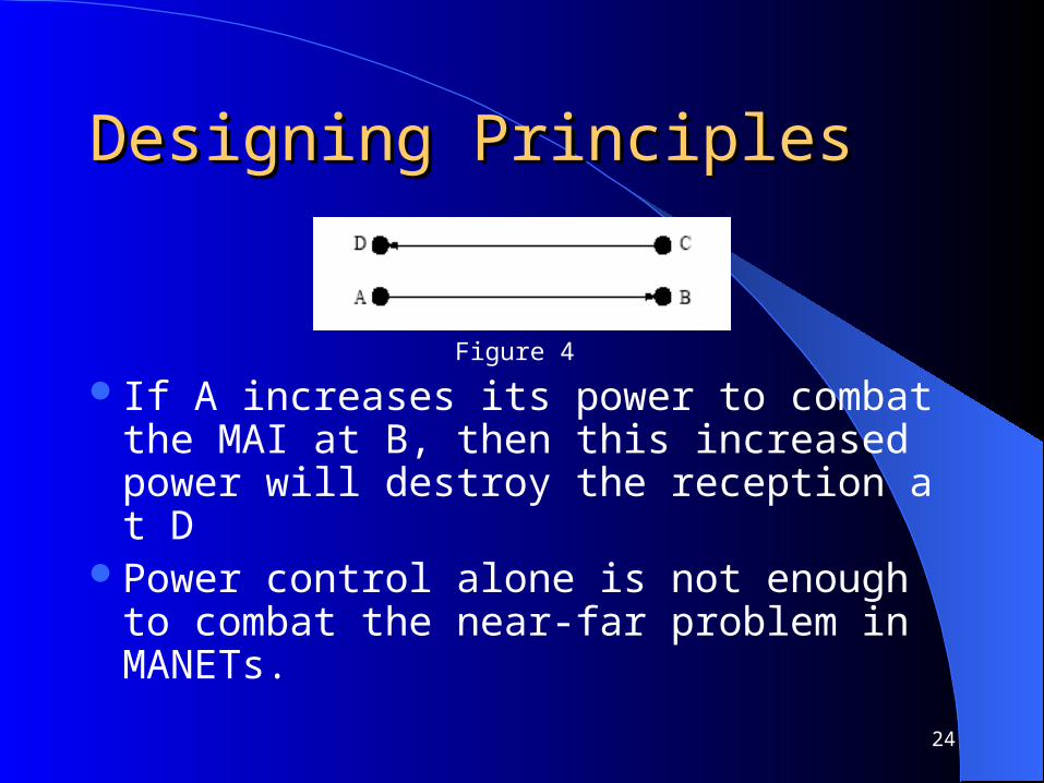
Figure 4
If A increases its power to combat the MAI at B, then this increased power will destroy the reception at D
Power control alone is not enough to combat the near-far problem in MANETs.
25
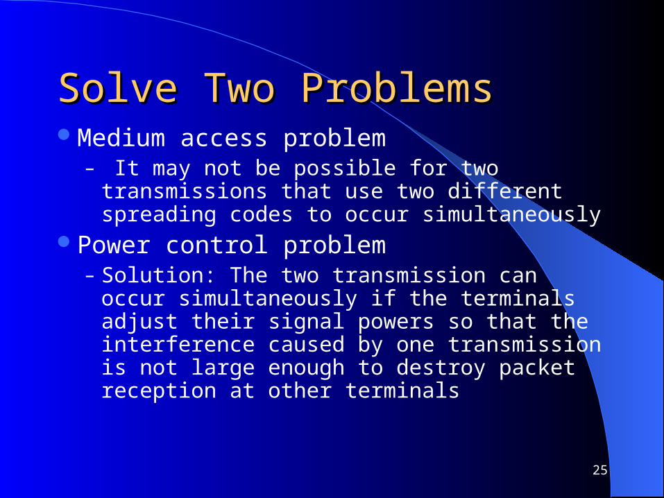
Solve Two ProblemsSolve Two ProblemsMedium access problem
– It may not be possible for two transmissions that use two different spreading codes to occur simultaneously
Power control problem– Solution: The two transmission can occur
simultaneously if the terminals adjust their signal powers so that the interference caused by one transmission is not large enough to destroy packet reception at other terminals

26
ArchitectureArchitectureTwo frequency channels
– One control channel– One data channel
Spreading code– A common spreading code is used by all nodes
over the control channel– Several terminal-specific codes can be used
over the data channel Signal over the control channel is
completely orthogonal to any signal over the data channel

27
ArchitectureArchitecture
Figure 5: Data and control codes in the proposed protocol

28
Protocol AssumptionsProtocol Assumptions The channel gain is stationary for the duration of
the control and the ensuing data packet transmission periods
The gain between two terminals is the same in both directions
Data and control packets between a pair of terminals observe similar channel gains.
Each terminal is equipped with two transceivers and a carrier-sense hardware that senses the control channel for any carrier signal

29
Protocol DescriptionProtocol Description RTS and CTS packets are transmitted over the
control channel (on the common code) at a fixed (maximum) power Pmax
Interfering nodes may be allowed to transmit concurrently
The receiver and the transmitter must agree on two parameters: the spreading code and the transmission power
Interference margin allows terminals at some interfering distance from the intended receiver to start new transmissions in the future

30
Protocol DescriptionProtocol Description
The power level is critical and represents a tradeoff between link quality and MAI
Apply a distributed admission control strategy that decides when terminals at some distance can transmit concurrently

31
Compute the Interference Compute the Interference MarginMarginMinimum required received power (P0
(i))min
– To achieve the target error rate, we have
P0(i) /(Pthermal + PMAI
(i) ) ≥ μ* , (1)
μ*—effective bit energy-to-noise spectral density ratio Eb/N0eff ,that is needed to achieve the target error rate
P0(i) — the average received power of the desired signal at the ith terminal;
Pthermal— the thermal noise power
PMAI (i) — the total MAI at receiver i
(P0(i))min = μ* (Pthermal + PMAI
(i) ) (2)

32
Noise Rise Noise Rise The interference margin depends on the network l
oad, which itself can be conveyed in terms of the noise rise (ξ(i))ξ(i) = (Eb/N0)unloaded / (Eb/N0)loaded) (3)
=(Pthermal + PMAI (i) )/ Pthermal
Thus (P0(i))min = ξ(i) μ* Pthermal (4)
The maximum planned noise rise is set asξ(max) ,

33
Interference MarginInterference Margin Assume that the transmission power attenuates wit
h the distance d as k/dn (k is a constant and n ≥ 2 is the loss factor).
The minimum required transmit power in CA-CDMA
PCA-CDMA = ξ(max) μ* Pthermal dn /k (5)
Assuming that d is uniformly distributed from 0 to dmax,we have the expectation of PCA-CDMA
E[PCA-CDMA ] = ξ(max) μ* Pthermal dnmax /k(n+1) (6)

34
Interference MarginInterference Margin As for the 802.11 protocol, its corresponding trans
mission
P802.11 = μ* Pthermal dnmax /k (7)
Therefore, to achieve equal average energy per bit consumption,we must have:
E[PCA-CDMA ] / RCA-CDMA = P802.11 /R802.11 ,(8)
RCA-CDMA and R802.11 are the bit rates for the transmitted data packets in the CA-CDMA and 802.11 protocols, respectively.
35
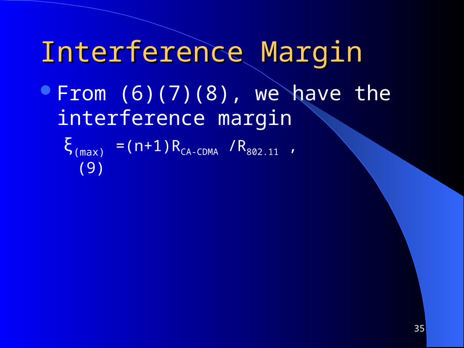
Interference MarginInterference MarginFrom (6)(7)(8), we have the interference
marginξ(max) =(n+1)RCA-CDMA /R802.11 , (9)

36
Channel Access MechanismChannel Access Mechanism The admission scheme allows only transmissions that will
not cause either primary or secondary collisions to proceed concurrently.– RTS/CTS packets allow nodes to estimate the channel gains
between transmitter-receiver pairs.– A receiver i uses the CTS packet to notify its neighbors of the
additional noise power(denoted by P(i)noise) that each of the
neighbors can add to terminal i without impacting i’s current reception
– Each terminal keeps listening to the control channel regardless of the signal destination in order to keep track of the average number of active users in their neighborhoods.

37
Channel Access MechanismChannel Access Mechanism Step 1
If terminal j has a packet to transmit, it sends a RTS
packet over the control channel at Pmax, and includes in
this packet the maximum allowable power level (P(j)map)
that terminal j can use that will not disturb any on going reception in j’s neighborhood.
The format of the RTS packet is similar to that of the IEEE 802.11, except for an additional two-byte field that contains the P(j)
map value.
38
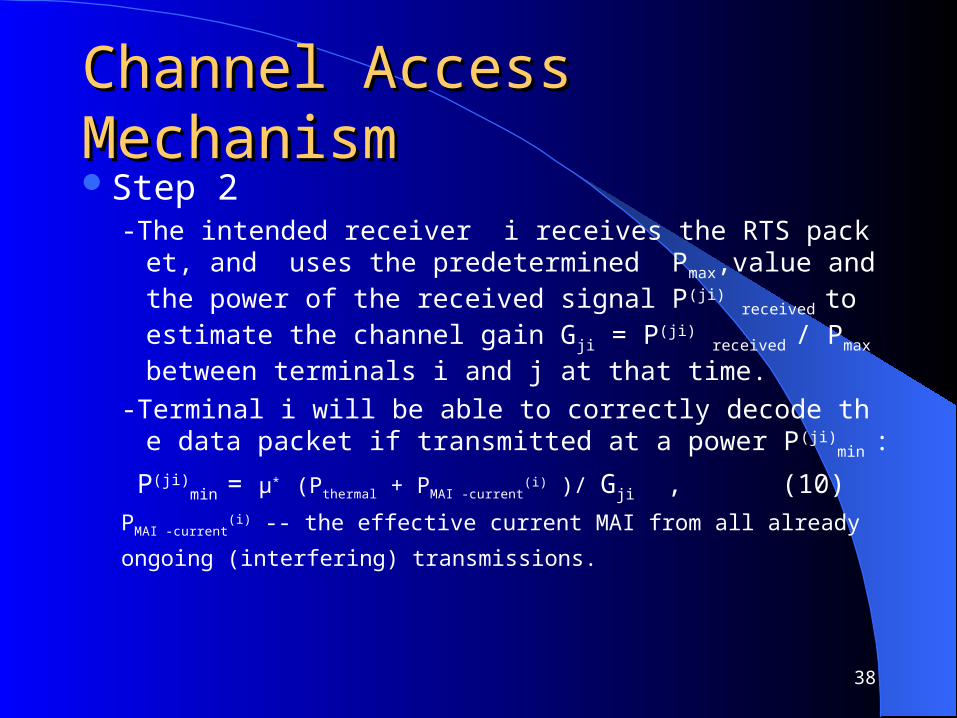
Channel Access MechanismChannel Access MechanismStep 2
-The intended receiver i receives the RTS packet, and uses the predetermined Pmax,value and the power of the received signal P(ji) received to estimate the channel gain Gji = P(ji) received / Pmax between terminals i and j at that time.
-Terminal i will be able to correctly decode the data packet if transmitted at a power P(ji)
min :
P(ji)min = μ* (Pthermal + PMAI -current
(i) )/ Gji , (10)
PMAI -current(i) -- the effective current MAI from all already
ongoing (interfering) transmissions.

39
Step 2Step 2 All neighbors of terminal i will have to defer their
transmissions during terminal i’s ongoing reception
According to link budget calculations(4)(5), the power that terminal j is allowed to use to send to i is
P (ji)
allowed = ξmax μ* Pthermal / Gji , (11)
40
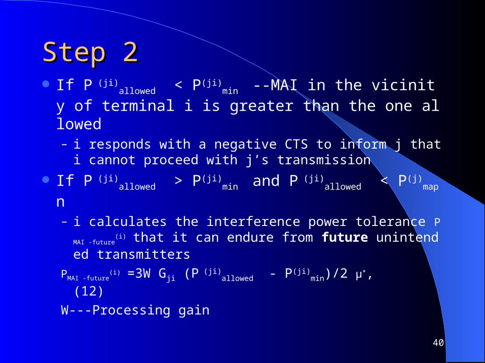
Step 2Step 2 If P
(ji)allowed < P(ji)
min --MAI in the vicinity of terminal i is greater than the one allowed – i responds with a negative CTS to inform j that i cannot
proceed with j’s transmission
If P (ji)
allowed > P(ji)min and P
(ji)allowed < P(j)
map n
– i calculates the interference power tolerance PMAI -future(i) th
at it can endure from future unintended transmitters
PMAI -future(i) =3W Gji (P
(ji)allowed - P(ji)
min)/2 μ*, (12)
W---Processing gain

41
Step 3Step 3 i equitably distributes this power tolerance among
future potentially interfering users in the vicinity of i(to prevent one neighbor from consuming the entire PMAI -future
(i) )– Calculate the number of terminals in the vicinity of i th
at are to share PMAI -future(i) : K(i) ,
K(i) = β (Kavg(i) - Kinst
(i) ), (if Kavg(i) > Kinst
(i) )
K(i) = β, otherwise (13)Kinst
(i) - the number of simultaneous transmissions in i’s neighborhood
Kavg(i) - average of Kinst
(i) ,β> 1 is a safety margin
42
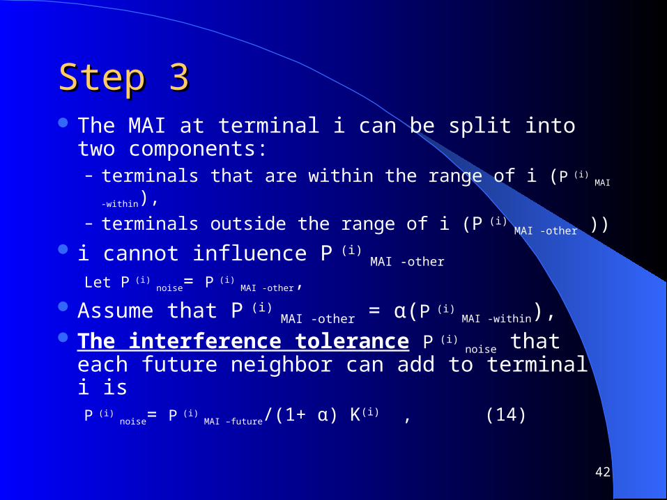
Step 3Step 3 The MAI at terminal i can be split into two
components:– terminals that are within the range of i (P
(i) MAI -within),
– terminals outside the range of i (P (i)
MAI -other ))
i cannot influence P (i)
MAI -other Let P
(i) noise= P
(i) MAI -other,
Assume that P (i)
MAI -other = α(P (i)
MAI -within), The interference tolerance P
(i) noise that each future
neighbor can add to terminal i isP
(i) noise= P
(i) MAI –future/(1+ α) K(i) , (14)

43
Step 3Step 3 When responding to j’s RTS,
– terminal i indicates in its CTS the power level P (ji)
allowed that j must use.
– i inserts P (i)
noise in the CTS packet and sends this packet back to terminal j at Pmax over the control channel using the common code.

44
Step 4Step 4
Compute P(s)map (Used in RTS)
Potentially interfering terminal s hears the CTS message from i, then
– compute the channel gain Gsi between s and i
– compute the maximum power P(s)map that s can use in its
future transmissions
P(s)map =min(P
(i) noise /Gsk ) for all neighbors k of s

45
Step 5,6Step 5,6 Step 5
– j send data to i Step 6
– If transmission is successful, receiver i responds j with an ACK packet over the data channel using the same power level that would have been used if i were to send a data packet to j.
46
Protocol RecoveryProtocol Recovery
while receiving a data packet, terminal i hears a RTS message (destined to any terminal) that contains an allowable power P(.)
map value that if used could cause an unacceptable interference with i’s ongoing reception. Then terminal i shall respond immediately with a special CTS packet over the control channel, preventing the RTS sender from commencing its transmission.

47
Protocol EvaluationProtocol Evaluation Evaluate both the network throughput and the ener
gy consumption of the CA-CDMA protocol and contrast it with the IEEE 802.11 scheme
Results are based on simulation experiments conducted using CSIM programs
Each node generates packets accordingto a Poisson process with rate λ
The routing overhead is ignored the maximum transmission range under the CA-C
DMA and 802.11 protocols is the same

48
Protocol EvaluationProtocol Evaluation
49
Simulation ResultsSimulation Results Consider two types of topologies: random grid and
clustered In the random grid topology, M mobile hosts are
placed across a square area of length 3000 meters. The square is split into M smaller squares.
Part (a) of the figure 6 depicts the network throughput. CA-CDMA achieves up to 280% increase over the throughput of the IEEE 802.11 scheme.
50
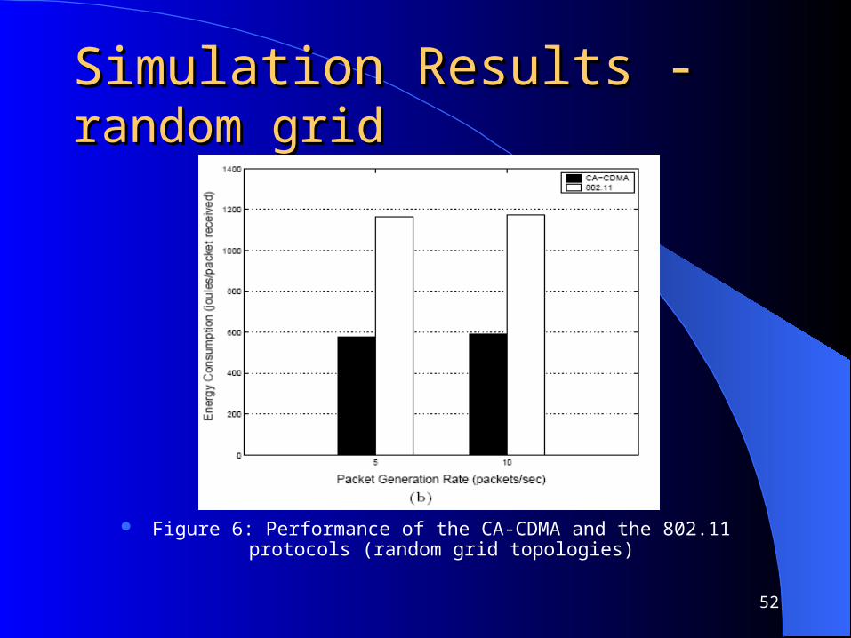
Simulation Results- Simulation Results- random random grid grid Part (b) of Figure 6 depicts the energy consumption
versusλ. CA-CDMA requires less than 50% of the energy required under the 802.11 scheme.
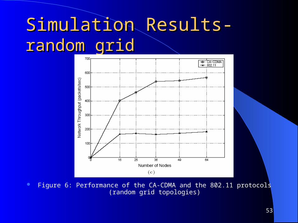
Part (c) of Figure 6 investigate the effect of varying the number of nodes. The throughput enhancement due to CA-CDMA increases with node density

51
Simulation Results- Simulation Results- random random grid grid
Figure 6: Performance of the CA-CDMA and the 802.11 protocols (random grid topologies)
52
Simulation Results -Simulation Results -random random grid grid
Figure 6: Performance of the CA-CDMA and the 802.11 protocols (random grid topologies)
53
Simulation Results- Simulation Results- random random grid grid
Figure 6: Performance of the CA-CDMA and the 802.11 protocols (random grid topologies)

54
Simulation ResultsSimulation Results- - clustered clustered topologytopology To generate a clustered topology, consider an area
of dimensions 1000 × 1000 (in meters). Let M = 24 nodes, which are split into 4 equal groups, each occupying a 100 × 100 square in one of the corners of the complete area.
For a given source node, the destination is selected from the same cluster with probability 1 − p or from a different cluster with probability p

55
Simulation ResultsSimulation Results- - clustered clustered topologytopology
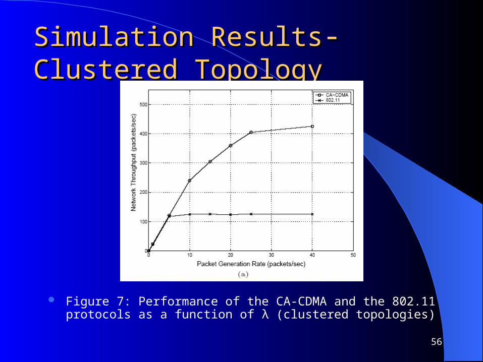
Part(a) of Figure 9 depicts the network throughput versusλ for p = 0.25. CA-CDMA makes three to four transmissions proceed simultaneously, results in a significant improvement in network throughput.
Part (b) of the figure investigate the locality of the traffic by fixing λ and varying p. As the traffic locality p increases the enhancement of CA-CDMA increases.
56
Simulation ResultsSimulation Results- - Clustered Clustered TopologyTopology
Figure 7: Performance of the CA-CDMA and the 802.11 protocols as a function of λ (clustered topologies)

57
Figure 7: Performance of the CA-CDMA and the 802.11 protocols as a function of λ (clustered topologies)
Simulation ResultsSimulation Results- - clustered clustered topologytopology

58
ConclusionsConclusions CA-CDMA accounts for the multiple access interf
erence, thereby solving the near-far problem that undermines the throughput performance in MANETs.
CA-CDMA uses channel-gain information obtained from overheard RTS and CTS packets over an out-of-band control channel to dynamically bound the transmission power of mobile terminals in the vicinity of a receiver.

59
ConclusionsConclusions
Adjusts the required transmission power for data packets to allow for interference-limited simultaneous transmissions to take place in the neighborhood of a receiving terminal
Simulation results showed that CA-CDMA can improve the network throughput by up to 280% and, achieve 50% reduction in the energy consumed

60
Future WorkFuture Work
Focus on other capacity optimizations such as the use of directional antennas in CDMA-based protocols