Embed Size (px)
Citation preview
1
CCNA 3 v3.1 Module 4
2
CCNA 3 Module 4
Switching Concepts

333
Switches and Bridges
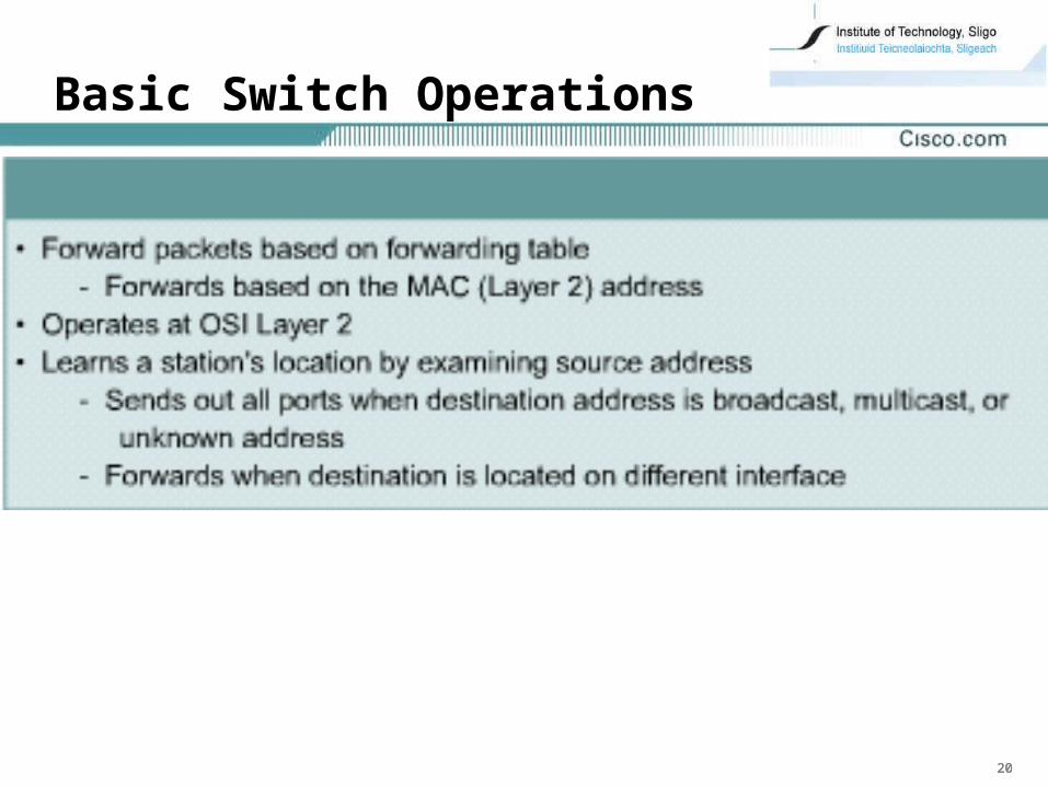
• Make decisions when frames are received
Select a path or circuit to send a frame to its destination
• Layer 2 devices
increases the number of collision domains
all hosts connected to the switch are still part of the same broadcast domain
• Used to
increase available bandwidth
reduce network congestion
• Switch segments a LAN into microsegments
segments with only a single host
Creates multiple collision-free domains
444
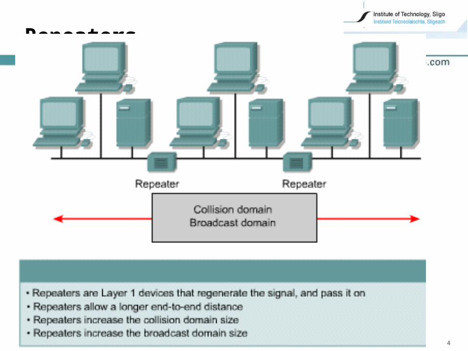
Repeaters
555
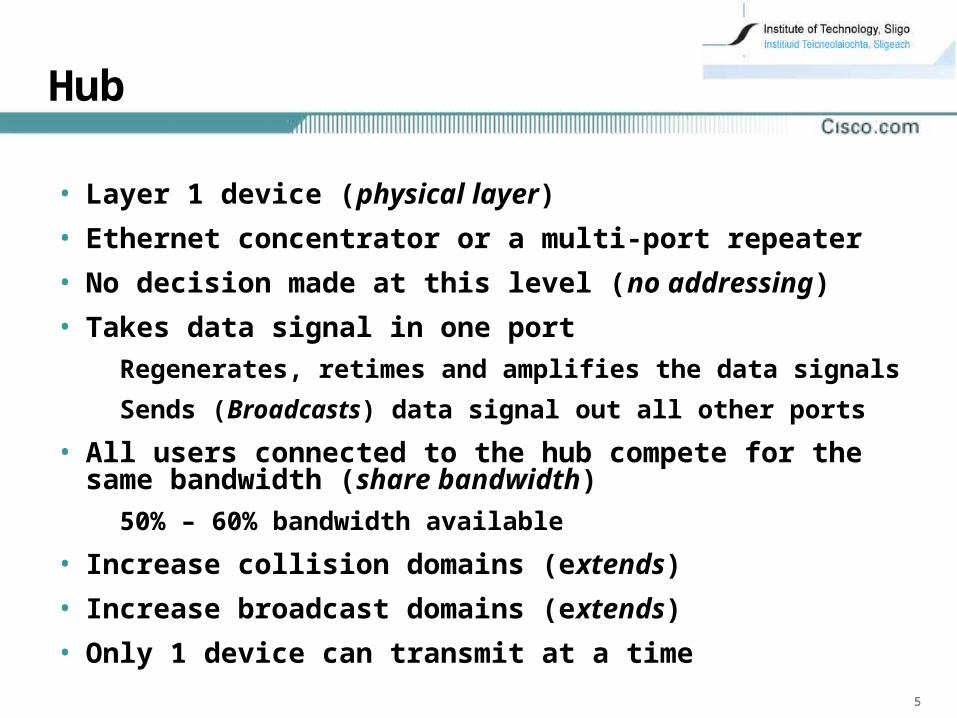
Hub
• Layer 1 device (physical layer)
• Ethernet concentrator or a multi-port repeater
• No decision made at this level (no addressing)
• Takes data signal in one port
Regenerates, retimes and amplifies the data signals
Sends (Broadcasts) data signal out all other ports
• All users connected to the hub compete for the same bandwidth (share bandwidth)
50% – 60% bandwidth available
• Increase collision domains (extends)
• Increase broadcast domains (extends)
• Only 1 device can transmit at a time
666
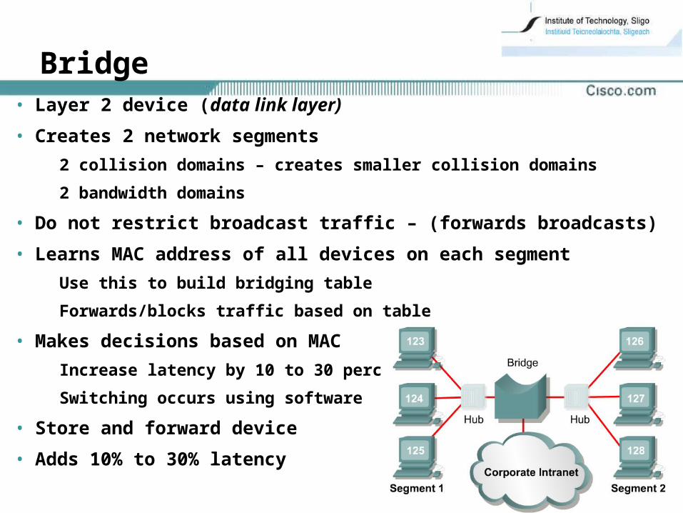
• Layer 2 device (data link layer)
• Creates 2 network segments
2 collision domains – creates smaller collision domains
2 bandwidth domains
• Do not restrict broadcast traffic – (forwards broadcasts)
• Learns MAC address of all devices on each segment
Use this to build bridging table
Forwards/blocks traffic based on table
• Makes decisions based on MAC
Increase latency by 10 to 30 percent
Switching occurs using software
• Store and forward device
• Adds 10% to 30% latency
Bridge
777
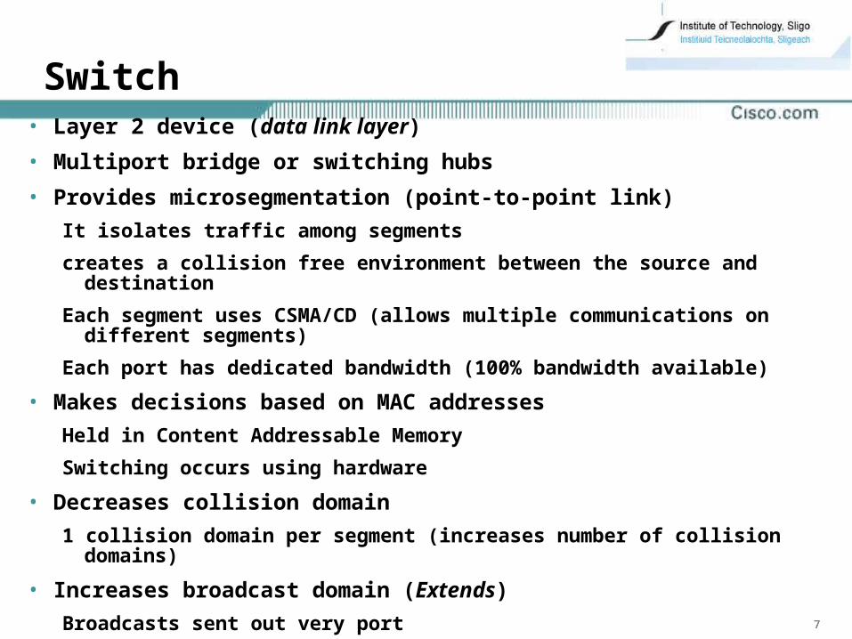
• Layer 2 device (data link layer)
• Multiport bridge or switching hubs
• Provides microsegmentation (point-to-point link)
It isolates traffic among segments
creates a collision free environment between the source and destination
Each segment uses CSMA/CD (allows multiple communications on different segments)
Each port has dedicated bandwidth (100% bandwidth available)
• Makes decisions based on MAC addresses
Held in Content Addressable Memory
Switching occurs using hardware
• Decreases collision domain
1 collision domain per segment (increases number of collision domains)
• Increases broadcast domain (Extends)
Broadcasts sent out very port
Switch
888
• Layer 3 device (network layer)
• Makes decisions based on network addresses
IP Address
• Routing tables
List of Layer 3 network address and the port to go out on
• Router Purpose
Examine incoming packets of Layer 3 data
Choose the best path for them through the network
Switch them to the proper outgoing port
• Reduces
Broadcast domain
Collision domain
Router
999
Network Performance• LANs are increasingly congested and overburdened
Growing population of network users
Multitasking environment
increased demand for network resources
The use of network intensive applications
e.g. WWW, multi media, e-mail
Client/server applications
• This has resulted in
a need for more bandwidth
slower response times
longer file transfers
network users becoming less productive
101010
Elements of Ethernet 802.3
• Used to transport data between devices on a network (computers, printers, and file servers)
• Multi-access broadcast technology
Shared media
• Uses CSMA/CD to allows one station transmit at a time
• Latency as frames travel across media
• Repeaters extend distances (increase latency)
• Layer 2 devices improve performance
111111
Network Latency• Latency, or delay, is the time a frame or a packet takes
to travel from the source to the final destination
• Latency sources:
NIC Delay
The time it takes the source NIC to place voltage pulses on the wire and the time it takes the receiving NIC to interpret these pulses
1 microsecond for a 10BASE-T NIC
Propagation delay
Signal takes time to travel along the cable
About 0.556 microseconds per 100 m for Cat 5 UTP
Networking devices
Layer 1 no decisions less latency
Layer 2 devices make layer 2 decisions increased latency
Layer 3 devices make layer 3 decisions most latency

121212
Ethernet ?-BaseT Transmission• The time it takes a frame to be transmitted
Number of bits being sent * Technology Bit time
• 10 Mbps Ethernet bit has a 100 ns transmission window (bit time of 100 ns)
A byte equals 8 bits
1 byte is 8bits * 100ns = 800 ns to transmit
• 100Mbps – 10ns
• 1000Mbps – 1ns
131313
• Attenuation means that the signal weakens as it travels through the network
The resistance in the cable causes loss of signal strength
141414
Half Duplex Ethernet•A host could transmit or receive at one time, but not both•Before transmitting
Host checks media for signalIf no signal message is transmittedIf signal exists the transmission is delayed
•If two or more hosts transmit at the same timeA collision occursJam signal setHosts stop sendingRun a back-off algorithm to generate a random delayWait for the random delay before attempting to retransmit
•Only 1 host can transmit at a time•50% - 60% bandwidth available
151515
Full Duplex Transmission
• Transmission and receipt of packets at the same time
Use of two pairs of wires in the cable and a switched connection between each node
Point-to-point connection
dedicated connection to switch port
Collision free – 2 hosts can send simultaneously
No negotiation for bandwidth
• Full-duplex connections can use
10BASE-T, 100BASE-TX, or 100BASE-FX
• NIC must have half duplex capabilities
• Full-duplex Ethernet offers
100% of the bandwidth in both directions
potential 20 Mbps throughput -10 Mbps TX and 10 Mbps RX
161616
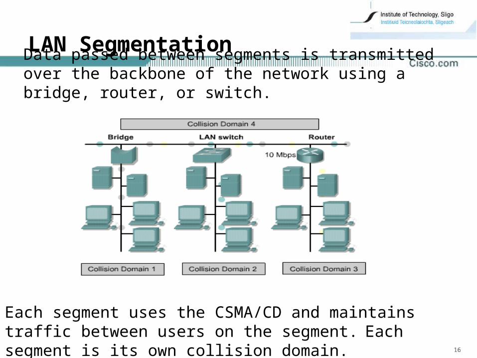
LAN Segmentation
Each segment uses the CSMA/CD and maintains traffic between users on the segment. Each segment is its own collision domain.
Data passed between segments is transmitted over the backbone of the network using a bridge, router, or switch.
171717
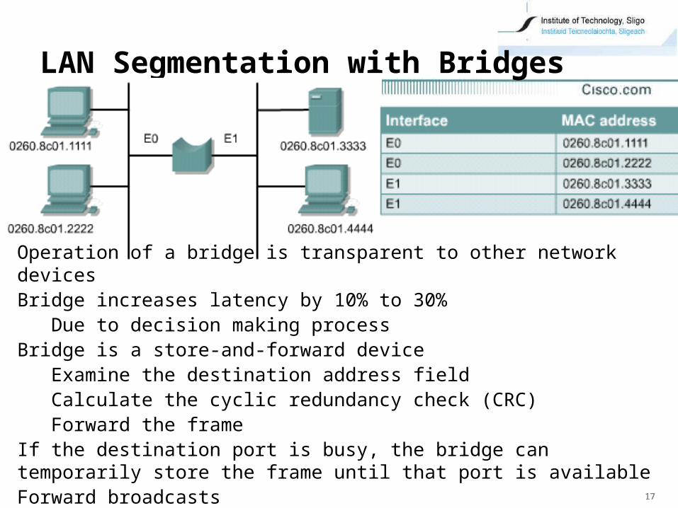
LAN Segmentation with Bridges
Operation of a bridge is transparent to other network devicesBridge increases latency by 10% to 30%
Due to decision making processBridge is a store-and-forward device
Examine the destination address field Calculate the cyclic redundancy check (CRC) Forward the frame
If the destination port is busy, the bridge can temporarily store the frame until that port is availableForward broadcasts

181818
LAN Segmentation using Routers
Provide segmentation of networksLatency is increased by 20% to 30% over a switched network
router operates at the network layerUses IP address to determine the best path to destination
Provide connectivity between networks and subnetworksRouters also do not forward broadcasts
191919
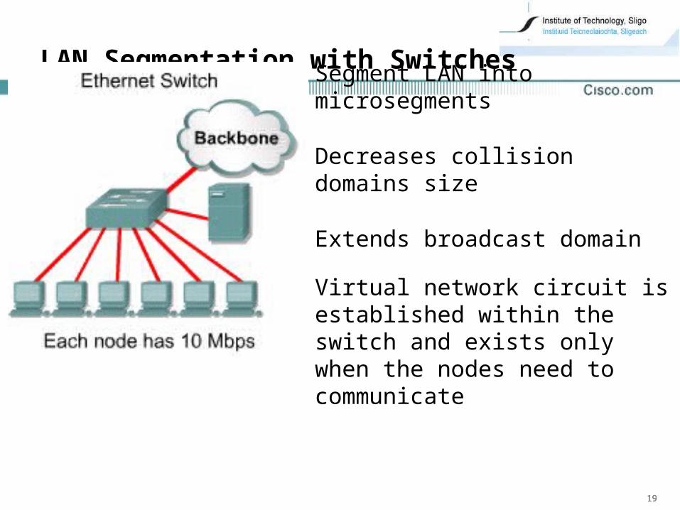
LAN Segmentation with Switches
Segment LAN into microsegments
Decreases collision domains size
Extends broadcast domain
Virtual network circuit is established within the switch and exists only when the nodes need to communicate
202020
Basic Switch Operations
212121
Switching
• receiving incoming frame on one interface and delivering that frame out another interface
• Routers use Layer 3 switching to route a packet
Based on network address/ ip address
Hierarchical addressing – more security and flow control
• Switches use Layer 2 switching to forward frames
based on destination MAC address information
If it does not know where to send the frame, it broadcasts the frame out all ports to the network
When a reply is returned, the switch records the new address in the CAM.
222222
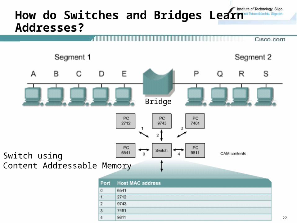
How do Switches and Bridges Learn Addresses?
Bridge
Switch usingContent Addressable Memory
232323
• Bridges and switches learn in the following ways:
Reading the source MAC address of each received frame/datagram
Recording the port on which the MAC address was received.
• Bridge/Switch learns which devices are connected to each port
• The device MAC addresses and port are stored in the addressing table (Content Addressable Memory)
• When a packet arrives
Host and destination address information is identified
CAM stores host MAC addresses and associated port numbers
Addresses are learned dynamically
At each store it is stamped and will be held for a set time period
If it is not stamped within the time period it is removed from CAM
Destination address is compared with a CAM
If there is a match, and the outgoing port is the same as the incoming port the packet is discarded
If there is a match, and the outgoing and incoming ports are different the packet is forwarded out the outgoing port
If there is no match, packet is forwarded out all ports except the port it was received on (flooding)
242424
How do Switches and Bridges Filter Frames
• Bridges are capable of filtering frames based on any Layer 2 fields
• Bridge can be programmed to reject/not forward
All frames sourced from a particular network
Based on upper network layer protocols
filters out unnecessary broadcast and multicast packets
• Ignoring a frame is called filtering.
• Copying the frame is called forwarding.
252525
Symmetric and Asymmetric Switching
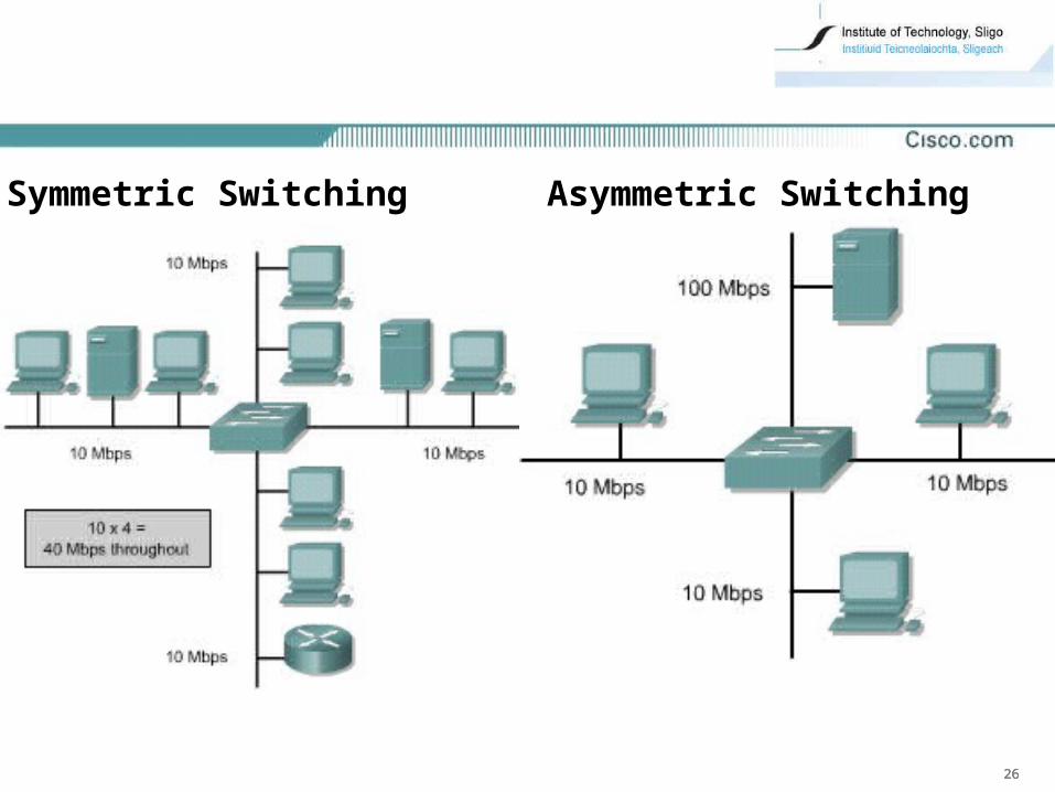
• based on the way bandwidth is allocated to the switch ports
• Symmetric switch
switched connections between ports with the same bandwidth (all 10Mbps or all 100Mbps)
• Asymmetric switch
switched connections between ports of unlike bandwidth
combination of 10 and 100 Mbps ports
Enables more bandwidth to be dedicated to the server switch port in order to prevent a bottleneck
Memory buffering is required (keeps the frames contiguous between different data rate ports)
262626
Symmetric Switching Asymmetric Switching
272727
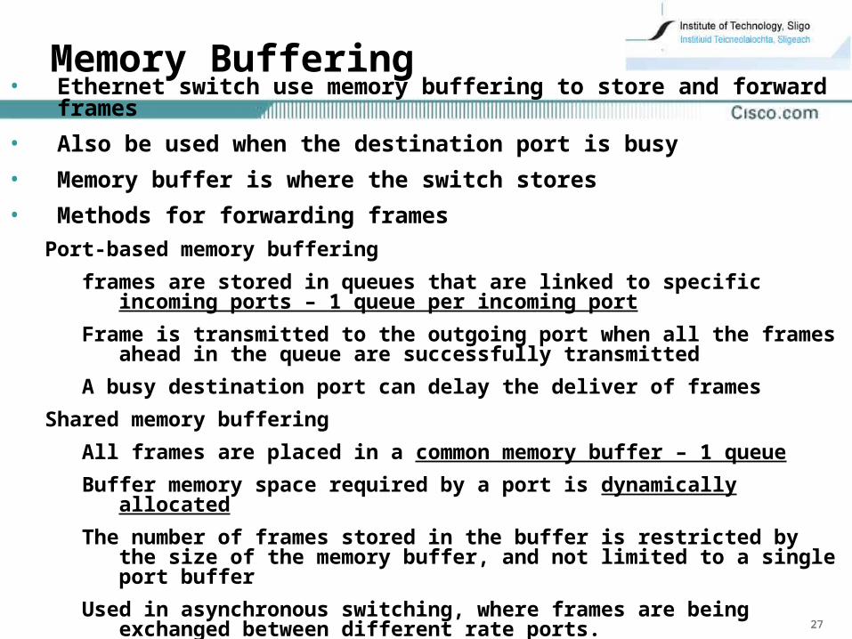
Memory Buffering• Ethernet switch use memory buffering to store and forward
frames
• Also be used when the destination port is busy
• Memory buffer is where the switch stores
• Methods for forwarding frames
Port-based memory buffering
frames are stored in queues that are linked to specific incoming ports – 1 queue per incoming port
Frame is transmitted to the outgoing port when all the frames ahead in the queue are successfully transmitted
A busy destination port can delay the deliver of frames
Shared memory buffering
All frames are placed in a common memory buffer – 1 queue
Buffer memory space required by a port is dynamically allocated
The number of frames stored in the buffer is restricted by the size of the memory buffer, and not limited to a single port buffer
Used in asynchronous switching, where frames are being exchanged between different rate ports.
282828
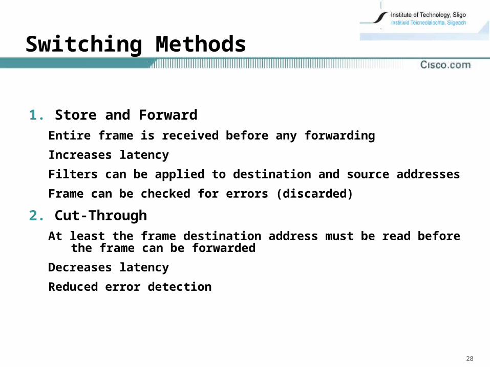
Switching Methods
1. Store and Forward
Entire frame is received before any forwarding
Increases latency
Filters can be applied to destination and source addresses
Frame can be checked for errors (discarded)
2. Cut-Through
At least the frame destination address must be read before the frame can be forwarded
Decreases latency
Reduced error detection
292929
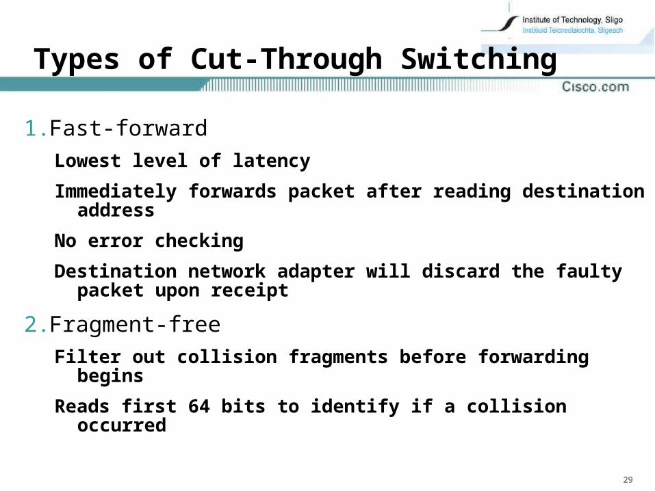
Types of Cut-Through Switching
1. Fast-forward
Lowest level of latency
Immediately forwards packet after reading destination address
No error checking
Destination network adapter will discard the faulty packet upon receipt
2. Fragment-free
Filter out collision fragments before forwarding begins
Reads first 64 bits to identify if a collision occurred
303030
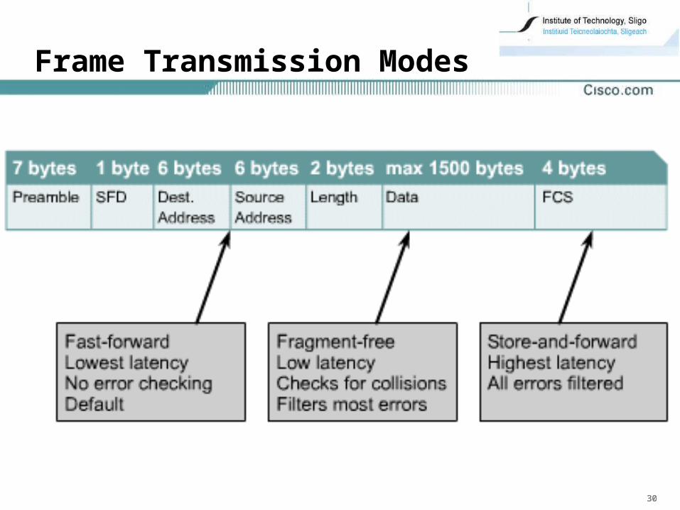
Frame Transmission Modes
313131
Hybrid Transmission Mode
• Combination of cut-through and store-and-forward
• Called adaptive cut-through or error sensing
• Uses cut-through until it detects a given number of errors
• Once the error threshold is reached, the switch changes to store-and-forward mode
323232
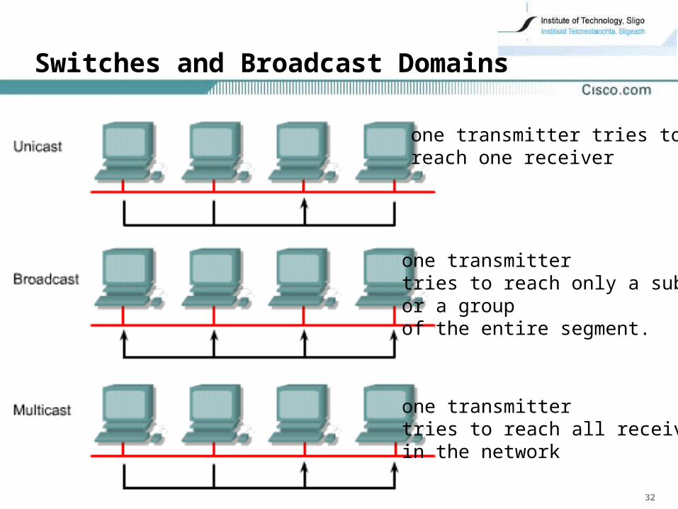
Switches and Broadcast Domains
one transmitter tries toreach one receiver
one transmitter tries to reach only a subsetor a groupof the entire segment.
one transmittertries to reach all receiversin the network
333333
• When a device wants to send out a Layer 2 broadcast
Destination MAC address in the frame is set to all ones
FF:FF:FF:FF:FF:FF in hexadecimal
MAC broadcast domain
• When a switch receives a broadcast
it forwards it to each port on the switch except the incoming port
Each attached device must process the broadcast frame
• Broadcasts reduce available bandwidth