Embed Size (px)
Citation preview
1
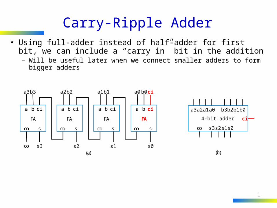
Carry-Ripple Adder• Using full-adder instead of half-adder for first bit, we can
include a “carry in” bit in the addition– Will be useful later when we connect smaller adders to form bigger
adders
a3
co s
FA
co
b3 a2b2
s3 s2 s1
ciba
co s
FA
ciba
a1b1
co s
FA
ciba
s0
a0b0 ci
co s
FA
ciba
(a)
a3a2a1a0 b3
s3s2s1s0co
ci
b2b1b0
(b)
4-bit adder
2
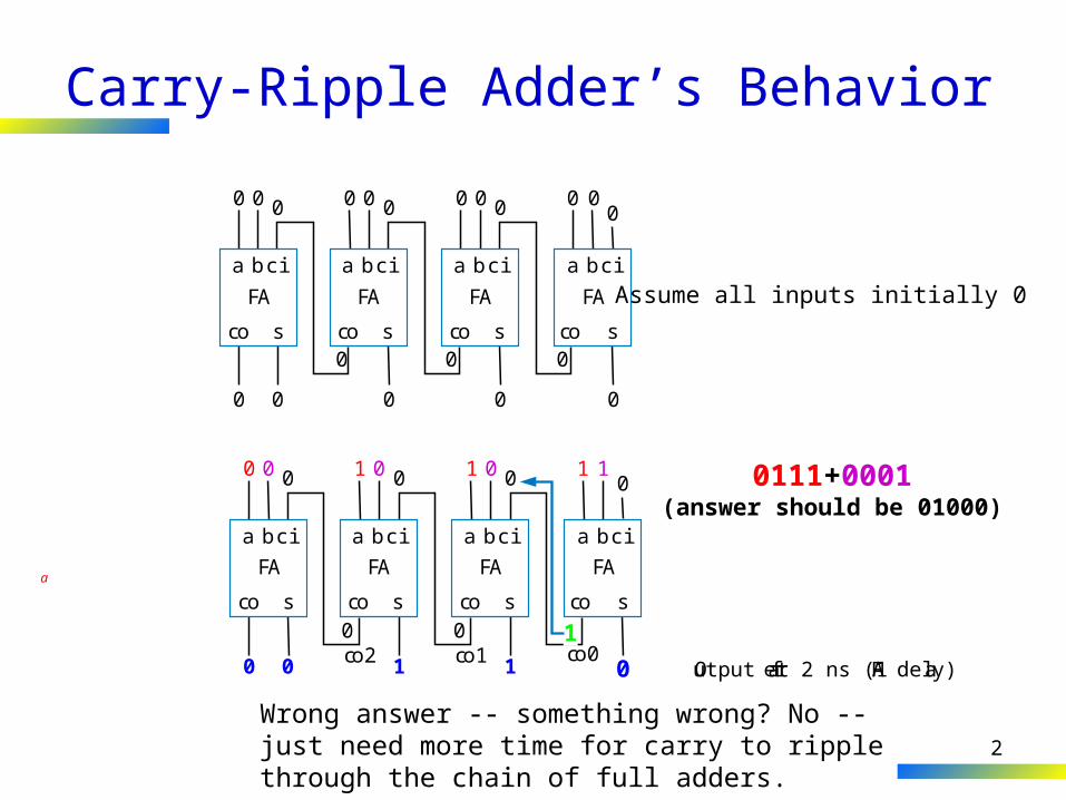
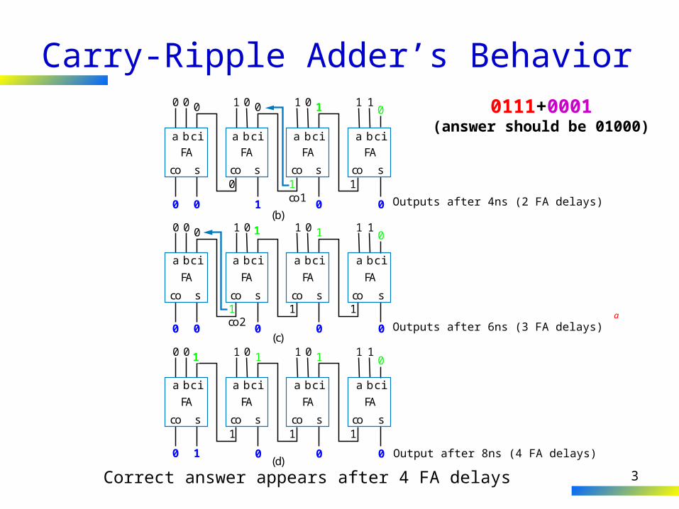
Carry-Ripple Adder’s Behavior
0 1 1 10 0 0 1 0111+0001(answer should be 01000)
0
co s
FA
0 0
0 0 0
0 0 00 0 0
0 0
ciba
co s
FA
ciba
0 0
co s
FA
ciba
0
0 0
co s
FA
ciba
0
Assume all inputs initially 0
Output after 2 ns (1FA delay)0 0 1 1 0
co s
FA
0 0
0 0 0
co2 co1 co0
ciba
co s
FA
ciba
co s
FA
ciba
co s
FA
ciba
0
01
Wrong answer -- something wrong? No -- just need more time for carry to ripple through the chain of full adders.
a
3
0 00
co s
FA
1 1 1
1 10 1 0
ciba
co s
FA
ciba
1 0
co s
FA
ciba
0 0 0
1 1
co s
FA
ciba
(d)Output after 8ns (4 FA delays)
Carry-Ripple Adder’s Behavior0
co s
FA
0 0 1
co1
0 1 0
ciba
co s
FAciba
1 0
co s
FAciba
0 0 1 0 0
1 1
co s
FAciba
(b)
10 1
0 0 0
0
1
0 1
1
Outputs after 4ns (2 FA delays)
00
co s
FA
1 1
0 1
co2
0 1 0
ciba
co s
FA
ciba
1 0
co s
FA
ciba
0 0
1 10
co s
FA
ciba
(c)Outputs after 6ns (3 FA delays)
a
0111+0001(answer should be 01000)
1
Correct answer appears after 4 FA delays
4
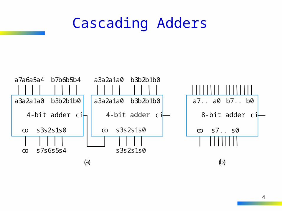
Cascading Adders
a3a2a1a0 b3
s3s2s1s0co
s7s6s5s4co
ci
b2b1b0
a7a6a5a4 b7b6b5b4
(a) (b)
4-bit adder
a3a2a1a0 b3
s3s2s1s0
s3s2s1s0
co
ci
b2b1b0
a3a2a1a0 b3b2b1b0
4-bit adder
a7.. a0 b7.. b0
s7.. s0co
ci8-bit adder
5
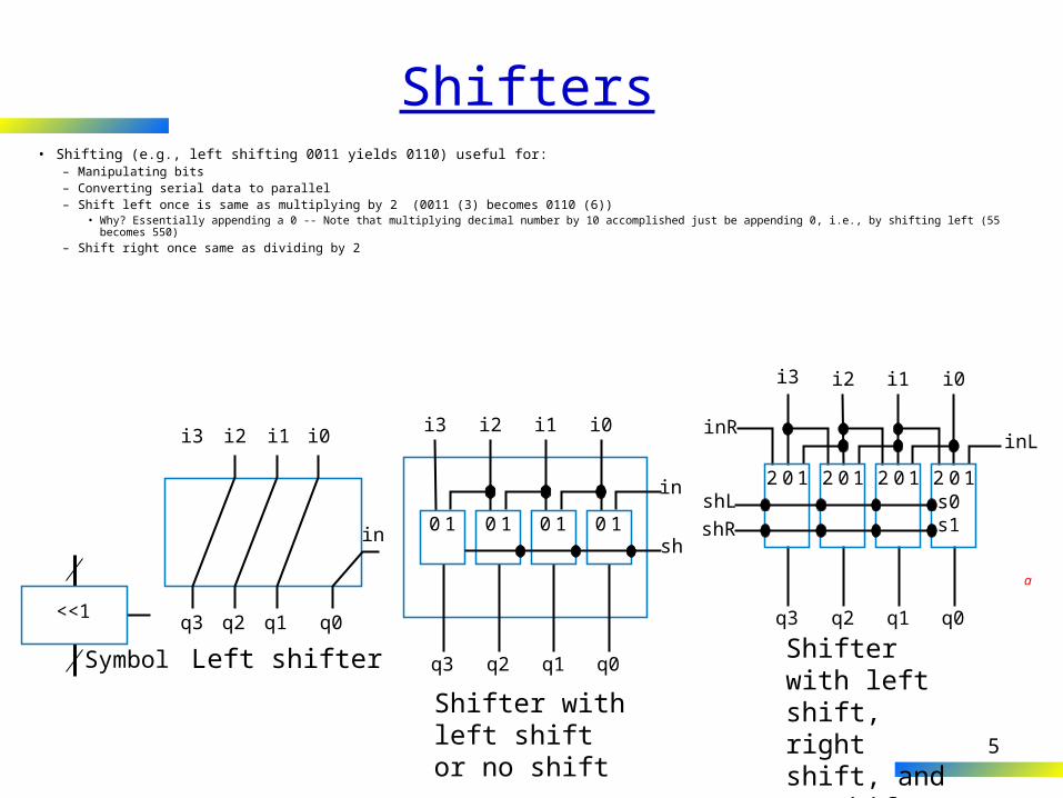
Shifters• Shifting (e.g., left shifting 0011 yields 0110) useful for:
– Manipulating bits– Converting serial data to parallel– Shift left once is same as multiplying by 2 (0011 (3) becomes 0110 (6))
• Why? Essentially appending a 0 -- Note that multiplying decimal number by 10 accomplished just be appending 0, i.e., by shifting left (55 becomes 550)
– Shift right once same as dividing by 2
i2
q3 q2 q1 q0
in
i3 i1 i0
Left shifter
0 1 0 1 0 1 0 1
in
sh
i3
q3 q2 q1 q0
i2 i1 i0
Shifter with left shift or no shift
inL
i3
q3 q2 q1 q0
i2 i1 i0
inR
2 0s0s1
shLshR
1 2 01 2 01 2 01
Shifter with left shift, right shift, and no shift
<<1
Symbol
a
6
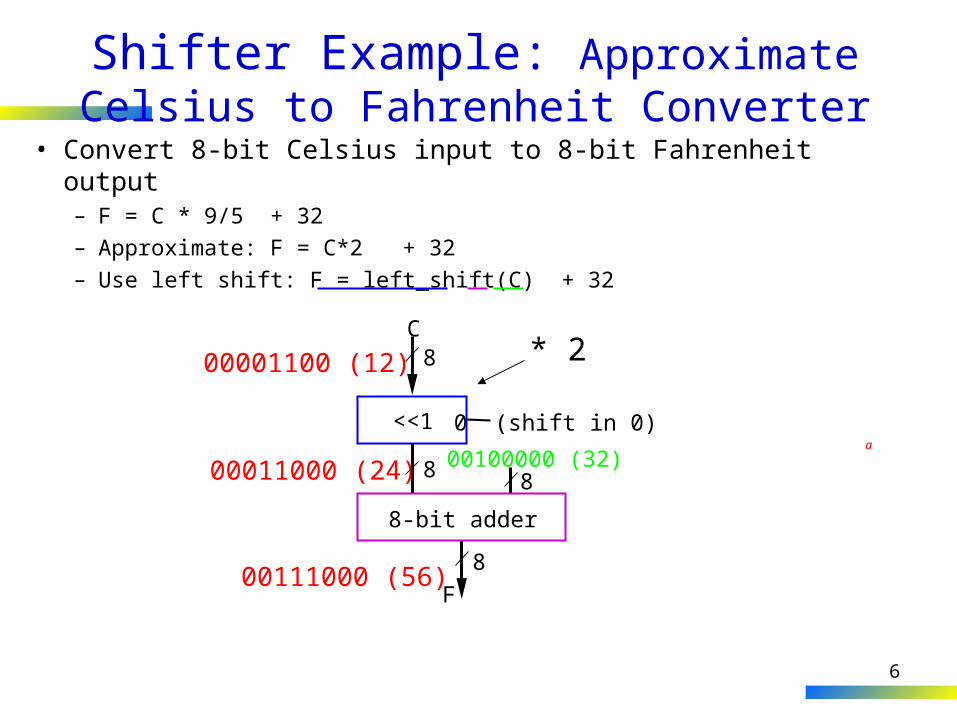
Shifter Example: Approximate Celsius to Fahrenheit Converter
• Convert 8-bit Celsius input to 8-bit Fahrenheit output– F = C * 9/5 + 32– Approximate: F = C*2 + 32 – Use left shift: F = left_shift(C) + 32
C800001100 (12)
00011000 (24)
00111000 (56)
<<1 0 (shift in 0)
8F
8-bit adder
8 800100000 (32)
* 2
a
7
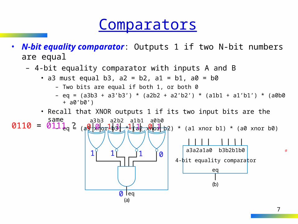
Comparators• N-bit equality comparator: Outputs 1 if two N-bit numbers are equal
– 4-bit equality comparator with inputs A and B• a3 must equal b3, a2 = b2, a1 = b1, a0 = b0
– Two bits are equal if both 1, or both 0
– eq = (a3b3 + a3’b3’) * (a2b2 + a2’b2’) * (a1b1 + a1’b1’) * (a0b0 + a0’b0’)
• Recall that XNOR outputs 1 if its two input bits are the same– eq = (a3 xnor b3) * (a2 xnor b2) * (a1 xnor b1) * (a0 xnor b0)
a3b3 a2b2 a1b1 a0b0
eq(a)
(b)
a3a2a1a0 b3
eq
b2b1b0
4-bit equality comparator
a
0110 = 0111 ? 0 1 1 00 1 1 1
01 1 1
0
8
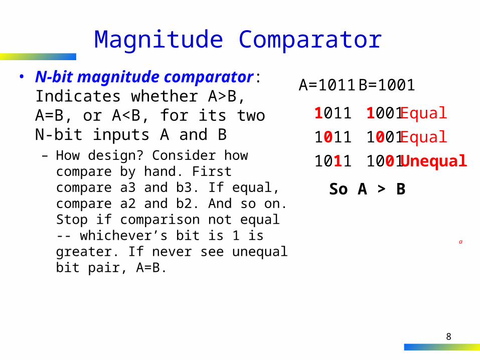
Magnitude Comparator• N-bit magnitude comparator:
Indicates whether A>B, A=B, or A<B, for its two N-bit inputs A and B– How design? Consider how compare
by hand. First compare a3 and b3. If equal, compare a2 and b2. And so on. Stop if comparison not equal -- whichever’s bit is 1 is greater. If never see unequal bit pair, A=B.
A=1011 B=1001
1011 1001
a
Equal
1011 1001 Equal
1011 1001 Unequal
So A > B
9
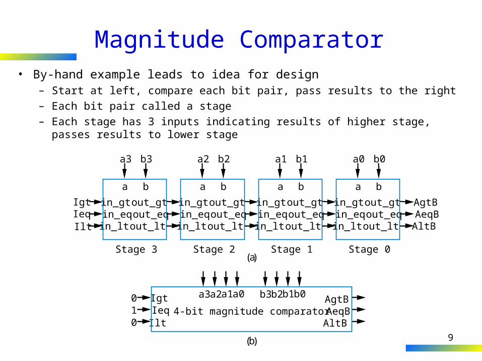
Magnitude Comparator• By-hand example leads to idea for design
– Start at left, compare each bit pair, pass results to the right
– Each bit pair called a stage
– Each stage has 3 inputs indicating results of higher stage, passes results to lower stage
IgtIeqIlt
a3a2a1a0 b3b2b1b0 AgtBAeqBAltB
in_gtin_eqin_lt
out_gtout_eqout_lt
IgtIeqIlt
Stage 3
a3 b3
a b
in_gtin_eqin_lt
out_gtout_eqout_lt
Stage 2
a2 b2
a b
in_gtin_eqin_lt
out_gtout_eqout_lt
Stage 1
a1 b1
a b
in_gtin_eqin_lt
out_gtout_eqout_lt
AgtBAeqBAltB
Stage 0
a0 b0
a b
(a)
(b)
0
01 4-bit magnitude comparator
10
Magnitude Comparator
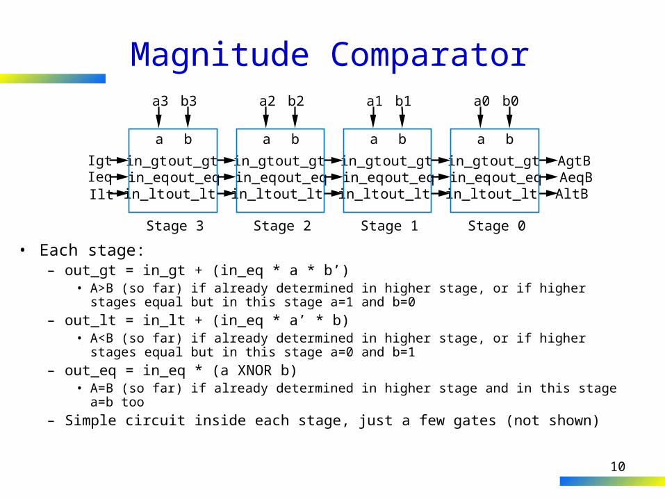
• Each stage:– out_gt = in_gt + (in_eq * a * b’)
• A>B (so far) if already determined in higher stage, or if higher stages equal but in this stage a=1 and b=0
– out_lt = in_lt + (in_eq * a’ * b)• A<B (so far) if already determined in higher stage, or if higher stages equal but in
this stage a=0 and b=1
– out_eq = in_eq * (a XNOR b)• A=B (so far) if already determined in higher stage and in this stage a=b too
– Simple circuit inside each stage, just a few gates (not shown)
in_gtin_eqin_lt
out_gtout_eqout_lt
IgtIeqIlt
Stage 3
a3 b3
a b
in_gtin_eqin_lt
out_gtout_eqout_lt
Stage 2
a2 b2
a b
in_gtin_eqin_lt
out_gtout_eqout_lt
Stage 1
a1 b1
a b
in_gtin_eqin_lt
out_gtout_eqout_lt
AgtBAeqBAltB
Stage 0
a0 b0
a b
11
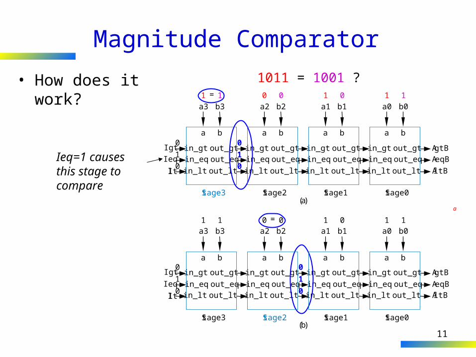
Magnitude Comparator
• How does it work?
in_gtin_eq
in_lt
out_gtout_eq
out_lt
IgtIeq
Ilt
Stage3
a3 b3
a b
in_gtin_eq
in_lt
out_gtout_eq
out_lt
Stage2
a2 b2
a b
in_gtin_eq
in_lt
out_gtout_eq
out_lt
Stage1
a1 b1
a b
in_gtin_eq
in_lt
out_gtout_eq
out_lt
AgtBAeqB
AltB
Stage0
a0 b01 1 0 0 1 0 1 1
a b
(a)
=
0
1
0
in_gt
in_eqin_lt
out_gt
out_eqout_lt
Igt
Ieq
Ilt
Stage3
a3 b3
a b
in_gt
in_eqin_lt
out_gt
out_eqout_lt
Stage2
a2 b2
a b
in_gt
in_eqin_lt
out_gt
out_eqout_lt
Stage1
a1 b1
a b
in_gt
in_eqin_lt
out_gt
out_eqout_lt
AgtB
AeqBAltB
Stage0
a0 b01 1 0 0 1 0 1 1
a b
(b)
0
1
0
=
0
1
0
1011 = 1001 ?
0
1
0Ieq=1 causes this stage to compare
a
12
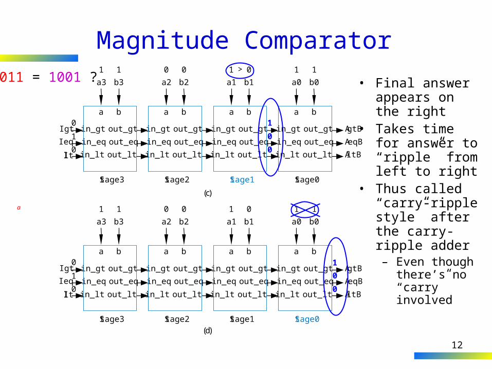
Magnitude Comparator
• Final answer appears on the right
• Takes time for answer to “ripple” from left to right
• Thus called “carry-ripple style” after the carry-ripple adder– Even though
there’s no “carry” involved
1011 = 1001 ?
in_gt
in_eq
in_lt
out_gt
out_eq
out_lt
Igt
Ieq
Ilt
Stage3
a3 b3
a b
in_gt
in_eq
in_lt
out_gt
out_eq
out_lt
Stage2
a2 b2
a b
in_gt
in_eq
in_lt
out_gt
out_eq
out_lt
Stage1
a1 b1
a b
in_gt
in_eq
in_lt
out_gt
out_eq
out_lt
AgtB
AeqB
AltB
Stage0
a0 b0
1 1 0 0 1 0 1 1
a b
(c)
0
1
0
1
0
0
>
in_gt
in_eq
in_lt
out_gt
out_eq
out_lt
Igt
Ieq
Ilt
Stage3
a3 b3
a b
in_gt
in_eq
in_lt
out_gt
out_eq
out_lt
Stage2
a2 b2
a b
in_gt
in_eq
in_lt
out_gt
out_eq
out_lt
Stage1
a1 b1
a b
in_gt
in_eq
in_lt
out_gt
out_eq
out_lt
AgtB
AeqB
AltB
Stage0
a0 b0
1 1 0 0 1 0 1 1
a b
(d)
0
1
0
0
1
0
a
13
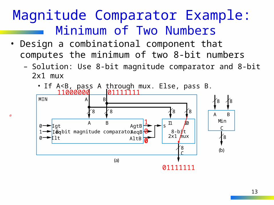
Magnitude Comparator Example: Minimum of Two Numbers
• Design a combinational component that computes the minimum of two 8-bit numbers– Solution: Use 8-bit magnitude comparator and 8-bit 2x1 mux
• If A<B, pass A through mux. Else, pass B.
MIN
IgtIeqIlt
AgtBAeqBAltB
010
A
A B
B
8-bit magnitude comparators I1 I0
2x1 mux8-bit
C
8
88 8 8
8
8
8
C
A BMin
(a)
(b)
11000000 01111111
0
01
01111111
a
14
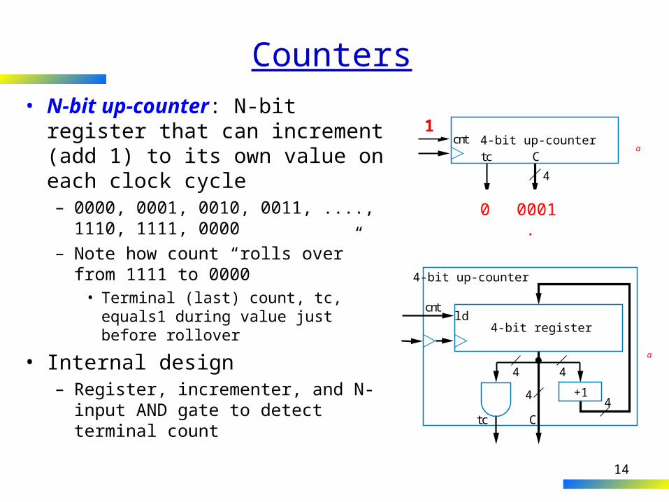
Counters• N-bit up-counter: N-bit register
that can increment (add 1) to its own value on each clock cycle– 0000, 0001, 0010, 0011, ...., 1110,
1111, 0000– Note how count “rolls over” from 1111
to 0000• Terminal (last) count, tc, equals1
during value just before rollover
• Internal design– Register, incrementer, and N-input
AND gate to detect terminal count
cnttc C
4-bit up-counter
4
0000
01
00010010001101000101...11100 111110 00000001
ld4-bit register
Ctc
4
4 4
4
cnt
4-bit up-counter
+1
a
a
15
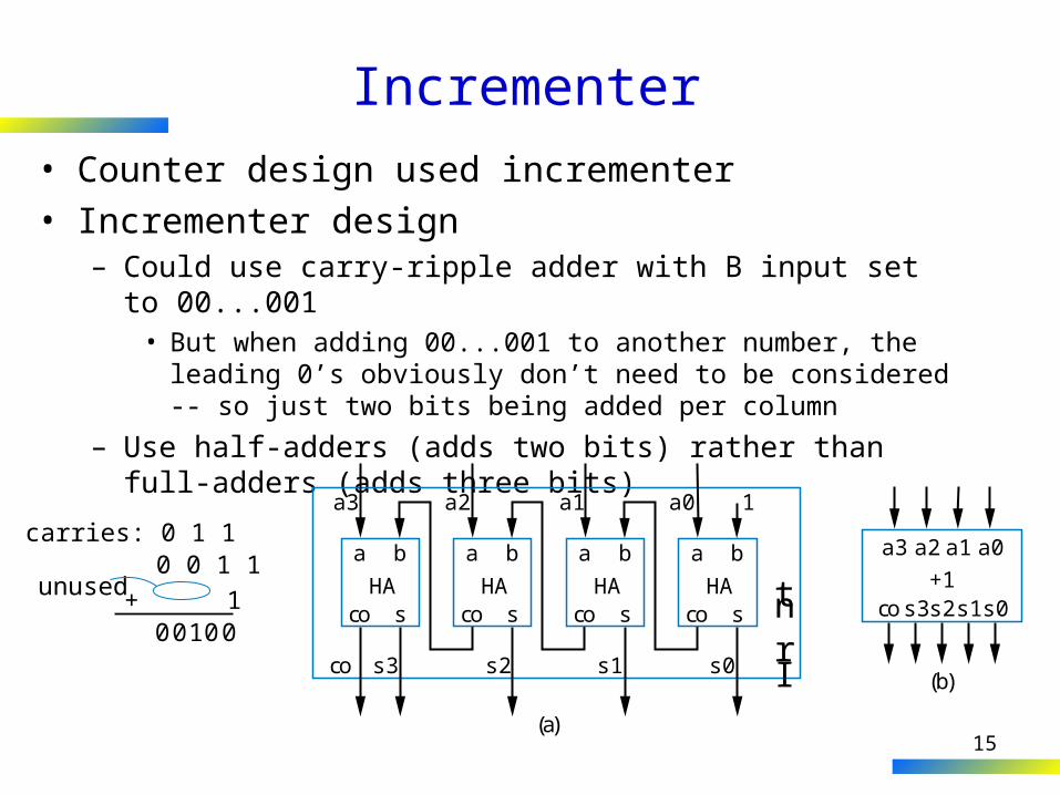
Incrementer• Counter design used incrementer• Incrementer design
– Could use carry-ripple adder with B input set to 00...001• But when adding 00...001 to another number, the leading 0’s
obviously don’t need to be considered -- so just two bits being added per column
– Use half-adders (adds two bits) rather than full-adders (adds three bits)
0 0 1 10 1 1
1+
carries:
unused
0000 1
(a)
(b)
a3 a2 a1 a0 1
s0s1s2s3co
a b
co sHA
a b
co sHA
a b
co sHA
a b
co sHA
Irnt
a3
cos3s2+1
s1s0
a2 a1 a0
16
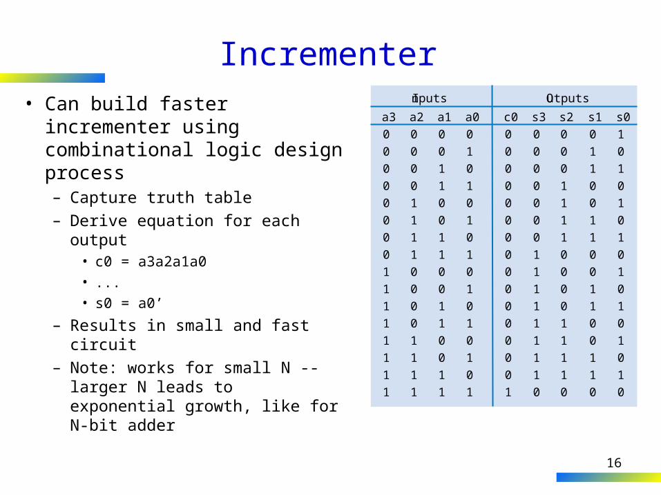
Incrementer• Can build faster incrementer
using combinational logic design process– Capture truth table– Derive equation for each output
• c0 = a3a2a1a0
• ...
• s0 = a0’
– Results in small and fast circuit– Note: works for small N -- larger
N leads to exponential growth, like for N-bit adder
s20001111000011110
s10110011001100110
s01010101010101010
s30000000111111110
c00000000000000001
a00101010101010101
a10011001100110011
a30000000011111111
Inputs Outputs
a20000111100001111
17
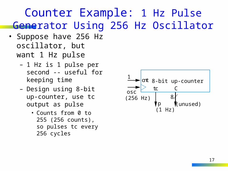
Counter Example: 1 Hz Pulse Generator Using 256 Hz Oscillator
• Suppose have 256 Hz oscillator, but want 1 Hz pulse– 1 Hz is 1 pulse per second
-- useful for keeping time– Design using 8-bit up-
counter, use tc output as pulse
• Counts from 0 to 255 (256 counts), so pulses tc every 256 cycles
cnt
tc C
(unused)
8-bit up-counter1
osc(256 Hz) 8
p(1 Hz)
18
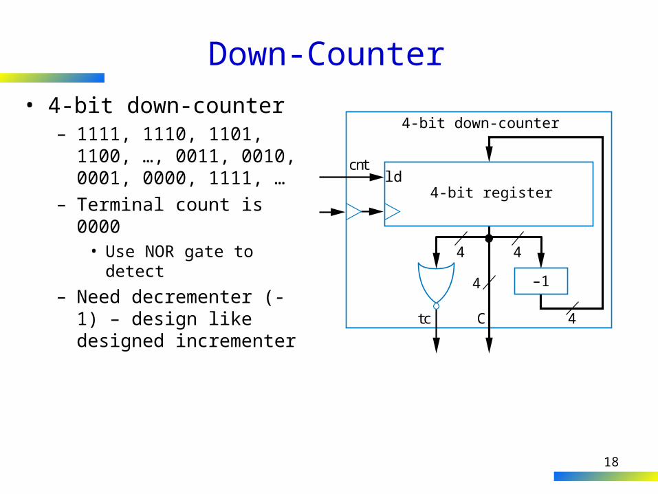
Down-Counter• 4-bit down-counter
– 1111, 1110, 1101, 1100, …, 0011, 0010, 0001, 0000, 1111, …
– Terminal count is 0000• Use NOR gate to detect
– Need decrementer (-1) – design like designed incrementer
ld4-bit register
Ctc
4
4 4
4
cnt
4-bit down-counter
–1
19
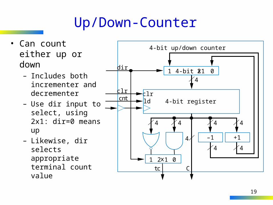
Up/Down-Counter• Can count either up
or down– Includes both
incrementer and decrementer
– Use dir input to select, using 2x1: dir=0 means up
– Likewise, dir selects appropriate terminal count value
ld 4-bit register
Ctc
4
44 44
4
cntclrclr
dir
4-bit up/down counter
4 4
–1 +1
1 02x1
1 04-bit 2x1
20
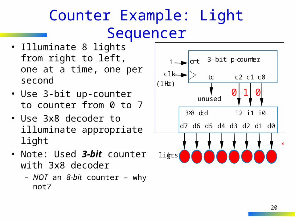
Counter Example: Light Sequencer• Illuminate 8 lights from right
to left, one at a time, one per second
• Use 3-bit up-counter to counter from 0 to 7
• Use 3x8 decoder to illuminate appropriate light
• Note: Used 3-bit counter with 3x8 decoder– NOT an 8-bit counter – why
not?
lights
0 0 00 0 10 1 0
3-bit up-countercnt
tc c2 c1 c0
3x8 dcd i2 i1 i0
unused
1
clk
(1Hz)
d7 d6 d5 d4 d3 d2 d1 d0
a