Embed Size (px)
Citation preview
© 2016 Imtex Membranes Corp | +1 (905) 363-0111Imtex International SEZC Ltd. | +1 (345) 815-3986
IMTEX PERMYLENE™ MEMBRANE SYSTEMS
PermyleneTM Integrated Solutions1-Butene Purification
from C4 Raffinate
Innovative Membrane Technologies
Permylene™ Integrated Solutions 1-Butene Purification from C4 Raffinate
© 2016 Imtex Membranes Corp | +1 (905) 363-0111Imtex International SEZC Ltd. | +1 (345) 815-3986
TABLE OF CONTENTS INTRODUCTION AND BACKGROUND – 1
THE CONVENTIONAL APPROACH TO BUTENE PRODUCTION – 2Case Study Details – 2
Distillation Process System Design – 3Capital and Energy Costs for Distillation – 4
PERMYLENE TECHNOLOGY – A COST EFFECTIVE ALTERNATIVE – 4Permylene System Configuration and Performance – 6Process Design and Integration – 7Permylene System Costs and Project Economics – 8Other C4 Applications and Olefin Concentrations – 9
SUMMARY – 10
APPENDICES – 11 Appendix A – Permylene System PFD – 11Appendix B – Permylene System with Integrated Balance of Plant – 12Appendix C – Permylene System Balance of Equipment Plant Description – 13Appendix D – System Installed Cost Estimates – 16
CONTACTS – 17
Innovative Membrane Technologies
Page 1Permylene™ Integrated Solutions 1-Butene Purification from C4 Raffinate
© 2016 Imtex Membranes Corp | +1 (905) 363-0111Imtex International SEZC Ltd. | +1 (345) 815-3986
INTRODUCTION AND BACKGROUND
The separation of olefins and paraffins via traditional distillation is expensive to design, build, construct and operate, despite being the incumbent industry technology for over 70 years. Fractionation is still the bedrock of the oil and gas processing industry but continuous improvements and optimization have reached the point of diminishing returns. Olefins and their associated carbon number paraffins are particularly difficult to separate due to their similar molecular weights and boiling points. To achieve effective separation, very tall distillation columns with many trays and high reflux ratios are required, often with high pressures and cryogenics involved for condensing, resulting in high energy consumption.
C4 hydrocarbon separations (Butene, Butane and other isomers) are particularly challenging, especially with the boiling point similarity between several C4 species. This makes C4 separations such as 1-Butene/iso-butane and 2-Butene/n-butane difficult.
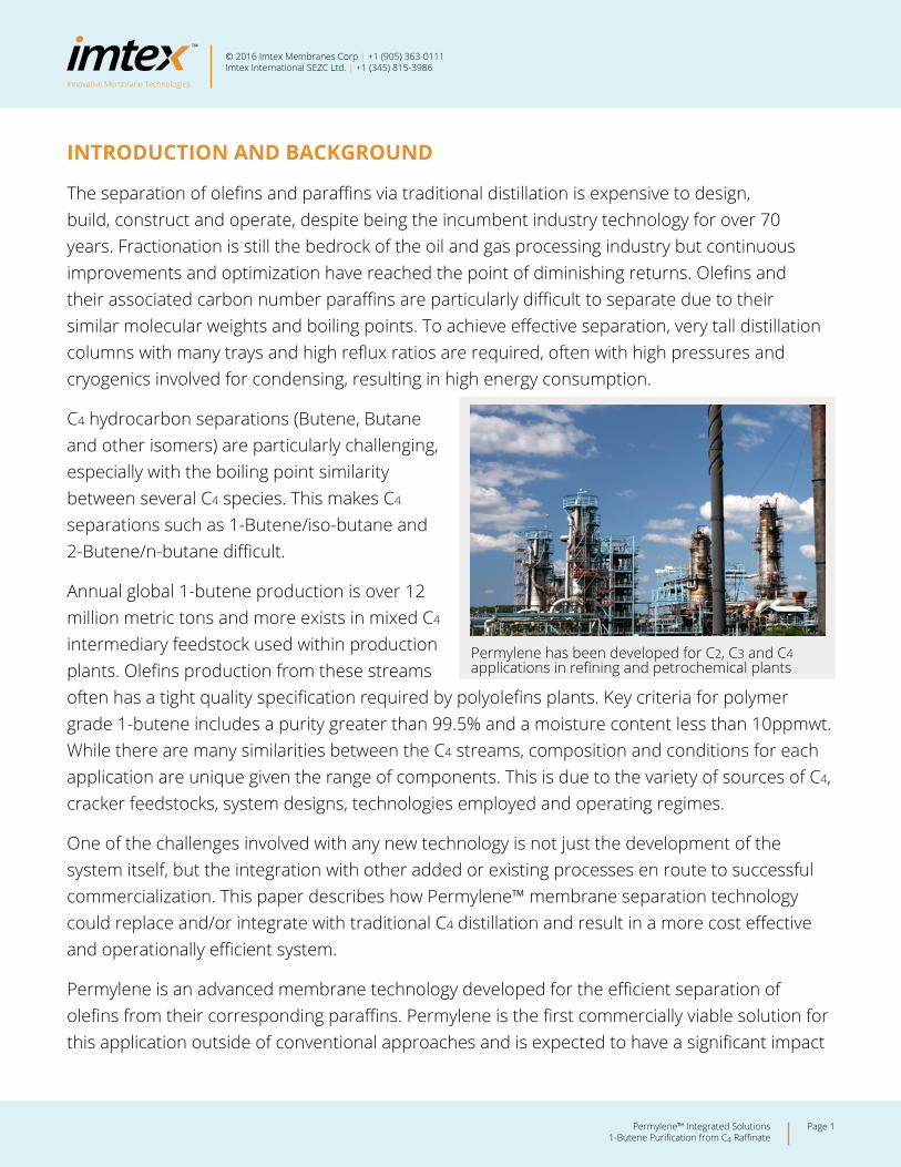
Annual global 1-butene production is over 12 million metric tons and more exists in mixed C4 intermediary feedstock used within production plants. Olefins production from these streams often has a tight quality specification required by polyolefins plants. Key criteria for polymer grade 1-butene includes a purity greater than 99.5% and a moisture content less than 10ppmwt. While there are many similarities between the C4 streams, composition and conditions for each application are unique given the range of components. This is due to the variety of sources of C4, cracker feedstocks, system designs, technologies employed and operating regimes.
One of the challenges involved with any new technology is not just the development of the system itself, but the integration with other added or existing processes en route to successful commercialization. This paper describes how Permylene™ membrane separation technology could replace and/or integrate with traditional C4 distillation and result in a more cost effective and operationally efficient system.
Permylene is an advanced membrane technology developed for the efficient separation of olefins from their corresponding paraffins. Permylene is the first commercially viable solution for this application outside of conventional approaches and is expected to have a significant impact
Permylene has been developed for C2, C3 and C4 applications in refining and petrochemical plants
Innovative Membrane Technologies
Page 2Permylene™ Integrated Solutions 1-Butene Purification from C4 Raffinate
© 2016 Imtex Membranes Corp | +1 (905) 363-0111Imtex International SEZC Ltd. | +1 (345) 815-3986
on the industry, reducing both required upfront capital and ongoing operational costs. Based on a patented facilitated transport mechanism and supporting process, Permylene has been developed for C2, C3 and C4 applications in refining and petrochemical plants.
THE CONVENTIONAL APPROACH TO BUTENE PRODUCTION
The conventional C4 separation case involves a stream with a mixture of paraffinic and olefinic isomers. Often these are generated from other processes and some of these streams are more typically known as Raffinate I or Raffinate II. These streams are valuable as the individual C4 components can be used for a variety of further downstream value-added processes such as alkylation feed, polymer feedstock, metathesis and numerous specialty chemicals. Despite the cost and difficulty in separating these components, there is often a very good business case for doing so, and is often necessary for maximizing feedstock utilization through process integration
Case Study Details
In this example we consider a 120,000 metric tons/year Raffinate II stream with the following composition:
The primary focus for this example will be on the extraction and purification of the 1-Butene component from the other C4 components. There is 68,040 metric tons/year of 1-Butene available in this stream. As C4s have a normal boiling point range of -11.7 to 3.7 °C (for the various isomers), cryogenic conditions are not required to reach a liquid phase necessary for distillation. However, the similarity of the molecules means that separation is still challenging, especially in order to achieve commercially attractive recovery at the required purity specification. The typical recovery performance for these distillation systems is greater than 95%.
Raffinate II Component Type Mol%1-Butene Olefin 56.70Cis-2-Butene Olefin 12.20Trans-2-Butene Olefin 18.30Iso-Butane Paraffin 2.00Normal Butane Paraffin 10.80
TABLE 1Raffinate II stream composition used for this example
Innovative Membrane Technologies
Page 3Permylene™ Integrated Solutions 1-Butene Purification from C4 Raffinate
© 2016 Imtex Membranes Corp | +1 (905) 363-0111Imtex International SEZC Ltd. | +1 (345) 815-3986
Distillation Process System Design
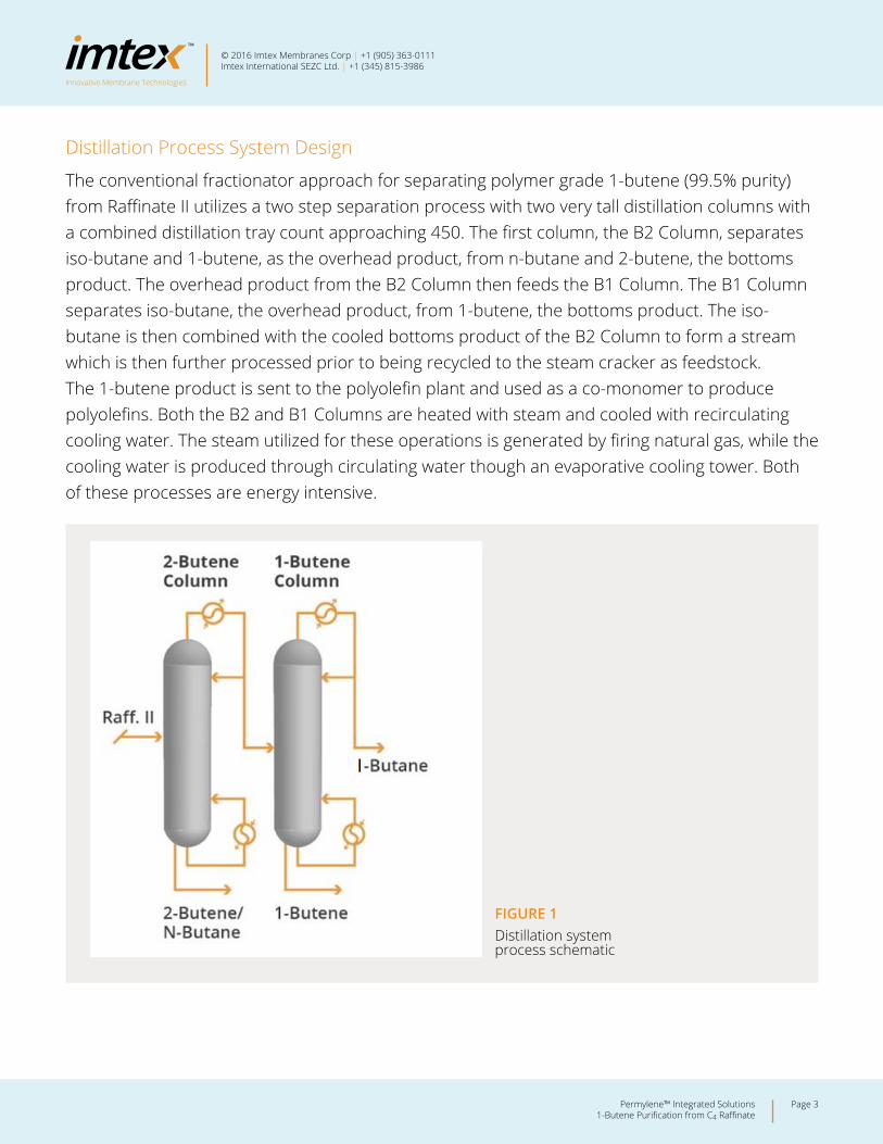
The conventional fractionator approach for separating polymer grade 1-butene (99.5% purity) from Raffinate II utilizes a two step separation process with two very tall distillation columns with a combined distillation tray count approaching 450. The first column, the B2 Column, separates iso-butane and 1-butene, as the overhead product, from n-butane and 2-butene, the bottoms product. The overhead product from the B2 Column then feeds the B1 Column. The B1 Column separates iso-butane, the overhead product, from 1-butene, the bottoms product. The iso-butane is then combined with the cooled bottoms product of the B2 Column to form a stream which is then further processed prior to being recycled to the steam cracker as feedstock. The 1-butene product is sent to the polyolefin plant and used as a co-monomer to produce polyolefins. Both the B2 and B1 Columns are heated with steam and cooled with recirculating cooling water. The steam utilized for these operations is generated by firing natural gas, while the cooling water is produced through circulating water though an evaporative cooling tower. Both of these processes are energy intensive.
FIGURE 1Distillation system process schematic
Innovative Membrane Technologies
Page 4Permylene™ Integrated Solutions 1-Butene Purification from C4 Raffinate
© 2016 Imtex Membranes Corp | +1 (905) 363-0111Imtex International SEZC Ltd. | +1 (345) 815-3986
The distillation system design typically includes vertical vessels with over 200 trays each and requires high reflux ratios, resulting in columns over 200ft tall with associated processing equipment, pumps and compressors. The installation of these components adds to the cost due to the challenging fabrication, transportation and construction which includes erection of the distillation towers. The total equipment weight in this case would be over 200 tonnes (dry weight).
Capital and Energy Costs for Distillation
The energy requirements for the complete system are estimated to be around 40MW (steam, cooling water and electricity) at a total installed capital cost of around $36MM USD which takes into account the logistics of constructing, shipping and installing these large vessels (see appendix D).
Capital Cost Estimate Breakdown
º B2 column system = $18.5 MM USD
º B1 column system = $17.9 MM USD
Despite the high cost, traded 1-Butene prices vary from $1000 to $1500 per metric ton, so this still makes for an attractive business case. If we use a more conservative estimate of $1000/then the gross annual production revenue in this example would be $68 MM USD (this takes into account the full production value of the olefin). The business case in this situation needs to account for the product transfer price, capital and operating cost savings.
The majority of operating costs will derive from fixed costs and energy consumption. Using an approx. energy price of 10c/kWh, the annual energy costs for the combined distillation system would be $32 MM USD.
PERMYLENE TECHNOLOGY – A COST EFFECTIVE ALTERNATIVE
Permylene membrane technology offers a more cost effective integrated solution that achieves the same objective. While there exists a number of process flow and integration options to consider, this example focuses on the replacement of the 1-Butene column to separate 1-Butene from Iso-Butane.
Innovative Membrane Technologies
Page 5Permylene™ Integrated Solutions 1-Butene Purification from C4 Raffinate
© 2016 Imtex Membranes Corp | +1 (905) 363-0111Imtex International SEZC Ltd. | +1 (345) 815-3986
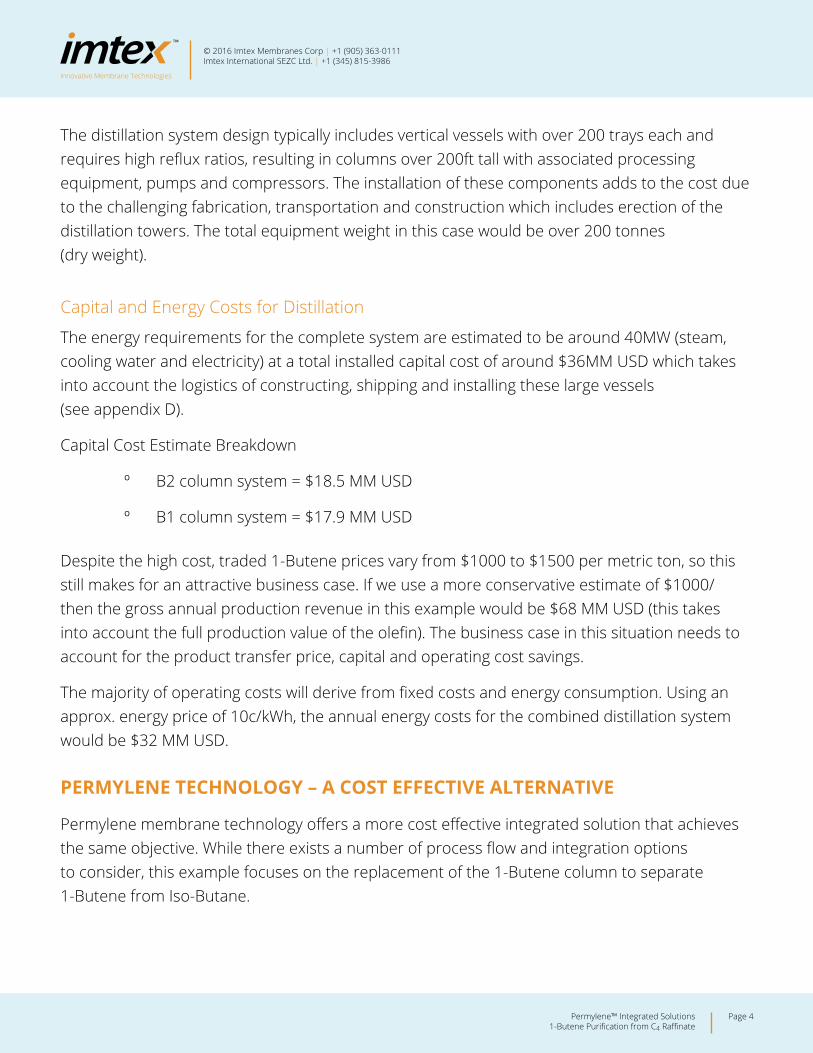
As Permylene’s primary focus is on the separation of olefins and paraffins (all olefin isomers will permeate to a degree) it is still necessary to separate the olefin isomers in the first step. In this example we consider that the Permylene system performs the secondary separation of 1-Butene from iso-butane but it could just as easily perform a first step separation of all olefins from paraffins and a smaller distillation system could be used for the final olefin isomer separation. The most cost effective solution would be dependent on the application and would require a comparative study.
Note that the Permylene system could also be applied to the 2-Butene and N-Butane bottoms stream from the 2-Butene Column to obtain a high purity 2-Butene stream and further enhance feedstock utilization and value.
FIGURE 2Integrated Permylene system process schematic
Innovative Membrane Technologies
Page 6Permylene™ Integrated Solutions 1-Butene Purification from C4 Raffinate
© 2016 Imtex Membranes Corp | +1 (905) 363-0111Imtex International SEZC Ltd. | +1 (345) 815-3986
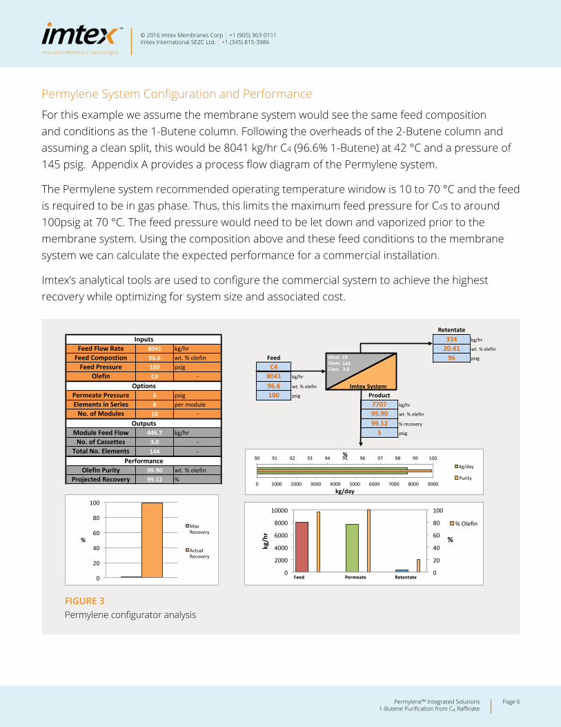
Permylene System Configuration and Performance
For this example we assume the membrane system would see the same feed composition and conditions as the 1-Butene column. Following the overheads of the 2-Butene column and assuming a clean split, this would be 8041 kg/hr C4 (96.6% 1-Butene) at 42 °C and a pressure of 145 psig. Appendix A provides a process flow diagram of the Permylene system.
The Permylene system recommended operating temperature window is 10 to 70 °C and the feed is required to be in gas phase. Thus, this limits the maximum feed pressure for C4s to around 100psig at 70 °C. The feed pressure would need to be let down and vaporized prior to the membrane system. Using the composition above and these feed conditions to the membrane system we can calculate the expected performance for a commercial installation.
Imtex’s analytical tools are used to configure the commercial system to achieve the highest recovery while optimizing for system size and associated cost.
PermyleneTM Configurator
(4) C4 Butene example configurator adjusted.xlsm
Retentate334 kg/hr
8041 20.41 wt. % olefin
96.6 Feed 96 psig
100 C4C4 8041 kg/hr
96.6 wt. % olefin
5 100 psig Product8 per module 7707 kg/hr
18 99.90 wt. % olefin
99.12 % recovery
446.7 kg/hr 5 psig
3.0144
99.9099.12
Module Feed FlowOutputs
-‐No. of Modules
InputsFeed Flow Rate kg/hrFeed Compostion wt. % olefin
Permeate Pressure psigElements in Series
Feed Pressure psigOlefin -‐
Options
Projected Recovery %
No. of Cassettes -‐Total No. Elements -‐
PerformanceOlefin Purity wt. % olefin
Imtex System
18 Mod: Elem: Cass:
144
0
20
40
60
80
100
%
Max Recovery
Actual Recovery
0
2000
4000
6000
8000
10000
Feed Permeate Retentate 0
20
40
60
80
100
kg/hr
%
% Olefin
90 91 92 93 94 95 96 97 98 99 100
0 1000 2000 3000 4000 5000 6000 7000 8000 9000
%
kg/day
kg/day
Purity
3.0
FIGURE 3Permylene configurator analysis
Innovative Membrane Technologies
Page 7Permylene™ Integrated Solutions 1-Butene Purification from C4 Raffinate
© 2016 Imtex Membranes Corp | +1 (905) 363-0111Imtex International SEZC Ltd. | +1 (345) 815-3986
The Imtex configuration analysis is based on both empirical data and theoretical knowledge which is continuously being refined. This analysis suggests that a system of 3 cassettes (each cassette contains 6 modules with 10 membrane elements per module) would be sufficient to achieve 99.1% recovery at a purity of 99.9%. There is a good degree of optimization that can occur for specific targets, such as permeate and retentate stream olefin content or required downstream pressures.
Process Design and Integration
Further to the technology configuration analysis, it is clearly important to determine how the technology would integrate into the plant process design. For this example we assumed that the product would need to be supplied at the same conditions as that from the 1-Butene tower in the original example and achieve the 1-Butene product specification. The distillation system provided the polymer grade 1-butene specification in liquid phase at 175 psig. In order to achieve this, there are a number of supporting items of equipment that will be required such as feed vaporizers, condensers, compressors and driers (as the permeate and retentate streams leave the membrane system humid due to the continuous membrane hydration system that is a critical operational attribute of the Permylene membrane system).
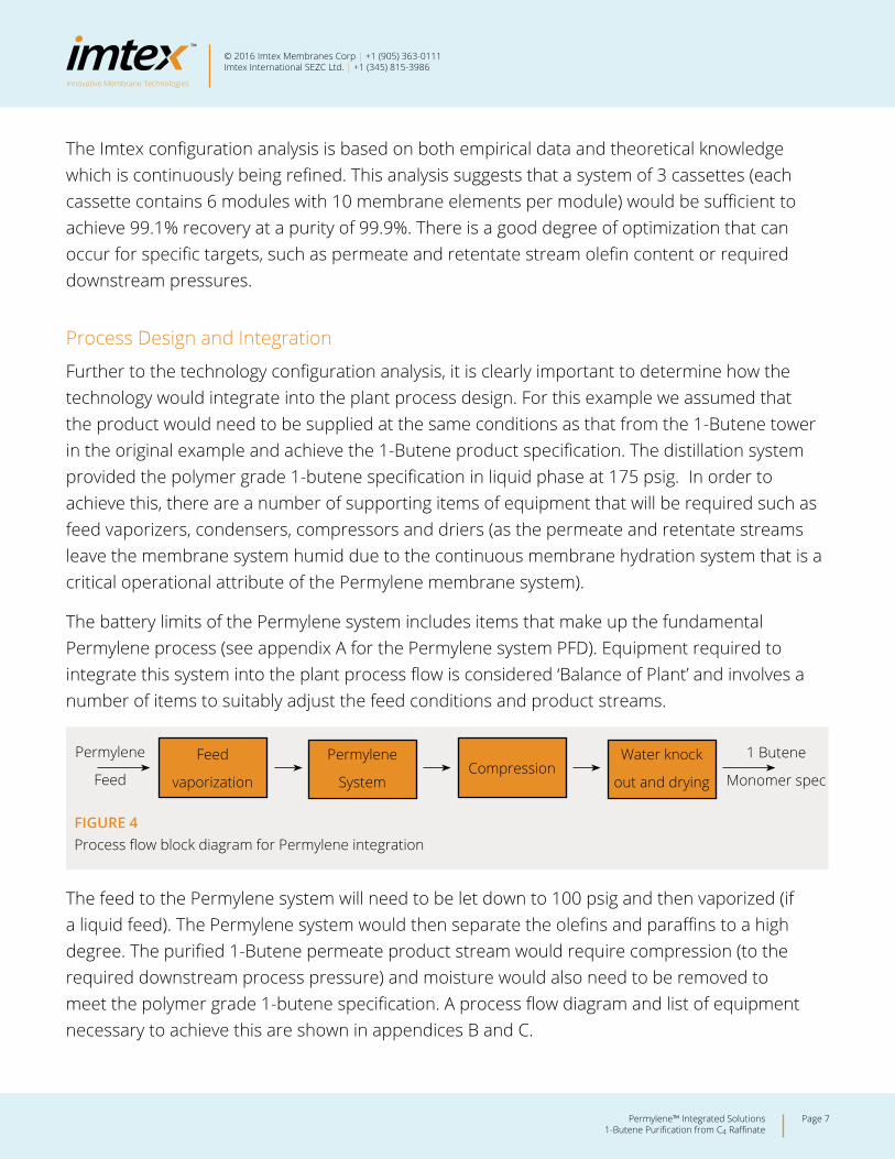
The battery limits of the Permylene system includes items that make up the fundamental Permylene process (see appendix A for the Permylene system PFD). Equipment required to integrate this system into the plant process flow is considered ‘Balance of Plant’ and involves a number of items to suitably adjust the feed conditions and product streams.
The feed to the Permylene system will need to be let down to 100 psig and then vaporized (if a liquid feed). The Permylene system would then separate the olefins and paraffins to a high degree. The purified 1-Butene permeate product stream would require compression (to the required downstream process pressure) and moisture would also need to be removed to meet the polymer grade 1-butene specification. A process flow diagram and list of equipment necessary to achieve this are shown in appendices B and C.
Feed
vaporization
Water knock
out and dryingCompression
Permylene
System
1 Butene
Monomer spec
Permylene
Feed
FIGURE 4Process flow block diagram for Permylene integration
Innovative Membrane Technologies
Page 8Permylene™ Integrated Solutions 1-Butene Purification from C4 Raffinate
© 2016 Imtex Membranes Corp | +1 (905) 363-0111Imtex International SEZC Ltd. | +1 (345) 815-3986
Permylene System Costs and Project Economics
For the business case we need to estimate the total installed cost for the integrated system and operational costs. For a feasibility stage study it is reasonable to adopt a factored approach to some of the cost elements. Using the equipment costs, a Total Installed Cost (TIC) factor has been used to determine the total project cost consistent with a class 5 estimate. These factors vary between estimators, but a factor of 4 for more complex, traditional process equipment and 2-3 for more basic items seems reasonable.
On that basis the total installed cost for the Permylene integrated system (including balance of plant) is estimated to be $6.9 MM USD (see appendix D) which is less than half the cost of the B1 distillation system ($17.9 MM USD for comparison), a capital cost savings of over $10 MM USD. This integrated 1-butene purification solution, including the B2 column, reduces the capital cost of a 1-Butene purification system significantly, from an estimated $36.4 MM down to $25.4 MM USD.
The operational costs are predominantly focused on the energy requirements for both the Permylene membrane system and balance of plant which amounts to 315 kW. Compared to around 20MW needed for the B1 distillation system, this is a functional reduction of over 95%. The complete integrated system total power requirements (for a Permylene system and the B2 column) would be just over 20MW, compared to the conventional system power requirement of 40MW. So the fully integrated system’s energy requirements are nearly half that of the conventional distillation case. This equates to a saving of nearly $16MM USD/yr in operational costs.
The 1-Butene recovery from the Permylene system is over 99%. For the purpose of comparison, if we assume recovery parity and the same fixed operating costs then a conservative business case can be based on both the capital and operational savings alone. Using a discount rate of 15% this would equate to Net Present Value of over $75 MM USD over ten years.
Further to this direct cost saving there is an additional opportunity to enhance feedstock utilization through the separation, recovery and purification of the 2-Butene from the bottoms of the B2 column, which is useful for a number of applications including metathesis. Assuming that this stream would otherwise be hydrogenated and recycled to the cracker, this would also reduce the capital cost required to utilize this stream.
Innovative Membrane Technologies
Page 9Permylene™ Integrated Solutions 1-Butene Purification from C4 Raffinate
© 2016 Imtex Membranes Corp | +1 (905) 363-0111Imtex International SEZC Ltd. | +1 (345) 815-3986
Other C4 Applications and Olefin Concentrations
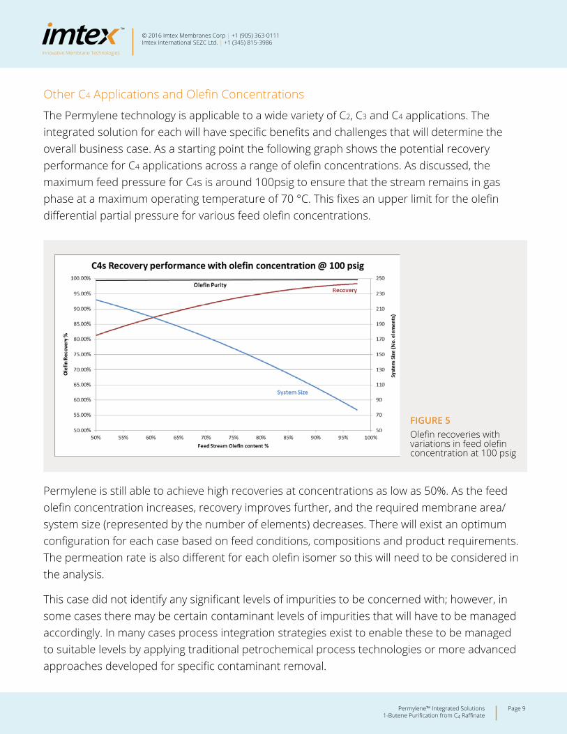
The Permylene technology is applicable to a wide variety of C2, C3 and C4 applications. The integrated solution for each will have specific benefits and challenges that will determine the overall business case. As a starting point the following graph shows the potential recovery performance for C4 applications across a range of olefin concentrations. As discussed, the maximum feed pressure for C4s is around 100psig to ensure that the stream remains in gas phase at a maximum operating temperature of 70 °C. This fixes an upper limit for the olefin differential partial pressure for various feed olefin concentrations.
Permylene is still able to achieve high recoveries at concentrations as low as 50%. As the feed olefin concentration increases, recovery improves further, and the required membrane area/system size (represented by the number of elements) decreases. There will exist an optimum configuration for each case based on feed conditions, compositions and product requirements. The permeation rate is also different for each olefin isomer so this will need to be considered in the analysis.
This case did not identify any significant levels of impurities to be concerned with; however, in some cases there may be certain contaminant levels of impurities that will have to be managed accordingly. In many cases process integration strategies exist to enable these to be managed to suitable levels by applying traditional petrochemical process technologies or more advanced approaches developed for specific contaminant removal.
FIGURE 5Olefin recoveries with variations in feed olefin concentration at 100 psig
Innovative Membrane Technologies
Page 10Permylene™ Integrated Solutions 1-Butene Purification from C4 Raffinate
© 2016 Imtex Membranes Corp | +1 (905) 363-0111Imtex International SEZC Ltd. | +1 (345) 815-3986
SUMMARY
Both the potential upfront capital and operational cost savings of a Permylene membrane system are significant, being greater than 50% and 90% respectively, compared to the functional conventional distillation equivalent. This is a good example of how Permylene could replace or work in a hybrid mode with distillation. As well as the operational cost savings from reducing energy consumption, a Permylene solution will also result in significant environmental benefits due to lower CO2, NOx and heat emissions associated with heat generation, management and power consumption. The Permylene technology should be considered for new production facilities, enhancing existing facilities, de-bottlenecking and replacing end of life systems. In addition there will also exist opportunities for new products where olefin extraction via distillation has proven to be impractical or uneconomical.
This case study is just one example that quantifies the potential benefits that Permylene membrane technology can bring to the industry. There are a wide variety of potential applications across C2, C3 and C4 olefins processes that could benefit.
In an increasingly competitive market, strategies focusing on value enhancing technologies, cost savings and emissions reductions are becoming more prevalent. Imtex Membranes is working with several high profile industrial clients to further explore the technical space for Permylene technology and identify applications with strong business cases on which to base demonstration activities. Imtex has reviewed a range of C4 applications in this regard for a variety of clients and applications.
One of the challenges with C4 applications is the wide variety of feed concentrations and compositions which will make each and every application unique to some degree. That said, there are also similarities, and many of the benefits presented here will also be applicable to many other cases. Please contact us to discuss your specific case at your facility.
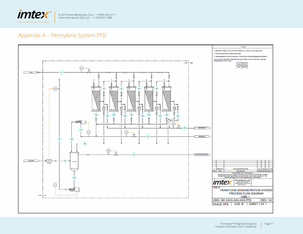
Appendix A – Permylene System PFD
Innovative Membrane Technologies
Page 11Permylene™ Integrated Solutions 1-Butene Purification from C4 Raffinate
© 2016 Imtex Membranes Corp | +1 (905) 363-0111Imtex International SEZC Ltd. | +1 (345) 815-3986
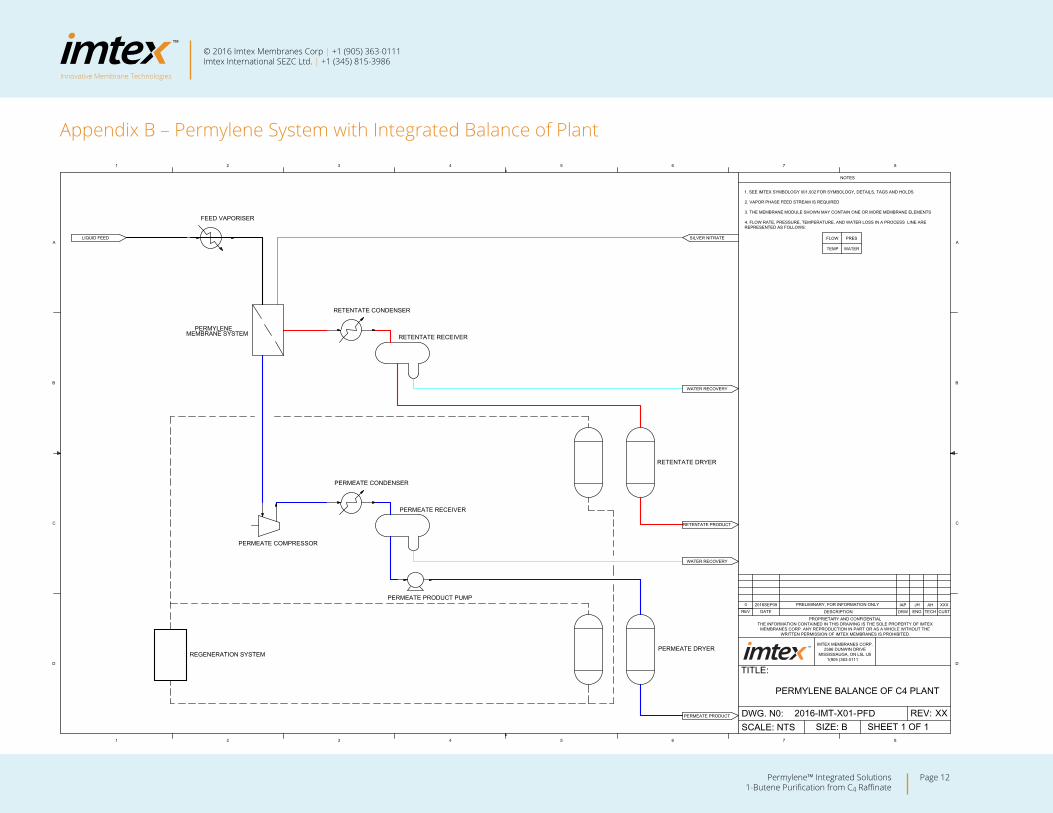
Appendix B – Permylene System with Integrated Balance of Plant
LIQUID FEED
WATER RECOVERY
WATER RECOVERY
RETENTATE PRODUCT
PERMEATE PRODUCT
SILVER NITRATE
FEED VAPORISER
RETENTATE CONDENSER
PERMEATE CONDENSER
PERMEATE COMPRESSOR
REGENERATION SYSTEMPERMEATE DRYER
RETENTATE DRYER
PERMEATE PRODUCT PUMP
PERMEATE RECEIVER
RETENTATE RECEIVERPERMYLENE
MEMBRANE SYSTEM
SCALE: NTS SIZE: B SHEET REV: 2016-IMT-X01-
TITLE:
PROPRIETARY AND CONFIDENTIALTHE INFORMATION CONTAINED IN THIS DRAWING IS THE SOLE PROPERTY OF IMTEX
MEMBRANES CORP. ANY REPRODUCTION IN PART OR AS A WHOLE WITHOUT THE WRITTEN PERMISSION OF IMTEX MEMBRANES IS PROHIBITED.
ENG TECH CUSTREV DATE DESCRIPTION DRW
NOTES
87654321
87654321
D
C
B
A
D
C
B
A
IMTEX MEMBRANES CORP.2596 DUNWIN DRIVE
MISSISSAUGA, ON L5L IJ51(905 )363-0111
DWG. N0: XX1 OF 1
JH AH XXX0 2016SEP09 IAP
PFD
1. SEE IMTEX SYMBOLOGY 001,002 FOR SYMBOLOGY, DETAILS, TAGS AND HOLDS
2. VAPOR PHASE FEED STREAM IS REQUIRED
3. THE MEMBRANE MODULE SHOWN MAY CONTAIN ONE OR MORE MEMBRANE ELEMENTS
4. FLOW RATE, PRESSURE, TEMPERATURE, AND WATER LOSS IN A PROCESS LINE ARE REPRESENTED AS FOLLOWS:
TEMP WATER
PRES FLOW
PRELIMINARY, FOR INFORMATION ONLY
PERMYLENE BALANCE OF C4 PLANT
Innovative Membrane Technologies
Page 12Permylene™ Integrated Solutions 1-Butene Purification from C4 Raffinate
© 2016 Imtex Membranes Corp | +1 (905) 363-0111Imtex International SEZC Ltd. | +1 (345) 815-3986
Innovative Membrane Technologies
Page 13Permylene™ Integrated Solutions 1-Butene Purification from C4 Raffinate
© 2016 Imtex Membranes Corp | +1 (905) 363-0111Imtex International SEZC Ltd. | +1 (345) 815-3986
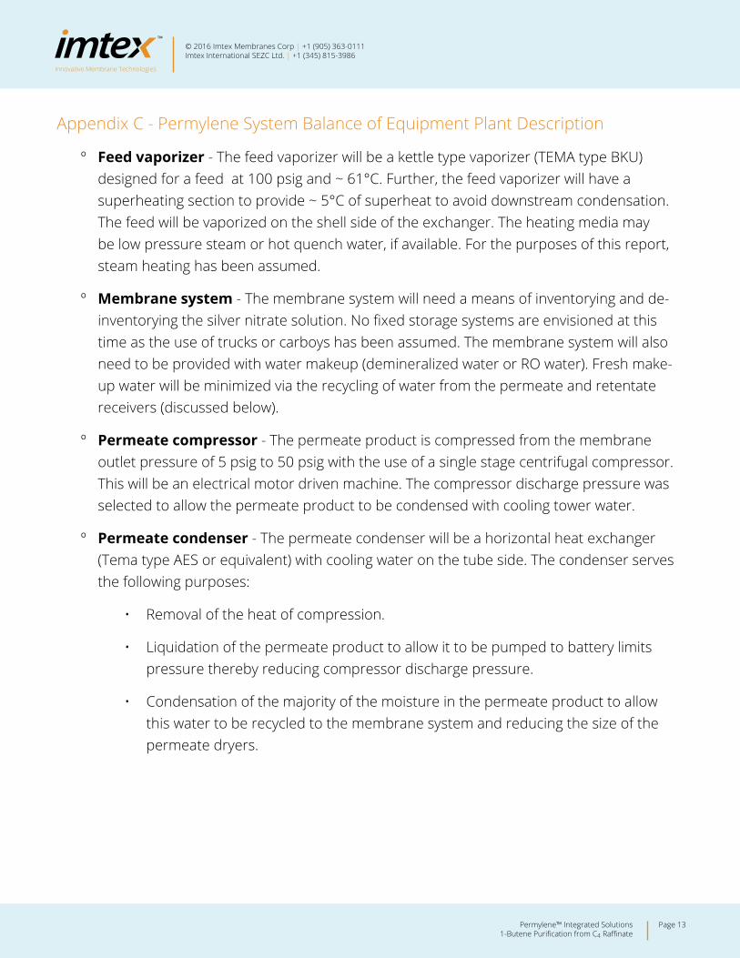
Appendix C - Permylene System Balance of Equipment Plant Description
º Feed vaporizer - The feed vaporizer will be a kettle type vaporizer (TEMA type BKU) designed for a feed at 100 psig and ~ 61°C. Further, the feed vaporizer will have a superheating section to provide ~ 5°C of superheat to avoid downstream condensation. The feed will be vaporized on the shell side of the exchanger. The heating media may be low pressure steam or hot quench water, if available. For the purposes of this report, steam heating has been assumed.
º Membrane system - The membrane system will need a means of inventorying and de-inventorying the silver nitrate solution. No fixed storage systems are envisioned at this time as the use of trucks or carboys has been assumed. The membrane system will also need to be provided with water makeup (demineralized water or RO water). Fresh make-up water will be minimized via the recycling of water from the permeate and retentate receivers (discussed below).
º Permeate compressor - The permeate product is compressed from the membrane outlet pressure of 5 psig to 50 psig with the use of a single stage centrifugal compressor. This will be an electrical motor driven machine. The compressor discharge pressure was selected to allow the permeate product to be condensed with cooling tower water.
º Permeate condenser - The permeate condenser will be a horizontal heat exchanger (Tema type AES or equivalent) with cooling water on the tube side. The condenser serves the following purposes:
• Removal of the heat of compression.
• Liquidation of the permeate product to allow it to be pumped to battery limits pressure thereby reducing compressor discharge pressure.
• Condensation of the majority of the moisture in the permeate product to allow this water to be recycled to the membrane system and reducing the size of the permeate dryers.
Innovative Membrane Technologies
Page 14Permylene™ Integrated Solutions 1-Butene Purification from C4 Raffinate
© 2016 Imtex Membranes Corp | +1 (905) 363-0111Imtex International SEZC Ltd. | +1 (345) 815-3986
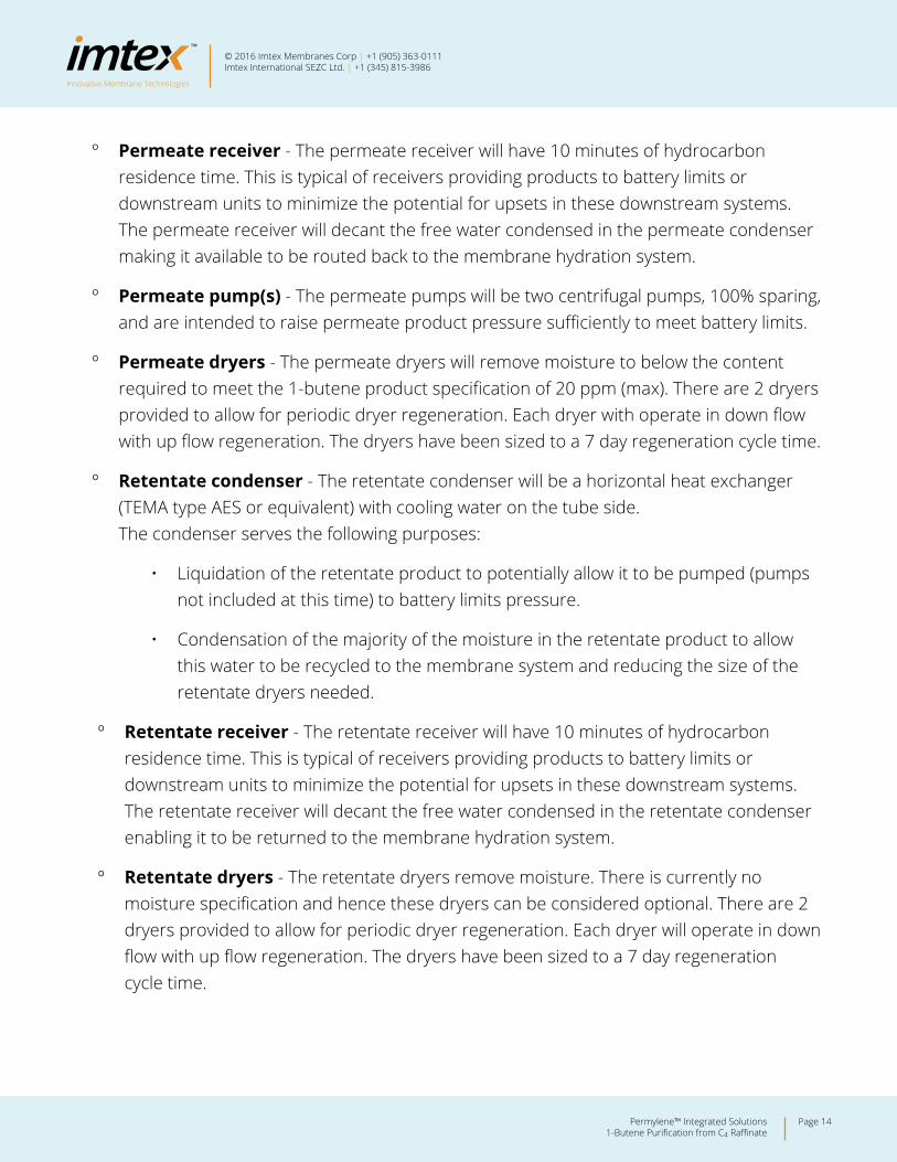
º Permeate receiver - The permeate receiver will have 10 minutes of hydrocarbon residence time. This is typical of receivers providing products to battery limits or downstream units to minimize the potential for upsets in these downstream systems. The permeate receiver will decant the free water condensed in the permeate condenser making it available to be routed back to the membrane hydration system.
º Permeate pump(s) - The permeate pumps will be two centrifugal pumps, 100% sparing, and are intended to raise permeate product pressure sufficiently to meet battery limits.
º Permeate dryers - The permeate dryers will remove moisture to below the content required to meet the 1-butene product specification of 20 ppm (max). There are 2 dryers provided to allow for periodic dryer regeneration. Each dryer with operate in down flow with up flow regeneration. The dryers have been sized to a 7 day regeneration cycle time.
º Retentate condenser - The retentate condenser will be a horizontal heat exchanger (TEMA type AES or equivalent) with cooling water on the tube side. The condenser serves the following purposes:
• Liquidation of the retentate product to potentially allow it to be pumped (pumps not included at this time) to battery limits pressure.
• Condensation of the majority of the moisture in the retentate product to allow this water to be recycled to the membrane system and reducing the size of the retentate dryers needed.
º Retentate receiver - The retentate receiver will have 10 minutes of hydrocarbon residence time. This is typical of receivers providing products to battery limits or downstream units to minimize the potential for upsets in these downstream systems. The retentate receiver will decant the free water condensed in the retentate condenser enabling it to be returned to the membrane hydration system.
º Retentate dryers - The retentate dryers remove moisture. There is currently no moisture specification and hence these dryers can be considered optional. There are 2 dryers provided to allow for periodic dryer regeneration. Each dryer will operate in down flow with up flow regeneration. The dryers have been sized to a 7 day regeneration cycle time.
Innovative Membrane Technologies
Page 15Permylene™ Integrated Solutions 1-Butene Purification from C4 Raffinate
© 2016 Imtex Membranes Corp | +1 (905) 363-0111Imtex International SEZC Ltd. | +1 (345) 815-3986
º Dryer regeneration system - Olefins plants have dryer/reactor regeneration systems. These systems use fuel gas, primarily methane, that has been dried to a water dew point of less than -100°C. The fuel gas comes from the cryogenic separation section and is diverted as needed to the regeneration system which is composed of a heater, cooler/condenser and water decanter. Fuel gas from this system then flows to the plant’s fuel gas systems.
• For plants where this system is not available to regenerate dryers in the membrane unit, an independent system will be required. This system is similar to the olefins plant system with the exception that it would use nitrogen as the regeneration gas media and require the addition of a blower to recirculate the regeneration gas. For the purposes of the equipment cost estimate, it has been assumed at this time that the central olefins plant regeneration system can be utilized for the membrane system.
Innovative Membrane Technologies
Page 16Permylene™ Integrated Solutions 1-Butene Purification from C4 Raffinate
© 2016 Imtex Membranes Corp | +1 (905) 363-0111Imtex International SEZC Ltd. | +1 (345) 815-3986
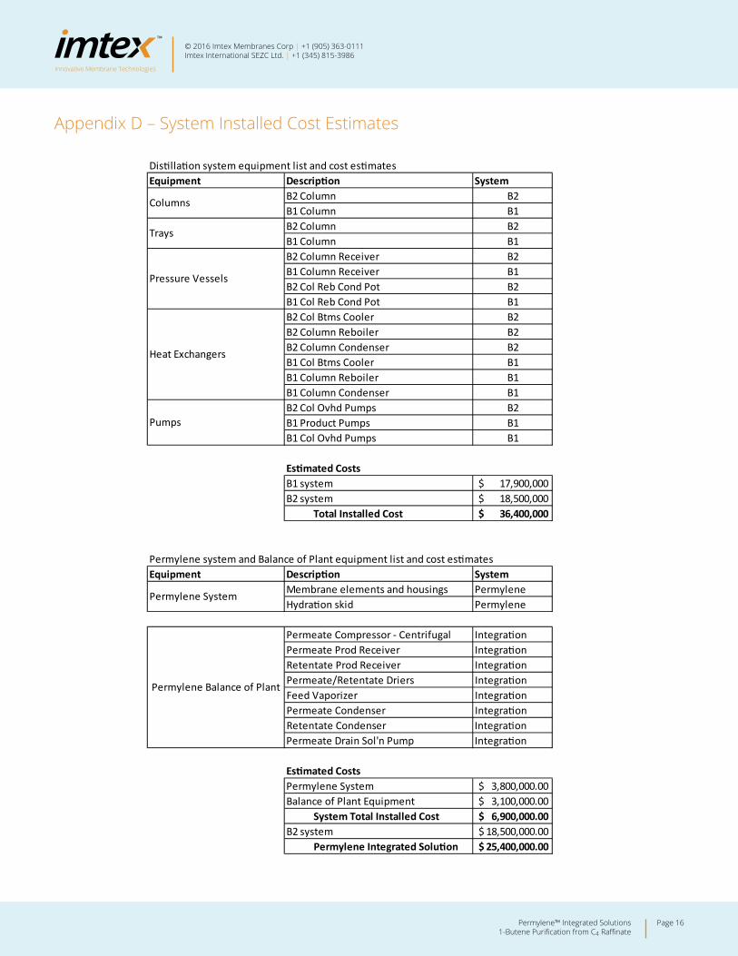
Appendix D – System Installed Cost Estimates
Distillation system equipment list and cost estimatesEquipment Description System
B2 Column B2B1 Column B1B2 Column B2B1 Column B1B2 Column Receiver B2B1 Column Receiver B1B2 Col Reb Cond Pot B2B1 Col Reb Cond Pot B1B2 Col Btms Cooler B2B2 Column Reboiler B2B2 Column Condenser B2B1 Col Btms Cooler B1B1 Column Reboiler B1B1 Column Condenser B1B2 Col Ovhd Pumps B2B1 Product Pumps B1B1 Col Ovhd Pumps B1
Estimated CostsB1 system 17,900,000$ B2 system 18,500,000$
Total Installed Cost 36,400,000$
Permylene system and Balance of Plant equipment list and cost estimatesEquipment Description System
Membrane elements and housings PermyleneHydration skid Permylene
Permeate Compressor - Centrifugal IntegrationPermeate Prod Receiver IntegrationRetentate Prod Receiver IntegrationPermeate/Retentate Driers IntegrationFeed Vaporizer IntegrationPermeate Condenser IntegrationRetentate Condenser IntegrationPermeate Drain Sol'n Pump Integration
Estimated CostsPermylene System 3,800,000.00$ Balance of Plant Equipment 3,100,000.00$
System Total Installed Cost 6,900,000.00$ B2 system 18,500,000.00$
Permylene Integrated Solution 25,400,000.00$
Permylene Balance of Plant
Columns
Trays
Pressure Vessels
Heat Exchangers
Pumps
Permylene System
© 2016 Imtex Membranes Corp | +1 (905) 363-0111Imtex International SEZC Ltd. | +1 (345) 815-3986
CONTACTS
Addresses
Imtex Membranes Corp. Headquarters 2596 Dunwin Drive Mississauga, ON L5L 1J5 [email protected] Tel: + 1 (905) 363-0111
North America Business DevelopmentDale Kline [email protected] Tel: + 1 (803) 554-1002
International Business Development Jamie [email protected]: + 1 (345) 815-3986
Web
www.imtexmembranes.com Go online to access whitepapers, gain a better understanding of our technology and discover more interactive content.
Social
imtex-membranes
@ImtexMembranes
+Imtexmembranescom
ImtexMembranes