Embed Size (px)
Citation preview
1
Building Information Management & Modeling
(BIMM)
2
Problem Statement & Objective
• Problem Statement: NAVFAC lacks a comprehensive strategy for collecting, managing, & sharing required data & information through the lifecycle of a facility from planning to disposal
• Objective: Provide accurate, current, accessible facility data to improve management across BLs/SLs, and reduce total ownership cost for our customers (internal and external)
3
BIM Goal
• NAVFAC BIM will….1. Identify inefficiencies, data redundancy, &
gaps in current process2. Integrate the Stove Pipes by linking the
data3. Insure buy-in of integrated processes
across BL/SL4. Improve lines of communication, resulting
in closely coordinated BMS processes 5. Potentially re-align roles & responsibilities6. Optimize current capabilities & determine
future state
4
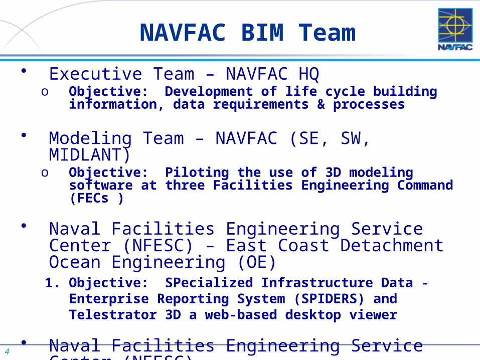
NAVFAC BIM Team
• Executive Team – NAVFAC HQo Objective: Development of life cycle building information,
data requirements & processes
• Modeling Team – NAVFAC (SE, SW, MIDLANT)o Objective: Piloting the use of 3D modeling software at three
Facilities Engineering Command (FECs )
• Naval Facilities Engineering Service Center (NFESC) – East Coast Detachment Ocean Engineering (OE)
1. Objective: SPecialized Infrastructure Data - Enterprise Reporting System (SPIDERS) and Telestrator 3D a web-based desktop viewer
• Naval Facilities Engineering Service Center (NFESC)1. Objective: Planned effort on using BIM to work toward
energy and sustainability goals
5
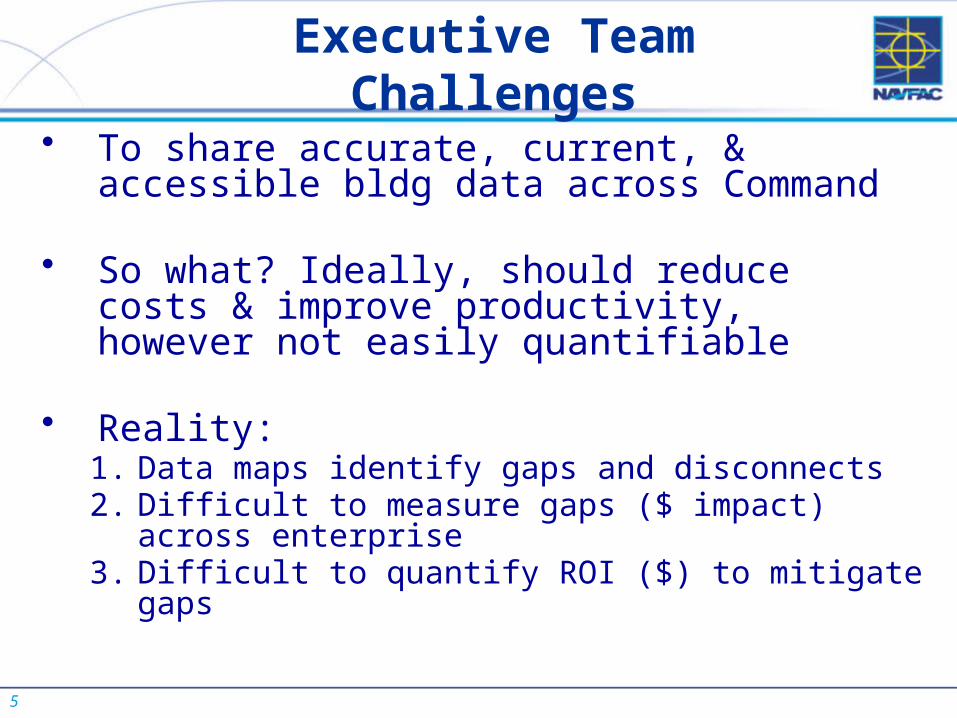
Executive Team Challenges
• To share accurate, current, & accessible bldg data across Command
• So what? Ideally, should reduce costs & improve productivity, however not easily quantifiable
• Reality: 1. Data maps identify gaps and disconnects 2. Difficult to measure gaps ($ impact) across enterprise3. Difficult to quantify ROI ($) to mitigate gaps
6
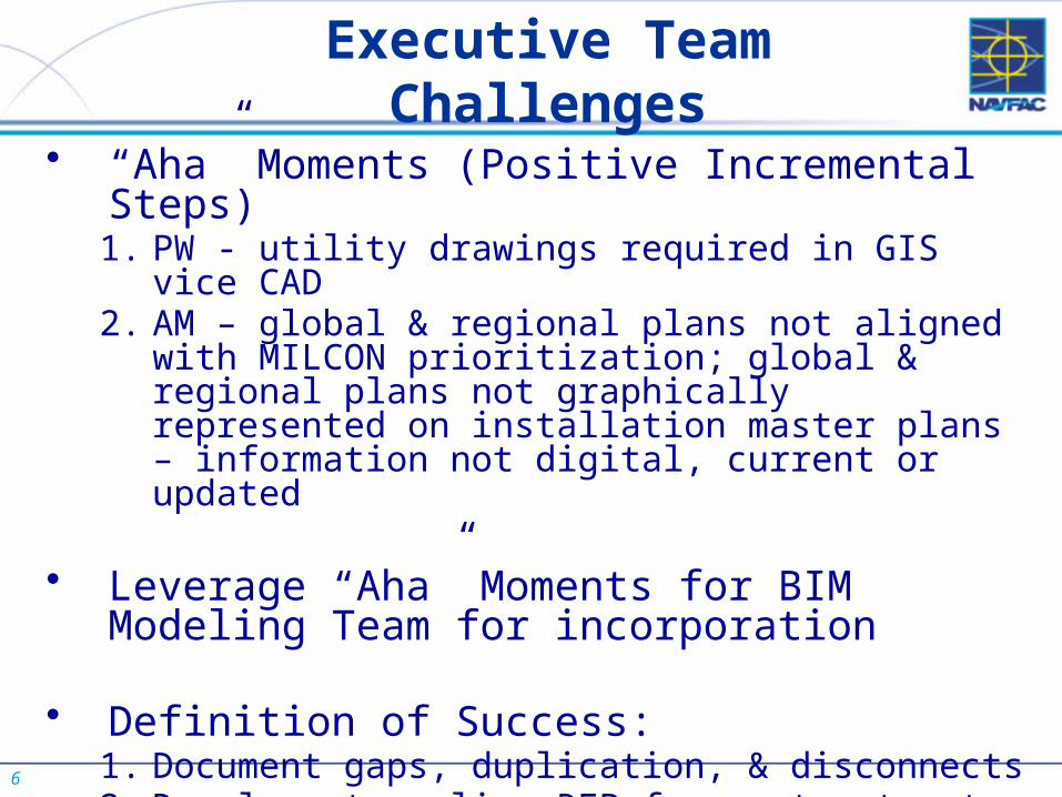
Executive Team Challenges
• “Aha” Moments (Positive Incremental Steps) 1. PW - utility drawings required in GIS vice CAD2. AM – global & regional plans not aligned with MILCON
prioritization; global & regional plans not graphically represented on installation master plans – information not digital, current or updated
• Leverage “Aha” Moments for BIM Modeling Team for incorporation
• Definition of Success: 1. Document gaps, duplication, & disconnects2. Develop streamline RFP for contractor to execute IT
data fixes
7
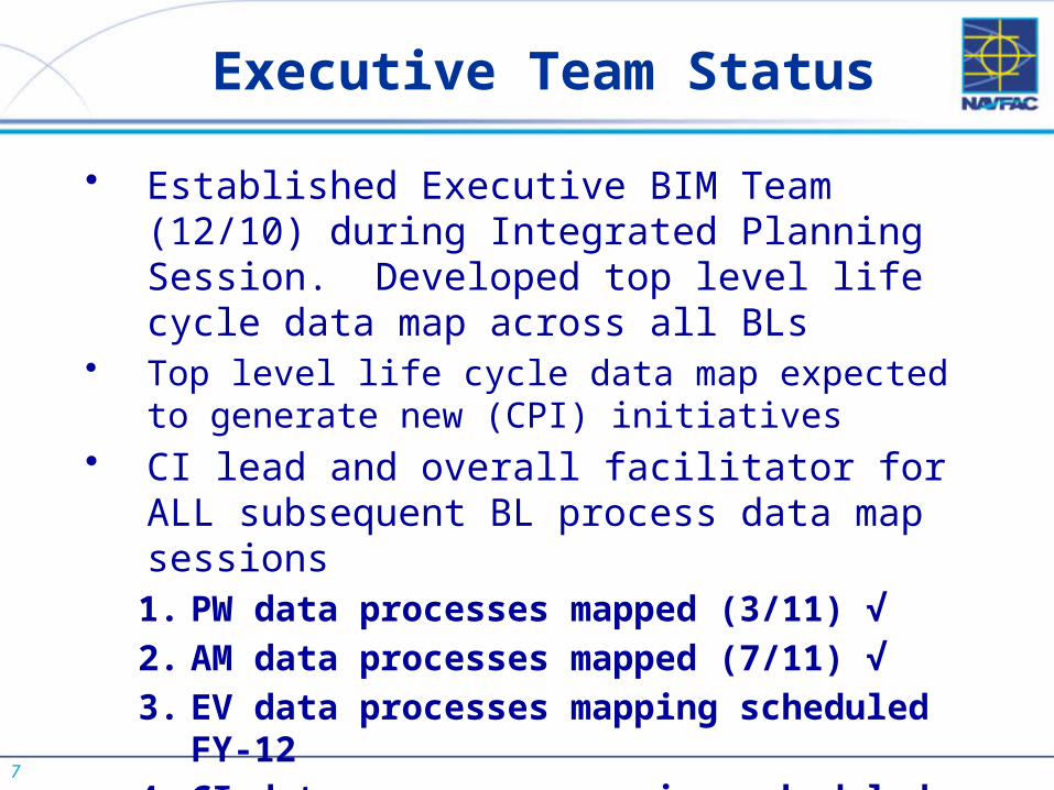
Executive Team Status
• Established Executive BIM Team (12/10) during Integrated Planning Session. Developed top level life cycle data map across all BLs
• Top level life cycle data map expected to generate new (CPI) initiatives
• CI lead and overall facilitator for ALL subsequent BL process data map sessions1. PW data processes mapped (3/11) √
2. AM data processes mapped (7/11) √
3. EV data processes mapping scheduled FY-12
4. CI data processes mapping scheduled FY-12
8
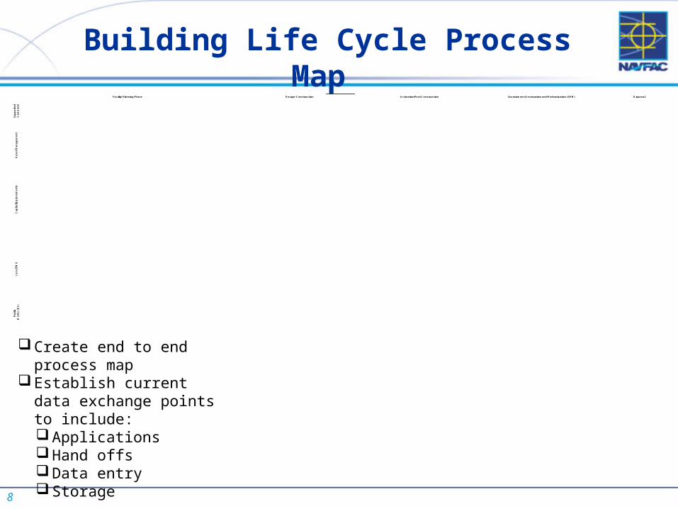
Building Life Cycle Process Map
Create end to end process map
Establish current data exchange points to include: Applications Hand offs Data entry Storage
Su
pp
ort
ed
Co
mm
an
dA
ss
et
Ma
na
ge
me
nt
Ca
pit
al I
mp
rov
em
en
tsL
oc
al P
WD
Pu
blic
Wo
rks
(B
L)
Facility Planning Phase Design-Construction Activation/Post Construction Sustainment, Restoration and Modernization (SRM) Disposal
StartM ission Change
Need Facility
Use / M odify Existing
Facilities or Build New
Evaluate Real Estate
Customer Requirements
Existing Facility DataInstallation/PWD
1391
Preliminary Economic Analysis
Dynamic M aster Planning
Conduct Land Use Capability
CIP Environmental
Constraints Identified
NEPA-CAT/EA/EISM ap Facilities
M ap Environmental ConstraintsM ap Utilities
M ap Infrastructure
Site Approval
Co
mp
lete
Re
gio
n /
FE
C 1
39
1
Develop Design
Award DB Contract or Construction
Contract
Basis of Design RFP (D B)
Budget Ready 1391 10% D esign
Preliminary Design Authorization
Installation/PWD 1391LEED Registration
Final D esign Authorization
Criteria/Regulations
Authority to Advertise
Award DB Contract Final D esign
Award Construction Contract
Construct Facility
Turn Over Facility
Interim BOD 1354
Design Plans & Specs
Authority to Advertise (DBB)
CalculationsPlans & Specs
Total Ownership Cost Schedule of
Prices
eOM SI's
Contractor Facility Data (M AXIM O)
Commissioning Data
As-Builts/Floor Plans
Future:ICS
AccreditationLoaded into
eFilesLEED
Accreditation goes to PW? Review OM SI M anuals
As-Builts (PW)
Training
Commissioning Period
"Activiation"
Warranty Period
Simultaneous Activities
Financial Closeout
(1 yr after BOD)
LEED Accreditation
Final 1354
Place holder:IT Systems
NIRIS SystemEPGEIM S for ComplianceDrCheckseProjectsAnalyze GISPublish CIPLink to inFADS
Preventive M aintenance
Work Order Completion
LEED Issues (Future)
Update to M AXIM O (transfer to inFADS)
CategoryIII/IVGo to Service Call
(Generated)
Category I/II Go to
eProjects
Assign In-House or BOS
Contract
WIS
Final 1354
Load M AXIM O (M anual/Auto)
Work Order/Project
Documents
Updates to Condition
As-Builts Updates
Service Contract
Energy Data
Audits and Inspections
CUBIC
DUERS
CIRCUITS (future)
--ER, UP, UA, M DM
Energy DataSimultaneous Activities:
Asset Evaluation/BFR ValidateRetor-Commission D ataEnvironmental ComplianceLand Use Change Tracker(EV)
Floor Plans (Contractor Site Plans)
D isposal
Demolish
Enhanced Use
Transfer
Sell
Declare Excess
Supp
orte
dCo
mm
and
Asse
t M
anag
emen
tCa
pita
lIm
prov
emen
tsPu
blic
Wor
ksIT
Ap
ps
Facility Planning Phase Design - Construction Activation / Post Construction Sustainment, Restoration, and Modernization (SRM) Disposal
9
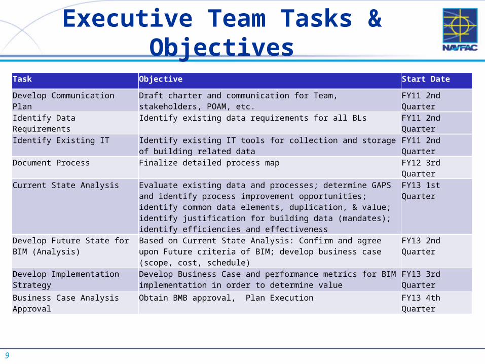
Executive Team Tasks & Objectives
Task Objective Start Date
Develop Communication Plan Draft charter and communication for Team, stakeholders, POAM, etc. FY11 2nd Quarter
Identify Data Requirements Identify existing data requirements for all BLs FY11 2nd Quarter
Identify Existing IT Identify existing IT tools for collection and storage of building related data
FY11 2nd Quarter
Document Process Finalize detailed process map FY12 3rd Quarter
Current State Analysis Evaluate existing data and processes; determine GAPS and identify process improvement opportunities; identify common data elements, duplication, & value; identify justification for building data (mandates); identify efficiencies and effectiveness
FY13 1st Quarter
Develop Future State for BIM (Analysis)
Based on Current State Analysis: Confirm and agree upon Future criteria of BIM; develop business case (scope, cost, schedule)
FY13 2nd Quarter
Develop Implementation Strategy Develop Business Case and performance metrics for BIM implementation in order to determine value
FY13 3rd Quarter
Business Case Analysis Approval Obtain BMB approval, Plan Execution FY13 4th Quarter
10
• MIDLANT BIM Projects: • Renovation of Barracks K-K and K-J at the
Norfolk Naval Station, FY12• Renovation of Barracks I-F at the Norfolk
Naval Station, FY12• SE - BEQ project FY-12 start• SW – MV22 Hangar FY-12 start
Modeling Team Status
11
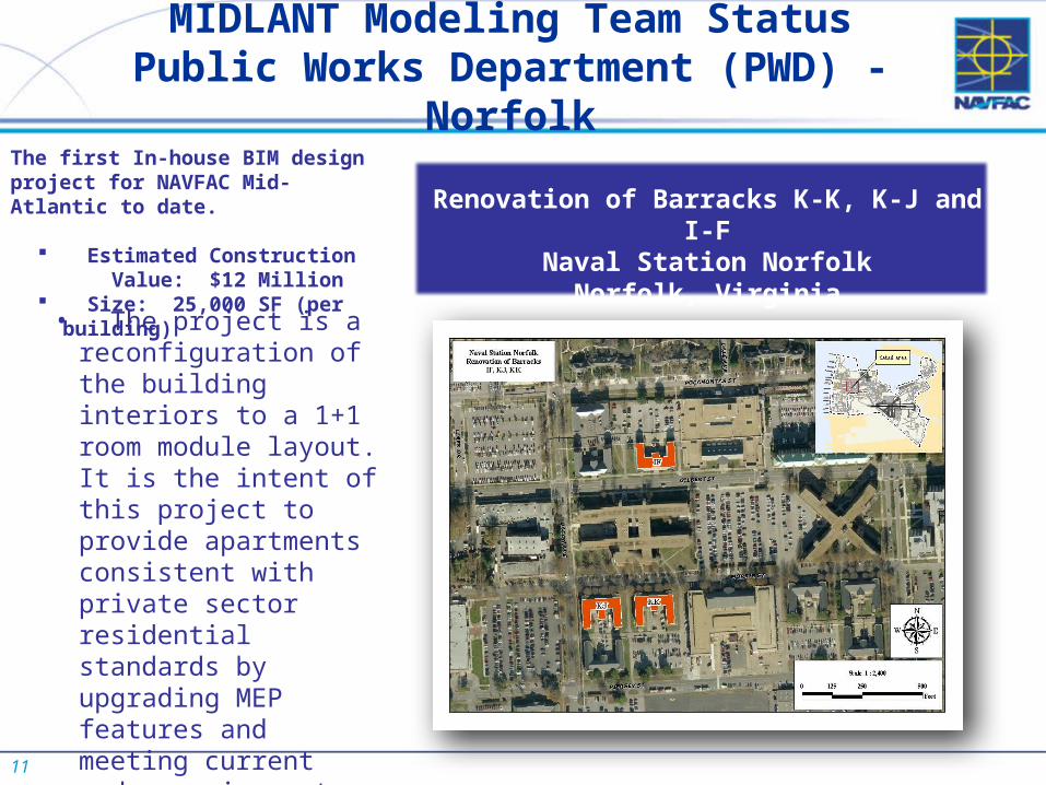
MIDLANT Modeling Team StatusPublic Works Department (PWD) - Norfolk
• The project is a reconfiguration of the building interiors to a 1+1 room module layout. It is the intent of this project to provide apartments consistent with private sector residential standards by upgrading MEP features and meeting current code requirements.
• Pursue LEED Silver Certification
Renovation of Barracks K-K, K-J and I-FNaval Station Norfolk
Norfolk, Virginia
The first In-house BIM design project for NAVFAC Mid-Atlantic to date.
Estimated Construction Value: $12 Million
Size: 25,000 SF (per building)
12
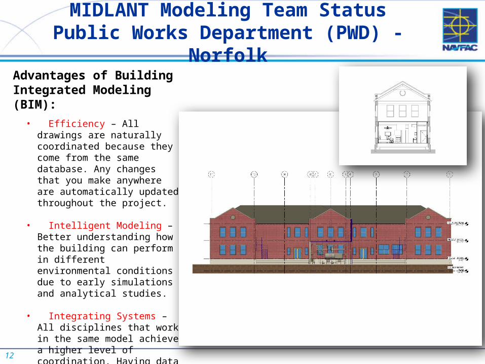
MIDLANT Modeling Team StatusPublic Works Department (PWD) - Norfolk
Advantages of Building Integrated Modeling (BIM):
• Efficiency – All drawings are naturally coordinated because they come from the same database. Any changes that you make anywhere are automatically updated throughout the project.
• Intelligent Modeling – Better understanding how the building can perform in different environmental conditions due to early simulations and analytical studies.
• Integrating Systems – All disciplines that work in the same model achieve a higher level of coordination. Having data and graphics completely integrated make sure that designs are in line with programmatic requirements.
13
NFESC – East Coast Detachment OE BIM Overview
• SPIDERS – Is a data management tool containing normalized waterfront and bridge facility configuration, component, capacity and condition information
• Telestrator 3D is a web-based desktop viewer that can readily interface with SPIDERS1. It currently visualizes geospatially accurate
weapon platforms, installations, facilities and shore interface support equipment
2. It operates on the NMCI Network
14
NFESC – East Coast Detachment OE Schedule
• SPIDERS 1.0 currently in development to support PW – provides asset condition data (and work order information in the future) to MAXIMO; ATO planned for 30 June, 2011
• SPIDERS 2.0 will be connected to Telestrator 3D to provide accurate 3D representation of the physical asset and view associated attribute data
• Potential Telestrator 3D use by Capital Improvements (CI) with dynamic design charrettes
15
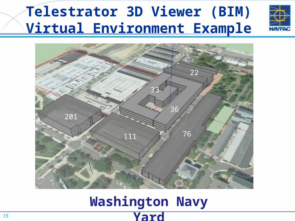
Telestrator 3D Viewer (BIM) Virtual Environment Example
36
33
22
201
111 76
Washington Navy Yard
16
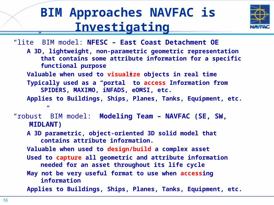
BIM Approaches NAVFAC is Investigating
“lite” BIM model: NFESC – East Coast Detachment OE A 3D, lightweight, non-parametric geometric representation that contains
some attribute information for a specific functional purpose
Valuable when used to visualize objects in real time
Typically used as a “portal” to access Information from SPIDERS, MAXIMO, iNFADS, eOMSI, etc.
Applies to Buildings, Ships, Planes, Tanks, Equipment, etc.
“robust” BIM model: Modeling Team – NAVFAC (SE, SW, MIDLANT)A 3D parametric, object-oriented 3D solid model that contains attribute
information.
Valuable when used to design/build a complex asset
Used to capture all geometric and attribute information needed for an asset throughout its life cycle
May not be very useful format to use when accessing information
Applies to Buildings, Ships, Planes, Tanks, Equipment, etc.
17
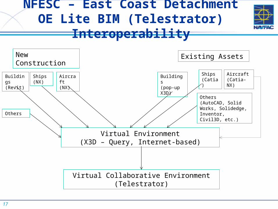
NFESC – East Coast Detachment OE Lite BIM (Telestrator) Interoperability
Virtual Environment(X3D – Query, Internet-based)
Virtual Collaborative Environment(Telestrator)
Buildings(Revit)
Existing AssetsNew Construction
Ships(NX)
Others
Aircraft(NX)
Buildings(pop-up X3D)
Ships(Catia)
Others(AutoCAD, Solid Works, Solidedge, Inventor, Civil3D, etc.)
Aircraft(Catia-NX)
18
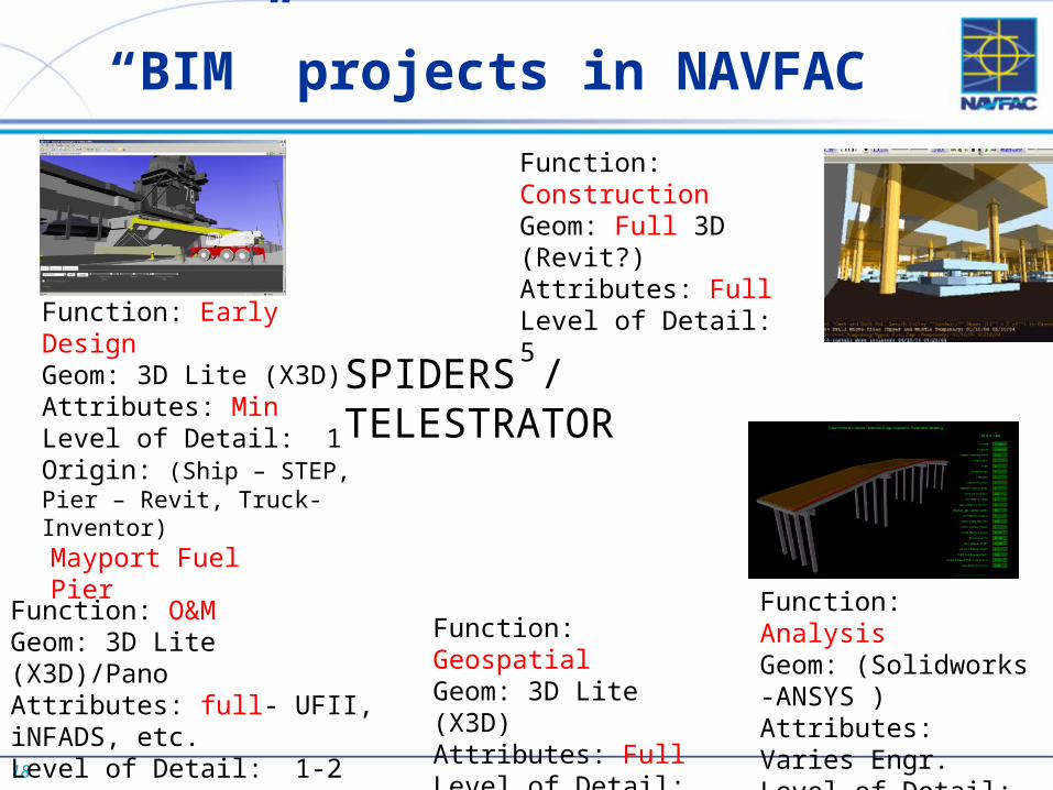
“BIM” projects in NAVFAC
Function: Early DesignGeom: 3D Lite (X3D)Attributes: MinLevel of Detail: 1Origin: (Ship – STEP, Pier – Revit, Truck-Inventor)
Function: O&MGeom: 3D Lite (X3D)/PanoAttributes: full- UFII, iNFADS, etc.Level of Detail: 1-2
Function: ConstructionGeom: Full 3D (Revit?)Attributes: FullLevel of Detail: 5
Function: AnalysisGeom: (Solidworks -ANSYS )Attributes: Varies Engr.Level of Detail: 1-5
Function: GeospatialGeom: 3D Lite (X3D)Attributes: FullLevel of Detail: 1
SPIDERS / TELESTRATOR
Mayport Fuel Pier