Embed Size (px)
Citation preview

1
Braking System Operation
Roger Bortignon

2
Slideshow Contents
• Part 1: base braking system slides 1-21
• Part 2: anti-lock braking systems slides 22-31

3
• braking force is not 50% front & 50% rear
• front brakes can apply up to 80% of the braking power
this depends partly on whether vehicle is front or rear drive (weight distribution)
this is why front brakes may have to be replaced 4 or 5 times before the rear brakes need replacement
Weight Distribution During Braking…

4
Weight Distribution During Braking…

5
Braking System Components

6
Master Cylinder
• converts pedal movement to hydraulic pressure

7
Master Cylinder Action
• applied position (pushing on brake pedal)…

8
Master Cylinder Operation
• brakes being applied
• brake pedal released

9
Caliper Designs
• fixed caliper pistons on both sides of the brake disc
caliper can have 2 or 4 pistons there are some 8 piston versions for race applications

10
Caliper Design
• floating caliper uses 1 or 2 pistons on one side of the caliper caliper body slides (in reaction to the piston movement) outer brake pad rubs on the outside of the disc

11
Brake Pad Retraction
• flexing of the caliper’s square cut o-ring causes piston to retract when the brake pedal is released no return springs required
12
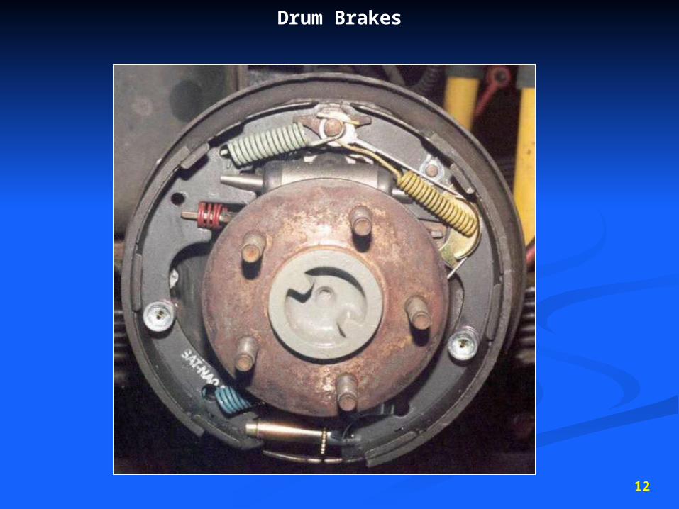
Drum Brakes

13
Self Energized, Non-Servo (Leading-Trailing) Drum Brakes
• bottom of the brake shoes mount to a solid anchor• leading (front) brake shoe is self-energized
drum rotation increases braking force front (leading) brake shoe is wedged tightly against the drum
• brake shoes are equal length• front (leading) brake shoe may be thicker than the rear (trailing)• used on the rear of many front wheel drive vehicles

14
Self Energized, “Dual-Servo” Drum Brakes
• one shoe “serves” the other to increase application force• note how the bottom of the brake shoes are not mounted on a fixed anchor• the brake shoes can pivot or rotate with the drum• front (primary) shoe helps increase pressure on rear (secondary) shoe
this is referred to as servo action• brake shoes are different lengths (longer on back side {secondary shoe})• drum rotation energizes both brake shoes• used on many rear wheel drive vehicles

15
Hydraulic Line Connections
• single piston master cylinder
used until 1967
• tandem split (fig. 11a)
used on rear drive vehicles
• diagonal split (fig. 11b)
used on front drive vehicles
Fig. 11a Fig 11b
16
Brake Hydraulic Control Valves
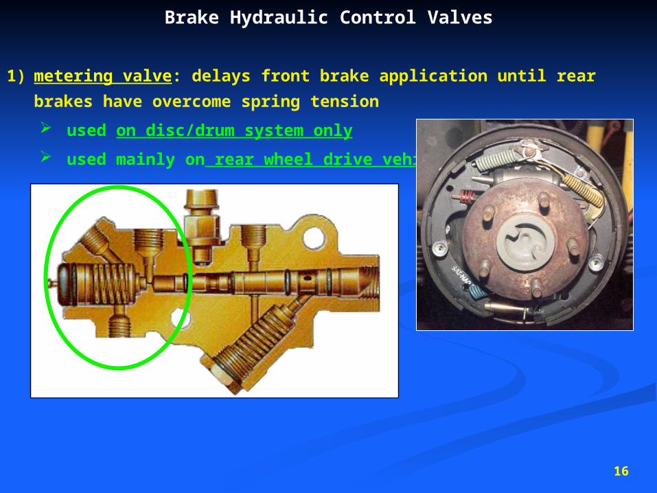
1) metering valve: delays front brake application until rear brakes have overcome spring
tension
used on disc/drum system only
used mainly on rear wheel drive vehicles

17
Brake Hydraulic Control Valves
• proportioning valve: limits hydraulic pressure to rear brakes under hard braking to prevent
wheel lock-up
• has no effect during light to moderate stops
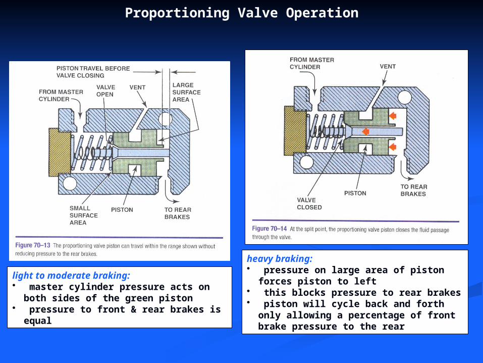
Proportioning Valve Operation
light to moderate braking:• master cylinder pressure acts on both sides of the
green piston• pressure to front & rear brakes is equal
heavy braking:• pressure on large area of piston forces piston to left• this blocks pressure to rear brakes• piston will cycle back and forth only allowing a
percentage of front brake pressure to the rear
19
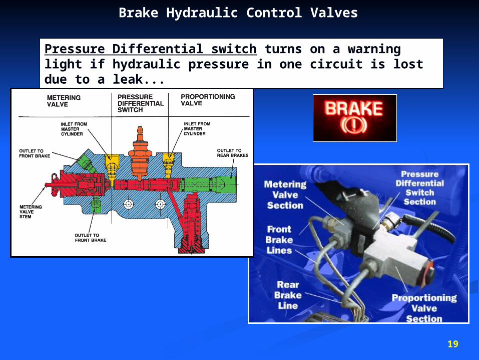
Brake Hydraulic Control Valves
Pressure Differential switch turns on a warning light if hydraulic pressure in one circuit is lost due to a leak...

20
Parking Brakes with Rear Drums
• mechanical cable actuates the brake shoes (on rear wheels)

21
Parking Brakes on Rear Discs• 2 methods of applying the e-brake on vehicles that use rear disc brakes…
1) cable moves caliper piston out
2) cable pushes out mini brake shoes against the inside of the brake rotor

22
Anti-lock Brake Systems
ABS

23
ABS• designed to prevent wheel lock-up to minimize stopping distance
& help maintain steering control by preventing wheel lock-up, tires will maintain traction with
road surface
• can also used on motorcycles and even trucks & buses with air brakes

24
ABS Components

25
How Many Channels?
• a channel describes a hydraulic brake line that is capable of being controlled by the ABS module

26
Wheel Speed Sensor
• wheel speed sensor is a magnetic impulse sensor works like a crankshaft position sensor
• creates an AC voltage signal as the tone ring rotates with the wheel• the AC voltage signal frequency changes as the wheel speed changes

27
• AC voltage ripple frequency will change with wheel speed changes

28
Modulating Brake Fluid Pressure• Electronic Brake Control Modulator EBCM• EBCM-activated solenoids modulate brake fluid pressure• the solenoid valves can (while driver is stepping on pedal) either…
hold (maintain) pressure dump (release) pressure increase pressure these solenoids can cycle the brakes 15 times/second
Hold Pressure Dump Pressure Increase Pressure
proportioning valve is no longer needed!
29
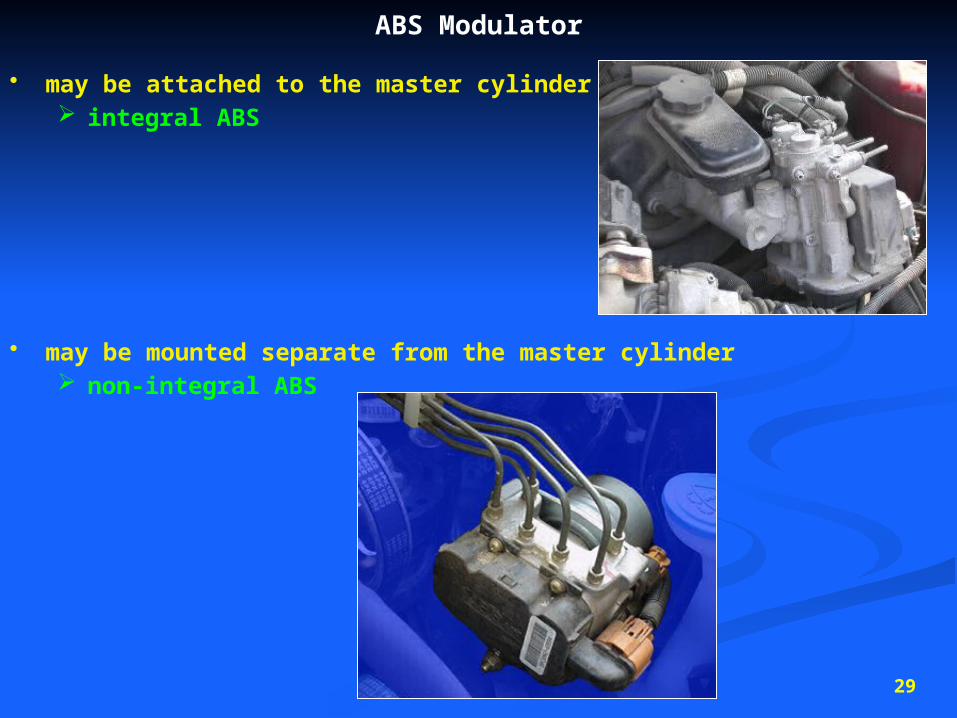
ABS Modulator
• may be attached to the master cylinder integral ABS
• may be mounted separate from the master cylinder non-integral ABS

30
• schematic of brake lines and ABS components…


![REGENERATIVE BRAKING SYSTEM IN ELECTRIC VEHICLES · REGENERATIVE BRAKING SYSTEM IN ELECTRIC VEHICLES ... REGENERATIVE BRAKING SYSTEM ... Regenerative action during braking[9]](https://img.pdfslide.us/doc/110x75/5adccef67f8b9a1a088c7cf0/regenerative-braking-system-in-electric-vehicles-braking-system-in-electric-vehicles.jpg)