Embed Size (px)
Citation preview
1
Asymmetrical Digital Subscriber Line (ADSL)
S-72.423 Telecommunication Systems
2
Asymmetrical Digital Subscriber Line
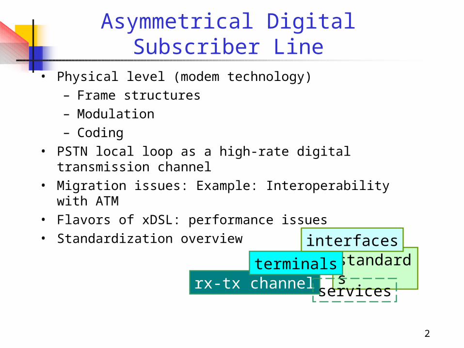
• Physical level (modem technology)– Frame structures– Modulation– Coding
• PSTN local loop as a high-rate digital transmission channel
• Migration issues: Example: Interoperability with ATM• Flavors of xDSL: performance issues• Standardization overview
rx-tx channel
standardsterminals
interfaces
services

3
Overview
4
Short history of ADSL
1985 --
1990 --
1993 --
1995 --
1998 --
1999 --
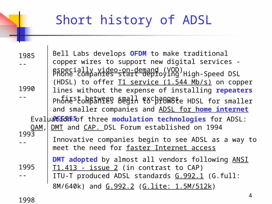
Bell Labs develops OFDM to make traditional copper wires to support new digital services - especially video-on-demand (VOD)Phone companies start deploying High-Speed DSL (HDSL) to offer T1 service (1.544 Mb/s) on copper lines without the expense of installing repeaters - first between small exchangesPhone companies begin to promote HDSL for smaller and smaller companies and ADSL for home internet access
Innovative companies begin to see ADSL as a way to meet the need for faster Internet access
DMT adopted by almost all vendors following ANSI T1.413 - issue 2 (in contrast to CAP)ITU-T produced ADSL standards G.992.1 (G.full: 8M/640k)
and G.992.2 (G.lite: 1.5M/512k)
Evaluation of three modulation technologies for ADSL: QAM, DMT and CAP. DSL Forum established on 1994
5
… history
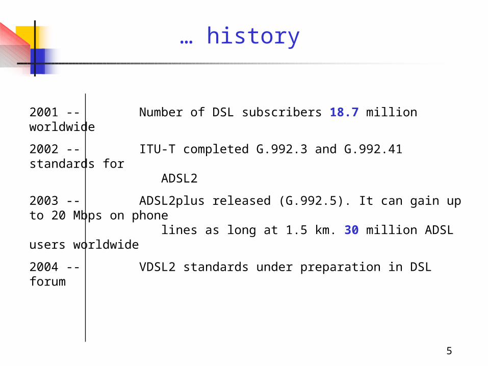
2001 -- Number of DSL subscribers 18.7 million worldwide
2002 -- ITU-T completed G.992.3 and G.992.41 standards for ADSL2
2003 -- ADSL2plus released (G.992.5). It can gain up to 20 Mbps on phone lines as long at 1.5 km. 30 million ADSL users worldwide
2004 -- VDSL2 standards under preparation in DSL forum
6
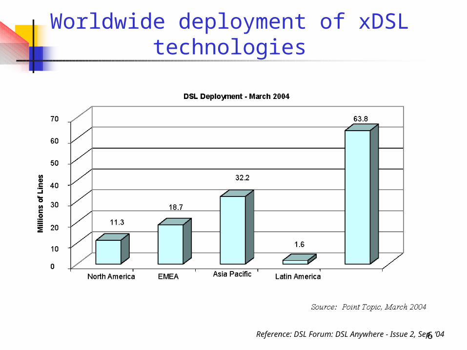
Worldwide deployment of xDSL technologies
Reference: DSL Forum: DSL Anywhere - Issue 2, Sep. ‘04
7
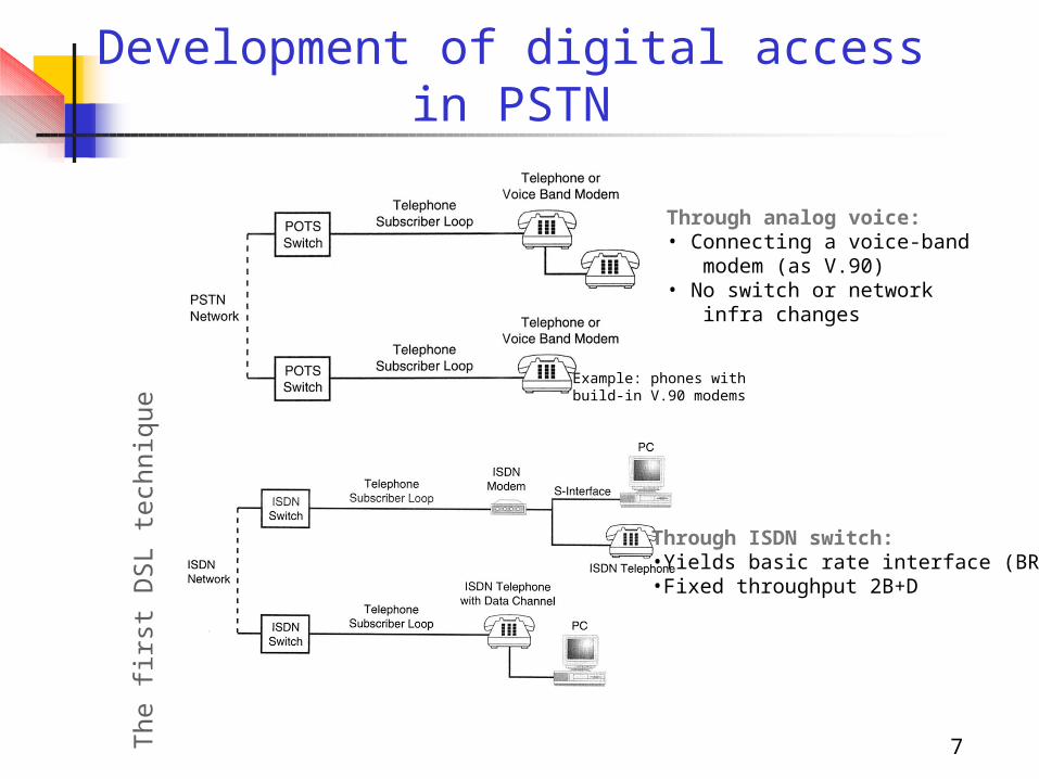
Development of digital access in PSTN
Through analog voice:• Connecting a voice-band modem (as V.90)• No switch or network infra changes
Through ISDN switch: •Yields basic rate interface (BRI)•Fixed throughput 2B+D
The
firs
t D
SL
tech
niqu
e
Example: phones with build-in V.90 modems
8
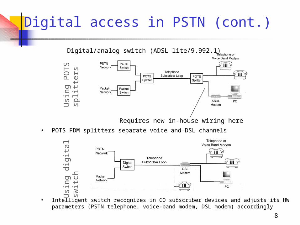
Digital access in PSTN (cont.)
• POTS FDM splitters separate voice and DSL channels
Requires new in-house wiring here
Usi
ng P
OT
S
split
ters
Digital/analog switch (ADSL lite/9.992.1)
Usi
ng d
igita
lsw
itch
• Intelligent switch recognizes in CO subscriber devices and adjusts its HW parameters (PSTN telephone, voice-band modem, DSL modem) accordingly
9
Motivation for adaptation of ADSL
• Need for high-speed Internet access - also telephone modem speeds have peaked and cable modems have turned out to lack speed with many users
• Transmits high speed data to local loop by using unshielded 2-wire twisted pairs (often no repeaters required)
• DSL allows rates varying from 160 kb/s up to 50 Mb/s on down link (DL) depending on technology used!
• In the most popular commercial ADSL (G.992.1) maximum rate 640 kbit/s upstream and 8 Mb/s downstream
• Different xDSL techniques developed to serve symmetric and asymmetric traffic requirements and different rates (STM and ATM supported by G.992.1 ADSL)
STM-n: Synchronous Transfer Module (of SDH): DS-1,2: 1.544 Mb/s, 6.312 Mb/sATM: Asynchronous Transfer ModeDL: Down Link - Down stream
10
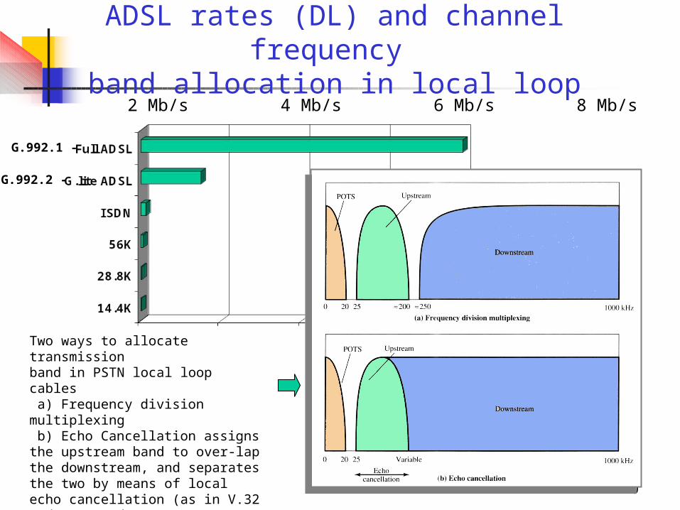
ADSL rates (DL) and channel frequency
band allocation in local loop2 Mb/s 4 Mb/s 6 Mb/s 8 Mb/s
Two ways to allocate transmissionband in PSTN local loop cables a) Frequency division multiplexing b) Echo Cancellation assigns the upstream band to over-lap the downstream, and separates the two by means of local echo cancellation (as in V.32 and V.34 modems)
G.992.1 -
G.992.2 -
11
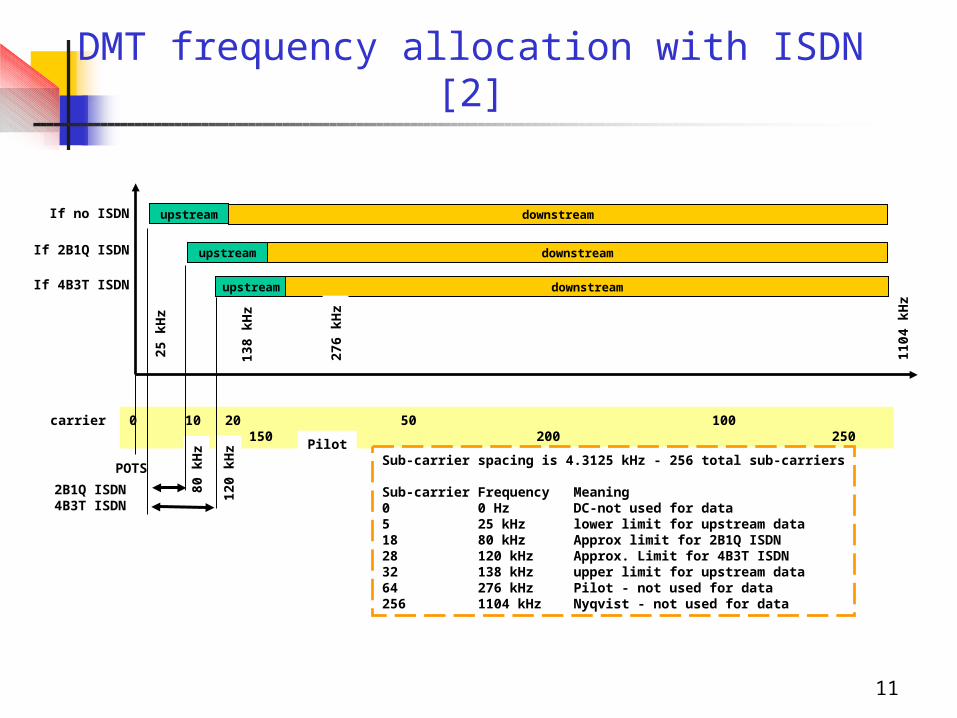
DMT frequency allocation with ISDN [2]
upstream downstream
upstream downstream
upstream downstream
If no ISDN
If 2B1Q ISDN
If 4B3T ISDN
0 10 20 50 100 150 200 250carrier
25 k
Hz
120
kHz
1104
kH
z
276
kHz
POTS
138
kHz
80 k
Hz
2B1Q ISDN4B3T ISDN
PilotSub-carrier spacing is 4.3125 kHz - 256 total sub-carriers
Sub-carrier Frequency Meaning0 0 Hz DC-not used for data5 25 kHz lower limit for upstream data18 80 kHz Approx limit for 2B1Q ISDN28 120 kHz Approx. Limit for 4B3T ISDN32 138 kHz upper limit for upstream data64 276 kHz Pilot - not used for data256 1104 kHz Nyqvist - not used for data
12
Physical realization and frame structures
13
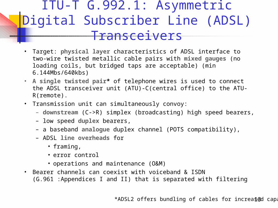
ITU-T G.992.1: Asymmetric Digital Subscriber Line (ADSL)
Transceivers• Target: physical layer characteristics of ADSL interface to two-
wire twisted metallic cable pairs with mixed gauges (no loading coils, but bridged taps are acceptable) (min 6.144Mbs/640kbs)
• A single twisted pair* of telephone wires is used to connect the ADSL transceiver unit (ATU)-C(central office) to the ATU-R(remote).
• Transmission unit can simultaneously convoy: – downstream (C->R) simplex (broadcasting) high speed
bearers, – low speed duplex bearers, – a baseband analogue duplex channel (POTS compatibility), – ADSL line overheads for
• framing, • error control • operations and maintenance (O&M)
• Bearer channels can coexist with voiceband & ISDN (G.961 :Appendices I and II) that is separated with filtering
*ADSL2 offers bundling of cables for increased capacity
14
Topics of ITU-T G.992.1
• Basic capabilities specified in G992.1:– combined options and ranges of the simplex and full-
duplex bearer channels – line code and the spectral composition of the ATU-C
and ATU-R signals– electrical and mechanical specifications of the
network interface– organization of transmitted and received data into frames– functions of the operations channel– ATU-R to service module(s) interface functions– ATM support (Transmission Convergence Sub-layer)
• Optional capabilities: echo cancellation, trellis coded modulation, transport of a network timing reference, transport of STM and/or ATM, reduced overhead framing modes
15
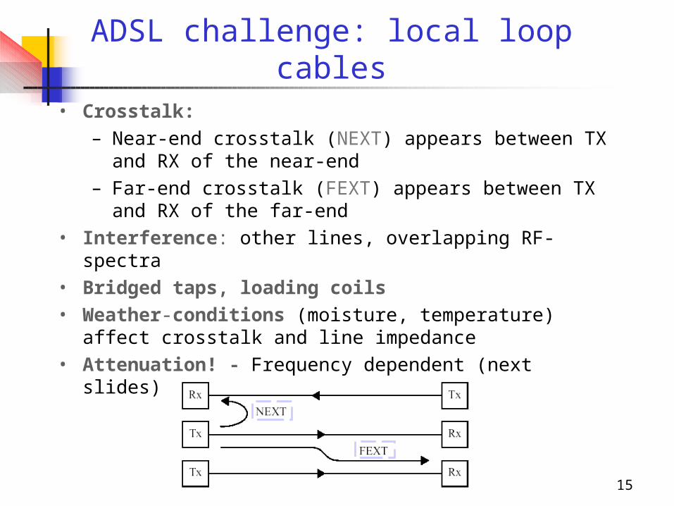
ADSL challenge: local loop cables
• Crosstalk:– Near-end crosstalk (NEXT) appears between TX and
RX of the near-end– Far-end crosstalk (FEXT) appears between TX and RX
of the far-end• Interference: other lines, overlapping RF-spectra• Bridged taps, loading coils• Weather-conditions (moisture, temperature) affect
crosstalk and line impedance• Attenuation! - Frequency dependent (next slides)
16
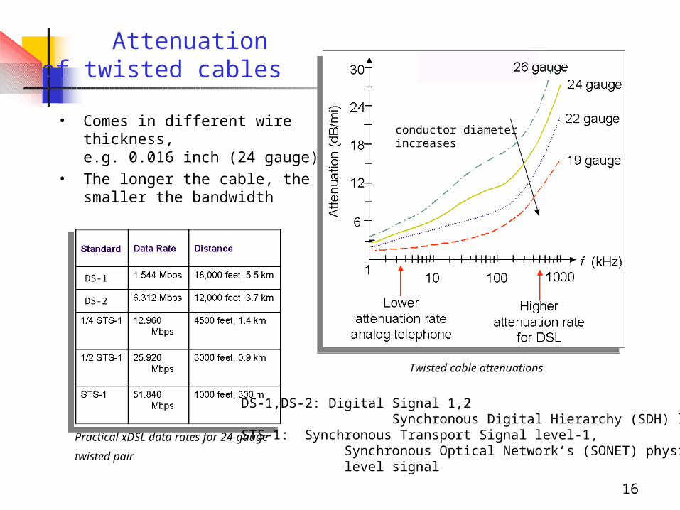
Attenuation of twisted cables
• Comes in different wire thickness, e.g. 0.016 inch (24 gauge)
• The longer the cable, the smaller the bandwidth
Twisted cable attenuations
Practical xDSL data rates for 24-gauge
twisted pair
DS-1
DS-2
DS-1,DS-2: Digital Signal 1,2 Synchronous Digital Hierarchy (SDH) levelsSTS-1: Synchronous Transport Signal level-1, Synchronous Optical Network’s (SONET) physical level signal
conductor diameter increases
17
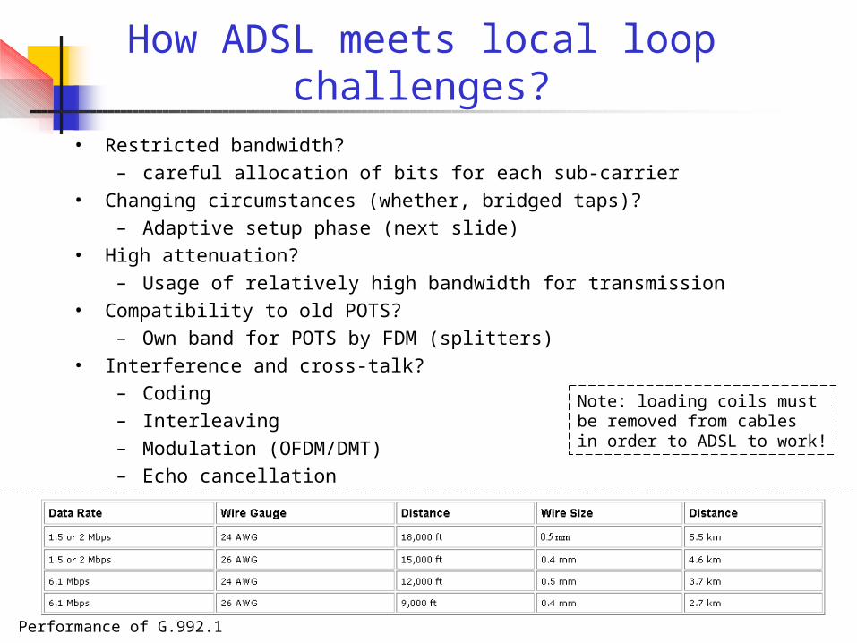
How ADSL meets local loop challenges?
• Restricted bandwidth?– careful allocation of bits for each sub-carrier
• Changing circumstances (whether, bridged taps)?– Adaptive setup phase (next slide)
• High attenuation?– Usage of relatively high bandwidth for transmission
• Compatibility to old POTS?– Own band for POTS by FDM (splitters)
• Interference and cross-talk?– Coding– Interleaving– Modulation (OFDM/DMT)– Echo cancellation
Note: loading coils mustbe removed from cablesin order to ADSL to work!
Performance of G.992.1
18
Start-up phases of Rate Adaptive ADSL (RADSL)
• RADSL modems apply sophisticated hand shaking to initiate transmissions that include– Activation: notice the need for communications– Gain setting/control: Adjust the power for
optimum transmission and minimum emission– Channel allocation / bit rate assignment (DMT)– Synchronization: Clocks and frames to the same
phases– Echo cancellation: (if used, required for both ends)– Channel identification and equalization
19
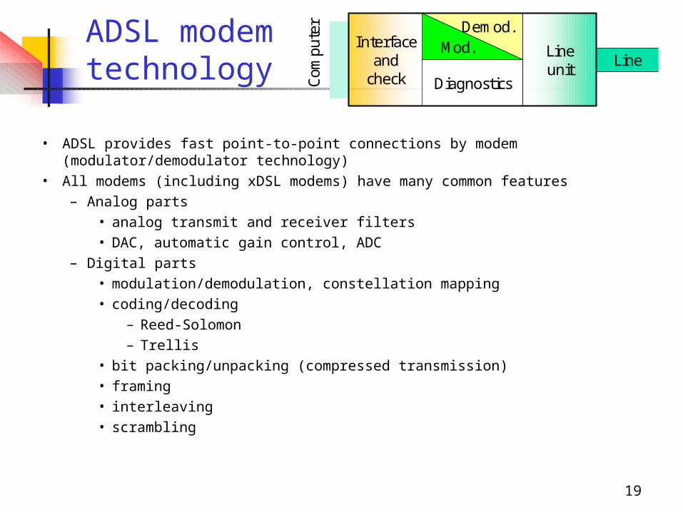
ADSL modem
technology
• ADSL provides fast point-to-point connections by modem (modulator/demodulator technology)
• All modems (including xDSL modems) have many common features– Analog parts
• analog transmit and receiver filters• DAC, automatic gain control, ADC
– Digital parts• modulation/demodulation, constellation mapping• coding/decoding
– Reed-Solomon– Trellis
• bit packing/unpacking (compressed transmission)• framing• interleaving• scrambling
Interfaceand
check
Mod.Demod.
Diagnostics
Lineunit
Line
Com
pute
r
20
ADSL- modem technology (cont.)
• xDSL modems apply also more advanced techniques:– Carrierless AM/PM (CAP) or QAM line codes (97% of
USA installations apply this method)– Fast Fourier Transforms for Discrete Multi-Tone
Modulation (DMT) - the dominant method• tone ordering -> water pouring bit allocations
(adaptation to transfer function) & peak-to-average ratio (PAPR) decrease
• channel equalization (tone-by-tone different rates)
• guard intervals (adaptation to channel delay spread)
– Turbo - coding– Adaptive echo canceller
21
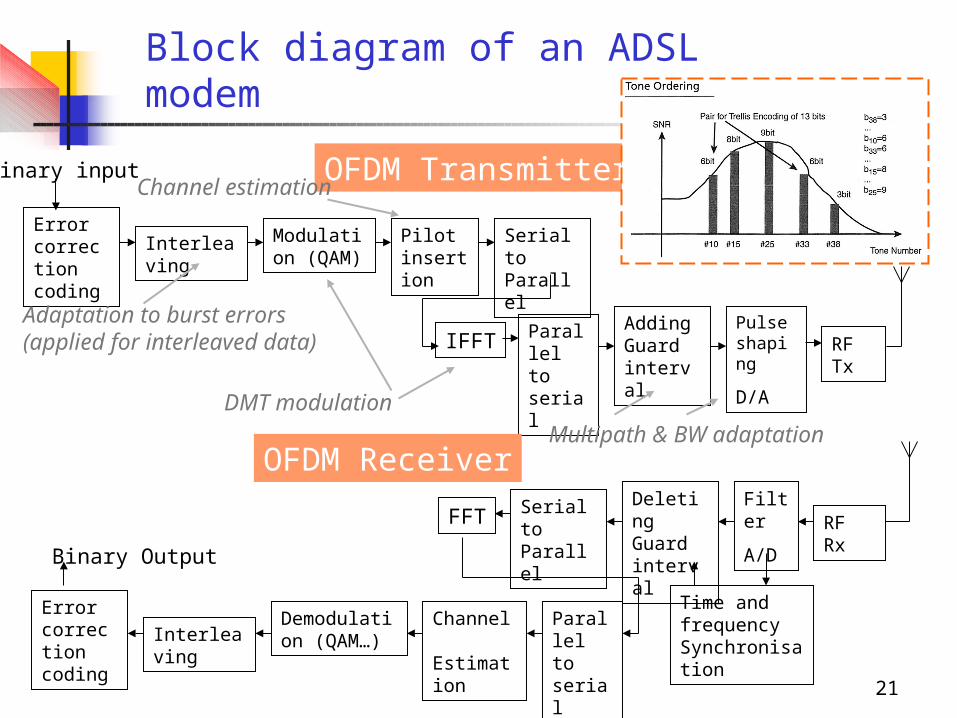
Block diagram of an ADSLmodem
Error correction coding
Interleaving Modulation (QAM)
Pilot insertion
Parallel to serial
Pulseshaping
D/A
Adding Guard interval
RF Tx
Binary input
Error correction coding
InterleavingDemodulation (QAM…)
Channel Estimation
Serial to Parallel
Filter
A/D
Deleting Guard interval
RF Rx
Binary Output
Serial to Parallel
IFFT
FFT
Parallel to serial
Time and frequency Synchronisation
OFDM Transmitter
OFDM Receiver
Channel estimation
DMT modulation
Multipath & BW adaptation
Adaptation to burst errors(applied for interleaved data)
22
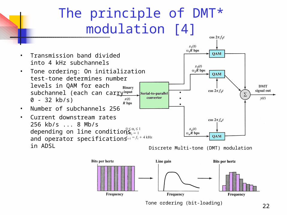
The principle of DMT* modulation [4]
• Transmission band divided into 4 kHz subchannels
• Tone ordering: On initialization test-tone determines number levels in QAM for each subchannel (each can carry0 - 32 kb/s)
• Number of subchannels 256 • Current downstream rates
256 kb/s ... 8 Mb/sdepending on line conditionsand operator specificationsin ADSL Discrete Multi-tone (DMT) modulation
Tone ordering (bit-loading)
23
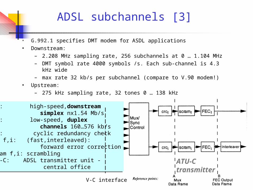
ADSL subchannels [3]
• G.992.1 specifies DMT modem for ASDL applications• Downstream:
– 2.208 MHz sampling rate, 256 subchannels at 0 … 1.104 MHz– DMT symbol rate 4000 symbols /s. Each sub-channel is 4.3 kHz wide– max rate 32 kb/s per subchannel (compare to V.90 modem!)
• Upstream:– 275 kHz sampling rate, 32 tones 0 … 138 kHz
ASx: high-speed,downstream simplex nx1.54 Mb/sLSx: low-speed, duplex channels 160…576 kb/scrc: cyclic redundancy checkFEC f,i: (fast,interleaved): forward error correctionscram f,i: scramblingATU-C: ADSL transmitter unit - central office
ASx: high-speed,downstream simplex nx1.54 Mb/sLSx: low-speed, duplex channels 160…576 kb/scrc: cyclic redundancy checkFEC f,i: (fast,interleaved): forward error correctionscram f,i: scramblingATU-C: ADSL transmitter unit - central office
V-C interface
ATU-Ctransmitter
24
Multi-tone modulation (cont.)
• In channel activation phase different sub-channels are allocated for their optimum rates (by changing number of levels in modulation)
• DMT-ADSL supports both synchronous transfer modules (STM) of SDH and asynchronous transfer mode (ATM, AS0 used for primary cell stream)
• ADSL modems offer two data paths:– Fast
• low latency (2ms)• real-time traffic
– Interleaved• low error rate • Reed-Solomon encoding (concatenated convolutional
codes) at the expense of increased latency
25
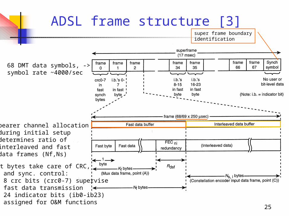
ADSL frame structure [3]
68 DMT data symbols, ->symbol rate ~4000/sec
super frame boundaryidentification
- bearer channel allocation during initial setup determines ratio of interleaved and fast data frames (Nf,Ns)
- fast bytes take care of CRC, O&M and sync. control: - 8 crc bits (crc0-7) supervise fast data transmission - 24 indicator bits (ib0-ib23) assigned for O&M functions
26
ADSL system total data rate
• Total data rate=Net data rate + System overheads• The net data rate is transmitted in the ADSL bearer channels• ADSL system overheads
– an ADSL embedded operations channel, eoc (O&M)– an ADSL overhead control channel, aoc– crc check bytes– fixed indicator bits for O&M*– Reed-Solomon FEC redundancy bytes
• These data streams are organized into ADSL frames and super-frames for the downstream and upstream data
O&M: error detection, corrected errors, loss of signal, remote defects ...

27
Reference models
28
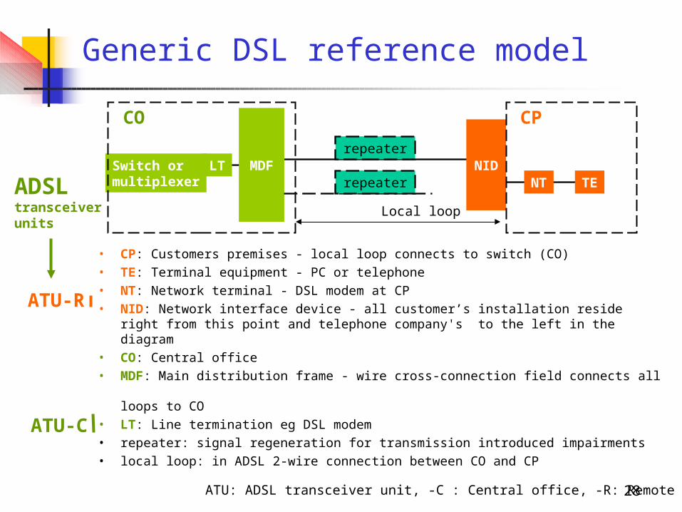
Generic DSL reference model
• CP: Customers premises - local loop connects to switch (CO)• TE: Terminal equipment - PC or telephone• NT: Network terminal - DSL modem at CP• NID: Network interface device - all customer’s installation reside right from
this point and telephone company's to the left in the diagram• CO: Central office• MDF: Main distribution frame - wire cross-connection field connects all
loops to CO• LT: Line termination eg DSL modem• repeater: signal regeneration for transmission introduced impairments• local loop: in ADSL 2-wire connection between CO and CP
Switch ormultiplexer
LT MDFrepeater
NIDNT TE
CO CP
repeater
Local loop
ATU-R
ADSLtransceiverunits
ATU-C
ATU: ADSL transceiver unit, -C : Central office, -R: Remote unit
29
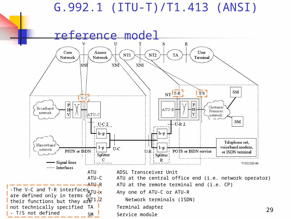
G.992.1 (ITU-T)/T1.413 (ANSI) reference model
ATU ADSL Transceiver Unit ATU‑C ATU at the central office end (i.e. network operator)ATU‑R ATU at the remote terminal end (i.e. CP)
ATU-x Any one of ATU-C or ATU-R
NT1,2 Network terminals (ISDN)
TA Terminal adapter
SM Service module
-The V-C and T-R interfaces are defined only in terms of their functions but they are not technically specified- T/S not defined
30
Interoperability issues
31
Using ADSL
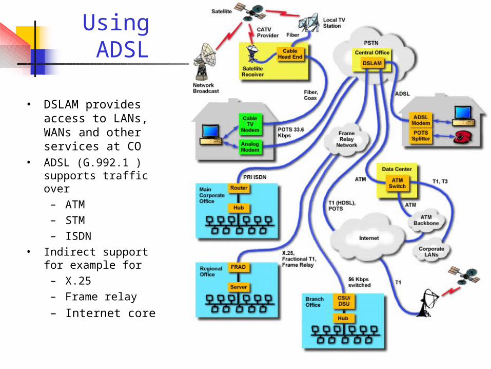
• DSLAM provides access to LANs, WANs and other services at CO
• ADSL (G.992.1 ) supports traffic over– ATM– STM– ISDN
• Indirect support for example for– X.25– Frame relay
– Internet core
32
DSL Forum’s End-to-end Reference Model
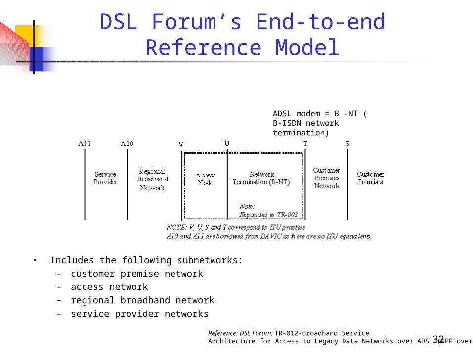
• Includes the following subnetworks: – customer premise network– access network– regional broadband network – service provider networks
ADSL modem = B -NT ( B-ISDN network termination)
Reference: DSL Forum: TR-012-Broadband Service Architecture for Access to Legacy Data Networks over ADSL (PPP over ATM)
33
ATM over ADSL for broadband networking
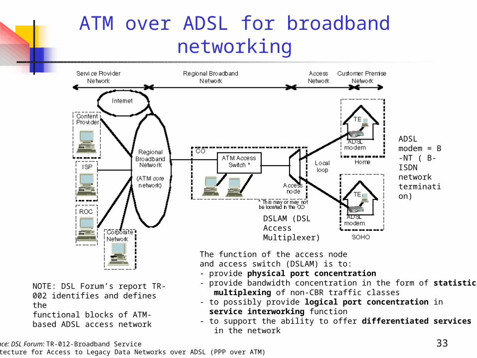
Reference: DSL Forum: TR-012-Broadband Service Architecture for Access to Legacy Data Networks over ADSL (PPP over ATM)
DSLAM (DSL AccessMultiplexer)
ADSL modem = B -NT ( B-ISDN network termination)
NOTE: DSL Forum’s report TR-002 identifies and defines thefunctional blocks of ATM-based ADSL access network
The function of the access nodeand access switch (DSLAM) is to:- provide physical port concentration- provide bandwidth concentration in the form of statistical multiplexing of non-CBR traffic classes- to possibly provide logical port concentration in service interworking function- to support the ability to offer differentiated services in the network
34
Standardization
35
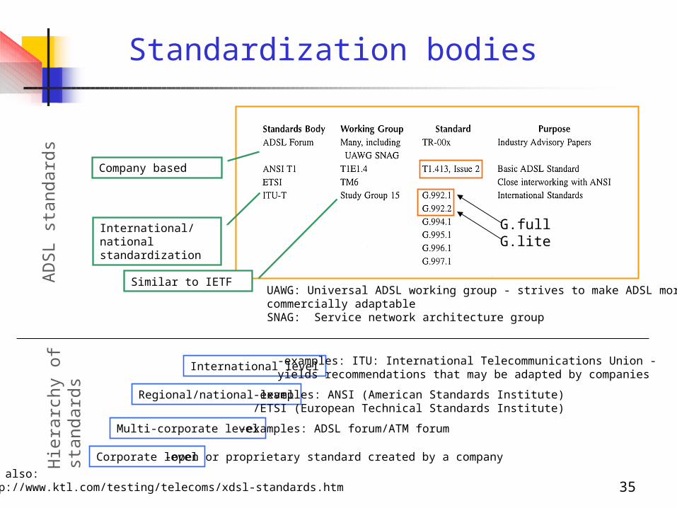
Standardization bodies
Corporate level
Multi-corporate level
-open or proprietary standard created by a company
-examples: ADSL forum/ATM forum
Regional/national level -examples: ANSI (American Standards Institute)/ETSI (European Technical Standards Institute)
International level -examples: ITU: International Telecommunications Union -yields recommendations that may be adapted by companies
Hie
rarc
hy o
fst
anda
rds
Company based
UAWG: Universal ADSL working group - strives to make ADSL morecommercially adaptableSNAG: Service network architecture group
International/national standardization
AD
SL
stan
dard
s
G.liteG.full
See also: http://www.ktl.com/testing/telecoms/xdsl-standards.htm
Similar to IETF
36
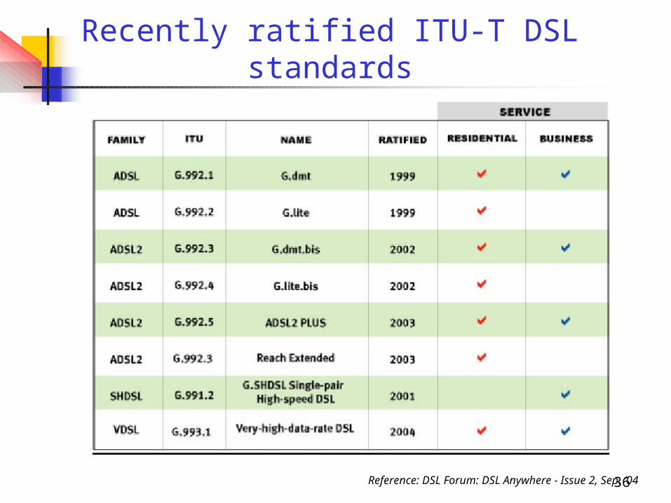
Recently ratified ITU-T DSL standards
Reference: DSL Forum: DSL Anywhere - Issue 2, Sep. ‘04
37
xDSL flavors and performance comparison
38
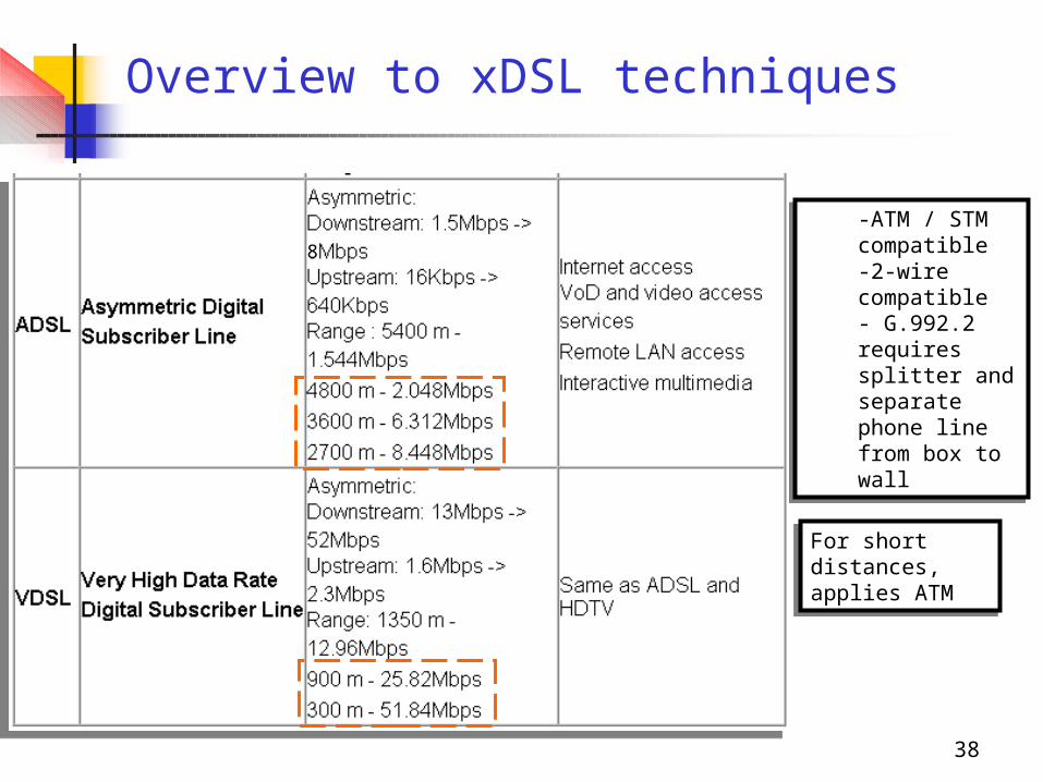
Overview to xDSL techniques
8
-ATM / STM compatible-2-wire compatible- G.992.2 requires splitter and separate phone line from box to wall
-ATM / STM compatible-2-wire compatible- G.992.2 requires splitter and separate phone line from box to wall
For short distances, applies ATM
For short distances, applies ATM
39
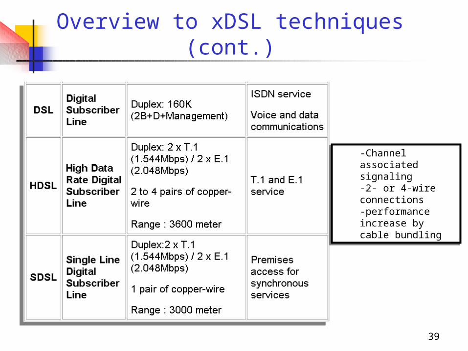
-Channel associated signaling-2- or 4-wire connections-performance increase by cable bundling
-Channel associated signaling-2- or 4-wire connections-performance increase by cable bundling
Overview to xDSL techniques (cont.)
40
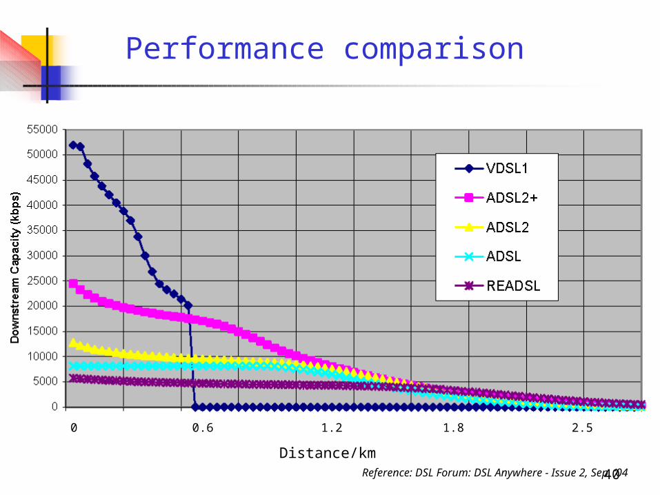
Performance comparison
0 0.6 1.2 1.8 2.5 3.0 3.6 4.3 4.9 5.5 6.0
Distance/kmReference: DSL Forum: DSL Anywhere - Issue 2, Sep. ‘04
41
References
[1] T. Starr, J.M. Cioffi, P.J. Silverman: Understanding Digital Subscriber Line Technology, Prentice-Hall
[2] W.Y. Chen: DSL Simulation Techniques and Standards - Development for Digital Subscriber Line Systems, MacMillan Tech. Publishing
[3] C.K. Summers: ADSL - Standards, Implementation and Architecture, CRC Press
[4] William Stallings: Data and Computer Communications (7th Ed), Prentice Hall
[5] ANSI T1.413, issue 2 standard