Embed Size (px)
Citation preview
Home page | Help | Clear English | French | Spanish | German
Search | Subjects | Titles A-Z | Courses | Illustrations | Topics | e-Course builder
Contract TOC Expand Document Contract Chapter Add to e-Course Preferences
Printable version
Export document
as HTML file Help
Export document
as PDF file
Building Construction with 14 Modules (TCA; 1983; 618 pages)
1. ARCHITECTURAL DRAWING I
1.1 AIMS AND PURPOSE OF ARCHITECTURAL DRAWINGS
1.1.1 CONTENTS OF ARCHITECTURAL DRAWINGS
1.2 DRAWING EQUIPMENT
1.2.1 PENCILS
1.2.2 DRAWING PENS
1.2.3 COMPASSES
1.2.4 DRAWING BOARDS
1.2.5 T-SQUARES
1.2.6 SET SQUARES
1.2.7 PROTRACTORS
1.2.8 SCALES
1.2.9 FRENCH CURVES
1.2.10 TEMPLATES
1.2.11 DRAWING PINS AND OTHER FIXINGS
1.2.12 MINOR ITEMS OF EQUIPMENT
1.2.13 PRINTING PAPERS
1.2.14 TRACING PAPER, CLOTH AND FILM
25/09/2011 Building Construction with 14 Modules: 9. ROOFS
file:///D:/cd3wddvd/crystal_A6/construction/stuff.htm 1/137
1.2.15 BACKING SHEETS
1.2.16 DRAWING PAPERS
1.2.17 CARTRIDGE
1.2.18 HANDMADE AND MOULDMADE PAPERS
1.2.19 PLASTIC-COATED CARD
1.3 LETTERING
1.3.1 PRINCIPLE OF LETTERING
1.3.2 FREEHAND LETTERING
1.3.3 TYPES OF LETTERS
1.3.3.1 The Roman Alphabet
1.3.3.2 Sans Serif Letters
1.3.3.3 Inclined Lettering
1.3.3.4 Script Lettering
1.3.3.5 Stencil Lettering
1.3.3.6 Guided Pen Lettering
1.3.3.7 Pressure-Transfer Lettering
1.4 LINEWORK AND DIMENSIONING
1.4.1 TYPES OF LINES
1.4.2 PENCIL DRAWING
1.4.3 INKING - IN
1.4.4 BASIC RULES OF DIMENSIONING
1.4.4.1 Types of Dimensions
1.4.4.2 Placement of Dimensions
25/09/2011 Building Construction with 14 Modules: 9. ROOFS
file:///D:/cd3wddvd/crystal_A6/construction/stuff.htm 2/137

1.5 ENLARGEMENT AND REDUCTION OF LINE DRAWINGS
1.6 GEOMETRICAL CONSTRUCTIONS
1.6.1 LINES AND ANGLES
1.6.1.1 To bisect a straight line AB
1.6.1.2 To divide a straight line AB into a given number of equal parts
1.6.1.3 To divide a straight line AB into any ratio
1.6.1.4 To construct an angle of 90°
1.6.1.5 To construct an angle of 45°
1.6.1.6 To construct an angle of 60°
1.6.1.7 To construct an angle of 30°
1.6.1.8 To bisect any given angle
1.6.1.9 To construct an angle SIMILAR to a given angle
1.6.1.10 To draw a line PARALLEL to a given line
1.6.2 TRIANGLES
1.6.2.1 To construct an EQUILATERAL triangle
1.6.2.2 To construct a triangle with given BASE ANGLES and
ALTITUDE
1.6.2.3 To inscribe a circle in a given triangle ABC
1.6.2.4 To circiumscribe a triangle ABC
1.6.3 CIRCLES
1.6.3.1 Basic CIRCLE-Constructions
1.6.3.2 To draw a tangent to a point A on the circumference of a circle
centre O
25/09/2011 Building Construction with 14 Modules: 9. ROOFS
file:///D:/cd3wddvd/crystal_A6/construction/stuff.htm 3/137
1.6.3.3 To draw an internal tangent to two circles of equal diameter
1.6.3.4 To find the centre of a given circle arc
1.6.3.5 To join two straight lines at RIGHT ANGLES to each other by
an arc of given radius
1.6.3.6 To draw a curve of given radius joining two circles
1.6.3.7 To join two straight lines by two arcs of equal radius
1.6.4 BASIC ARCH CONSTRUCTIONS
2. ARCHITECTURAL DRAWING II
2.1 TYPES OF PROJECTIONS
2.2 ORTHOGRAPHIC PROJECTION
2.2.1 CONSTRUCTION OF ORTHOGRAPHIC PROJECTION
2.2.2 ELEVATIONS
2.2.3 PLANS AND SECTIONS
2.3 PICTORIAL DRAWING
2.3.1 AXONOMETRIC PROJECTION
2.3.2 ISOMETRIC PROJECTION
2.3.3 DIMETRIC PROJECTION
2.3.4 OBLIQUE PROJECTION
2.3.4.1 Length of Receding Lines
2.3.4.2 Construction of Oblique Drawings
2.3.4.3 Rules of Oblique Drawing
2.3.4.4 Scale of the Receding Lines
2.3.4.5 Direction of Receding Lines
25/09/2011 Building Construction with 14 Modules: 9. ROOFS
file:///D:/cd3wddvd/crystal_A6/construction/stuff.htm 4/137

2.3.4.6 Position of Axes
2.4 PERSPECTIVE DRAWING
2.4.1 PERSPECTIVE TERMS
2.4.2 PHENOMENA OF PERSPECTIVE DRAWING
2.4.3 SYSTEMS OF PERSPECTIVE DRAWINGS
2.4.4 METHODS OF PERSPECTIVE DRAWINGS
2.4.5 TWO-POINT PERSPECTIVE
2.4.6 ONE-POINT PERSPECTIVE
2.5 SHADES AND SHADOWS
2.5.1 THE USE OF SHADOWS
2.5.2 SHADES AND SHADOWS
2.5.3 THE CONVENTIONAL DIRECTION OF LIGHT
2.5.4 THE 45° DIRECTION
2.5.5 THE TRUE DIRECTION OF LIGHT
2.5.6 SHADOWS OF SOLIDS
2.5.7 PLANES OF SHADOW
2.5.8 PRINCIPLES OF SHADOW-CASTING
2.6 DRAWING PRACTICE
2.6.1 DRAWING SHEETS
2.6.1.1 Sizes and Folds
2.6.1.2 Layout and Identification
2.6.2 LEVELS
2.6.3 REFERENCING
25/09/2011 Building Construction with 14 Modules: 9. ROOFS
file:///D:/cd3wddvd/crystal_A6/construction/stuff.htm 5/137
2.6.4 ABBREVIATIONS
2.6.5 REPRESENTATION OF MATERIALS
2.6.6 GRAPHICAL SYMBOLS AND REPRESENTATION
2.6.7 HATCHING RULES
2.7 APPLICATION FOR BUILDING PERMIT
2.7.1 PROCEDURE OF APPLYING FOR PERMISSION TO ERECT A
BUILDING
2.7.2 FORMULARS
4. CONTRACT PLANNING AND SITE ORGANISATION
4.1 CONTRACT PLANNING
4.1.1 BAR CHART
4.1.2 NETWORK ANALYSIS
4.1.3 THE OVERALL PROGRAMME
4.1.3.1 Break down of job
4.1.3.2 Quantities of work and time content
4.1.3.3 Plant and Labour outputs
4.1.3.4 Sequence and timing of operations
4.1.3.5 The programme chart
4.1.4 PLANNING CONSIDERATIONS
4.1.4.1 Site conditions and access
4.1.4.2 Nature of job
4.1.4.3 Plant
4.1.4.4 Scaffolding
25/09/2011 Building Construction with 14 Modules: 9. ROOFS
file:///D:/cd3wddvd/crystal_A6/construction/stuff.htm 6/137
4.2 SITE ORGANIZATION
4.2.1 PRELIMINARY WORK
4.2.2 SITE PLANNING
4.2.2.1 Period planning
4.2.2.2 Weekly planning
4.2.2.3 Progress control
4.2.3 SITE LAYOUT
5. FOUNDATIONS
5.1 SOIL INVESTIGATIONS
5.1.1 SITE EXPLORATION
5.1.1.1 Trial holes
5.1.1.2 Bore holes
5.1.1.3 Sampling
5.1.1.4 Tests
5.1.1.5 Load or bearing test
5.1.2 SOILS AND SOIL CHARACTERISTICS
5.1.2.1 Rocks and soils
5.1.2.2 Stresses and pressures
5.2 EXCAVATIONS AND TIMBERING
5.3 TYPES OF FOUNDATIONS
5.3.1 CLASSIFICATION
5.3.2 CHOICE OF FOUNDATION
5.3.3 SPREAD FOUNDATIONS
25/09/2011 Building Construction with 14 Modules: 9. ROOFS
file:///D:/cd3wddvd/crystal_A6/construction/stuff.htm 7/137
5.3.3 SPREAD FOUNDATIONS
5.3.3.1 Strip foundations
5.3.3.2 Deep strip foundations
5.3.3.3 Stepped foundations
5.3.3.4 Pad foundations
5.3.3.5 Raft foundations
5.3.4 PILE FOUNDATIONS
5.3.4.1 Short bored pile foundations
5.3.5 PIER FOUNDATIONS
6. WALLS
6.1 FUNCTION AND PROPERTIES OF WALLS
6.2 THE BEHAVIOR OF THE WALL UNDER LOAD
6.2.1 CALCULATION OF WALL THICKNESS
6.3 TYPES OF WALLS
6.4 STONEWORK
6.4.1 BUILDING STONES
6.4.2 STONEWORK THERMINOLOGY
6.4.3 STONEWORK CLASSIFICATION
6.4.4 RUBBLE WALLING
6.4.5 ASHLAR WALLING
6.4.5.1 Rules for ashlar work
6.5 BRICK WORK
6.5.1 BRICKWORK TERMINOLOGY
6.5.2 MANUFACTURE OF CLAY BRICKS
25/09/2011 Building Construction with 14 Modules: 9. ROOFS
file:///D:/cd3wddvd/crystal_A6/construction/stuff.htm 8/137
6.5.2 MANUFACTURE OF CLAY BRICKS
6.5.2.1 Pressed Bricks
6.5.2.2 Wire cut bricks
6.5.2.3 Efflorescence
6.5.3 BRICK CLASSIFICATION
6.5.4 CALCIUM SILICATE BRICKS
6.5.5 CONCRETE BRICKS
6.5.6 MORTARS FOR BRICKWORK
6.5.7 DAMPNESS PENETRATION
6.5.8 BRICKWORK BONDING
6.5.8.1 Common bonds
6.5.9 METRIC MODULAR BRICKWORK
6.5.10 JUNCTIONS
6.5.11 QUOINS OR EXTERNAL ANGLES
6.5.12 PIERS
6.5.12.1 Detached piers:
6.5.12.2 Attached Piers (or Pilasters)
6.5.12.3 Buttresses
6.6 BLOCKWORK
6.6.1 CLAY BLOCKS
6.6.2 PRECAST CONCRETE BLOCKS
6.6.3 AERATED CONCRETE BLOCKS
6.7 CONCRETE WALLS
6.7.1 GENERAL
25/09/2011 Building Construction with 14 Modules: 9. ROOFS
file:///D:/cd3wddvd/crystal_A6/construction/stuff.htm 9/137
6.7.1 GENERAL
6.7.2 FOREWORK
6.7.3 PLAIN MONOLITHIC CONCRETE WALL
6.7.3.1 Dense concrete walls
6.7.3.2 Light-weight aggregate
6.7.3.3 No-fines concrete walls
6.7.3.4 Thickness of plain concrete walls
6.7.3.5 Shrinkage reinforcement
6.7.4 REINFORCED CONCRETE WALLS
6.7.4.1 In-Situ Cast external walls
6.7.4.2 Concrete Box Frames
6.7.4.3 Large precast panel structure
6.8 OPENINGS IN WALLS
6.8.1 HEAD
6.8.1.1 Lintels
6.8.1.2 Arches
6.8.2 JAMBS
6.8.3 SILLS AND THRESHOLDS
6.8.3.1 Sills
6.8.3.2 Thresholds
7. FLOORS
7.1 GENERAL
7.2 SOLID GROUND FLOORS
25/09/2011 Building Construction with 14 Modules: 9. ROOFS
file:///D:/cd3wddvd/crystal_A6/construction/stuff.htm 10/137

7.2.1 SITE CONCRETE
7.2.2 HARDCORE
7.2.3 WATERPROOF MEMBRANE
7.3 SUSPENDED TIMBER GROUND FLOOR
7.3.1 BUILDING REGULATIONS
7.3.2 LAY OUT
7.4 UPPER FLOORS
7.4.1 TYPES OF UPPER FLOORS
7.4.2 STRUCTURE OF UPPER FLOORS
7.4.3 SUSPENDED TIMBER UPPER FLOORS
7.4.3.1 Floor Joists
7.4.3.2 End Support of Floor Joists
7.4.3.3 Trimming
7.4.4 REINFORCED CONCRETE UPPER FLOORS
7.4.4.1 Monolithic Reinforced Concrete Upper Floors
7.4.4.2 Precast Concrete Upper Floors
7.4.4.3 Hollow Block and Waffle Floors
7.5 FLOOR FINISHES
7.5.1 JOINTLESS FLOOR FINISHES
7.5.1.1 The most common of these is the Cement/Sand Screed
7.5.1.2 Granolithic Concrete Finishes
7.5.1.3 Terazzo
7.5.2 SLAB FLOORS FINISEHES
25/09/2011 Building Construction with 14 Modules: 9. ROOFS
file:///D:/cd3wddvd/crystal_A6/construction/stuff.htm 11/137

7.5.2 SLAB FLOORS FINISEHES
7.5.3 SHEET FLOOR FINISHES
7.5.4 WOOD FLOOR FINISHES
8. OPEN FIREPLACES, CHIMNEYS AND FLUES
8.1 FUNCTION OF FIREPLACES AND FLUES
8.2 PRINCIPLES OF FIREPLACE DESIGN
8.2.1 TRADITIONAL OPEN FIREPLACE
8.2.2 IMPROVED SOLID FUEL APPLIANCES
8.3 PRINCIPLES OF FLUE DESIGN
8.4 CONSTRUCTION OF FLUE DESIGN
8.4.1 NON-CONVECTOR OPEN FIRES
8.4.2 CONVECTOR OPEN FIRES
8.5 CONSTRUCTION OF CHIMNEYS
9. ROOFS
9.1 FUNCTIONAL REQUIREMENTS
9.1.1 STRENGTH AND STABILITY
9.1.2 WEATHER RESISTANCE
9.1.3 THERMAL INSULATION
9.1.4 FIRE RESISTANCE
9.1.5 SOUND INSULATION
9.2 TYPES OF ROOF STRUCTURES
9.2.1 FLAT AND PITCHED ROOFS
9.2.2 STRUCTURE OF THE ROOF
9.2.3 LONG AND SHORT SPAN ROOFS
25/09/2011 Building Construction with 14 Modules: 9. ROOFS
file:///D:/cd3wddvd/crystal_A6/construction/stuff.htm 12/137
9.2.3 LONG AND SHORT SPAN ROOFS
9.3 FLAT ROOFS
9.3.1 PHYSICAL AND STRUCTURAL PROBLEMS
9.3.2 STRUCTURE OF A FLAT ROOF
9.3.3 THERMAL INSULATION MATERIAL
9.3.4 SINGLE AND DOUBLE FLAT ROOF CONSTRUCTION
9.3.5 PARAPET WALLS
9.4 PITCHED ROOFS
9.4.1 SHAPES OF PITCHED ROOFS IN TIMBER
9.4.2 TERMS
9.4.3 TYPES OF PITCHED ROOFS IN TIMBER (STRUCTURES)
9.4.3.1 Mono-(single) pitched Roof
9.4.3.2 Lean - to Roof
9.4.3.3 Couple Roof
9.4.3.4 Close couple Hoof
9.4.3.5 Collar Roof
9.4.3.6 Double or Purlin Roof
9.4.3.7 Tripple or Trussed Roofs
9.4.3.8 Trussed Rafters
9.4.3.9 Hipped Roofs
9.4.4 VALLEY
9.4.5 EAVES TREATMENT
9.4.6 OPENINGS IN TIMBER ROOFS
9.5 ROOF COVERINGS
25/09/2011 Building Construction with 14 Modules: 9. ROOFS
file:///D:/cd3wddvd/crystal_A6/construction/stuff.htm 13/137
9.5 ROOF COVERINGS
9.5.1 FUNCTION OF ROOF COVERINGS
9.5.2 TYPES OF ROOF COVERINGS
9.5.3 SUBSTRUCTURES
9.5.4 CHOICE OF ROOF COVERINGS
9.5.5 MATERIALS AND COVERING METHODS
10. FRAMED STRUCTURES
10.1 STRUCTURAL CONCEPT
10.2 FUNCTIONAL REQUIREMENTS
10.3 STRUCTURAL MATERIALS
10.4 LAYOUT OF FRAMES
10.5 BUILDING FRAMES
10.5.1 FUNCTIONS OF BUILDING FRAME MEMBERS
10.5.2 REINFORCED CONCRETE FRAMES
10.5.2.1 Reinforced Concrete Beams
10.5.2.2 Reinforced Concrete Columns
10.5.2.3 Reinforced Concrete Slabs
10.5.3 PRECAST CONCRETE FRAMES
10.5.3.1 Methods of Connections
10.5.4 STRUCTURAL STEELWORK FRAMES
10.5.4.1 Structural Steel Frames
10.5.4.2 Castellated Universal Sections
10.5.4.3 Connections
25/09/2011 Building Construction with 14 Modules: 9. ROOFS
file:///D:/cd3wddvd/crystal_A6/construction/stuff.htm 14/137
10.5.4.4 Structural Steel Connections
10.5.4.5 Frame Erection
10.5.4.6 Fire Protection of Steelwork
10.5.5 TIMBER FRAMES
10.5.5.1 Columns and Beams
10.5.5.2 Connections
10.5.5.3 Building frames in timber
10.5.5.4 Prefabrication
10.6 PORTAL FRAMES
10.6.1 THEORY
10.6.2 CONCRETE PORTAL FRAMES
10.6.3 STEEL PORTAL FRAMES
10.6.4 TIMBER PORTAL FRAMES
11. PROTECTION OF BUILDINGS
11.1 EXCLUSION OF WATER
11.1.1 PRECIPITATION
11.1.1.1 Roof Drainage
11.1.1.2 Flooding
11.1.1.3 Drought
11.1.2 DAMP RISING AND MOISTURE MIGRATION
11.1.3 CONDENSATION
11.2 THERMAL INSULATION
11.2.1 DEFINITION
25/09/2011 Building Construction with 14 Modules: 9. ROOFS
file:///D:/cd3wddvd/crystal_A6/construction/stuff.htm 15/137
11.2.1 DEFINITION
11.2.2 INSULATING MATERIALS
11.3 SOUND INSULATION
11.3.1 DEFINITION
11.3.2 SOUND INSULATION
11.3.3 EXTERNAL NOISE
11.4 FIRE PROTECTION
11.4.1 STRUCTURAL FIRE PROTECTION
11.4.1.1 Fire Load
11.4.1.2 Fire Resistance of Material
11.4.1.3 Appropriate Types of Construction
12. FINISHING &. FINISHES
12.1 EXTERNAL WALL FINISHES
12.1.1 EXTERNAL RENDERING
12.1.2 CONCRETE FINISHES
12.1.3 CLADDING
12.1.3.1 CLADDINGS FIXED TO A STRUCTURAL BACKING
12.1.3.2 CLADDINGS TO FRAMED STRUCTURES
12.1.4 EXTERNAL PAINTS AND FINISHES
12.2 INTERNAL WALL FINISHES
12.2.1 PLASTERING
12.2.2 OTHER INTERNAL WALL FINISHES
12.2.3 PAINTING
12.3 CEILING FINISHES
25/09/2011 Building Construction with 14 Modules: 9. ROOFS
file:///D:/cd3wddvd/crystal_A6/construction/stuff.htm 16/137

12.3 CEILING FINISHES
13. STAIRS
13.1 INTRODUCTION
13.2 DEFINITION OF TERMS
13.3 TYPES OF STAIRS
13.4 DESIGN OF STAIRS
13.4.1 RISE - TREAD - PROPORTION
13.4.2 SLOPE OR PITCH
13.4.3 LANDINGS
13.4.4 WIDTH
13.4.5 WALKING LINE
13.5 CONSTRUCTION OF STAIRS
13.5.1 BRICK STAIRS
13.5.2 STONE STAIRS
13.5.3 CONCRETE STAIRS
13.5.3.1 In Situ Cast R.C. Stairs
13.5.3.2 Precast Concrete Stairs
13.5.4 TIMBER STAIRS
13.5.5 METAL STAIRS
13.6 MISCELLANEOUS
13.6.1 BALUSTRADES/HANDRAILS
13.6.2 'SAMBA' STAIR, LADDERS, DISAPPEAR STAIRS, RAMPS
13.6.3 ESCALATORS
14. DOORS &. WINDOWS
25/09/2011 Building Construction with 14 Modules: 9. ROOFS
file:///D:/cd3wddvd/crystal_A6/construction/stuff.htm 17/137
14. DOORS &. WINDOWS
14.1 DOORS
14.1.1 EXTERNAL DOORS
14.1.2 INTERNAL DOORS
14.1.3 PURPOSE MADE DOORS
14.1.4 METHODS OF CONSTRUCTION
14.1.4.1 Door terminology
14.1.4.2 Panelled and glazed wood doors
14.1.4.3 Flush doors
14.1.4.4 Fire-check flush doors
14.1.4.5 Matchboarded doors
14.1.5 FRAMES AND LININGS
14.1.5.1 Timber Door Frames
14.1.5.2 Metal door frames
14.1.5.3 Door linings
14.1.6 SPECIAL DOORS
14.2 WINDOWS, GLASS &. GLAZING
14.2.1 PRIMARY FUNCTIONS OF WINDOWS
14.2.2 BUILDING REGULATIONS
14.2.3 TRADITIONAL CASEMENT WINDOWS
14.2.4 STANDARD WOOD CASEMENT WINDOWS
14.2.5 STEEL CASEMENT WINDOWS
14.2.6 BAY WINDOWS
25/09/2011 Building Construction with 14 Modules: 9. ROOFS
file:///D:/cd3wddvd/crystal_A6/construction/stuff.htm 18/137
14.2.7 SLIDING SASH WINDOWS
14.2.7.1 Vertical sliding windows (also called double hung sash
windows)
14.2.7.2 Horizontal sliding windows
14.2.8 PIVOT WINDOWS
14.2.9 LOUVRES
14.2.10 GLASS AND GLAZING
14.2.10.1 Glass
14.2.10.2 Glazing
14.2.11 MOSQUITO SCREENING (FLY SCREENS)
14.2.12 SUN-BREAKERS
14.3 IRON MONGERY
14.3.1 HINGES
14.3.2 LOCKS AND LATCHES
14.3.3 MISCELLANEOUS
9. ROOFS
REFERENCES:
1. Jack Stroud Foster
MITCHELL'S BUILDING
CONSTRUCTION
"Structure and Fabric"
Part 1, Part 2
25/09/2011 Building Construction with 14 Modules: 9. ROOFS
file:///D:/cd3wddvd/crystal_A6/construction/stuff.htm 19/137
2. R. Chudley
"CONSTRUCTION TECHNOLOGY"
Volume 1, 2, 4
3. R. Barry
"The Construction of Buildings"
Volume I and III
4. W.B. Mc. Kay
"Building Construction"
Metric Vo. 1, 2
5. E. Neufert
"Architect's Data"
Edition 1978
6. R.L. Fullerton
"Building Construction in warm Climates"
Volume 1, 3
7. Dahmlos/Witte
"Bauzeichnen"
Schroedel Verlag
25/09/2011 Building Construction with 14 Modules: 9. ROOFS
file:///D:/cd3wddvd/crystal_A6/construction/stuff.htm 20/137
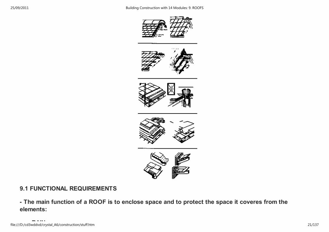
9.1 FUNCTIONAL REQUIREMENTS
- The main function of a ROOF is to enclose space and to protect the space it coveres from the
elements:
RAIN
25/09/2011 Building Construction with 14 Modules: 9. ROOFS
file:///D:/cd3wddvd/crystal_A6/construction/stuff.htm 21/137
RAIN
WIND
HEAT
- To fulfil its functions efficiently the roof normally must satisfy the same requirements as the walls:
STRENGTH and STABILITY
WEATHER RESISTANCE
THERMAL INSULATION
FIRE RESISTANCE
SOUND INSULATION
9.1.1 STRENGTH AND STABILITY
STRENGTH AND STABILITY are provided by the roof structure and a major consideration in the design
and choice of the structure is that of a SPAN.
The wide variety of roof types in different materials which have been developed is - in main - the result of
the search for the most economic means of carrying; the roof structure and its load over spans of
varying degrees.
In all types of structures it is necessary to keep the DEAD WEIGHT to a minimum, so that the imposed
loads can be carried with the greatest economy of materials.
The degree of efficiency - in this respect - is indicated by the DEAD/LITE LOAD RATIO, expressed in the
terms of Loads per square metre of area covered or per metre run of roof structure
The structural problem in the design of WIDE SPAN ROOF STRUCTURES is - therefore - primarily that of
achieving a DEAD/LIVE LOAD RATIO as low as possible.
25/09/2011 Building Construction with 14 Modules: 9. ROOFS
file:///D:/cd3wddvd/crystal_A6/construction/stuff.htm 22/137
achieving a DEAD/LIVE LOAD RATIO as low as possible.
In solving this problem, two factors are important:
1) The characteristics of the materials to be used,
2) The form or shape of the roof
- if materials are STRONG less material is required to resist given forces.
- if materials are STIFF, they will deform little under load and the structure may be of minimum
depth
- if materials are LIGHT, the self - weight of the structure will be small.
ALL OF THESE CONTRIBUTE TO A STRUCTURE OF SMALL DEAD WEIG
In addition to the dead load and the superimposed loads, the roof must resist the EFFECTS OF "WIND.
25/09/2011 Building Construction with 14 Modules: 9. ROOFS
file:///D:/cd3wddvd/crystal_A6/construction/stuff.htm 23/137
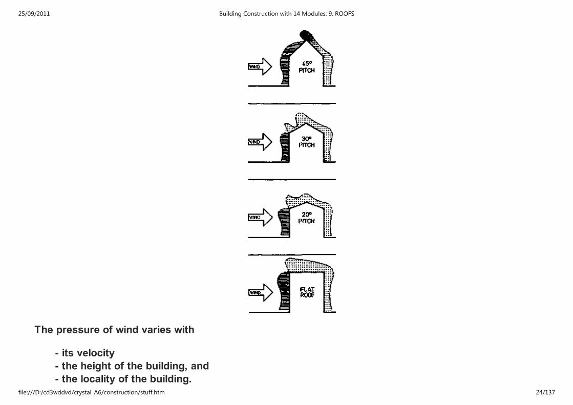
The pressure of wind varies with
- its velocity
- the height of the building, and
- the locality of the building.
25/09/2011 Building Construction with 14 Modules: 9. ROOFS
file:///D:/cd3wddvd/crystal_A6/construction/stuff.htm 24/137
Wind may exert COMPRESSION on some parts of the roof and SUCTION on others, both in varying
degrees at different points according to the pitch of the roof.
Higher suctions and compressions occure
- at the edges of the roof
- on flat roofs and
- on low pitched roofs the suction over the windward side can be considerable.
LIGHT ROOF COVERINGS: (alu-, g.c.i.-, asbestos sheets) The supporting structure tends to be light and
the weight of the cladding and roof structure as a whole may not be heavy enough to withstand the uplift
of excessive suction during short periods of very high wind. Therefore proper fastenings to the
claddings and fixing of the roof structure to frames or walls are necessary to prevent them being
stripped off.
9.1.2 WEATHER RESISTANCE
WEATHER RESISTANCE is provided by the roof coverings and the nature of these will effect the form
and some details of the roof structure.
9.1.3 THERMAL INSULATION
In most buildings thermal insulation in the roof is either essential or increases the comfort
- in hot areas thermal insulation keeps the heat out of the building
- in cold areas thermal insulation prevents the building from greater heat loss.
25/09/2011 Building Construction with 14 Modules: 9. ROOFS
file:///D:/cd3wddvd/crystal_A6/construction/stuff.htm 25/137
Thermal insulation, however, is rarely a factor affecting the choice of the roof type, since the normal
methods of providing it are generally applicable to all forms of roofs.
These methods vary and involve
- flexible or
- stiff insulation materials.
in or under the roof cladding or structure or the use of self-supporting insulation materials such as
- wood wool
- compressed straw slabs
which are strong enough to act as substructure to the covering.
In the case of concrete surface structurs, light weight aggregate concrete may be used (either fully or
partly).
9.1.4 FIRE RESISTANCE
Adequate fire resistance is necessary in order to give protection against the spread of fire from and to
any adjacent buildings and to prevent early collaps of the roof.
These matters will be discussed later under the topic "Fire protection".
9.1.5 SOUND INSULATION
25/09/2011 Building Construction with 14 Modules: 9. ROOFS
file:///D:/cd3wddvd/crystal_A6/construction/stuff.htm 26/137
9.1.5 SOUND INSULATION
Host forms of roof construction provide for the majority of buildings an adequate degree of insulation
against sound from extern. Sources. Only in special cases, such as concert halls in noisy localities or
hospitals along highways with heavy traffic, precautions night be necessary and might also affect the
choice and design of the roof structure.
The fact, that weight and discontinuity of structure are important factors in sound insulating
construction, makes this problem difficult in the case of roofs.
9.2 TYPES OF ROOF STRUCTURES
- The area of the roof together with the roof coverings (which may be defined as the 'SKIN' of the roof
and which can be constructed in many different ways) are carried by the ROOF STRUCTURE
- In order to drain the rainwater properly the 'SKIN' has to be more or less inclined.
- The better the 'SKIN' of the roof is able to protect the roof structures and the space enclosed from rain
and wind, the flatter the roof can be constructed.
- The different types of roofs may be broadly classified in three ways:
according to the
1) shape of the roof
2) structure of the roof (+building materials + span)
3) coverings of the roof (+angle of inclination)
- shape, materials and colour of the 'skin' of the roof are most important for the appearance of the
building. Therefore shape, degree of inclination as well als the covering material should be in accordance
with local envirement.
25/09/2011 Building Construction with 14 Modules: 9. ROOFS
file:///D:/cd3wddvd/crystal_A6/construction/stuff.htm 27/137
with local envirement.
9.2.1 FLAT AND PITCHED ROOFS
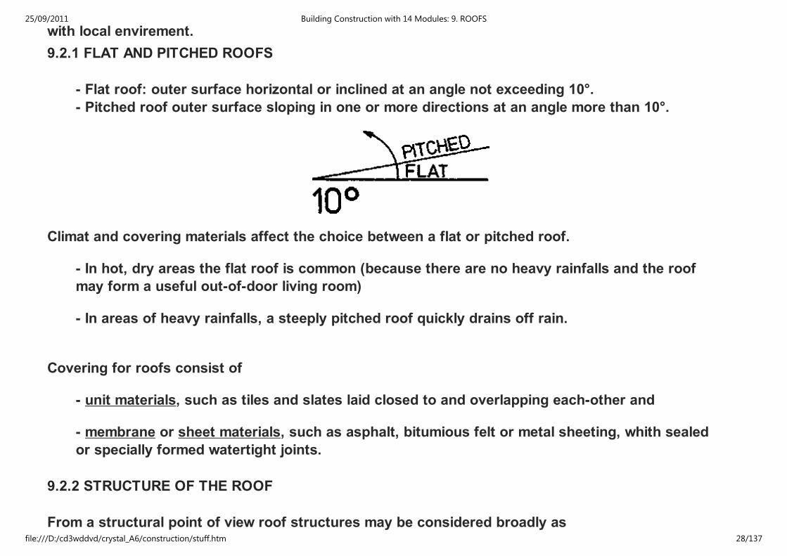
- Flat roof: outer surface horizontal or inclined at an angle not exceeding 10°.
- Pitched roof outer surface sloping in one or more directions at an angle more than 10°.
Climat and covering materials affect the choice between a flat or pitched roof.
- In hot, dry areas the flat roof is common (because there are no heavy rainfalls and the roof
may form a useful out-of-door living room)
- In areas of heavy rainfalls, a steeply pitched roof quickly drains off rain.
Covering for roofs consist of
- unit materials, such as tiles and slates laid closed to and overlapping each-other and
- membrane or sheet materials, such as asphalt, bitumious felt or metal sheeting, whith sealed
or specially formed watertight joints.
9.2.2 STRUCTURE OF THE ROOF
From a structural point of view roof structures may be considered broadly as
25/09/2011 Building Construction with 14 Modules: 9. ROOFS
file:///D:/cd3wddvd/crystal_A6/construction/stuff.htm 28/137
From a structural point of view roof structures may be considered broadly as
- two - or
- three - dimensional forms.
• Two - dimensional structures for practical purpose have LENGTH and DEPTH only and all forces are
resolved in two dimensions with in a single vertical plane (only SPANNING FUNCTION).
• Three-dimensional structures have LENGTH,DEPTH and BREADTH, and forces are resolved in three
dimensions within the structure. These forms can fulfil a COVERING and ENCLOSING FUNKTION as well
als that of SPANNING. The general term is SPACE STRUCTURES.
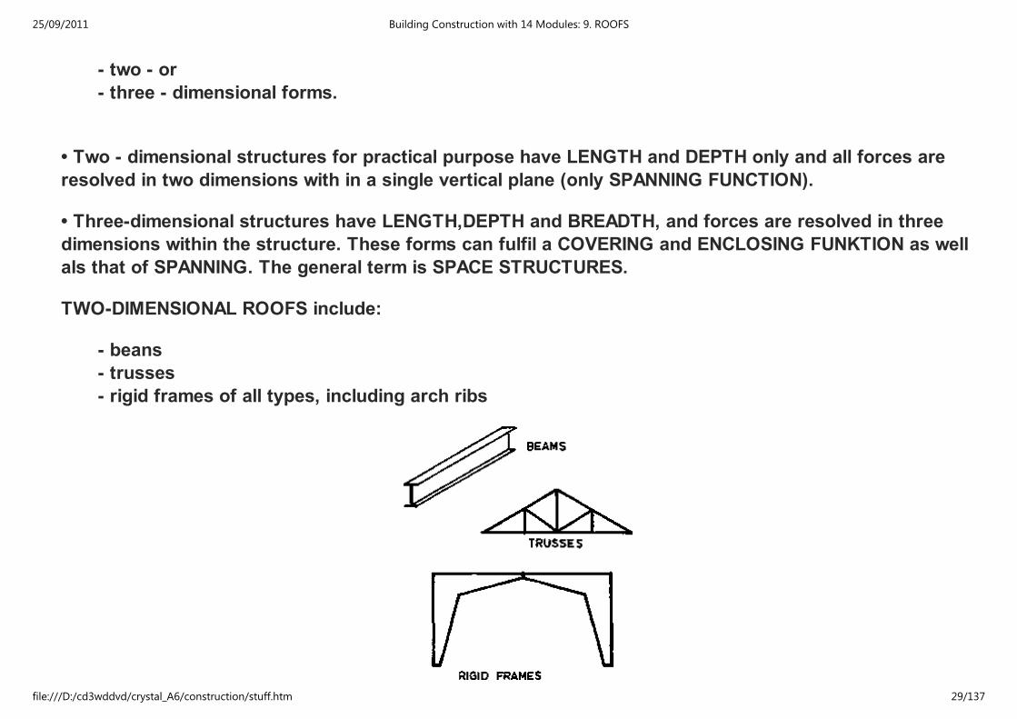
TWO-DIMENSIONAL ROOFS include:
- beans
- trusses
- rigid frames of all types, including arch ribs
25/09/2011 Building Construction with 14 Modules: 9. ROOFS
file:///D:/cd3wddvd/crystal_A6/construction/stuff.htm 29/137
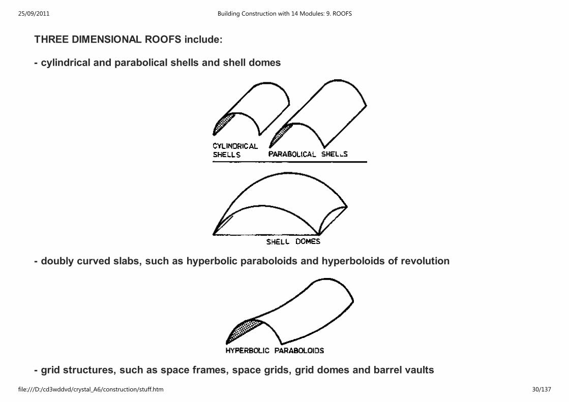
THREE DIMENSIONAL ROOFS include:
- cylindrical and parabolical shells and shell domes
- doubly curved slabs, such as hyperbolic paraboloids and hyperboloids of revolution
- grid structures, such as space frames, space grids, grid domes and barrel vaults
25/09/2011 Building Construction with 14 Modules: 9. ROOFS
file:///D:/cd3wddvd/crystal_A6/construction/stuff.htm 30/137
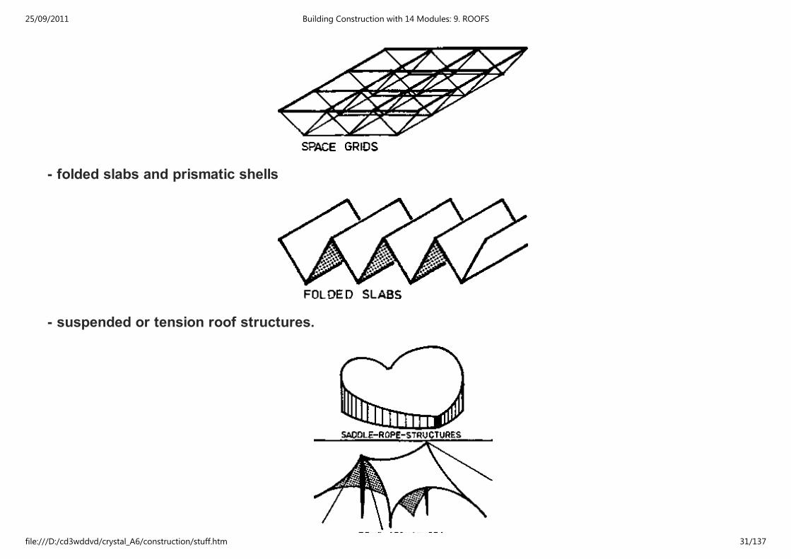
- folded slabs and prismatic shells
- suspended or tension roof structures.
25/09/2011 Building Construction with 14 Modules: 9. ROOFS
file:///D:/cd3wddvd/crystal_A6/construction/stuff.htm 31/137
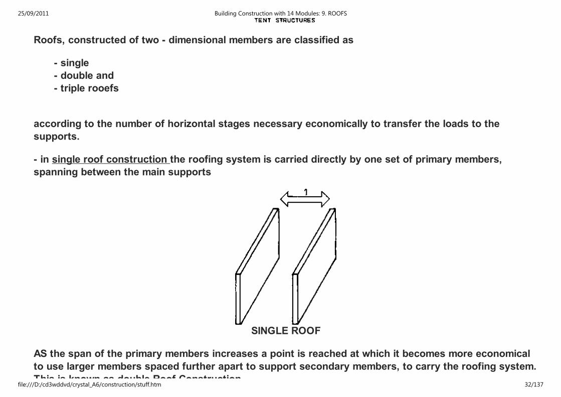
Roofs, constructed of two - dimensional members are classified as
- single
- double and
- triple rooefs
according to the number of horizontal stages necessary economically to transfer the loads to the
supports.
- in single roof construction the roofing system is carried directly by one set of primary members,
spanning between the main supports
SINGLE ROOF
AS the span of the primary members increases a point is reached at which it becomes more economical
to use larger members spaced further apart to support secondary members, to carry the roofing system.
This is known as double Roof Construction.
25/09/2011 Building Construction with 14 Modules: 9. ROOFS
file:///D:/cd3wddvd/crystal_A6/construction/stuff.htm 32/137

This is known as double Roof Construction.
DOUBLE ROOF
• In some circumstances spans are such that three sets of members are required to produce an
economic structure, resulting in three stages of support
This is called Triple Roof Construction.
• This classification is applied to both flat and pitched roofs (as well as to floor construction).
25/09/2011 Building Construction with 14 Modules: 9. ROOFS
file:///D:/cd3wddvd/crystal_A6/construction/stuff.htm 33/137
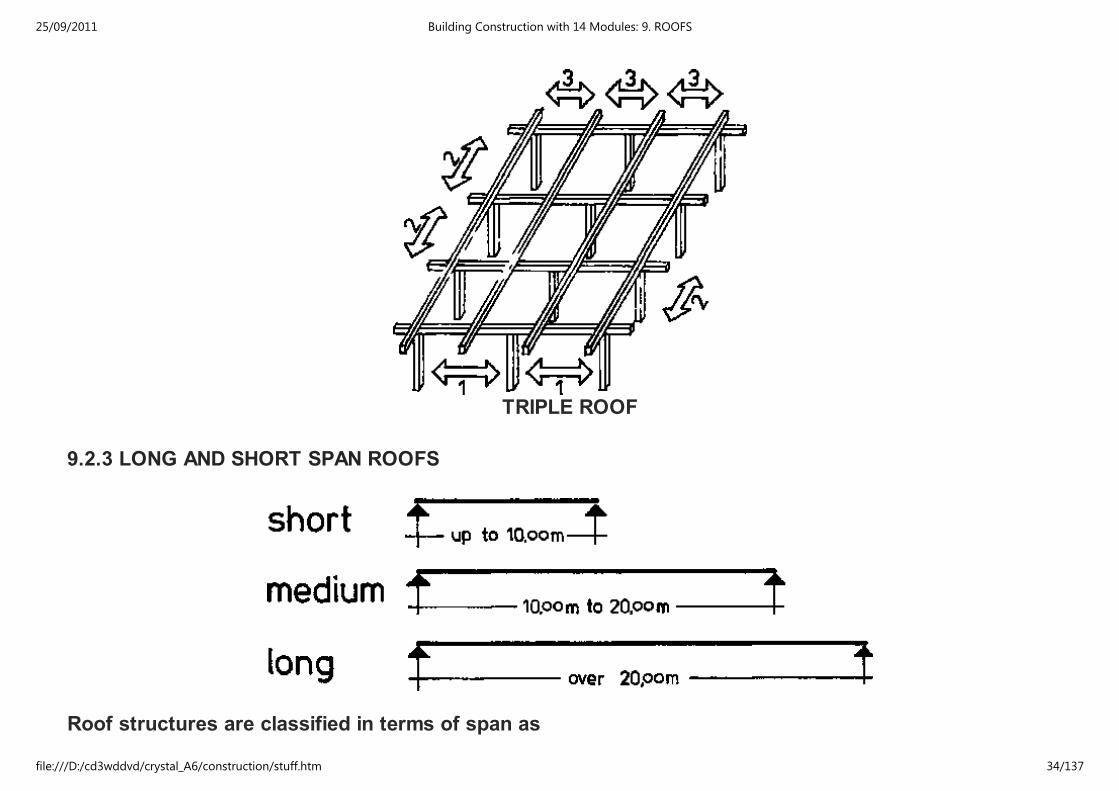
TRIPLE ROOF
9.2.3 LONG AND SHORT SPAN ROOFS
Roof structures are classified in terms of span as
25/09/2011 Building Construction with 14 Modules: 9. ROOFS
file:///D:/cd3wddvd/crystal_A6/construction/stuff.htm 34/137
- short span (up to 10.00m)
- medium span (10,00 to 20.00m)
- long span (over 20.00 m)
• Short span construction will usually be cheapest
• As an increase in the distance between supports usually results in an increase in the cost - comparible
with requirements of clear floor area should always be adopted in design.
• Three dimensional structures are normally not economic over short spans.
N.B. All types of roof structures, which are introduced in the following, refer to the SHORT SPAN
CONSTRUCTION only.
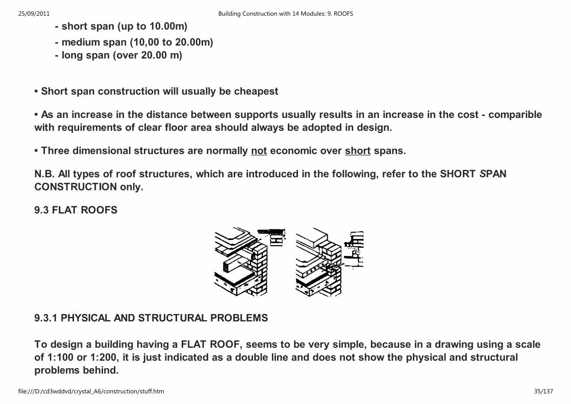
9.3 FLAT ROOFS
9.3.1 PHYSICAL AND STRUCTURAL PROBLEMS
To design a building having a FLAT ROOF, seems to be very simple, because in a drawing using a scale
of 1:100 or 1:200, it is just indicated as a double line and does not show the physical and structural
problems behind.
25/09/2011 Building Construction with 14 Modules: 9. ROOFS
file:///D:/cd3wddvd/crystal_A6/construction/stuff.htm 35/137
Plenty of flat roofs (in Arusha and all over TAN) are leaking, because of
- insufficient (or wrong) construction, and
- lack of adequate building materials (expecially for ther mal insulation and waterproof
membranes).
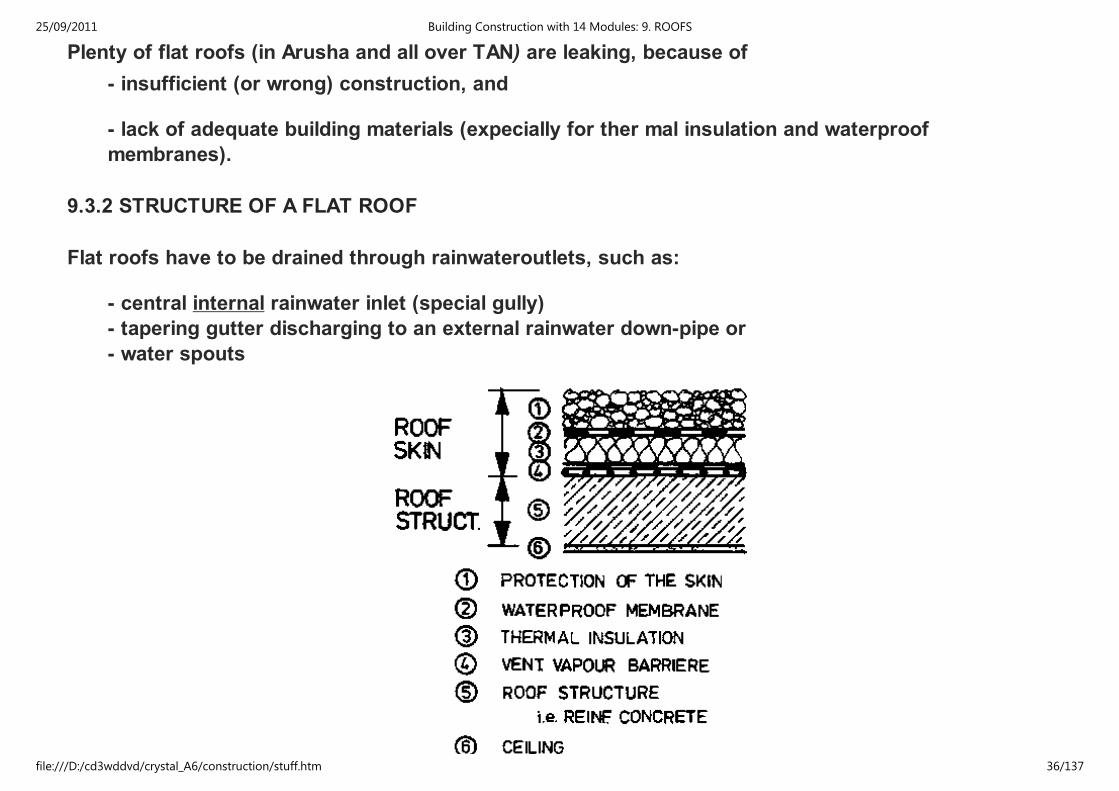
9.3.2 STRUCTURE OF A FLAT ROOF
Flat roofs have to be drained through rainwateroutlets, such as:
- central internal rainwater inlet (special gully)
- tapering gutter discharging to an external rainwater down-pipe or
- water spouts
25/09/2011 Building Construction with 14 Modules: 9. ROOFS
file:///D:/cd3wddvd/crystal_A6/construction/stuff.htm 36/137
STRUCTURE of a FLAT ROOF
9.3.3 THERMAL INSULATION MATERIAL
For most types of roofs (especially for flat roofs) thermal insulation is provided by NON-STRUCTURAL
materials of two types with:
1) Low thermal conductivity
2) high thermal reflectivity.
Materials of low thermal conductivity have a high -percentage volume of GAS or AIR VOIDS, which retard
the transmission of heat.
Most efficient are materials with a CLOSED AIR or GAS CELL STRUCTURE, such as EXPANDET
PLASTICS, used in board or granule form, a few mm thickness of which give insulation eaqual to a
substantial thickness of brickwork, dense concrete or stone.
Typical of this class of insulators are:
a) QUILTS: consisting of
- glass fibre
- rock wool or slag wool (classified as MINERAL WOOL)
b) SLABS: of
- wood wool
- straw boarded
- fibre boarded
25/09/2011 Building Construction with 14 Modules: 9. ROOFS
file:///D:/cd3wddvd/crystal_A6/construction/stuff.htm 37/137
- fibre boarded
- expanded plastics
- cork
- semi rigid glass fibre
- foamed glass
- thick, lowdensity soft wood strips (preferably 50 mm and above)
c) GRANULATED or NODULATED materials used as loose fills, in layers on ceilings or fills in cavities:
- pelleted slag wool
- exfoliated vermicolite (a naturally occuring micaceous material which, expands when its
constained water is vaporized by heat).
d) PLASTICS FOAMED in - SITU and injected into cavities to fill them. (note: The FOAM stabilizes the
insulating air in the cavity by incorporating it as millions of very small cells within the materials.)
e) AIR or GAS CELLS within a basically highdensity material, as in foamed concrete or screed.
f) LIGHTWEIGHT - AGGREGATE concrete and screeds which, to be effective, must be of ad equate
thickness, dried out and kept dry.
g) SPRAYED INSULATION, of asbestos fibre with water-activated binders, or lightweight plasters, applied
to a thickness of 12 mm or more, on exposed protected internal surfaces.
NOTE: The presence of MOISTURE in an insulation material will REDUCE its efficiency.
9.3.4 SINGLE AND DOUBLE FLAT ROOF CONSTRUCTION
25/09/2011 Building Construction with 14 Modules: 9. ROOFS
file:///D:/cd3wddvd/crystal_A6/construction/stuff.htm 38/137
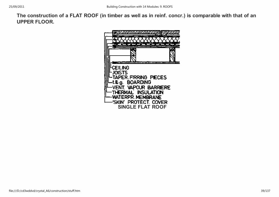
The construction of a FLAT ROOF (in timber as well as in reinf. concr.) is comparable with that of an
UPPER FLOOR.
SINGLE FLAT ROOF
25/09/2011 Building Construction with 14 Modules: 9. ROOFS
file:///D:/cd3wddvd/crystal_A6/construction/stuff.htm 39/137
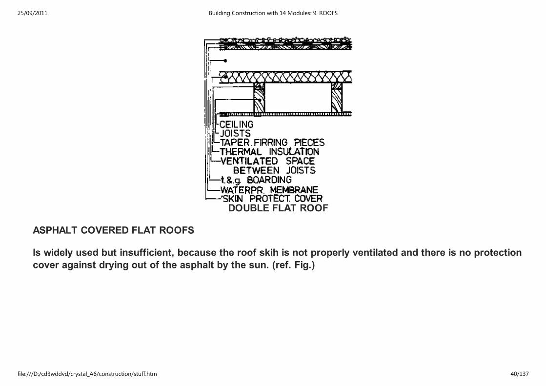
DOUBLE FLAT ROOF
ASPHALT COVERED FLAT ROOFS
Is widely used but insufficient, because the roof skih is not properly ventilated and there is no protection
cover against drying out of the asphalt by the sun. (ref. Fig.)
25/09/2011 Building Construction with 14 Modules: 9. ROOFS
file:///D:/cd3wddvd/crystal_A6/construction/stuff.htm 40/137
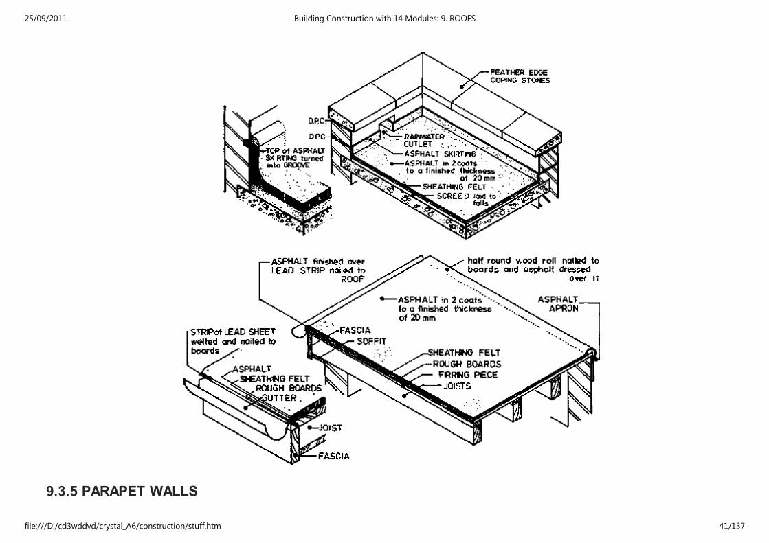
9.3.5 PARAPET WALLS
25/09/2011 Building Construction with 14 Modules: 9. ROOFS
file:///D:/cd3wddvd/crystal_A6/construction/stuff.htm 41/137
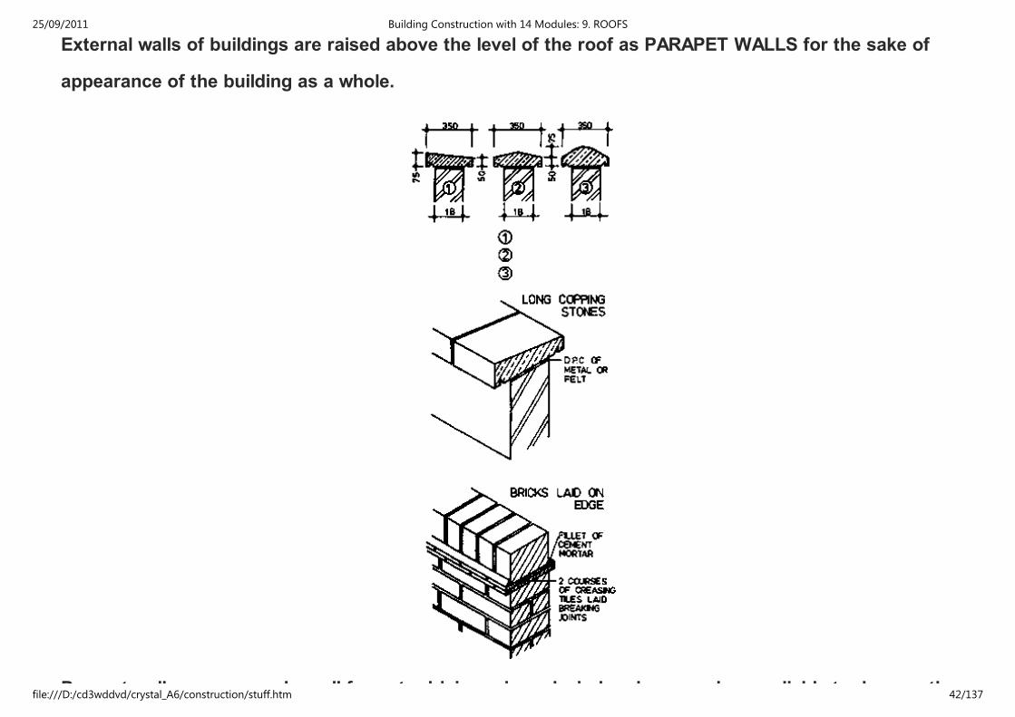
External walls of buildings are raised above the level of the roof as PARAPET WALLS for the sake of
appearance of the building as a whole.
Parapet walls are exposed on all faces to driving rain and wind and are much more liable to damage than
25/09/2011 Building Construction with 14 Modules: 9. ROOFS
file:///D:/cd3wddvd/crystal_A6/construction/stuff.htm 42/137
Parapet walls are exposed on all faces to driving rain and wind and are much more liable to damage than
external walls below eaves level.
Parapet walls are not weighted down by floors and roofs and it is generally accepted that they should
not be built above roof level higher than six times the least thickness of the parapet wall.
Parapet walls to be covered or capped with some non-absorbent material such as:
- natural stone (protective and decorative)
- artificial stone: Stones are made with a core of concrete faced with a mixture of crushed stone
particles and cement.
- brick capping: bricks are laid - on - edge on top of two coarses of creasing tiles laid-breaking
joint-in cement mortar.
- D.P.G. beneath coping stones within the Parapet walls.
9.4 PITCHED ROOFS
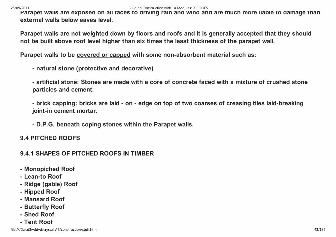
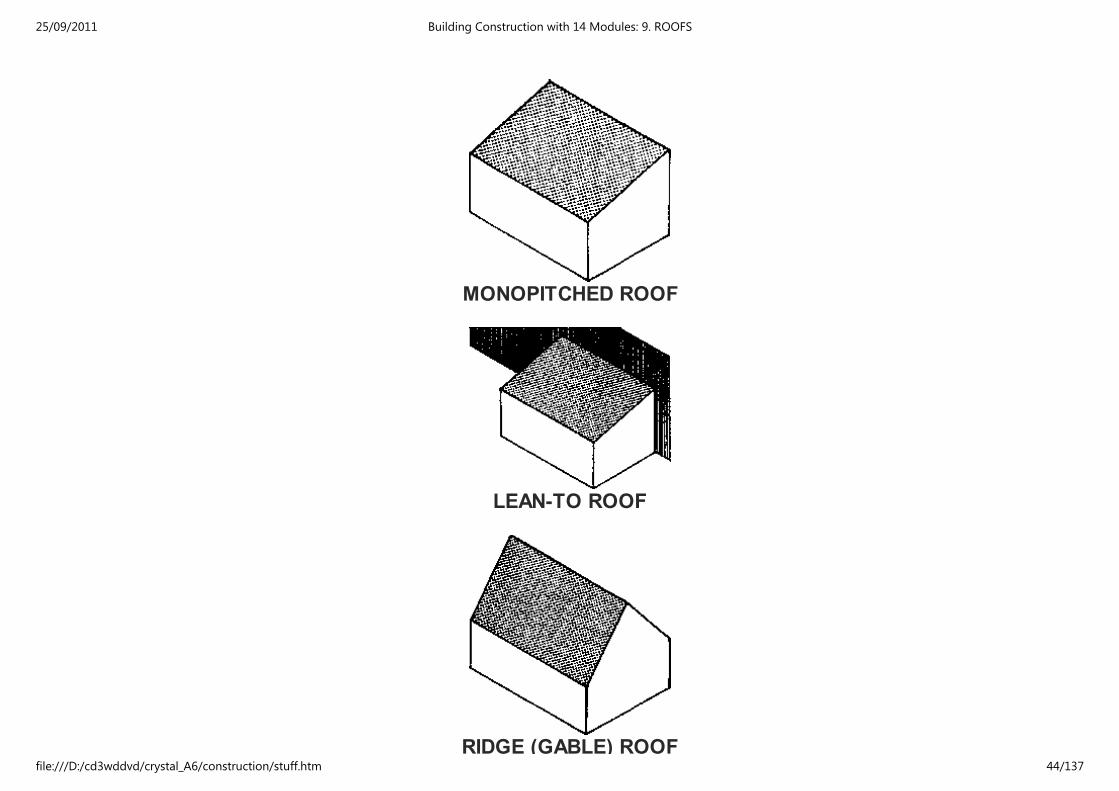
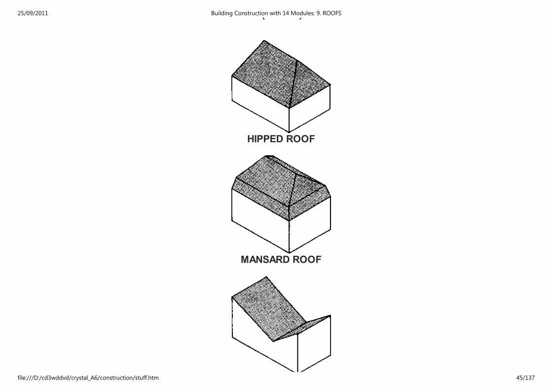
9.4.1 SHAPES OF PITCHED ROOFS IN TIMBER
- Monopiched Roof
- Lean-to Roof
- Ridge (gable) Roof
- Hipped Roof
- Mansard Roof
- Butterfly Roof
- Shed Roof
- Tent Roof
25/09/2011 Building Construction with 14 Modules: 9. ROOFS
file:///D:/cd3wddvd/crystal_A6/construction/stuff.htm 43/137
MONOPITCHED ROOF
LEAN-TO ROOF
RIDGE (GABLE) ROOF
25/09/2011 Building Construction with 14 Modules: 9. ROOFS
file:///D:/cd3wddvd/crystal_A6/construction/stuff.htm 44/137
RIDGE (GABLE) ROOF
HIPPED ROOF
MANSARD ROOF
25/09/2011 Building Construction with 14 Modules: 9. ROOFS
file:///D:/cd3wddvd/crystal_A6/construction/stuff.htm 45/137
BUTTERFLY ROOF
SHED ROOF
TENT ROOF
9.4.2 TERMS
25/09/2011 Building Construction with 14 Modules: 9. ROOFS
file:///D:/cd3wddvd/crystal_A6/construction/stuff.htm 46/137
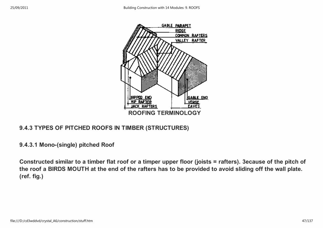
ROOFING TERMINOLOGY
9.4.3 TYPES OF PITCHED ROOFS IN TIMBER (STRUCTURES)
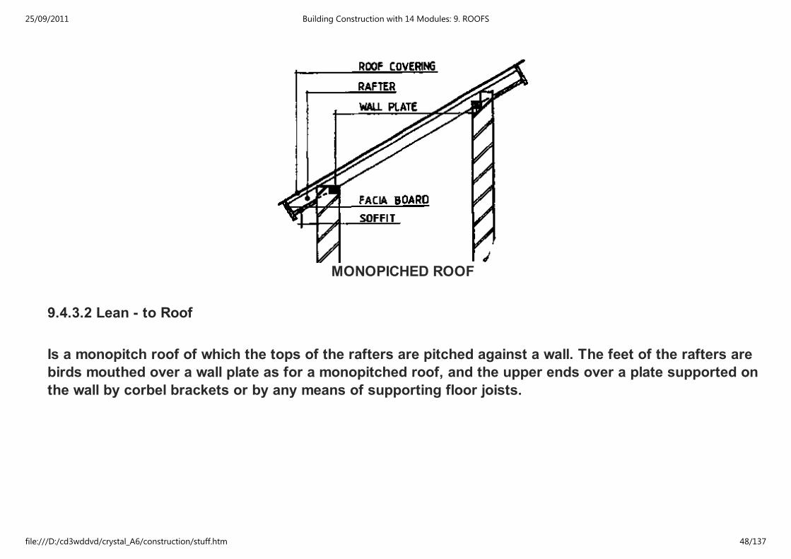
9.4.3.1 Mono-(single) pitched Roof
Constructed similar to a timber flat roof or a timper upper floor (joists = rafters). 3ecause of the pitch of
the roof a BIRDS MOUTH at the end of the rafters has to be provided to avoid sliding off the wall plate.
(ref. fig.)
25/09/2011 Building Construction with 14 Modules: 9. ROOFS
file:///D:/cd3wddvd/crystal_A6/construction/stuff.htm 47/137
MONOPICHED ROOF
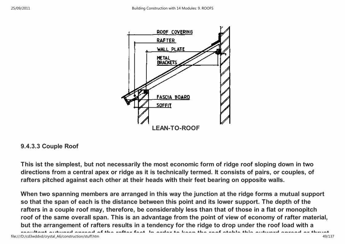
9.4.3.2 Lean - to Roof
Is a monopitch roof of which the tops of the rafters are pitched against a wall. The feet of the rafters are
birds mouthed over a wall plate as for a monopitched roof, and the upper ends over a plate supported on
the wall by corbel brackets or by any means of supporting floor joists.
25/09/2011 Building Construction with 14 Modules: 9. ROOFS
file:///D:/cd3wddvd/crystal_A6/construction/stuff.htm 48/137
LEAN-TO-ROOF
9.4.3.3 Couple Roof
This ist the simplest, but not necessarily the most economic form of ridge roof sloping down in two
directions from a central apex or ridge as it is technically termed. It consists of pairs, or couples, of
rafters pitched against each other at their heads with their feet bearing on opposite walls.
When two spanning members are arranged in this way the junction at the ridge forms a mutual support
so that the span of each is the distance between this point and its lower support. The depth of the
rafters in a couple roof may, therefore, be considerably less than that of those in a flat or monopitch
roof of the same overall span. This is an advantage from the point of view of economy of rafter material,
but the arrangement of rafters results in a tendency for the ridge to drop under the roof load with a
resultant outward spread of the rafter feet. In order to keep the roof stable this outward spread or thrust
25/09/2011 Building Construction with 14 Modules: 9. ROOFS
file:///D:/cd3wddvd/crystal_A6/construction/stuff.htm 49/137
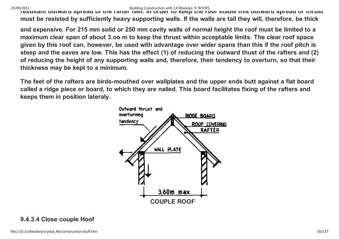
resultant outward spread of the rafter feet. In order to keep the roof stable this outward spread or thrust
must be resisted by sufficiently heavy supporting walls. If the walls are tall they will, therefore, be thick
and expensive. For 215 mm solid or 250 mm cavity walls of normal height the roof must be limited to a
maximum clear span of about 3.oo m to keep the thrust within acceptable limits. The clear roof space
given by this roof can, however, be used with advantage over wider spans than this if the roof pitch is
steep and the eaves are low. This has the effect (1) of reducing the outward thust of the rafters and (2)
of reducing the height of any supporting walls and, therefore, their tendency to overturn, so that their
thickness may be kept to a minimum.
The feet of the rafters are birds-mouthed over wallplates and the upper ends butt against a flat board
called a ridge piece or board, to which they are nailed. This board facilitates fixing of the rafters and
keeps them in position lateraly.
COUPLE ROOF
9.4.3.4 Close couple Hoof
25/09/2011 Building Construction with 14 Modules: 9. ROOFS
file:///D:/cd3wddvd/crystal_A6/construction/stuff.htm 50/137
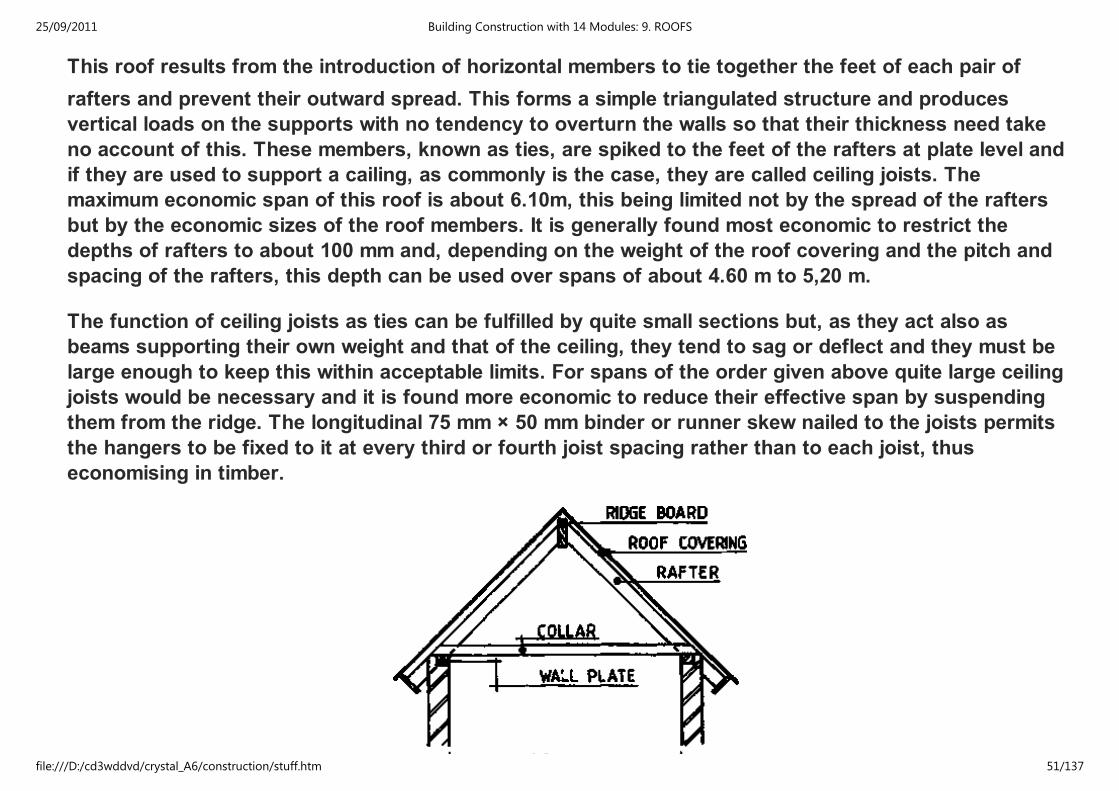
This roof results from the introduction of horizontal members to tie together the feet of each pair of
rafters and prevent their outward spread. This forms a simple triangulated structure and produces
vertical loads on the supports with no tendency to overturn the walls so that their thickness need take
no account of this. These members, known as ties, are spiked to the feet of the rafters at plate level and
if they are used to support a cailing, as commonly is the case, they are called ceiling joists. The
maximum economic span of this roof is about 6.10m, this being limited not by the spread of the rafters
but by the economic sizes of the roof members. It is generally found most economic to restrict the
depths of rafters to about 100 mm and, depending on the weight of the roof covering and the pitch and
spacing of the rafters, this depth can be used over spans of about 4.60 m to 5,20 m.
The function of ceiling joists as ties can be fulfilled by quite small sections but, as they act also as
beams supporting their own weight and that of the ceiling, they tend to sag or deflect and they must be
large enough to keep this within acceptable limits. For spans of the order given above quite large ceiling
joists would be necessary and it is found more economic to reduce their effective span by suspending
them from the ridge. The longitudinal 75 mm × 50 mm binder or runner skew nailed to the joists permits
the hangers to be fixed to it at every third or fourth joist spacing rather than to each joist, thus
economising in timber.
25/09/2011 Building Construction with 14 Modules: 9. ROOFS
file:///D:/cd3wddvd/crystal_A6/construction/stuff.htm 51/137
CLOSE COUPLE ROOF
Fixing of hangers to runners should be deferred until the roof covering has been laid in order to avoid
deflection of the ceiling joists due to the transfer through the hangers of any slight movement of the roof
structure as it takes up the load.
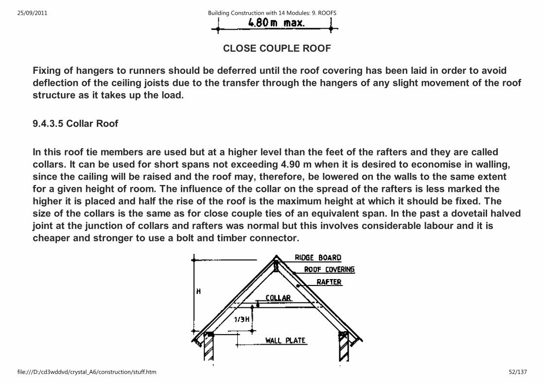
9.4.3.5 Collar Roof
In this roof tie members are used but at a higher level than the feet of the rafters and they are called
collars. It can be used for short spans not exceeding 4.90 m when it is desired to economise in walling,
since the cailing will be raised and the roof may, therefore, be lowered on the walls to the same extent
for a given height of room. The influence of the collar on the spread of the rafters is less marked the
higher it is placed and half the rise of the roof is the maximum height at which it should be fixed. The
size of the collars is the same as for close couple ties of an equivalent span. In the past a dovetail halved
joint at the junction of collars and rafters was normal but this involves considerable labour and it is
cheaper and stronger to use a bolt and timber connector.
25/09/2011 Building Construction with 14 Modules: 9. ROOFS
file:///D:/cd3wddvd/crystal_A6/construction/stuff.htm 52/137
COLLAR ROOF
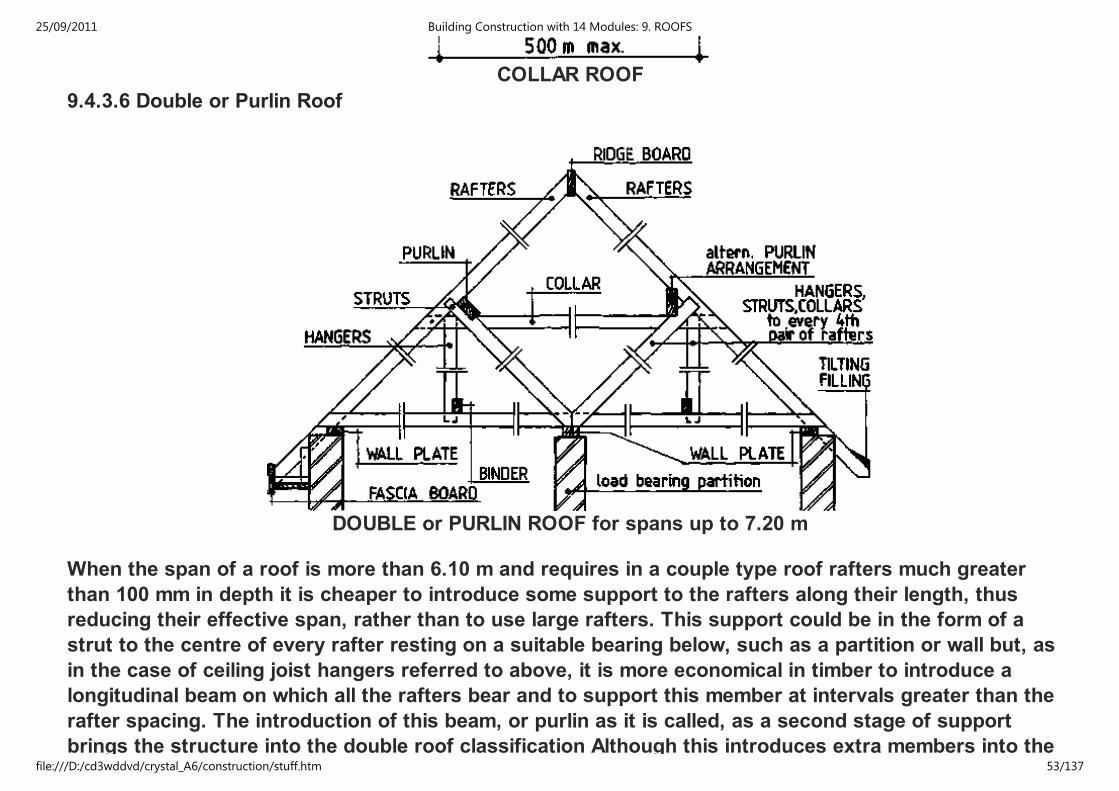
9.4.3.6 Double or Purlin Roof
DOUBLE or PURLIN ROOF for spans up to 7.20 m
When the span of a roof is more than 6.10 m and requires in a couple type roof rafters much greater
than 100 mm in depth it is cheaper to introduce some support to the rafters along their length, thus
reducing their effective span, rather than to use large rafters. This support could be in the form of a
strut to the centre of every rafter resting on a suitable bearing below, such as a partition or wall but, as
in the case of ceiling joist hangers referred to above, it is more economical in timber to introduce a
longitudinal beam on which all the rafters bear and to support this member at intervals greater than the
rafter spacing. The introduction of this beam, or purlin as it is called, as a second stage of support
brings the structure into the double roof classification Although this introduces extra members into the
25/09/2011 Building Construction with 14 Modules: 9. ROOFS
file:///D:/cd3wddvd/crystal_A6/construction/stuff.htm 53/137
brings the structure into the double roof classification Although this introduces extra members into the
construction the total cube of timber in the roof (and the weight of the roof) rises less with increase in
span than if the rafters were increased in size.
The purlins may be supported directly by cross walls or partitions at sufficiently close spacing along the
length of the purlins or by struts off any suitably placed walls partitions or chimneys. The size of the
purlins will be governed by the weight of the roofing system, the spacing of the purlins (if the length of
rafter supported) and their span. As with rafters an increase in span results in increased size and cost of
purlins and the span should, therefore, be kept within economic limits. Depending on the combination of
weight and rafter length a 225 mm × 75 mm purlin will span from about 2.50 m to 3.70 m. If the spacing of
available supports is such that purlins much larger than this are required it may be better to select an
alternative method of construction.
Purlins may be placed vertically or normal to the rafters. The former ist preferable when the purlin
bearing is directly on walls or on vertical struts, the latter is sometimes more convenient when inclined
struts are used, which is the case when supports do not occur immediately under the purlins. Where
possible inclined struts should be paired so that those to opposite purlins meet at the same point and
bear against each other over the support. If this should result in struts at an excessively low angle a
spreader piece nailed to the top of a ceiling joist may be used to increase the angle of the struts.
25/09/2011 Building Construction with 14 Modules: 9. ROOFS
file:///D:/cd3wddvd/crystal_A6/construction/stuff.htm 54/137

PURLIN ROOF
25/09/2011 Building Construction with 14 Modules: 9. ROOFS
file:///D:/cd3wddvd/crystal_A6/construction/stuff.htm 55/137
PURLIN ROOF
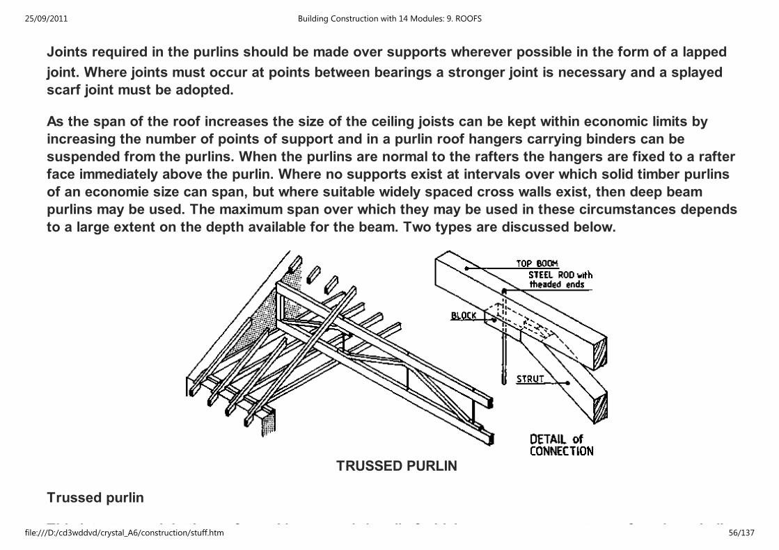
Joints required in the purlins should be made over supports wherever possible in the form of a lapped
joint. Where joints must occur at points between bearings a stronger joint is necessary and a splayed
scarf joint must be adopted.
As the span of the roof increases the size of the ceiling joists can be kept within economic limits by
increasing the number of points of support and in a purlin roof hangers carrying binders can be
suspended from the purlins. When the purlins are normal to the rafters the hangers are fixed to a rafter
face immediately above the purlin. Where no supports exist at intervals over which solid timber purlins
of an economie size can span, but where suitable widely spaced cross walls exist, then deep beam
purlins may be used. The maximum span over which they may be used in these circumstances depends
to a large extent on the depth available for the beam. Two types are discussed below.
TRUSSED PURLIN
Trussed purlin
This ist a trussed, lattice or framed beam or girder all of which. are synonymous terms for a bean built
25/09/2011 Building Construction with 14 Modules: 9. ROOFS
file:///D:/cd3wddvd/crystal_A6/construction/stuff.htm 56/137

This ist a trussed, lattice or framed beam or girder all of which. are synonymous terms for a bean built
up of triangulated members. For a given load and span as the depth of a beam increases the bending
stresses at top and bottom decrease and less material is required in the beam. This economy of material
can be developed further by concentrating the majority of the material in the beam at the top and bottom
where bending stresses are at a maximum. In the trussed beam structural depth is obtained with a
minimum of material at the centre or web by means of relatively thin triangulating members which
connect the top and bottom flanges or booms. For maximum economy bending stresses in the members
should be avoided as far as possible
To this end the members should be arranged on the 'centre line' principle as far as is practicable that is
to say at each Junction of members their centre lines should intersect at one point. For the same reason
loads should be applied only at the node points With trussed purlins however, the rafters are closely
spaced along the top boom and do not all bear at a node point; some bending therefore occurs and the
boom size must take account of this.
Purlin beam
The alternative to a trussed purlin is the thinwebbed timber beam, which may be specially fabricated or
of which there are a number of mass-produced types on the market. This consists of a plywood web
rebatted into and glued to top and bottom booms or glued at top and bottom between two timbers to
form the boons. In deep beams of this type some stiffening against buckling of the thin web is required
in the form of vertical stiffeners glued at intervals on each side of the web. In one proprietory beam this
stiffening is obtained by using a vertically corrugated ply web instead of applied stiffeners.
25/09/2011 Building Construction with 14 Modules: 9. ROOFS
file:///D:/cd3wddvd/crystal_A6/construction/stuff.htm 57/137
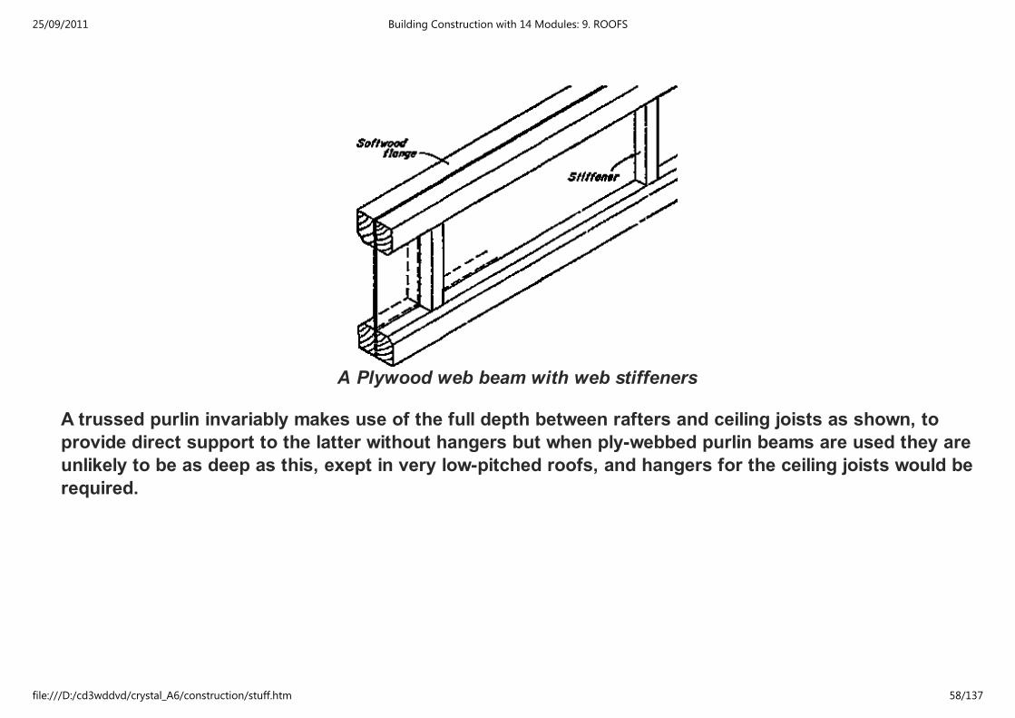
A Plywood web beam with web stiffeners
A trussed purlin invariably makes use of the full depth between rafters and ceiling joists as shown, to
provide direct support to the latter without hangers but when ply-webbed purlin beams are used they are
unlikely to be as deep as this, exept in very low-pitched roofs, and hangers for the ceiling joists would be
required.
25/09/2011 Building Construction with 14 Modules: 9. ROOFS
file:///D:/cd3wddvd/crystal_A6/construction/stuff.htm 58/137
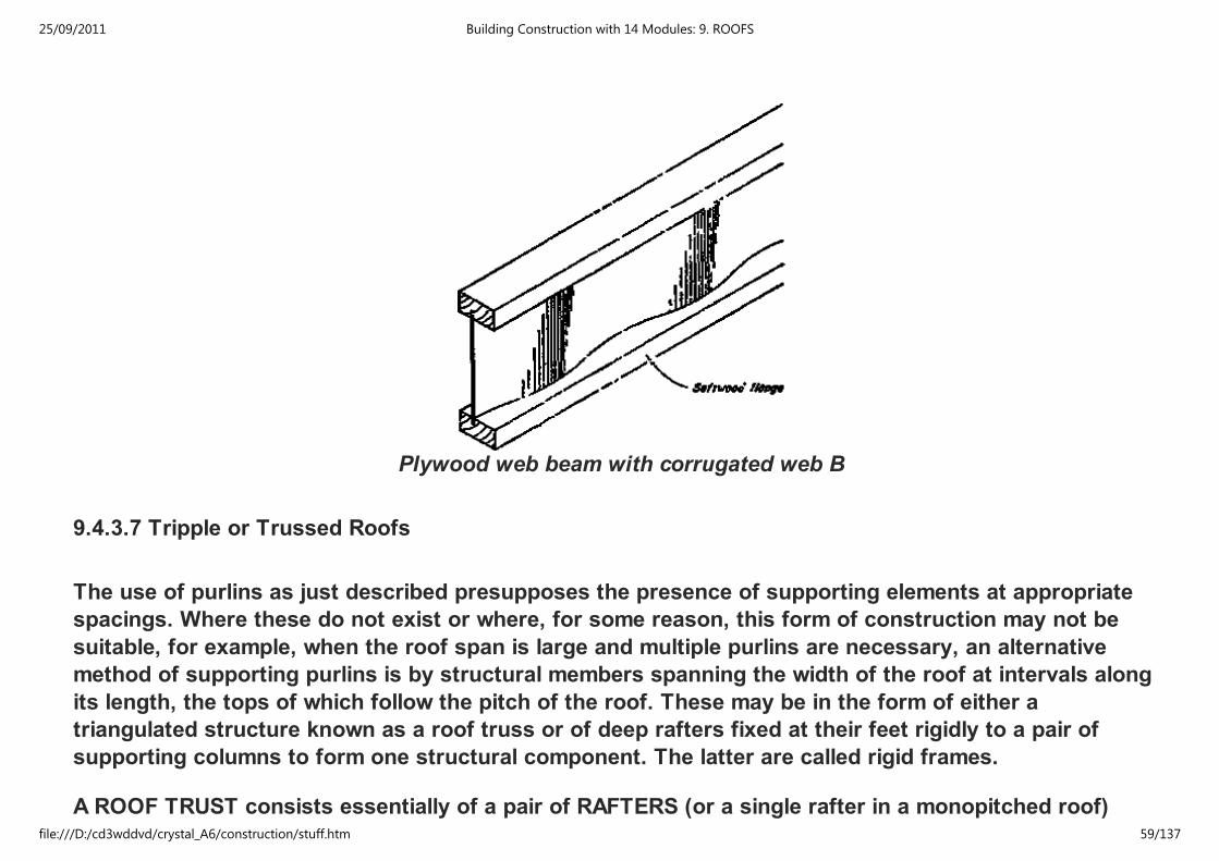
Plywood web beam with corrugated web B
9.4.3.7 Tripple or Trussed Roofs
The use of purlins as just described presupposes the presence of supporting elements at appropriate
spacings. Where these do not exist or where, for some reason, this form of construction may not be
suitable, for example, when the roof span is large and multiple purlins are necessary, an alternative
method of supporting purlins is by structural members spanning the width of the roof at intervals along
its length, the tops of which follow the pitch of the roof. These may be in the form of either a
triangulated structure known as a roof truss or of deep rafters fixed at their feet rigidly to a pair of
supporting columns to form one structural component. The latter are called rigid frames.
A ROOF TRUST consists essentially of a pair of RAFTERS (or a single rafter in a monopitched roof)
25/09/2011 Building Construction with 14 Modules: 9. ROOFS
file:///D:/cd3wddvd/crystal_A6/construction/stuff.htm 59/137
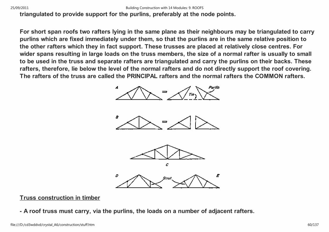
triangulated to provide support for the purlins, preferably at the node points.
For short span roofs two rafters lying in the same plane as their neighbours may be triangulated to carry
purlins which are fixed immediately under them, so that the purlins are in the same relative position to
the other rafters which they in fact support. These trusses are placed at relatively close centres. For
wider spans resulting in large loads on the truss members, the size of a normal rafter is usually to small
to be used in the truss and separate rafters are triangulated and carry the purlins on their backs. These
rafters, therefore, lie below the level of the normal rafters and do not directly support the roof covering.
The rafters of the truss are called the PRINCIPAL rafters and the normal rafters the COMMON rafters.
Truss construction in timber
- A roof truss must carry, via the purlins, the loads on a number of adjacent rafters.
- The forces on the Joints between its members are, there fore, greater than those on the joints in a
25/09/2011 Building Construction with 14 Modules: 9. ROOFS
file:///D:/cd3wddvd/crystal_A6/construction/stuff.htm 60/137
- The forces on the Joints between its members are, there fore, greater than those on the joints in a
single or double roof structure and the use of one or two nails commonly used to secure members in the
latter is insufficient in a truss.
- The detailed construction of a truss depends largely on the method adopted for joining the parts.
- Earlier methods involving mortice and tenon joints, necessitated relatively large amounts of timber at
the junctions and, therefore, large heavy members
(often larger than justified by the stresses in them) and the incorporation of large metal straps
particularly at the tension points since the mortice and tenon joint is efficient only in compression.
- This type of truss is exemplified by the traditional king post and queen-post trusses which, for these
reasons, are now absolete.
- There are three modern methodes of joining the members:
1. nailed joints
2. bolt and connector joints
3. glued joints and some times a combination of two.
- These methods require the members to be laid one against the other, or LAPPED as it is termed, to
make the joint or - alternatively - require the use of cover plates, or GUSSETS, when the members butt
one against the other.
- If two members lap, the joint is called SINGLE LAP JOINT If one member lappes by two other members,
it is called a DOUBLE LAP JOINT (also known as SANDWITCH CONSTRUCTION).
- In a single lap joint the joint is under eccentric loading. For small span trusses carrying light loads this
25/09/2011 Building Construction with 14 Modules: 9. ROOFS
file:///D:/cd3wddvd/crystal_A6/construction/stuff.htm 61/137
- In a single lap joint the joint is under eccentric loading. For small span trusses carrying light loads this
is not significant but when the joints carry large loads eccentricity should be avoided by the use of
double lap joints. Double members are also used in order to obtain a satisfactory arrangement of
members in the truss as a whole for jointing purposes.
(1) NAILED TRUSSES:
Jointing by nails is the least efficient of the three methods - but a traditional and simple method.
By preboring nail holes and using wide, thin members to provide ample fixing area, efficient structures
may be obtained, particularly where light - weight roof coverings are used.
The arrangement of nails to be calculated.
An example of the application of nailing in this manner is shown in the figure, where sandwich
construction is used to carry corrugated asbestos cement sheeting over spans up to 6.10 m. The
principal rafters and horizontal tie are each formed by two boards, 32 mm thick, and the struts and
secondary ties are 100 mm × 50 mm seantlings sandwiched between, the joints at these points being
made by direct nailing between the members. As the rafter und tie members lie in the same plane and
butt against each other at the feet of the truss it is necessary to use gussets to effect a joint at there
points. The gussets here are formed by 25 mm boards on each side set normal to the rafters and
securely nailed to each member. The extension of the gusset by two vertical boards increases the
rigidity of the whole truss. The double members at the feet are blocked apart by 50 mm pakking pieces
and at the ridge the rafters are secured to each other by a 25 mm board on each side.
25/09/2011 Building Construction with 14 Modules: 9. ROOFS
file:///D:/cd3wddvd/crystal_A6/construction/stuff.htm 62/137
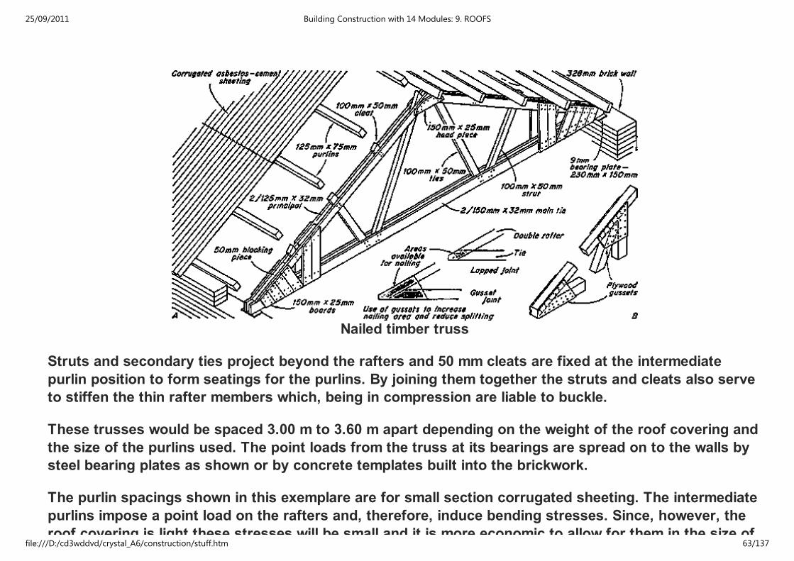
Nailed timber truss
Struts and secondary ties project beyond the rafters and 50 mm cleats are fixed at the intermediate
purlin position to form seatings for the purlins. By joining them together the struts and cleats also serve
to stiffen the thin rafter members which, being in compression are liable to buckle.
These trusses would be spaced 3.00 m to 3.60 m apart depending on the weight of the roof covering and
the size of the purlins used. The point loads from the truss at its bearings are spread on to the walls by
steel bearing plates as shown or by concrete templates built into the brickwork.
The purlin spacings shown in this exemplare are for small section corrugated sheeting. The intermediate
purlins impose a point load on the rafters and, therefore, induce bending stresses. Since, however, the
roof covering is light these stresses will be small and it is more economic to allow for them in the size of
25/09/2011 Building Construction with 14 Modules: 9. ROOFS
file:///D:/cd3wddvd/crystal_A6/construction/stuff.htm 63/137

roof covering is light these stresses will be small and it is more economic to allow for them in the size of
the rafters rather than to form nodes at these points by extra bracing members.
When self-supporting coverings such as these sheets are used they are laid directly on the purlins as in
this example, but when the roofing requires a base such as battens, boarding or other roof decking
needing support at closer intervals it is then cheaper to support the base on common rafters at the
required spacings carried in the traditional way on purlins at the node positions only. This usually
results in less timber content than if the purlins are placed at very close intervals.
When loading and span conditions require thicker members and where lapped joints do not provide
sufficient nailing area, single thickness construction with gussets throughout may be used. By this
means larger areas are available for nailing and all joints may be laid out on the 'centre line' principle.
(2) BOLTED AND CONNECTORED TRUSSES
Timber connectors are metal rings or toothed plates used to increase the efficiency of bolted joints.
They are embedded half in each of the adjecent members and transmit load from one to the other. There
are many different types, of which the most commonly used for light structures is the toothed plate
connector, a mild steel plate cut and stamped to form triangular teeth projecting on each side which
embed in the surfaces of the members on tightening the bolt which passes through the joint. For greater
loads split ring connectors are used, but these require accurately cut grooves to be formed in each
piece of timber.
Jointing by connectors and bolts permits thicker timber to be used and its application is illustrated in the
figure. This truss is for a span of 7.60 m and is designed to be spaced at 3.90 m centres and to carry
large section corrugated asbestos cement sheeting, which is self-supporting over a span of 1.40 m and a
ceiling.
Rafters and horizontal tie are of double members with single member secondary ties sandwiched
between. Struts are of double members placed on the outside of rafters and tie. This arrangement
25/09/2011 Building Construction with 14 Modules: 9. ROOFS
file:///D:/cd3wddvd/crystal_A6/construction/stuff.htm 64/137
between. Struts are of double members placed on the outside of rafters and tie. This arrangement
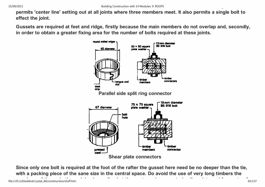
permits 'center line' setting out at all joints where three members meet. It also permits a single bolt to
effect the joint.
Gussets are required at feet and ridge, firstly because the main members do not overlap and, secondly,
in order to obtain a greater fixing area for the number of bolts required at these joints.
Parallel side split ring connector
Shear plate connectors
Since only one bolt is required at the foot of the rafter the gusset here need be no deeper than the tie,
with a packing piece of the sane size in the central space. Do avoid the use of very long timbers the
members of the main tie are joined or spliced at the centre using a central splice plate and four sets of
25/09/2011 Building Construction with 14 Modules: 9. ROOFS
file:///D:/cd3wddvd/crystal_A6/construction/stuff.htm 65/137
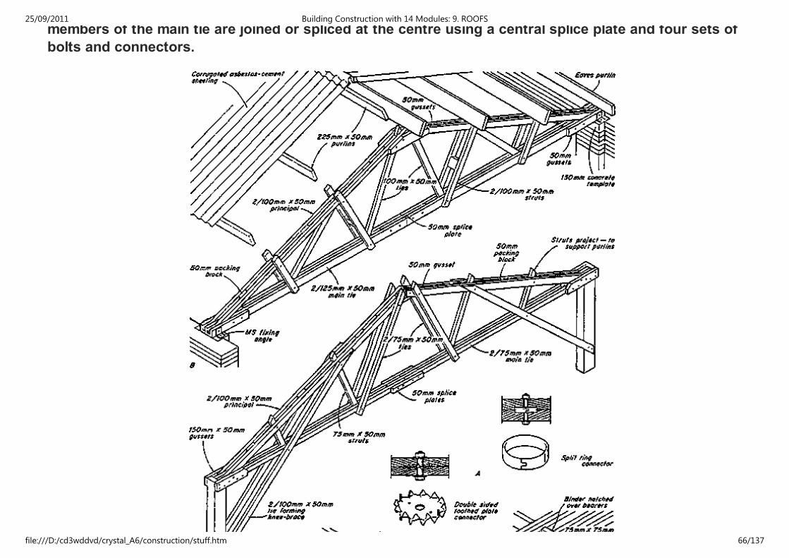
members of the main tie are joined or spliced at the centre using a central splice plate and four sets of
bolts and connectors.
25/09/2011 Building Construction with 14 Modules: 9. ROOFS
file:///D:/cd3wddvd/crystal_A6/construction/stuff.htm 66/137

Methods of suspending celling from trusses
The joints in this truss are made with, split ring connectors at each interface on 13 mm diameter bolts,
with 50 mm square washers under bolt head and nut to prevent then sinking into the wood when the
nuts are tightened. The projecting ends of struts and ties are necessary in order to obtain the minimum
end distances beyond the connectors. It will be noted that the double members in the rafters and the
long struts, which are compression members, are stiffened between the node points by 50 mm packing
blocks securely spiked in position.
A variation of this type of truss is shown. This ist designed to be supported by columns the connection
with which is stiffened against lateral movement by the triangulated and, therefore, stiff junction created
by a knee-brace joining truss and column head. This is formed by extending the lower secondary tie to
connect with the column some distance below the truss bearing thus rigidly uniting the two. In order to
obtain a satisfactory junction with the column and to provide the necessary cross-sectional area for the
knee-brace the secondary ties in this example are made of double members placed on the outside faces
of the truss, and the struts are single members. As this truss is not designed to take a ceiling load the
struts and ties are smaller, except those forming the knee-braces which must resist wind stresses. To
provide for the grater number of bolts required at the feet, due to wind loads transferred to the truss,
larger gussets are necessary at these points. A single central gusset is provided at the ridge which also
acts as a packing between the rafter members.
25/09/2011 Building Construction with 14 Modules: 9. ROOFS
file:///D:/cd3wddvd/crystal_A6/construction/stuff.htm 67/137
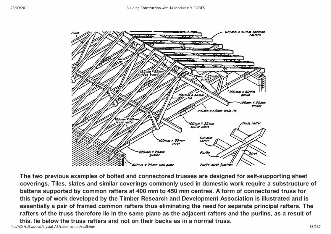
The two previous examples of bolted and connectored trusses are designed for self-supporting sheet
coverings. Tiles, slates and similar coverings commonly used in domestic work require a substructure of
battens supported by common rafters at 400 mm to 450 mm centres. A form of connectored truss for
this type of work developed by the Timber Research and Development Association is illustrated and is
essentially a pair of framed common rafters thus eliminating the need for separate principal rafters. The
rafters of the truss therefore lie in the same plane as the adjacent rafters and the purlins, as a result of
this, lie below the truss rafters and not on their backs as in a normal truss.
25/09/2011 Building Construction with 14 Modules: 9. ROOFS
file:///D:/cd3wddvd/crystal_A6/construction/stuff.htm 68/137
this, lie below the truss rafters and not on their backs as in a normal truss.
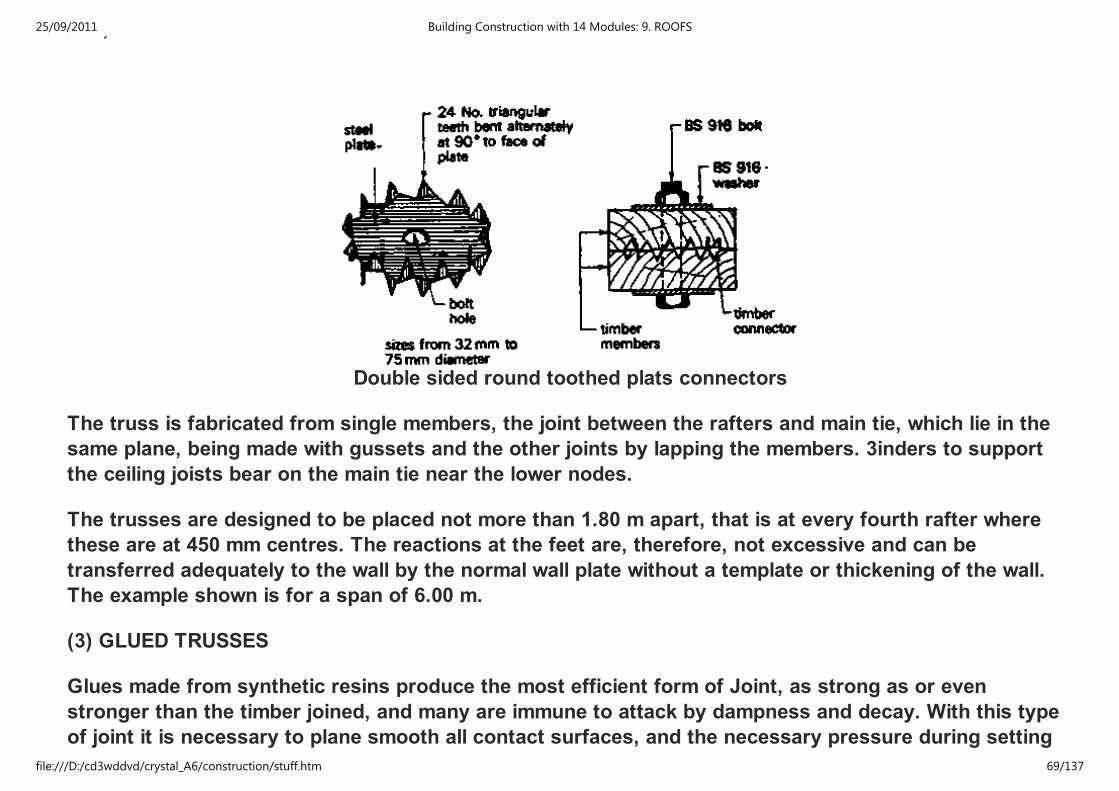
Double sided round toothed plats connectors
The truss is fabricated from single members, the joint between the rafters and main tie, which lie in the
same plane, being made with gussets and the other joints by lapping the members. 3inders to support
the ceiling joists bear on the main tie near the lower nodes.
The trusses are designed to be placed not more than 1.80 m apart, that is at every fourth rafter where
these are at 450 mm centres. The reactions at the feet are, therefore, not excessive and can be
transferred adequately to the wall by the normal wall plate without a template or thickening of the wall.
The example shown is for a span of 6.00 m.
(3) GLUED TRUSSES
Glues made from synthetic resins produce the most efficient form of Joint, as strong as or even
stronger than the timber joined, and many are immune to attack by dampness and decay. With this type
of joint it is necessary to plane smooth all contact surfaces, and the necessary pressure during setting
of the glue is provided by cramps or by bolts or nails which act as cramps. These are usually left in
25/09/2011 Building Construction with 14 Modules: 9. ROOFS
file:///D:/cd3wddvd/crystal_A6/construction/stuff.htm 69/137
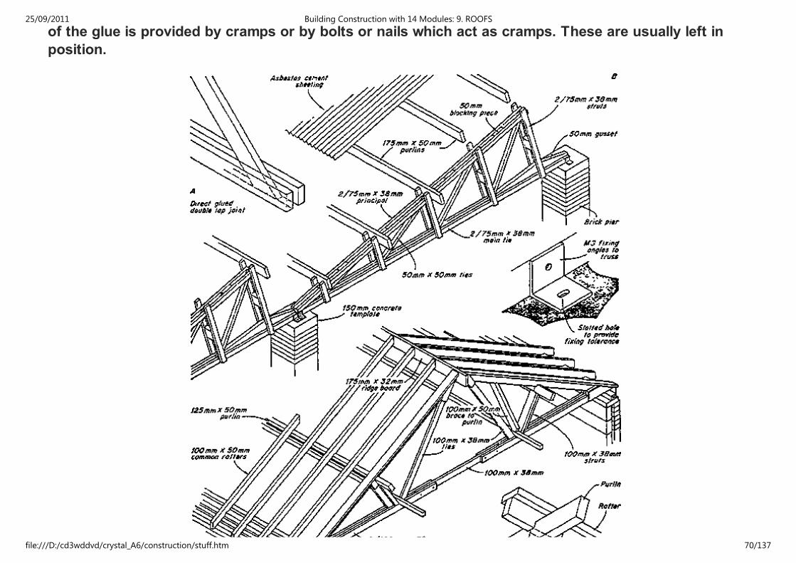
of the glue is provided by cramps or by bolts or nails which act as cramps. These are usually left in
position.
25/09/2011 Building Construction with 14 Modules: 9. ROOFS
file:///D:/cd3wddvd/crystal_A6/construction/stuff.htm 70/137
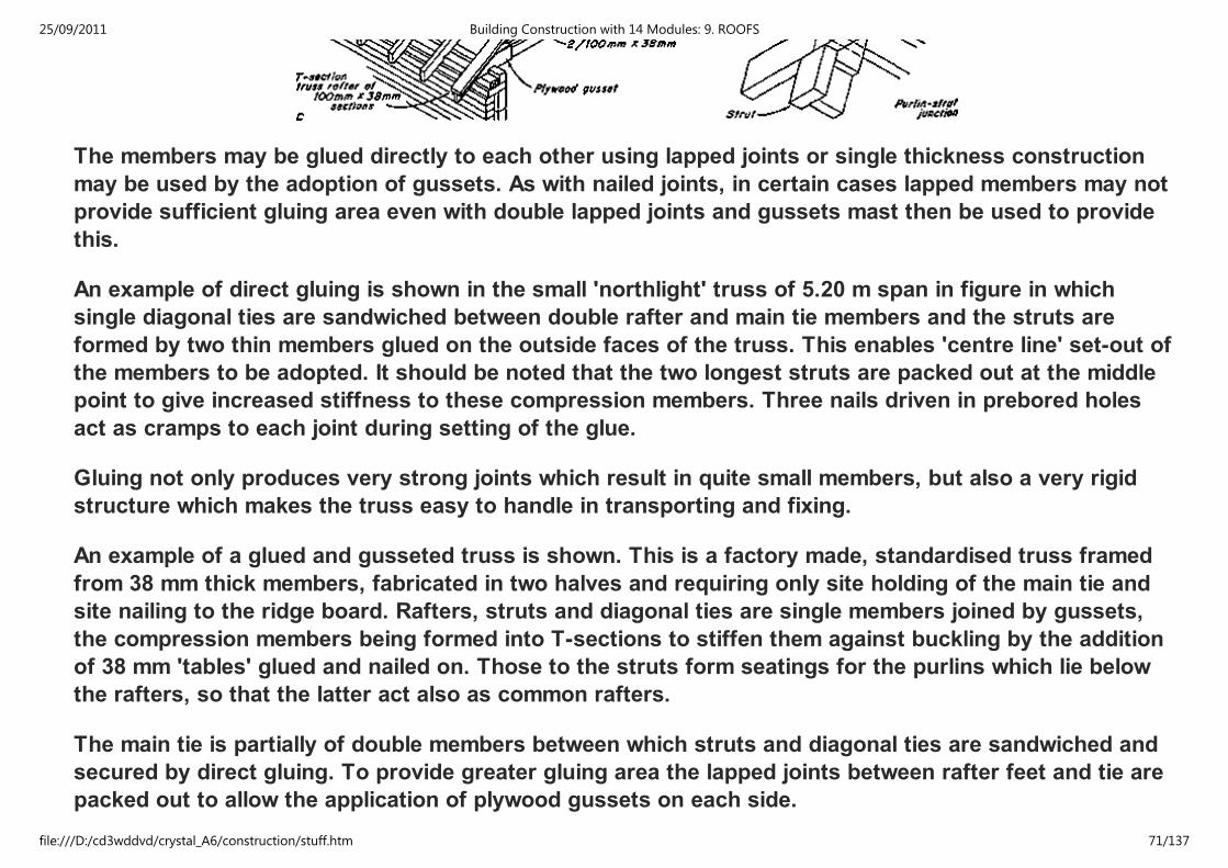
The members may be glued directly to each other using lapped joints or single thickness construction
may be used by the adoption of gussets. As with nailed joints, in certain cases lapped members may not
provide sufficient gluing area even with double lapped joints and gussets mast then be used to provide
this.
An example of direct gluing is shown in the small 'northlight' truss of 5.20 m span in figure in which
single diagonal ties are sandwiched between double rafter and main tie members and the struts are
formed by two thin members glued on the outside faces of the truss. This enables 'centre line' set-out of
the members to be adopted. It should be noted that the two longest struts are packed out at the middle
point to give increased stiffness to these compression members. Three nails driven in prebored holes
act as cramps to each joint during setting of the glue.
Gluing not only produces very strong joints which result in quite small members, but also a very rigid
structure which makes the truss easy to handle in transporting and fixing.
An example of a glued and gusseted truss is shown. This is a factory made, standardised truss framed
from 38 mm thick members, fabricated in two halves and requiring only site holding of the main tie and
site nailing to the ridge board. Rafters, struts and diagonal ties are single members joined by gussets,
the compression members being formed into T-sections to stiffen them against buckling by the addition
of 38 mm 'tables' glued and nailed on. Those to the struts form seatings for the purlins which lie below
the rafters, so that the latter act also as common rafters.
The main tie is partially of double members between which struts and diagonal ties are sandwiched and
secured by direct gluing. To provide greater gluing area the lapped joints between rafter feet and tie are
packed out to allow the application of plywood gussets on each side.
25/09/2011 Building Construction with 14 Modules: 9. ROOFS
file:///D:/cd3wddvd/crystal_A6/construction/stuff.htm 71/137

These trusses bear on the normal wall plate and are designed to be spaced up to 3.90 m apart for spans
from 4.5 m to 9.0 m
9.4.3.8 Trussed Rafters
25/09/2011 Building Construction with 14 Modules: 9. ROOFS
file:///D:/cd3wddvd/crystal_A6/construction/stuff.htm 72/137
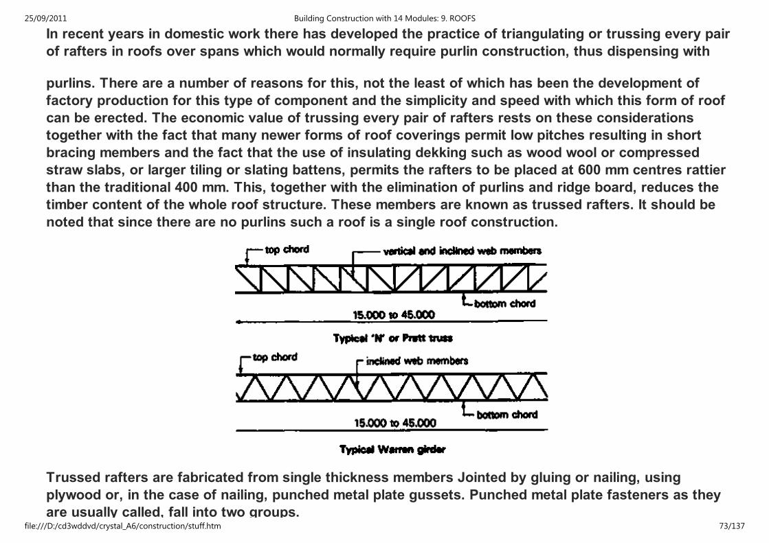
In recent years in domestic work there has developed the practice of triangulating or trussing every pair
of rafters in roofs over spans which would normally require purlin construction, thus dispensing with
purlins. There are a number of reasons for this, not the least of which has been the development of
factory production for this type of component and the simplicity and speed with which this form of roof
can be erected. The economic value of trussing every pair of rafters rests on these considerations
together with the fact that many newer forms of roof coverings permit low pitches resulting in short
bracing members and the fact that the use of insulating dekking such as wood wool or compressed
straw slabs, or larger tiling or slating battens, permits the rafters to be placed at 600 mm centres rattier
than the traditional 400 mm. This, together with the elimination of purlins and ridge board, reduces the
timber content of the whole roof structure. These members are known as trussed rafters. It should be
noted that since there are no purlins such a roof is a single roof construction.
Trussed rafters are fabricated from single thickness members Jointed by gluing or nailing, using
plywood or, in the case of nailing, punched metal plate gussets. Punched metal plate fasteners as they
are usually called, fall into two groups.
25/09/2011 Building Construction with 14 Modules: 9. ROOFS
file:///D:/cd3wddvd/crystal_A6/construction/stuff.htm 73/137
are usually called, fall into two groups.
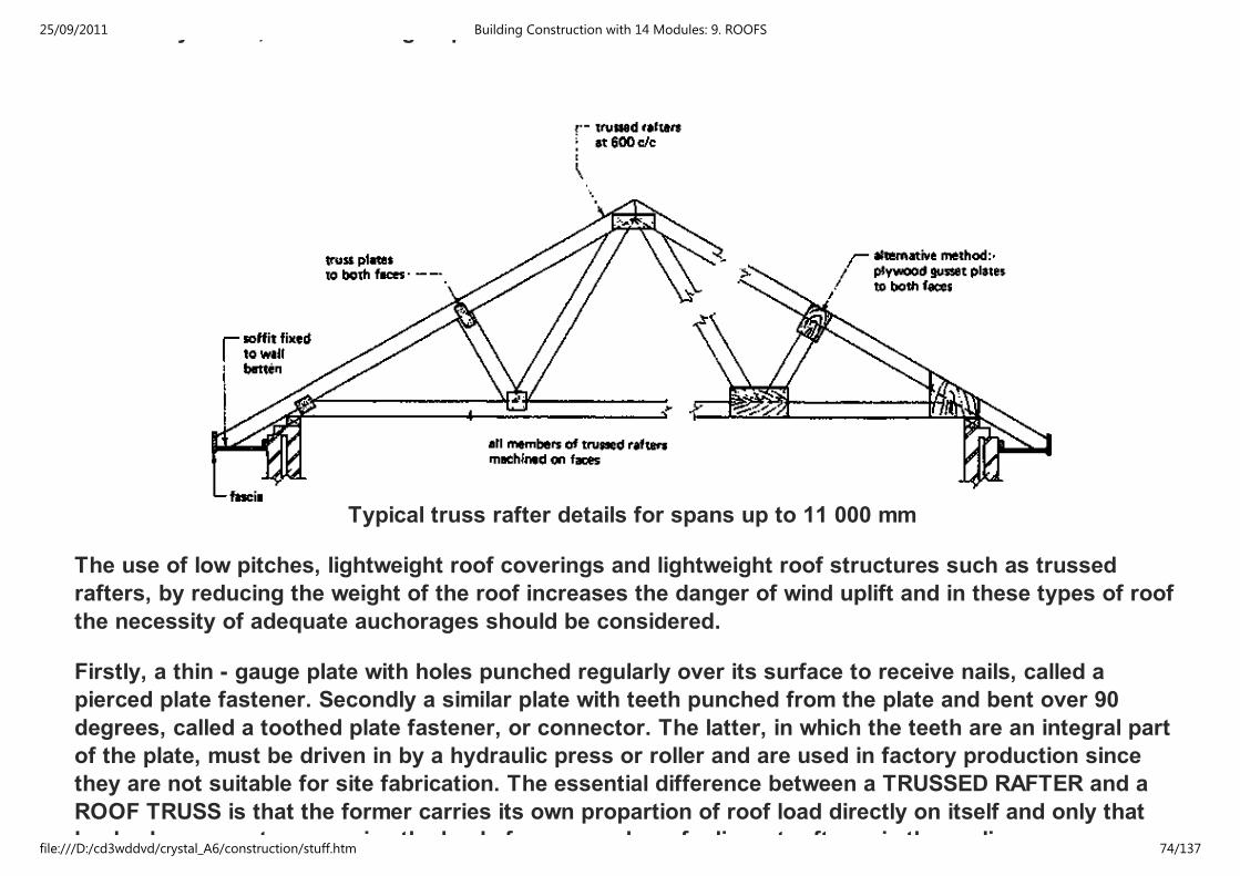
Typical truss rafter details for spans up to 11 000 mm
The use of low pitches, lightweight roof coverings and lightweight roof structures such as trussed
rafters, by reducing the weight of the roof increases the danger of wind uplift and in these types of roof
the necessity of adequate auchorages should be considered.
Firstly, a thin - gauge plate with holes punched regularly over its surface to receive nails, called a
pierced plate fastener. Secondly a similar plate with teeth punched from the plate and bent over 90
degrees, called a toothed plate fastener, or connector. The latter, in which the teeth are an integral part
of the plate, must be driven in by a hydraulic press or roller and are used in factory production since
they are not suitable for site fabrication. The essential difference between a TRUSSED RAFTER and a
ROOF TRUSS is that the former carries its own propartion of roof load directly on itself and only that
load, wherease a truss carries the loads from a number of adjacent rafters via the purlins.
25/09/2011 Building Construction with 14 Modules: 9. ROOFS
file:///D:/cd3wddvd/crystal_A6/construction/stuff.htm 74/137
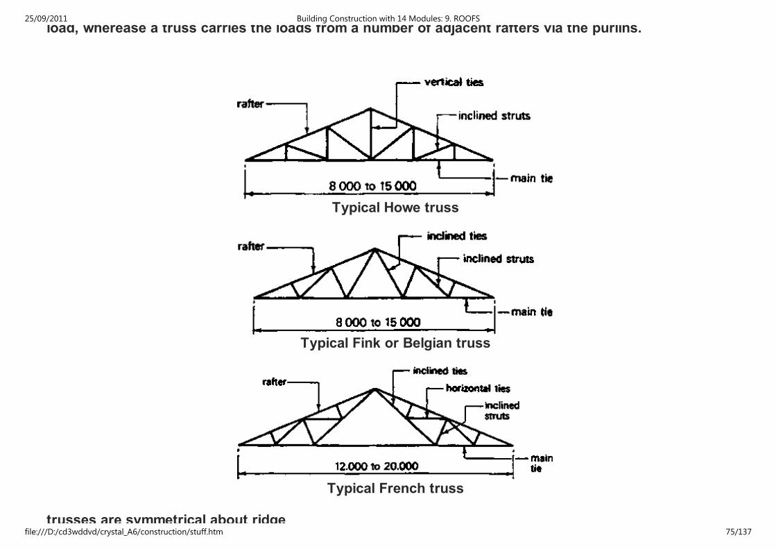
load, wherease a truss carries the loads from a number of adjacent rafters via the purlins.
Typical Howe truss
Typical Fink or Belgian truss
Typical French truss
trusses are symmetrical about ridge
25/09/2011 Building Construction with 14 Modules: 9. ROOFS
file:///D:/cd3wddvd/crystal_A6/construction/stuff.htm 75/137
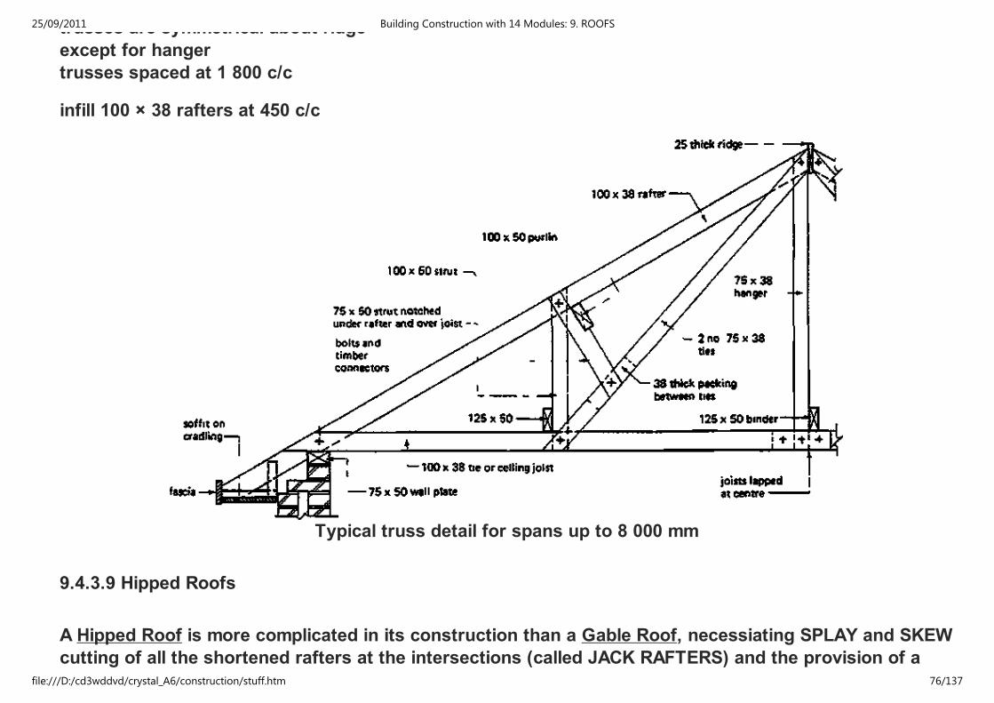
trusses are symmetrical about ridge
except for hanger
trusses spaced at 1 800 c/c
infill 100 × 38 rafters at 450 c/c
Typical truss detail for spans up to 8 000 mm
9.4.3.9 Hipped Roofs
A Hipped Roof is more complicated in its construction than a Gable Roof, necessiating SPLAY and SKEW
cutting of all the shortened rafters at the intersections (called JACK RAFTERS) and the provision of a
deep HIP RAFTER running from ridge to wall plate to carry their top ends (see fig.). The hip rafter
25/09/2011 Building Construction with 14 Modules: 9. ROOFS
file:///D:/cd3wddvd/crystal_A6/construction/stuff.htm 76/137

deep HIP RAFTER running from ridge to wall plate to carry their top ends (see fig.). The hip rafter
transfers their loads to the wall plate and will, therefore, be 225 mm to 280 mm deep, depending upon its
span and the depth of the rafters, and 38 mm to 50 mm thick. If the roof has purlins their ends will also
be carried by the hip rafters which may then need to be 75 mm thick. The tendency of the inclined thrust
of the hip rafter to push out the walls at the quoin is overcome by tying together the two wall plates on
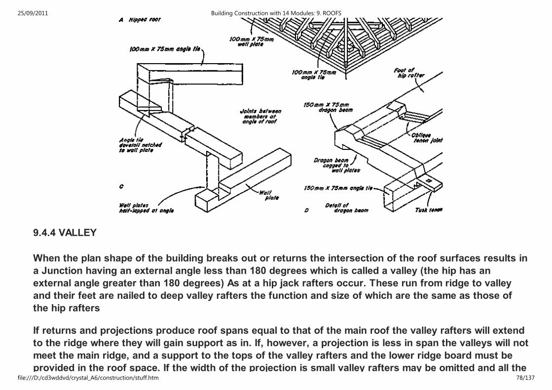
which it bears by an angle tie dovetail notched or bolted to the plates (fig.). The foot of the hip rafter ist
notched over the wall plates which are half-lapped to each other. If the rafter carries purlins causing a
greater thrust more resistance to this is provided by the introduction of a dragon-bean as shown in the
fig. linking the ends of the wall plates to the angle tie, which would be larger in size. The dragon-beam is
cogged over the plates and tusk-tenoned to the tie. A dragon-beam will in any case be necessary to
provide a bearing for the hip rafter when the eaves are sprocketed and the feet of the rafters terminate
on the wall plate.
25/09/2011 Building Construction with 14 Modules: 9. ROOFS
file:///D:/cd3wddvd/crystal_A6/construction/stuff.htm 77/137
9.4.4 VALLEY
When the plan shape of the building breaks out or returns the intersection of the roof surfaces results in
a Junction having an external angle less than 180 degrees which is called a valley (the hip has an
external angle greater than 180 degrees) As at a hip jack rafters occur. These run from ridge to valley
and their feet are nailed to deep valley rafters the function and size of which are the same as those of
the hip rafters
If returns and projections produce roof spans equal to that of the main roof the valley rafters will extend
to the ridge where they will gain support as in. If, however, a projection is less in span the valleys will not
meet the main ridge, and a support to the tops of the valley rafters and the lower ridge board must be
provided in the roof space. If the width of the projection is small valley rafters may be omitted and all the
25/09/2011 Building Construction with 14 Modules: 9. ROOFS
file:///D:/cd3wddvd/crystal_A6/construction/stuff.htm 78/137

provided in the roof space. If the width of the projection is small valley rafters may be omitted and all the
rafters of the main roof be carried down full length on to a suitable bearing with boards laid on them to
take the end of the ridge board and the feet of the jack rafters to the projection.
A valley is finished with a triangular timber fillet or a valley board, as shown in the fig. depending on the
width required by the nature of the junction between the roof covering on the two slopes.
It will be seen that the plan shape greatly affects the roof construction and when designing a building
which, is to be covered with a pitched roof the implications of the plan in this respect must be borne in
mind. The simple rectangular plan results in simple and relatively cheap roof construction; one in which
breaks and returns accur, especially if they are numerous, may result in most expensive construction.
This applies not only to the structure itself but also to the roof covereing
9.4.5 EAVES TREATMENT
As with a monopitch roof, unless the roof is set behind a parapet, the eaves of a ridge roof may finish
flush with or may project beyond the wall face, the former producing some economy in roof covering and
timber, the latter providing some protection to the walls. Detailing of construction varies widely
25/09/2011 Building Construction with 14 Modules: 9. ROOFS
file:///D:/cd3wddvd/crystal_A6/construction/stuff.htm 79/137
timber, the latter providing some protection to the walls. Detailing of construction varies widely
according to the pitch of the roof, the effect desired by the architect and whether an external or a hidden
gutter is used. It is, therefore, possible to illustrate only some typical examples.
Examples of open projecting caves are shown in the figeres. With tile or slate coverings of any type the
fascia projects as shown 19 mm oder so above the roofing battens in order to tilt the caves courses.
Where no fascia is used as at a batten of greater depth than the boarding or battens, called a tilting -
fillet, is used at this point. Also closed projecting eaves are shown in the figure. The variation in detailing
necessiated by increased projection can be seen. The ends of the rafters are cut horizontally to provide
some fixing for the soffit boards (C), but as a considerable portion of the boarding is not supported by
the rafter, soffit bearers are fixed to the rafter ends as shown. The back of the fascia should be grooved
to take the edge of the soffit. Greater projections necessitat longer soffit bearers and brackets are then
required to support their inner ends as shown in (D). When plywood or asbestos cement sheet is used
for the soffit, as is quite common, the fascia must be grooved to take the front edge and the back edge
should be given continuous support by a fillet secured to the wall (E). In this case the soffit bearers can
be fixed to this rather than to brackets from the rafters. If the roof pitch is not too great the soffit can be
fixed direct to the rafters and, with a gable roof and projecting barge board, can continue up as the
verge soffit. In this particular case the barge-board will be slightly less in depth than the fascia, but with
a horizontal eaves soffit it must be deeper in order to cover the end of the eaves, in which case the outer
and cantilever rafters which support it must be deeper than the common rafters or a thicker barge-board
must be used.
If a clear fascia, unobstructed by an external gutter, is desired an internal gutter may be formed. It is
essential that the front edge of this type of gutter be at such a level that in the event of blockage of the
outlet water will drain over the front rather than seep back into the roof structure and possibly into the
building.
25/09/2011 Building Construction with 14 Modules: 9. ROOFS
file:///D:/cd3wddvd/crystal_A6/construction/stuff.htm 80/137
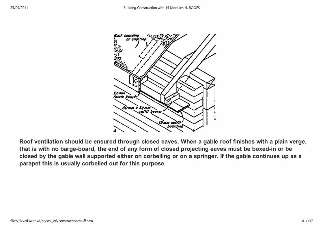
Roof ventilation should be ensured through closed eaves. When a gable roof finishes with a plain verge,
that is with no barge-board, the end of any form of closed projecting eaves must be boxed-in or be
closed by the gable wall supported either on corbelling or on a springer. If the gable continues up as a
parapet this is usually corbelled out for this purpose.
25/09/2011 Building Construction with 14 Modules: 9. ROOFS
file:///D:/cd3wddvd/crystal_A6/construction/stuff.htm 81/137
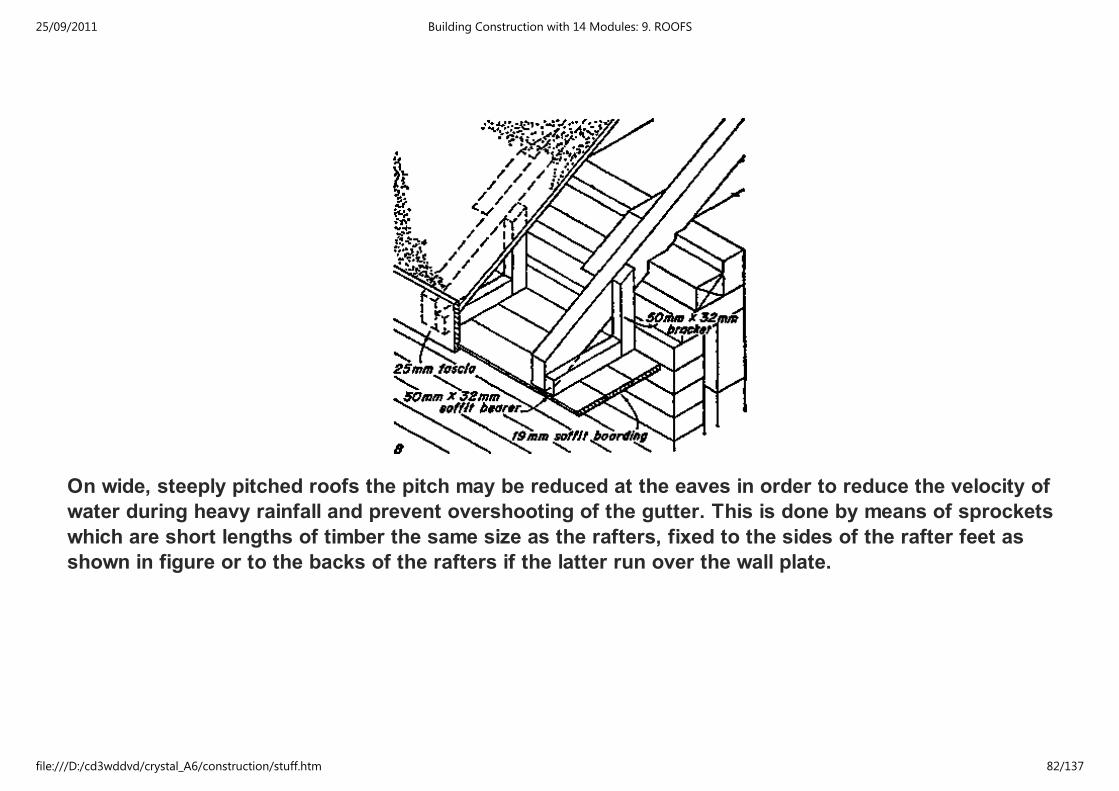
On wide, steeply pitched roofs the pitch may be reduced at the eaves in order to reduce the velocity of
water during heavy rainfall and prevent overshooting of the gutter. This is done by means of sprockets
which are short lengths of timber the same size as the rafters, fixed to the sides of the rafter feet as
shown in figure or to the backs of the rafters if the latter run over the wall plate.
25/09/2011 Building Construction with 14 Modules: 9. ROOFS
file:///D:/cd3wddvd/crystal_A6/construction/stuff.htm 82/137
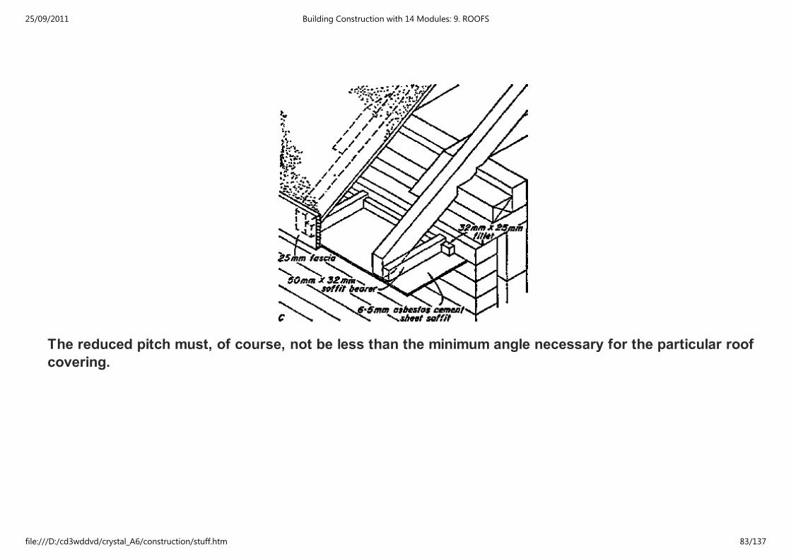
The reduced pitch must, of course, not be less than the minimum angle necessary for the particular roof
covering.
25/09/2011 Building Construction with 14 Modules: 9. ROOFS
file:///D:/cd3wddvd/crystal_A6/construction/stuff.htm 83/137
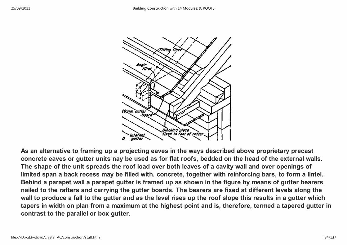
As an alternative to framing up a projecting eaves in the ways described above proprietary precast
concrete eaves or gutter units nay be used as for flat roofs, bedded on the head of the external walls.
The shape of the unit spreads the roof load over both leaves of a cavity wall and over openings of
limited span a back recess may be filled with. concrete, together with reinforcing bars, to form a lintel.
Behind a parapet wall a parapet gutter is framed up as shown in the figure by means of gutter bearers
nailed to the rafters and carrying the gutter boards. The bearers are fixed at different levels along the
wall to produce a fall to the gutter and as the level rises up the roof slope this results in a gutter which
tapers in width on plan from a maximum at the highest point and is, therefore, termed a tapered gutter in
contrast to the parallel or box gutter.
25/09/2011 Building Construction with 14 Modules: 9. ROOFS
file:///D:/cd3wddvd/crystal_A6/construction/stuff.htm 84/137

25/09/2011 Building Construction with 14 Modules: 9. ROOFS
file:///D:/cd3wddvd/crystal_A6/construction/stuff.htm 85/137
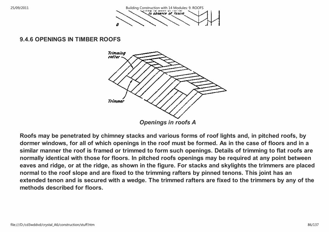
9.4.6 OPENINGS IN TIMBER ROOFS
Openings in roofs A
Roofs may be penetrated by chimney stacks and various forms of roof lights and, in pitched roofs, by
dormer windows, for all of which openings in the roof must be formed. As in the case of floors and in a
similar manner the roof is framed or trimmed to form such openings. Details of trimming to flat roofs are
normally identical with those for floors. In pitched roofs openings may be required at any point between
eaves and ridge, or at the ridge, as shown in the figure. For stacks and skylights the trimmers are placed
normal to the roof slope and are fixed to the trimming rafters by pinned tenons. This joint has an
extended tenon and is secured with a wedge. The trimmed rafters are fixed to the trimmers by any of the
methods described for floors.
25/09/2011 Building Construction with 14 Modules: 9. ROOFS
file:///D:/cd3wddvd/crystal_A6/construction/stuff.htm 86/137

B Trimming to roof lights and stacks
Openings for roof lights are finished with a timber upstand or CURB as indicated in the figure which in a
pitched roof, raises the light above the level of the roof covering and permits a watertight junction to be
formed all round, and in a flat roof provides for a 150 mm upturn of the roof finish.
C
25/09/2011 Building Construction with 14 Modules: 9. ROOFS
file:///D:/cd3wddvd/crystal_A6/construction/stuff.htm 87/137
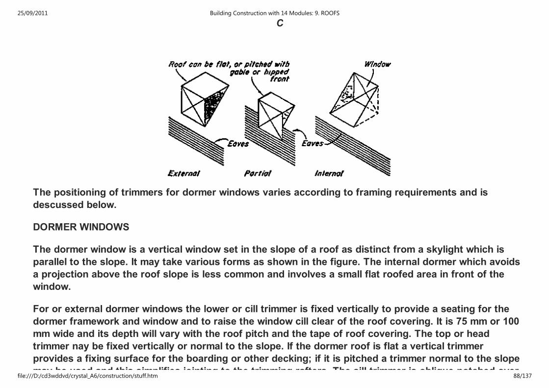
C
The positioning of trimmers for dormer windows varies according to framing requirements and is
descussed below.
DORMER WINDOWS
The dormer window is a vertical window set in the slope of a roof as distinct from a skylight which is
parallel to the slope. It may take various forms as shown in the figure. The internal dormer which avoids
a projection above the roof slope is less common and involves a small flat roofed area in front of the
window.
For or external dormer windows the lower or cill trimmer is fixed vertically to provide a seating for the
dormer framework and window and to raise the window cill clear of the roof covering. It is 75 mm or 100
mm wide and its depth will vary with the roof pitch and the tape of roof covering. The top or head
trimmer nay be fixed vertically or normal to the slope. If the dormer roof is flat a vertical trimmer
provides a fixing surface for the boarding or other decking; if it is pitched a trimmer normal to the slope
may be used and this simplifies jointing to the trimming rafters. The sill trimmer is oblique notched over
25/09/2011 Building Construction with 14 Modules: 9. ROOFS
file:///D:/cd3wddvd/crystal_A6/construction/stuff.htm 88/137
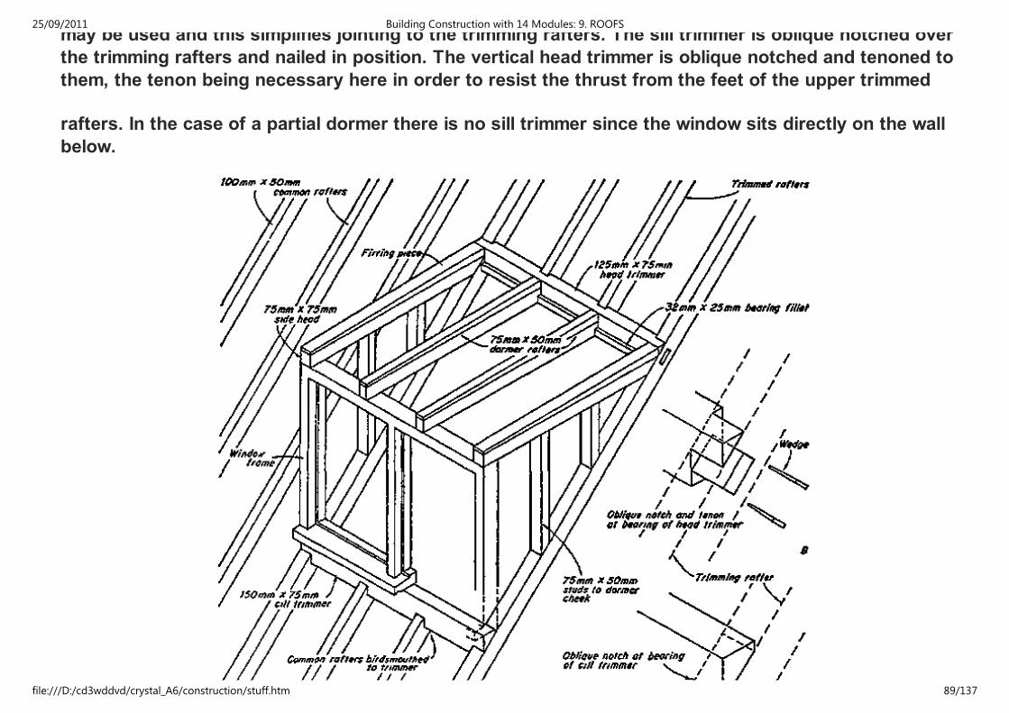
may be used and this simplifies jointing to the trimming rafters. The sill trimmer is oblique notched over
the trimming rafters and nailed in position. The vertical head trimmer is oblique notched and tenoned to
them, the tenon being necessary here in order to resist the thrust from the feet of the upper trimmed
rafters. In the case of a partial dormer there is no sill trimmer since the window sits directly on the wall
below.
25/09/2011 Building Construction with 14 Modules: 9. ROOFS
file:///D:/cd3wddvd/crystal_A6/construction/stuff.htm 89/137
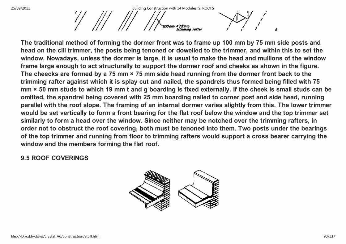
The traditional method of forming the dormer front was to frame up 100 mm by 75 mm side posts and
head on the cill trimmer, the posts being tenoned or dowelled to the trimmer, and within this to set the
window. Nowadays, unless the dormer is large, it is usual to make the head and mullions of the window
frame large enough to act structurally to support the dormer roof and cheeks as shown in the figure.
The cheecks are formed by a 75 mm × 75 mm side head running from the dormer front back to the
trimming rafter against which it is splay cut and nailed, the spandrels thus formed being filled with 75
mm × 50 mm studs to which 19 mm t and g boarding is fixed externally. If the cheek is small studs can be
omitted, the spandrel being covered with 25 mm boarding nailed to corner post and side head, running
parallel with the roof slope. The framing of an internal dormer varies slightly from this. The lower trimmer
would be set vertically to form a front bearing for the flat roof below the window and the top trimmer set
similarly to form a head over the window. Since neither may be notched over the trimming rafters, in
order not to obstruct the roof covering, both must be tenoned into them. Two posts under the bearings
of the top trimmer and running from floor to trimming rafters would support a cross bearer carrying the
window and the members forming the flat roof.
9.5 ROOF COVERINGS
25/09/2011 Building Construction with 14 Modules: 9. ROOFS
file:///D:/cd3wddvd/crystal_A6/construction/stuff.htm 90/137
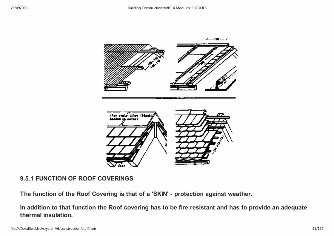
9.5.1 FUNCTION OF ROOF COVERINGS
The function of the Roof Covering is that of a 'SKIN' - protection against weather.
In addition to that function the Roof covering has to be fire resistant and has to provide an adequate
thermal insulation.
25/09/2011 Building Construction with 14 Modules: 9. ROOFS
file:///D:/cd3wddvd/crystal_A6/construction/stuff.htm 91/137
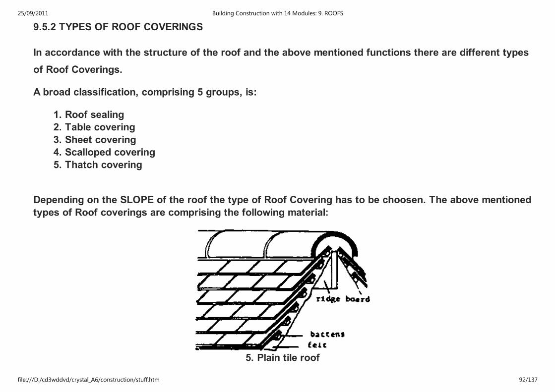
9.5.2 TYPES OF ROOF COVERINGS
In accordance with the structure of the roof and the above mentioned functions there are different types
of Roof Coverings.
A broad classification, comprising 5 groups, is:
1. Roof sealing
2. Table covering
3. Sheet covering
4. Scalloped covering
5. Thatch covering
Depending on the SLOPE of the roof the type of Roof Covering has to be choosen. The above mentioned
types of Roof coverings are comprising the following material:
5. Plain tile roof
25/09/2011 Building Construction with 14 Modules: 9. ROOFS
file:///D:/cd3wddvd/crystal_A6/construction/stuff.htm 92/137
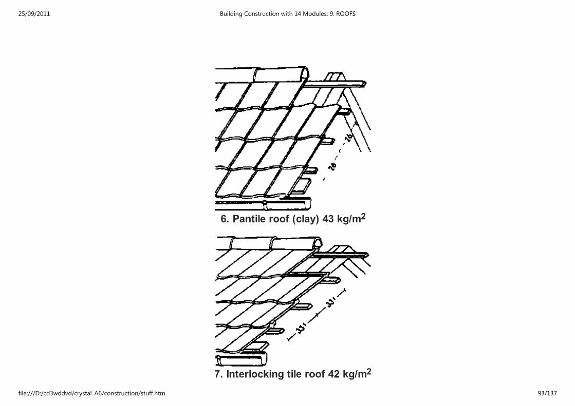
6. Pantile roof (clay) 43 kg/m2
7. Interlocking tile roof 42 kg/m2
25/09/2011 Building Construction with 14 Modules: 9. ROOFS
file:///D:/cd3wddvd/crystal_A6/construction/stuff.htm 93/137

8. Thatch roof 10 kg/m2
9. Corrugated Eternit roof 17 kg/m2
25/09/2011 Building Construction with 14 Modules: 9. ROOFS
file:///D:/cd3wddvd/crystal_A6/construction/stuff.htm 94/137
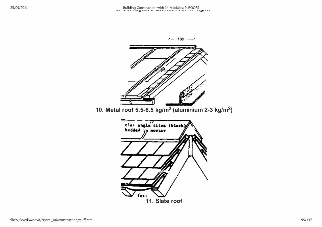
9. Corrugated Eternit roof 17 kg/m
10. Metal roof 5.5-6.5 kg/m2 (aluminium 2-3 kg/m2)
11. Slate roof
25/09/2011 Building Construction with 14 Modules: 9. ROOFS
file:///D:/cd3wddvd/crystal_A6/construction/stuff.htm 95/137

12. Double roof ('Doppeldach') 63 kg/m2
1 Roof sealing:
- heat sealed plastic foils;
- roofing felts, glued in different layers, sealed with bitumious paints.
- reinforced with metal fails, etc.
2 Table covering:
- asphaltic or bitumious felts, glued or nailed in 1, 2, or 3 layers.
They are colled according to the weight of the raw-materials (333 g/m2 or 500 g/m2).
25/09/2011 Building Construction with 14 Modules: 9. ROOFS
file:///D:/cd3wddvd/crystal_A6/construction/stuff.htm 96/137
They are colled according to the weight of the raw-materials (333 g/m or 500 g/m ).
The raw-felt is soaked with tar or bitumen and coated. Sand or chippings may be pressed on the
surface of the felt as protection against mechanical loads and weather.
3 Sheet covering:
- 3heet metal (coated or galvanized)
- galvanized corrugated iron sheets
- corrugated aluminium sheets
- corrugated asbestos sheets.
4 Scalloped coverings:
- Roofing (clay) tiles
- Concrete tiles
- Slates
- Asbestos plain tiles (in different forms and shapes)
- shingles.
5 Thatch coverings:
- straw
- dry grass, or hey
- reed
9.5.3 SUBSTRUCTURES
25/09/2011 Building Construction with 14 Modules: 9. ROOFS
file:///D:/cd3wddvd/crystal_A6/construction/stuff.htm 97/137
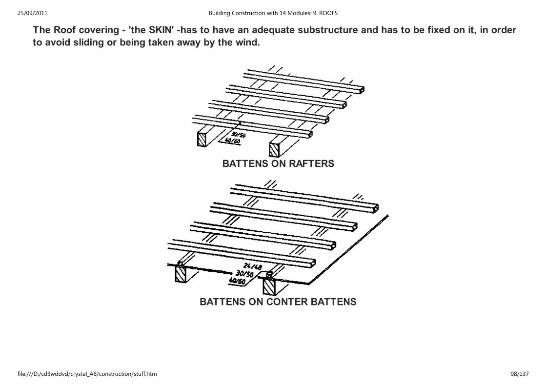
The Roof covering - 'the SKIN' -has to have an adequate substructure and has to be fixed on it, in order
to avoid sliding or being taken away by the wind.
BATTENS ON RAFTERS
BATTENS ON CONTER BATTENS
25/09/2011 Building Construction with 14 Modules: 9. ROOFS
file:///D:/cd3wddvd/crystal_A6/construction/stuff.htm 98/137
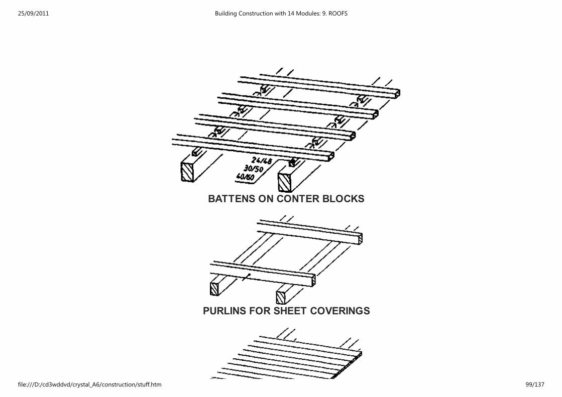
BATTENS ON CONTER BLOCKS
PURLINS FOR SHEET COVERINGS
25/09/2011 Building Construction with 14 Modules: 9. ROOFS
file:///D:/cd3wddvd/crystal_A6/construction/stuff.htm 99/137
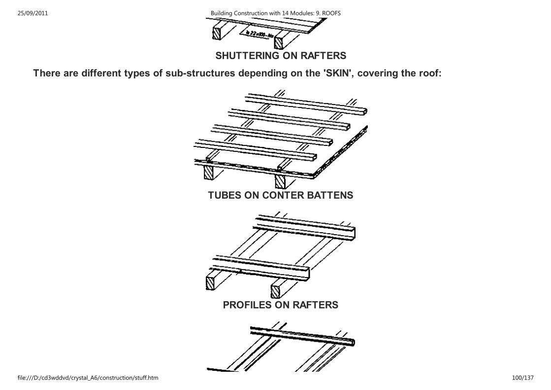
SHUTTERING ON RAFTERS
There are different types of sub-structures depending on the 'SKIN', covering the roof:
TUBES ON CONTER BATTENS
PROFILES ON RAFTERS
25/09/2011 Building Construction with 14 Modules: 9. ROOFS
file:///D:/cd3wddvd/crystal_A6/construction/stuff.htm 100/137
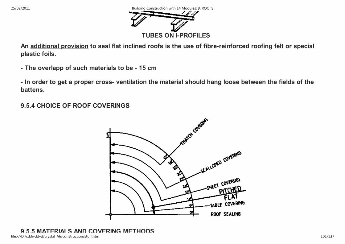
TUBES ON I-PROFILES
An additional provision to seal flat inclined roofs is the use of fibre-reinforced roofing felt or special
plastic foils.
- The overlapp of such materials to be - 15 cm
- In order to get a proper cross- ventilation the material should hang loose between the fields of the
battens.
9.5.4 CHOICE OF ROOF COVERINGS
9.5.5 MATERIALS AND COVERING METHODS
25/09/2011 Building Construction with 14 Modules: 9. ROOFS
file:///D:/cd3wddvd/crystal_A6/construction/stuff.htm 101/137
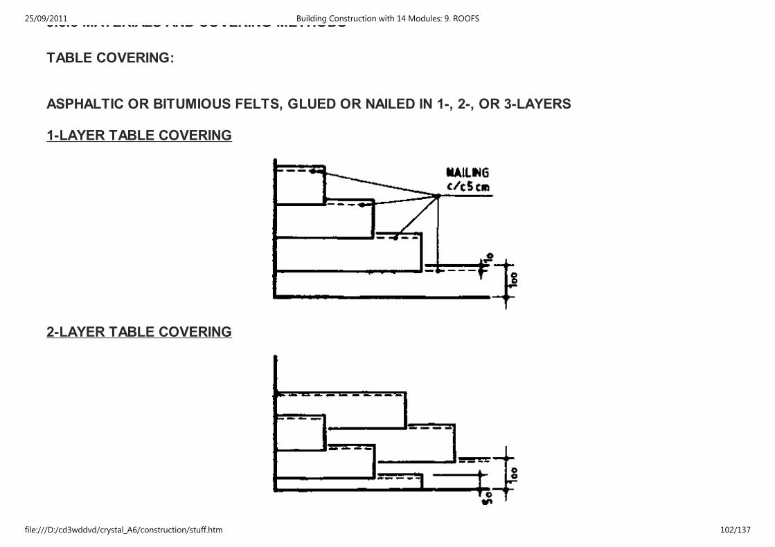
9.5.5 MATERIALS AND COVERING METHODS
TABLE COVERING:
ASPHALTIC OR BITUMIOUS FELTS, GLUED OR NAILED IN 1-, 2-, OR 3-LAYERS
1-LAYER TABLE COVERING
2-LAYER TABLE COVERING
25/09/2011 Building Construction with 14 Modules: 9. ROOFS
file:///D:/cd3wddvd/crystal_A6/construction/stuff.htm 102/137
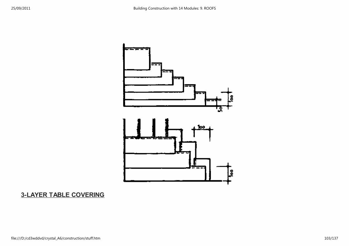
3-LAYER TABLE COVERING
25/09/2011 Building Construction with 14 Modules: 9. ROOFS
file:///D:/cd3wddvd/crystal_A6/construction/stuff.htm 103/137

SHEET COVERINGS:
SHEET METAL COVERINGS
- Sheet metal coverings provide an excellent protection against wind and rain, is durable and lighter in
weight than tiles, slates or asphalts.
Metal roofs are noisy.
Four types of metals are used for sheet coverings:
1. Lead
2. Copper
3. Zinc
4. Aluminium
25/09/2011 Building Construction with 14 Modules: 9. ROOFS
file:///D:/cd3wddvd/crystal_A6/construction/stuff.htm 104/137
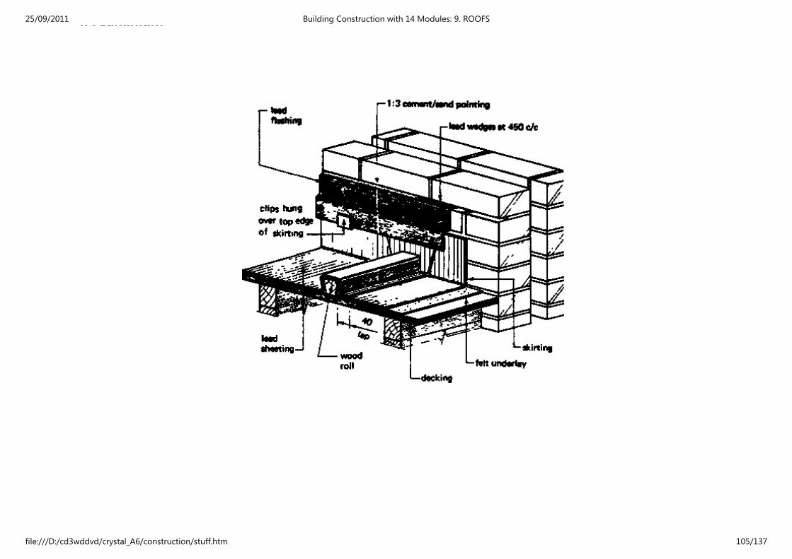
4. Aluminium25/09/2011 Building Construction with 14 Modules: 9. ROOFS
file:///D:/cd3wddvd/crystal_A6/construction/stuff.htm 105/137

25/09/2011 Building Construction with 14 Modules: 9. ROOFS
file:///D:/cd3wddvd/crystal_A6/construction/stuff.htm 106/137
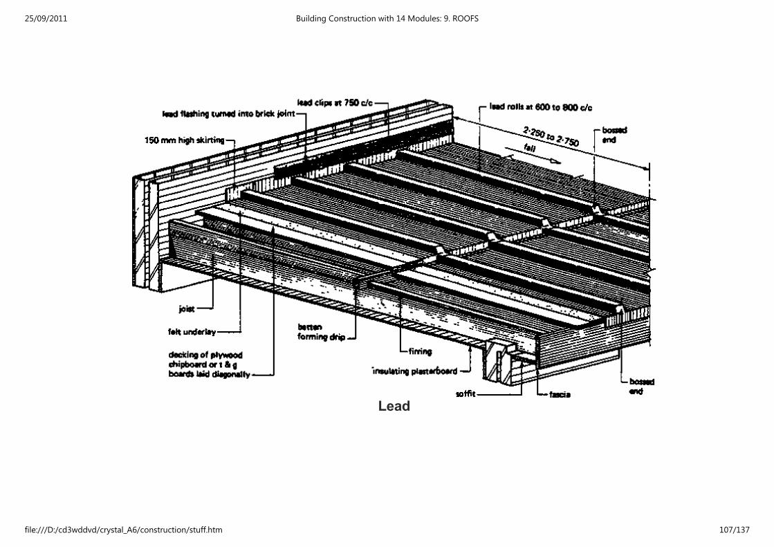
Lead
25/09/2011 Building Construction with 14 Modules: 9. ROOFS
file:///D:/cd3wddvd/crystal_A6/construction/stuff.htm 107/137
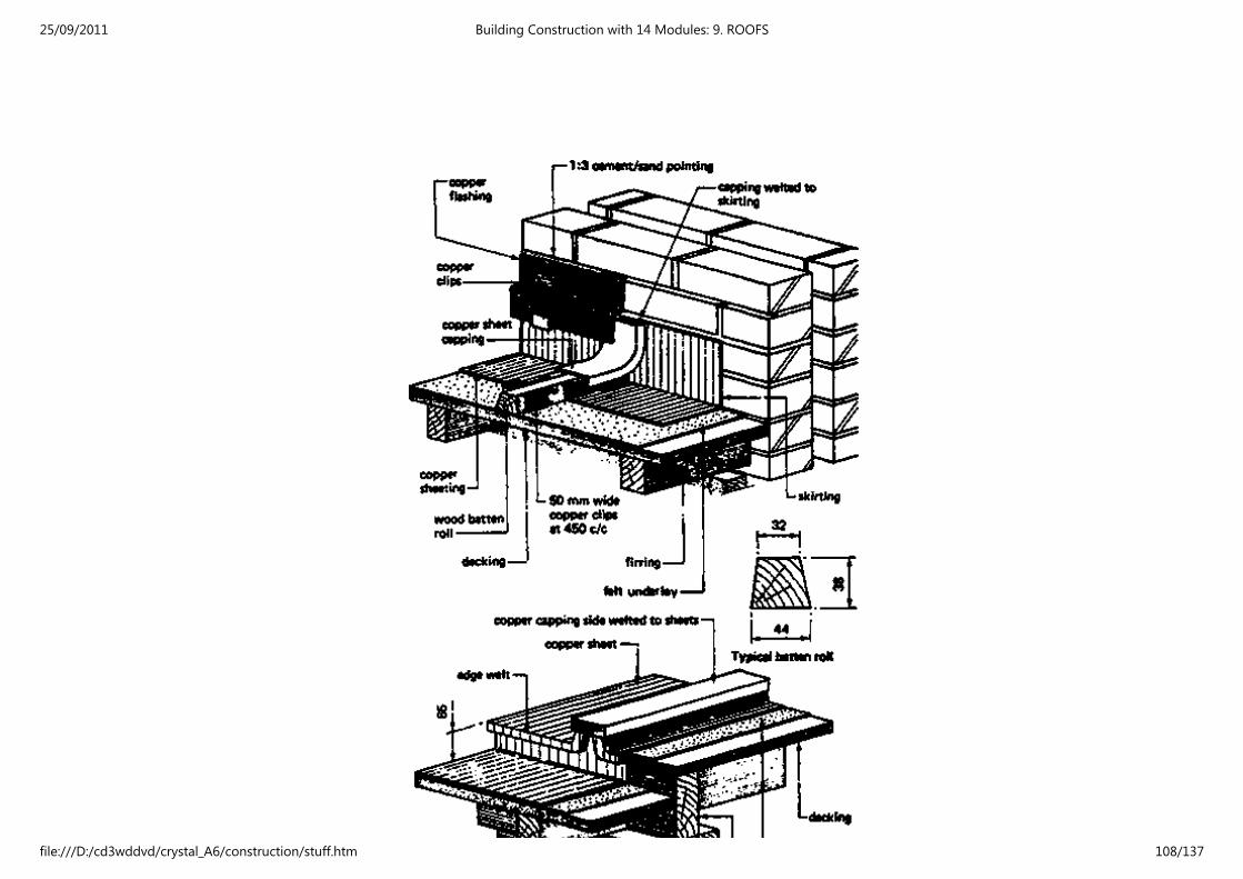
25/09/2011 Building Construction with 14 Modules: 9. ROOFS
file:///D:/cd3wddvd/crystal_A6/construction/stuff.htm 108/137

Copper
ASBESTOS SHEET COVERING:
LAYING OF THE 2. AND 3. SHEET WITH CORNERCUT
25/09/2011 Building Construction with 14 Modules: 9. ROOFS
file:///D:/cd3wddvd/crystal_A6/construction/stuff.htm 109/137

25/09/2011 Building Construction with 14 Modules: 9. ROOFS
file:///D:/cd3wddvd/crystal_A6/construction/stuff.htm 110/137
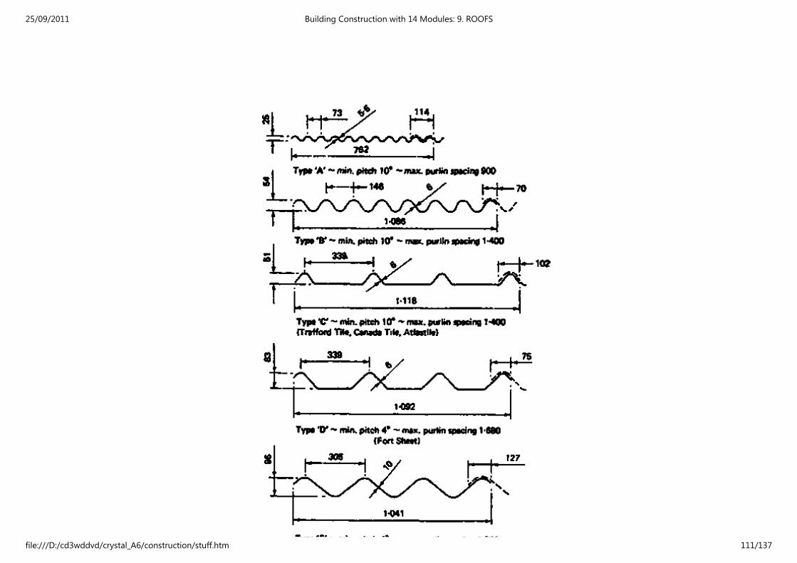
25/09/2011 Building Construction with 14 Modules: 9. ROOFS
file:///D:/cd3wddvd/crystal_A6/construction/stuff.htm 111/137

Typical asbestos cement sheet profiles
minimum end lap for all types = 150
All sheets are available in lengths from 900 to 3.000 in 150 mm increments For other profiles see BS 690
Typical fittings for type 'B' sheeting
25/09/2011 Building Construction with 14 Modules: 9. ROOFS
file:///D:/cd3wddvd/crystal_A6/construction/stuff.htm 112/137
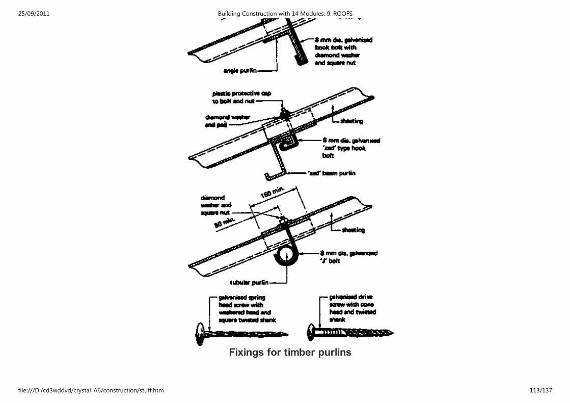
Fixings for timber purlins
25/09/2011 Building Construction with 14 Modules: 9. ROOFS
file:///D:/cd3wddvd/crystal_A6/construction/stuff.htm 113/137
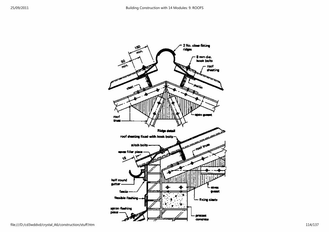
25/09/2011 Building Construction with 14 Modules: 9. ROOFS
file:///D:/cd3wddvd/crystal_A6/construction/stuff.htm 114/137
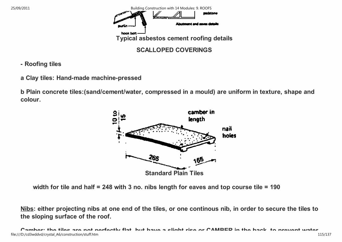
Typical asbestos cement roofing details
SCALLOPED COVERINGS
- Roofing tiles
a Clay tiles: Hand-made machine-pressed
b Plain concrete tiles:(sand/cement/water, compressed in a mould) are uniform in texture, shape and
colour.
Standard Plain Tiles
width for tile and half = 248 with 3 no. nibs length for eaves and top course tile = 190
Nibs: either projecting nibs at one end of the tiles, or one continous nib, in order to secure the tiles to
the sloping surface of the roof.
Camber: the tiles are not perfectly flat, but have a slight rise or CAMBER in the back, to prevent water
25/09/2011 Building Construction with 14 Modules: 9. ROOFS
file:///D:/cd3wddvd/crystal_A6/construction/stuff.htm 115/137
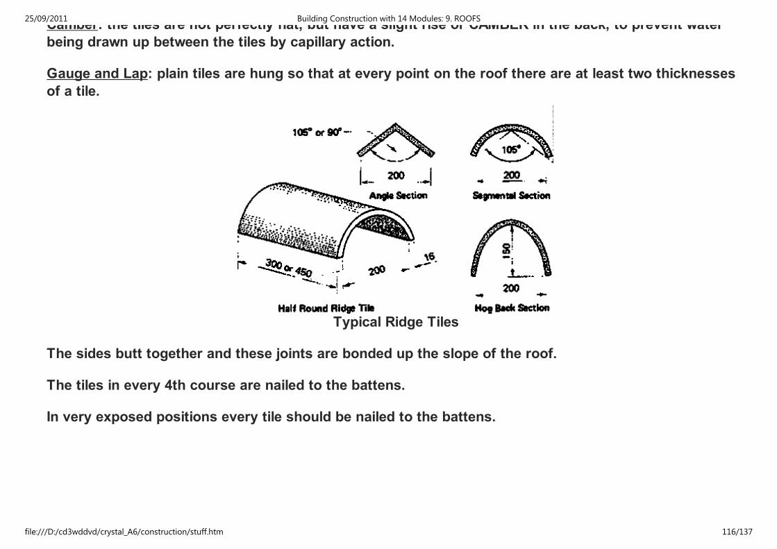
Camber: the tiles are not perfectly flat, but have a slight rise or CAMBER in the back, to prevent water
being drawn up between the tiles by capillary action.
Gauge and Lap: plain tiles are hung so that at every point on the roof there are at least two thicknesses
of a tile.
Typical Ridge Tiles
The sides butt together and these joints are bonded up the slope of the roof.
The tiles in every 4th course are nailed to the battens.
In very exposed positions every tile should be nailed to the battens.
25/09/2011 Building Construction with 14 Modules: 9. ROOFS
file:///D:/cd3wddvd/crystal_A6/construction/stuff.htm 116/137
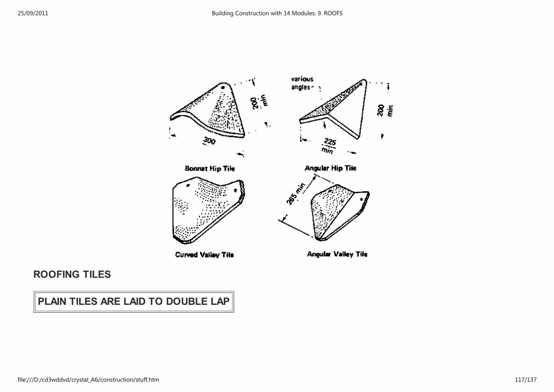
ROOFING TILES
PLAIN TILES ARE LAID TO DOUBLE LAP
25/09/2011 Building Construction with 14 Modules: 9. ROOFS
file:///D:/cd3wddvd/crystal_A6/construction/stuff.htm 117/137

Eaves:
A double coarse overhangs the fascia board some 40 mm.(in order to shed water into the eaves gutter)
25/09/2011 Building Construction with 14 Modules: 9. ROOFS
file:///D:/cd3wddvd/crystal_A6/construction/stuff.htm 118/137
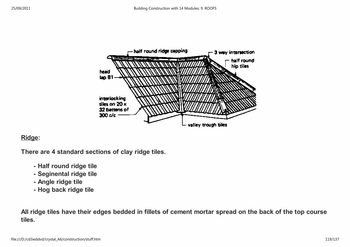
Ridge:
There are 4 standard sections of clay ridge tiles.
- Half round ridge tile
- Seginental ridge tile
- Angle ridge tile
- Hog back ridge tile
All ridge tiles have their edges bedded in fillets of cement mortar spread on the back of the top course
tiles.
25/09/2011 Building Construction with 14 Modules: 9. ROOFS
file:///D:/cd3wddvd/crystal_A6/construction/stuff.htm 119/137

Hips:
Kay be covered with ridge tiles bedded in exactly the same way as on ridges.
To prevent the tiles from slipping down, a galvanized iron or wrought-iron hip iron is fixed to the hip or
fascia.
The tiles next to the hip have to be cut to fit against the side of the hip rafter so that they lie under the
hip tiles.
25/09/2011 Building Construction with 14 Modules: 9. ROOFS
file:///D:/cd3wddvd/crystal_A6/construction/stuff.htm 120/137
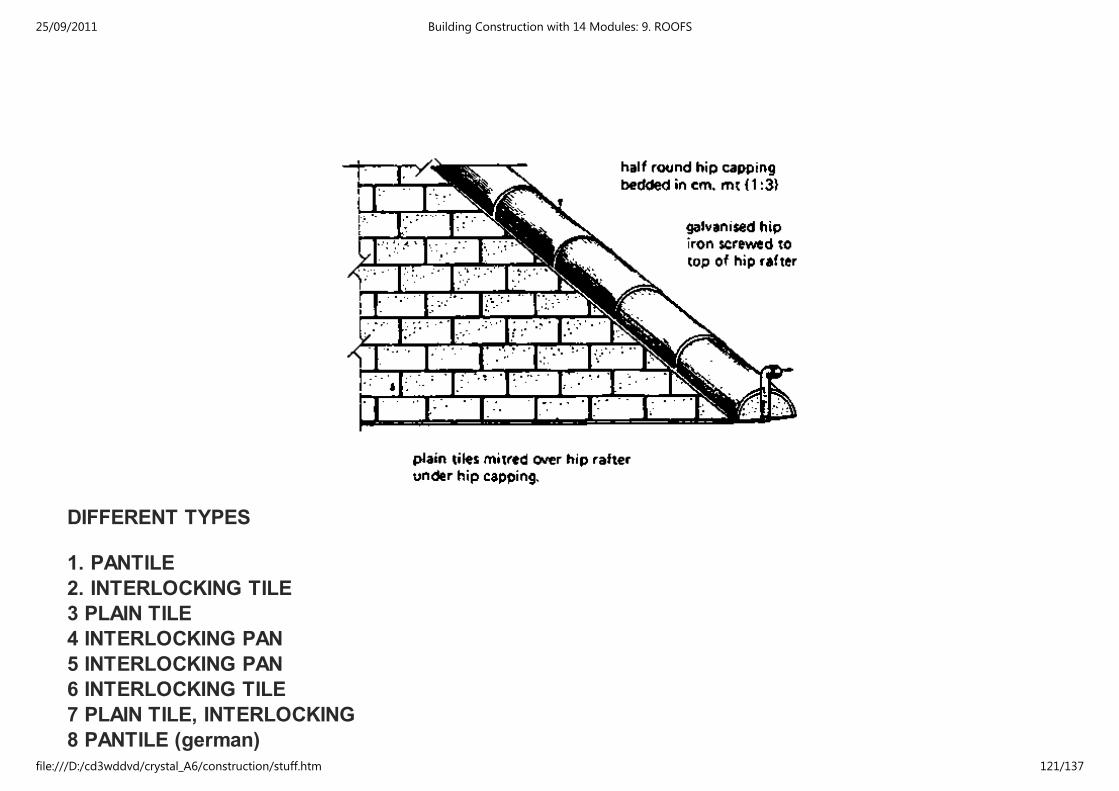
DIFFERENT TYPES
1. PANTILE
2. INTERLOCKING TILE
3 PLAIN TILE
4 INTERLOCKING PAN
5 INTERLOCKING PAN
6 INTERLOCKING TILE
7 PLAIN TILE, INTERLOCKING
8 PANTILE (german)
9 FLATROOF PAN
25/09/2011 Building Construction with 14 Modules: 9. ROOFS
file:///D:/cd3wddvd/crystal_A6/construction/stuff.htm 121/137
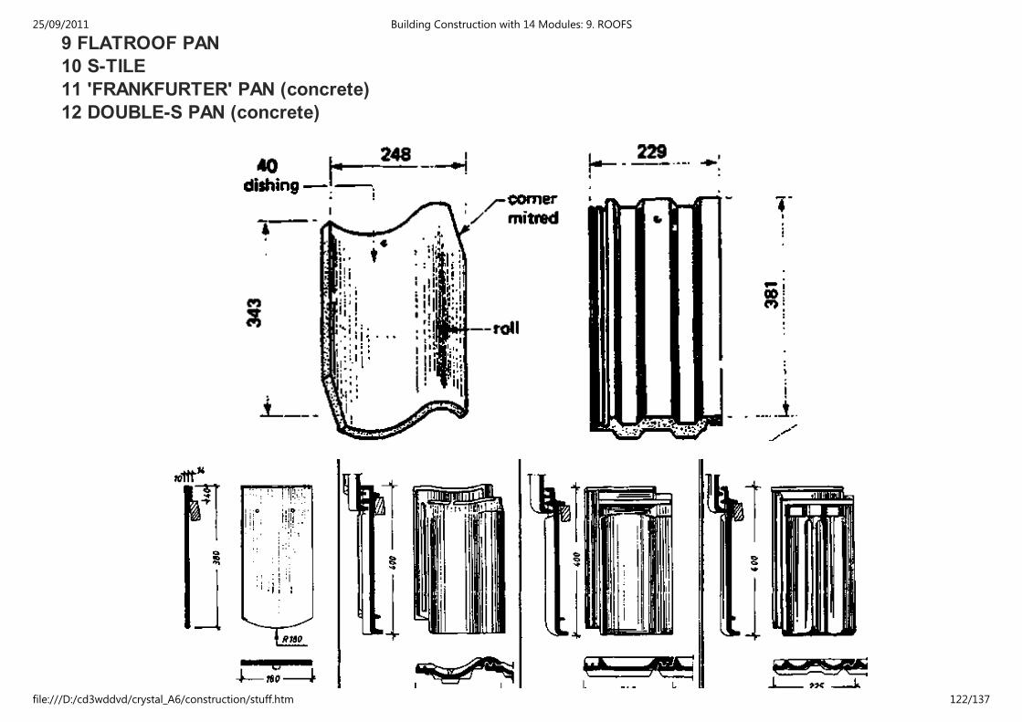
9 FLATROOF PAN
10 S-TILE
11 'FRANKFURTER' PAN (concrete)
12 DOUBLE-S PAN (concrete)
25/09/2011 Building Construction with 14 Modules: 9. ROOFS
file:///D:/cd3wddvd/crystal_A6/construction/stuff.htm 122/137
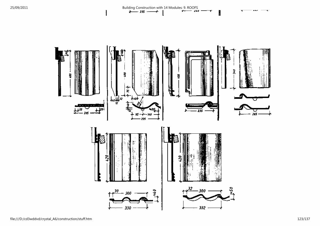
25/09/2011 Building Construction with 14 Modules: 9. ROOFS
file:///D:/cd3wddvd/crystal_A6/construction/stuff.htm 123/137
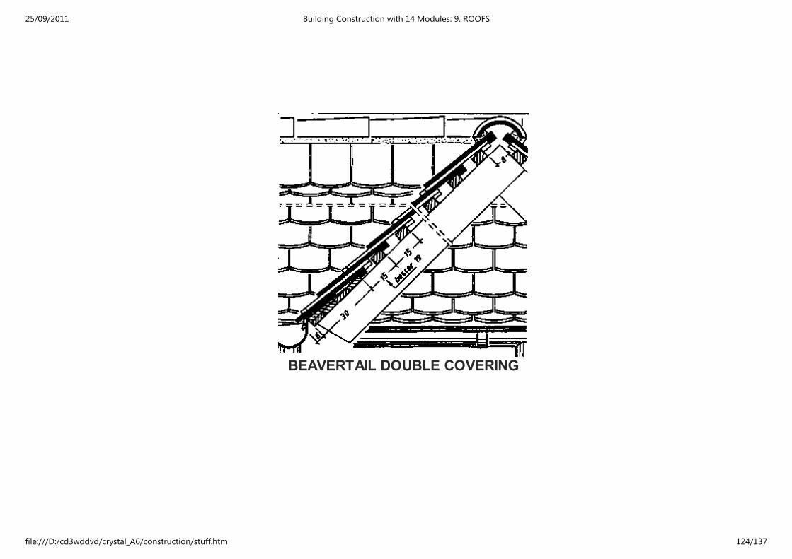
BEAVERTAIL DOUBLE COVERING
25/09/2011 Building Construction with 14 Modules: 9. ROOFS
file:///D:/cd3wddvd/crystal_A6/construction/stuff.htm 124/137
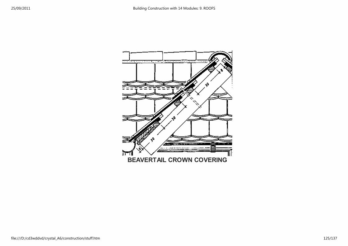
BEAVERTAIL CROWN COVERING
25/09/2011 Building Construction with 14 Modules: 9. ROOFS
file:///D:/cd3wddvd/crystal_A6/construction/stuff.htm 125/137

ROMAN TILE COVERING
25/09/2011 Building Construction with 14 Modules: 9. ROOFS
file:///D:/cd3wddvd/crystal_A6/construction/stuff.htm 126/137
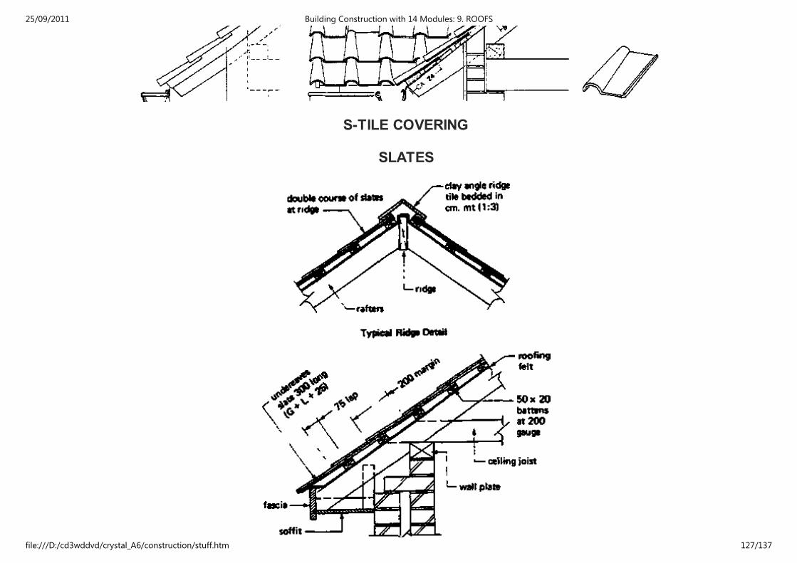
S-TILE COVERING
SLATES
25/09/2011 Building Construction with 14 Modules: 9. ROOFS
file:///D:/cd3wddvd/crystal_A6/construction/stuff.htm 127/137

Head Nailed Slating Using 500 × 250 slates
Centre Nailed Slating Using 600 × 300 slates
ASBESTOS SLATES
25/09/2011 Building Construction with 14 Modules: 9. ROOFS
file:///D:/cd3wddvd/crystal_A6/construction/stuff.htm 128/137

25/09/2011 Building Construction with 14 Modules: 9. ROOFS
file:///D:/cd3wddvd/crystal_A6/construction/stuff.htm 129/137
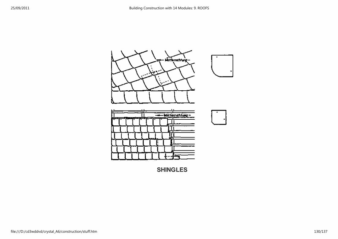
SHINGLES
25/09/2011 Building Construction with 14 Modules: 9. ROOFS
file:///D:/cd3wddvd/crystal_A6/construction/stuff.htm 130/137
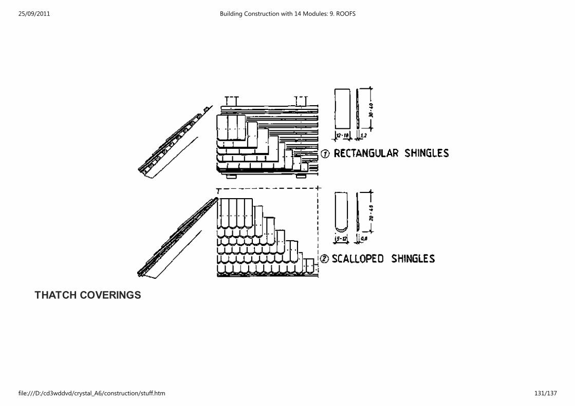
THATCH COVERINGS
25/09/2011 Building Construction with 14 Modules: 9. ROOFS
file:///D:/cd3wddvd/crystal_A6/construction/stuff.htm 131/137
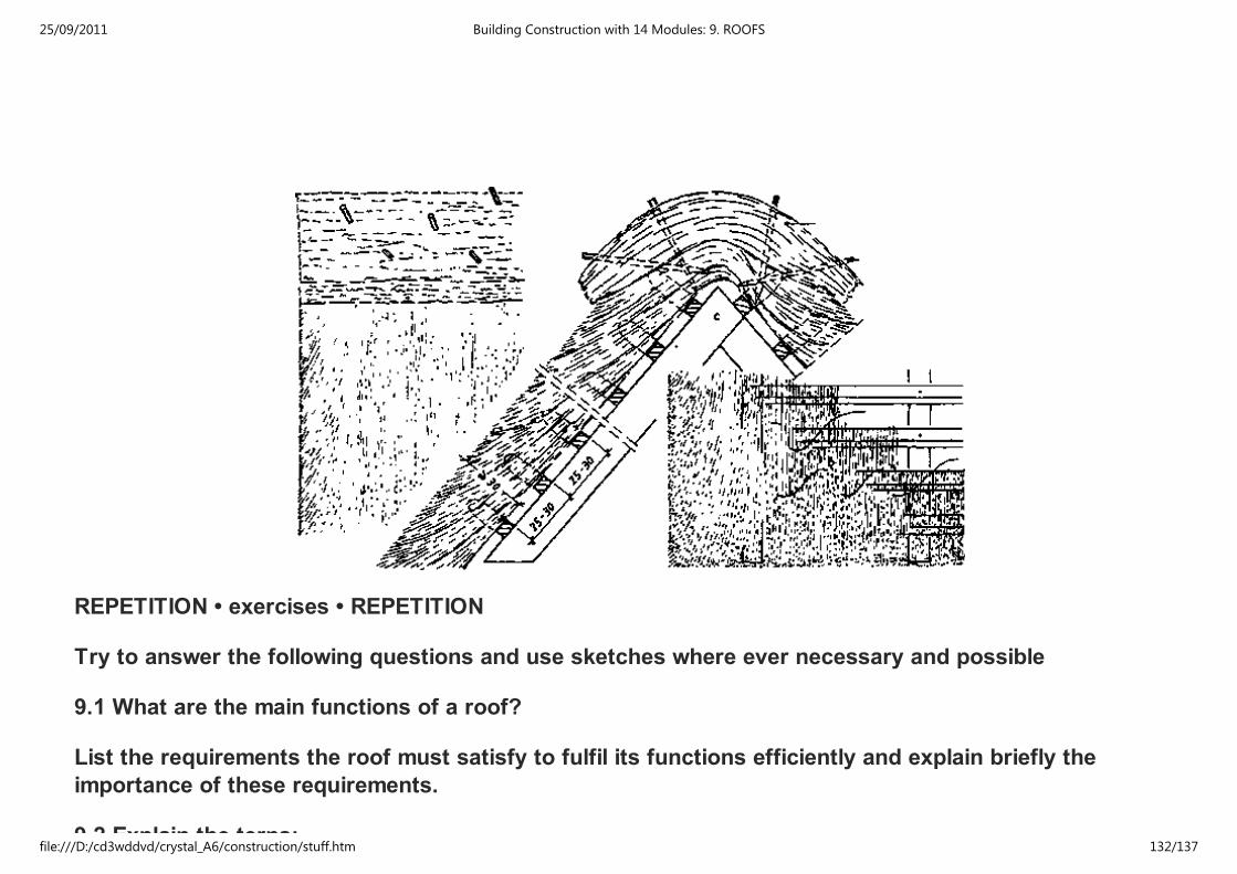
REPETITION • exercises • REPETITION
Try to answer the following questions and use sketches where ever necessary and possible
9.1 What are the main functions of a roof?
List the requirements the roof must satisfy to fulfil its functions efficiently and explain briefly the
importance of these requirements.
9.2 Explain the terns:
25/09/2011 Building Construction with 14 Modules: 9. ROOFS
file:///D:/cd3wddvd/crystal_A6/construction/stuff.htm 132/137
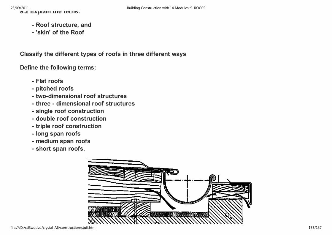
9.2 Explain the terns:
- Roof structure, and
- 'skin' of the Roof
Classify the different types of roofs in three different ways
Define the following terms:
- Flat roofs
- pitched roofs
- two-dimensional roof structures
- three - dimensional roof structures
- single roof construction
- double roof construction
- triple roof construction
- long span roofs
- medium span roofs
- short span roofs.
25/09/2011 Building Construction with 14 Modules: 9. ROOFS
file:///D:/cd3wddvd/crystal_A6/construction/stuff.htm 133/137

9.3 Write notes on Plat Roofs, explaining
- the structure of a flat roof
- thermal insulation materials
- single and double roof construction
- reinforced concrete flat roofs timber flat roofs
- parapet walls
and use sketches for illustration.
9.4 Write notes on Pitched Roofs, explaining
- the types of pitched roofs according to the shape of the roof
- the types of pitched roofs according to the structure of the roof
and use sketches for illustration.
Explain the following terms briefly:
- gable
- gable parapet
- verge
- hip
- hipped end
- vally
25/09/2011 Building Construction with 14 Modules: 9. ROOFS
file:///D:/cd3wddvd/crystal_A6/construction/stuff.htm 134/137
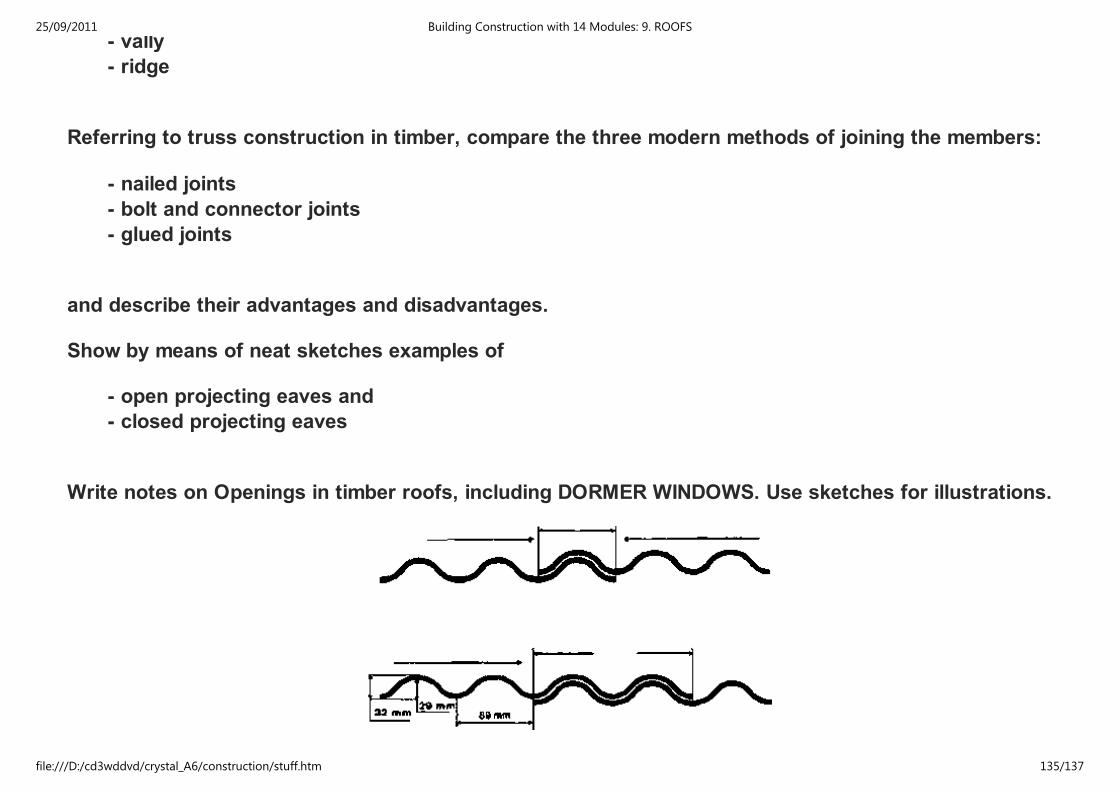
- vally
- ridge
Referring to truss construction in timber, compare the three modern methods of joining the members:
- nailed joints
- bolt and connector joints
- glued joints
and describe their advantages and disadvantages.
Show by means of neat sketches examples of
- open projecting eaves and
- closed projecting eaves
Write notes on Openings in timber roofs, including DORMER WINDOWS. Use sketches for illustrations.
25/09/2011 Building Construction with 14 Modules: 9. ROOFS
file:///D:/cd3wddvd/crystal_A6/construction/stuff.htm 135/137
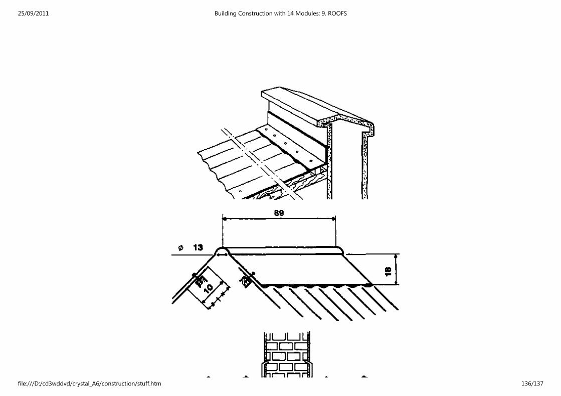
25/09/2011 Building Construction with 14 Modules: 9. ROOFS
file:///D:/cd3wddvd/crystal_A6/construction/stuff.htm 136/137
9.5 Classify the different types of roof coverings
What sort of covering materials may be used for the above listed types of roof coverings?
Explain - by means of sketches - different types of substructures depending on the 'skin' covering the
roof.
Write notes on the choice of roof coverings and explain in the form of a diagram the interdependency of
the pitch of the roof and the covering material.
Show - by using sketches for illustration - covering methods for different sorts of materials, such as:
- one -, two-, three-, layer table covering
- asbestos sheet covering
- covering with roofing tiles
- covering with slates
- covering with asbestos plain tiles
- covering with shingles
- thatch covering
- sheet metal covering
Please provide your feedback English | French | Spanish | German
25/09/2011 Building Construction with 14 Modules: 9. ROOFS
file:///D:/cd3wddvd/crystal_A6/construction/stuff.htm 137/137