Embed Size (px)
Citation preview

COST�Action�TU0904�Integrated�Fire�Engineering�and�Response�
WG1��Emidio�Nigro,�[email protected]�
WG2��Giuseppe�Cefarelli,�[email protected]�
WG3��Federico�Massimo�Mazzolani,�[email protected]��
Iolanda�Del�Prete,�[email protected]�
Anna�Ferraro,�[email protected]�
Gaetano�Manfredi,�[email protected]�
Domenico�Sannino,�[email protected]��
�
1�APPLICATION�OF�STRUCTURAL�FIRE�ENGINEERING�TO�THE�TOWERS�OF�THE�
COURTHOUSE�OF�NAPLES�
�
�
Summary�
Fire�Safety�Engineering�(FSE)�is�a�multi�discipline�aimed�to�define�the�fire�safety�strategy�for�buildings�in�fire�
situation,� in�which� structural� stability� and� control� of� fire� spread� are� achieved�by�providing� active� and/or�
passive�fire�protection�systems.�In�the�following�the�main�aspects�of�FSE�for�the�structural�safety�checks�in�
case�of�fire�(Structural�Fire�Engineering)�are�shown�with�reference�to�Italian�and�European�standards.�
FSE�requires�the�choice�of�performance�levels,�the�definition�of�design�fire�scenarios,�the�choice�of�
fire� models� and,� generally,� advanced� thermo�mechanical� analyses.� In� the� following� the� application� of�
Structural�Fire�Engineering�(namely�the�structural�behaviour�in�fire�situation)�to�the�existing�building�of�the�
New� Courthouse� of� Naples� will� be� described.� This� activity� is� still� in� progress;� nevertheless,� the� paper�
provides�enough�information�concerning�the�structural�characteristics�of�the�building,�the�choice�of�safety�
performance� levels,� the� active� and� passive� protection� systems� of� the� building,� the� identification� of� fire�
scenarios�through�Risk�Ranking�approach�and,�finally,�preliminary�thermal�and�structural�analyses.�
�
1.1�INTRODUCTION�
According�to�ISO/TR�13387�1,�the�“Fire�Safety�Engineering”�(FSE)�is�the�application�of�engineering�principles,�
rules�and�expert�judgement�based�on�a�scientific�assessment�of�the�fire�phenomena,�the�effects�of�fire�and�
both�the�reaction�and�behaviour�of�peoples,�in�order�to:�
- save�life,�protect�property�and�preserve�the�environment�and�heritage;�
- quantify�the�hazards�and�risks�of�fire�and�its�effects;�
- evaluate� analytically� the�optimum�protective� and�prevention�measures�necessary� to� limit,�within�
prescribed�levels,�the�consequences�of�fire.�
7

COST�Action�TU0904�Integrated�Fire�Engineering�and�Response�
Current� Italian� and� European� codes� (Ministry� of� Infrastructure� and�Transport,� 2008,� EN�1991�1�2�
and�EN�1992�1�2)�allow�the�use�of�a�performance�approach�through�the�concept�of�Fire�Safety�Engineering.�
The�temperature�distribution�within�the�elements�and�the�mechanical�and�geometric�nonlinear�structural�
response�are�taken�into�account�in�the�fire�performance�approach.�
The� Directive� 89/106/CEE� on� Construction� Products� of� the� European� Community� introduced� the�
definition�of�the�requirement�of�“safety�in�case�of�fire”�in�Europe,�which�is�the�base�for�the�application�of�
the� Fire� Safety� Engineering.� This� requirement,� implemented� in� the�National� Codes� of� European�member�
countries,�is�explained�by�achieving�the�following�five�objectives:�
- the�load�bearing�capacity�of�the�construction�can�be�assumed�for�a�specific�period�of�time;�
- the�generation�and�spread�of�both�fire�and�smoke�within�the�works�is�limited;�
- the�spread�of�fire�to�neighbouring�construction�works�must�be�limited;�
- occupants�have�to�be�able�to�leave�the�works�or�be�rescued�by�other�means;�
- the�safety�of�rescue�teams�must�be�taken�into�consideration.�
The�results�of�each�application�of�the�performance�approach�to�the�fire�safety�should�be�evaluated�
through�the�analysis�of�the�achievement�of�these�objectives.��
The�Fire�Safety�Engineering�allows�a�more�accurate�adjustment�of�the�safety�measures�at�specific�
risk� of� the� building� through� qualitative� and� quantitative� criteria� (namely� acceptance� criteria),� which� are�
agreed�with�the�building�approval�authority�and�hence�form�an�acceptable�starting�point�for�assessing�the�
safety�of�a�building�design.�
The�European�codes�for�structural�fire�safety�are�the�“Fire�Parts”�of�Structural�Eurocodes.�
In�Italy,�the�new�Technical�Code�for�Constructions�was�published�in�2008�(Ministry�of�Infrastructure�
and�Transport,� 2008).� For� the� first� time� in� Italy,� the� fire� action� is� introduced�within� the�definition�of� the�
actions�on�constructions,�as�an�“exceptional�load”.�The�document�defines�the�performance�safety�levels�of�
buildings� according� to� the� safety� objectives� required� by� the� Directive� 89/106/CEE� (Construction� Product�
Directive,� 1988).� The� Italian� Technical� Code� for� Constructions� defines� five� safety� performance� levels�
depending�on�the�importance�of�the�building,�which�establish�the�damage�level�that�can�be�accepted.�These�
rules�define�the�fire�structural�performance�requirements�and�they�refer�to�specific�technical�codes�issued�
by�the�Italian�Ministry�of�Interior�for�all�activities�under�the�control�of�the�National�Fire�Brigades�(Ministry�of�
Interior,� 2007a� and� Ministry� of� Interior,� 2007b).� The� regulations� are� basically� prescriptive� and� concern�
several�types�of�building�use.�However,�the�performance�based�fire�design�and�advanced�calculation�models�
may� be� applied� either� in� the� lack� of� prescriptive� rules� or� in� the� case� of� “derogation”� with� respect� to�
prescriptive�rules.�The�performance�based�design�(or�engineering�approach)�has�to�be�developed�according�
to�Decree�of� the�Ministry�of� the� Interior�of�09/05/2007� (Ministry�of� Interior,�2007b),� titled�“Direttive�per�
l’attuazione� all’approccio� ingegneristico� alla� sicurezza� antincendio”.� The� fire� design,� according� to� D.M.�
8

COST�Action�TU0904�Integrated�Fire�Engineering�and�Response�
09/05/2007,� summarized� in� Fig.� 1.1,� is� divided� in� two� stages:� the� first� one� is� preliminary� analysis,� i.e.�
qualitative�analysis,�while�the�second�one�is�quantitative�analysis.�Between�the�first�and�second�stage,�the�
approval�of�design�fire�scenarios�by�Italian�Fire�Brigades�(Vigili�del�Fuoco)�is�needed.�Finally,�it�is�important�
to�note�that�in�the�current�Italian�Codes�the�performance�based�approach�does�not�replace�the�prescriptive�
one,�but�both�the�approaches�coexist.�The�technical�solutions�imposed�by�the�prescriptive�approach�remain�
one�of�the�possible�ways�that�the�designer�may�choose�for�the�structural�fire�design.�
�
�(a)� (b)�
Fig.�1.1�Fire�Safety�Engineering:�Italian�code�process�according�to�Decree�of�the�Ministry�of�the�Interior�of�
09/05/2007�(Ministry�of�Interior,�2007b)�
�
1.2�CASE�STUDY:�TOWER�“A”�OF�THE�COURTHOUSE�OF�NAPLES��
In� the� following� the� application� of� Structural� Fire� Engineering� (namely� the� structural� behaviour� in� fire�
situation)�to�the�existing�building�of�the�New�Courthouse�of�Naples�is�described.�The�latter,�located�in�the�
administrative�centre�of�Naples�(Italy)�and�intended�for�office�use,�is�divided�into�three�main�areas,�namely�
Lot�1,�2�and�3,�built�on�a�reinforced�concrete�foundation�system�(located�at�11.45�m�above�the�sea�level).�In�
the�central�part�of�the�construction�(corresponding�to�the�Lot�2),�three�towers�of�different�heights�rise�from�
a�large�area�(named�“covered�square”)�situated�at�an�altitude�of�18.30�m�above�sea�level.�The�lower�tower�
Structural models
Design fire scenarios and fire models
Building description
Safety performance levels
Active and passive fire protections
Design static loads
Modify structural elements
Thermal and structural analyses (for each fire scenario)
YES
END
The model meets the fixed safety levels?
All design fire scenarios were
tested?
NO
YES
Modify active and/or
passive protec-tion systemNO
Project definition
Definition of fire safety goals
Definition of fire safety performance levels
Selection of design fire scenarios
STAGE I:Preliminary
Analysis
Choice of model
Analyses results
Selection of final design
Design documentation
STAGE II:Quantitative
Analysis
Approval of design fire scenarios by Italian Fire Brigade (Vigili del Fuoco)
9

COST�Action�TU0904�Integrated�Fire�Engineering�and�Response�
(Tower�C),� located�on� the�east� side,�extends� from�a�height�of�30.00�m�to�a�height�of�69.60�m�above�sea�
level;�the�intermediate�one�(Tower�B)�develops�from�a�height�of�30.00�m�to�a�height�of�89.40�m�above�sea�
level,�the�highest�one�(Tower�A)�extends�from�a�height�of�30.00�m�to�a�height�of�112.50�m�above�sea�level.�
The�Towers,�with�17,�23�and�29�storeys,�respectively,�are�characterised�by�reinforced�concrete�central�cores�
and,� from� 30.00�m� above� sea� level,� perimeter� steel� beams� and� columns.� These� latter� are� protected� by�
several�passive�protection�systems.��
In�the�following�the�attention�will�focus�only�on�the�highest�tower�(Tower�“A”).�
�
1.2.1�Building�description:�analysis�of�the�structural�characteristics�
The�Tower�A�is�101.00m�high�and�has�29�storeys�above�the�ground�(see�the�left�side�tower�in�Fig.�1.2).�The�
floor� can� be� divided� into� four� zones,� named� (see� Fig.� 1.3a):� 1)� Lamellare,� 2)� Emicicli� ,� 3)� Nucleo,� 4)�
Antinucleo.�In�particular�the�third�and�fourth�zone,�made�of�reinforced�concrete,�represent�the�bracing�and�
seism�resistant�structures�of�the�Tower�at�each�floor.�Other�stiffening�reinforced�concrete�structures�(Fig.�
1.3b)�are:�stairwells,�omega�wall�and�coupled�columns.�Until�30.00�m�above�sea�level�the�bracing�structures�
are�connected�to�a�reinforced�concrete�framed�structure,�having�large�beams�and�columns,�whereas,�from�
30.00�m�above� sea� level,� for� 25� storeys,� the�bracing� structures� are� connected� to� steel� frames�having� an�
interstorey�height�equal�to�3.30�m.�
�
Fig.�1.2�New�Courthouse�of�Naples:�South�side�view�
10
COST�Action�TU0904�Integrated�Fire�Engineering�and�Response�
Lamellare
Emicicli
Nucleo
Antinucleo
(a)�
r.c. walls
� wall�
Coupled columns
Nucleo
Antinucleo
BeamCoupled-beamsColumn
(b)�Fig.�1.3�New�Courthouse�of�Naples:�(a)�Floor�Map,�(b)�Structural�elements�
�
Referring�to�“emicicli”�zone�(see�Fig.�1.3a),�from�30.00�m�above�sea�level,�there�are�primary�steel�beams�
arranged� in�a� radial�pattern,�which� join� the�exterior� steel� columns� to� the�reinforced�concrete�wall�of� the�
“nucleo”�zone�or�to�the�coupled�beams�(which�join�the�“��wall“�to�the�“nucleo”�zone�wall,�see�Fig.�1.3a).��
All�members�are�connected�by�pinned�joints�as�shown�by�the�construction�details�reported�in�Fig.�1.4d,e,f.�
The�coupled�beams�with�IPE450�steel�profile�are�partially�encased�with�concrete�(see�Fig.�1.4a).�The�primary�
steel�beams,�arranged�in�a�radial�pattern,�are�also�partially�encased�with�concrete�and�have�several�cross�
section�dimensions�as�a� function�of� span� length.� In�particular,� there�are� four� types�of�cross�section,�with�
steel�profile�HEB�240,�HEB�260,�HEB�300�or�HEB�340� (see� for�example�Fig.�1.4c).� The� floor�deck,�with�an�
overall�depth�equal�to�220mm�and�superior�concrete�slab�equal�to�40mm,�are�reinforced�concrete�members�
with�lightweight�polystyrene�blocks.�The�secondary�beams�are�IPE�180�steel�profile.�The�steel�columns�are�
square� hollow� steel� section� 350x350mm2�with� thickness� varying� between� 10�mm� and� 20�mm� along� the�
height;�in�Tab.�1.1�the�columns�steel�section�along�the�height�are�summarized.�
�
a)�cross�section�of�coupled�beams� b)�cross�section�of�reinforced�concrete�slab�
c)�cross�section�of�primary�beam�and�longitudinal�section�of�reinforced�concrete�slab�
11

COST�Action�TU0904�Integrated�Fire�Engineering�and�Response�
d)�joint�between�primary�beam�and�coupled�beam� e)�joint�between�primary�beam�and�RC�wall�
f)�joint�between�steel�beam�and�steel�column�Fig.�1.4�Construction�details�
�
Tab.�1.1�Columns’�cross�sections�
Height�(m�above�sea�level)� � �
from� to� hollow�steel�section�mm�x�mm�x�mm�
Number�of�columns�
30.00� 39.90� 350x350x12.5� 8�350x350x16� 14�
39.90� 49.80� 350x350x12.5� 12�350x350x16� 10�
49.80� 59.70� 350x350x10� 10�350x350x12.5� 12�
59.70� 69.60� 350x350x10� 14�350x350x12.5� 8�
69.90� 112.50� 350x350x10� 22��
1.2.2�Choice�of�safety�performance�level�
In�the�case�study,�the�main�objective�of�fire�safety�checks�concerns�the�mechanical�resistance�and�stability,�
in�fire�situation,�of�the�tower.�In�agreement�with�the�Fire�Brigades�and�Owner,�the�safety�performance�level�
required� for� the�structure� is�assumed�as:�“maintaining�the� fire� resistance�requirements,�which�ensure� the�
lack�of�partial�and/or�complete�structural�collapse,�for�the�entire�duration�of�the�fire”.��
12

COST�Action�TU0904�Integrated�Fire�Engineering�and�Response�
In�addition,�with�reference�to�some�scenarios�(the�most�probable�fire�scenarios�which� involve�the�
effectiveness�of� active�protection� systems),� a� limited� structural�damage�after� the� fire�exposure�has�been�
also�required.�
�
1.2.3�Active�and�passive�fire�protection�systems�
The�tower� is�equipped�with�several�active�protection�systems:�fire�sprinkler�system,�fire�hydrants�and�fire�
extinguishers.�The�building� is�not�equipped�with�any�smoke�or�heat�evacuation�systems.�Each�floor�of�the�
tower�have�4�fire�exits�on�external�stairways�and�1�fire�exit�on�internal�separated�stairways�equipped�with�2�
fire�doors�REI�120.�Each�floor�can�be�divided�in�3�fire�compartments�(see�Fig.�1.5).�
Both�steel�beams�and�columns�are�protected�by�gypsum�boards.�
Fig.�1.5�Fire�Compartments�
�
1.2.4�Static�and�fire�design�load�calculation�
The� Italian�and�European�codes� (Ministry�of� Infrastructure�and�Transport,�2008�and�EN�1991�1�2)�classify�
the�fire�as�an�exceptional�load,�so�the�design�load�combination�in�fire�situation�is�defined�by:�
��
�����n
ikiikkdd QGGAF
1221 � (1)�
where�Gk1� is� the� characteristic� value�of� structural�permanent� load;�Gk2� is� the� characteristic� value�of�non�
structural�permanent�load;��2i�.�Qki�is�the�quasi�permanent�value�of�a�variable�action�i;�Ad�is�the�design�value�
of�the�exceptional�action�(fire).��
The� compartment’s� fire� load� density� is� closely� linked� to� actual� combustible� contents� of� the� building� or�
rooms�and,�therefore,�it�is�depending�on�the�building�or�room�occupancy.�In�the�case�study�the�value�of�fire�
13

COST�Action�TU0904�Integrated�Fire�Engineering�and�Response�
load�density� is�based�on�fire� load�classification�of�occupancies�provided�by�EN1991�1�2�(2004).�Therefore,�
according�to�office�use�for�the�building,�the�characteristic�fire�load�density�qf,k�[MJ/m²]�is�assumed�equal�to�
511MJ/m2�(80%�Fractile),�as�given�in�Table�E.4�of�EN�1991�1�2�(2004).��
�
1.2.5�Fire�Scenarios�and�fire�models�
The�design�fire�scenario�is�a�qualitative�description�of�the�fire�development�during�the�time,�identifying�key�
events�that�characterise�the�fire�and�differentiate�it�from�other�possible�fires.�It�typically�defines�the�ignition�
and�fire�growth�process,�the�fully�developed�stage,�decay�stage�together�with�the�building�environment�and�
systems�that�will�impact�on�the�course�of�the�fire.��
In�general,�the�number�of�distinguishable�fire�scenarios�is�too�large�to�permit�analysis�of�each�one.�
In�this�case�the�choice�of�the�design�fire�scenarios�is�carried�out�by�Fire�Risk�Assessment.�Really,�the�Fire�Risk�
Assessment�allows�to�individuate�scenario�structures�of�manageable�size�and�allows�to�make�the�case�that�
the�estimation�of�fire�risk�based�on�these�scenarios�is�a�reasonable�estimation�of�the�total�fire�risk�(0).�The�
Fire�Risk�Assessment�takes�into�account�the�consequence�and�likelihood�of�the�scenario.�Key�aspects�of�the�
process�are:�
- identification�of�a�comprehensive�set�of�possible�fire�scenarios;�
- estimation�of�probability�of�occurrence�of�each�fire�scenario;�
- estimation�of�the�consequence�of�each�fire�scenario;�
- estimation�of�the�risk�of�each�fire�scenario�(combination�of�the�probability�of�a�fire�and�a�quantified�
measure�of�its�consequence);�
- ranking�of�the�fire�scenarios�according�to�their�risk.�
The� Fire�Risk�Assessment� is� performed� through� the�event� tree�approach,� according� to� ISO�16732�
Guidelines.�A�fire�scenario� in�an�event�tree� is�given�by�a�time�sequence�path�from�the�initiating�condition�
through�a�succession�of� intervening�events�to�an�end�event.�Each�fire�scenario�corresponds�to�a�different�
branch�of�the�event�tree,�and�the�branches�collectively�comprise�or�represent�all�fire�scenarios.�
The�following�main�events,�that�may�affect�the�development�of�the�fire,�are�considered:�
- First�aid�suppression�
- Alarm�activation�(smoke�detectors)�
- Sprinkler�activation�
- Sprinkler�suppression�
- Barrier�effectiveness.�
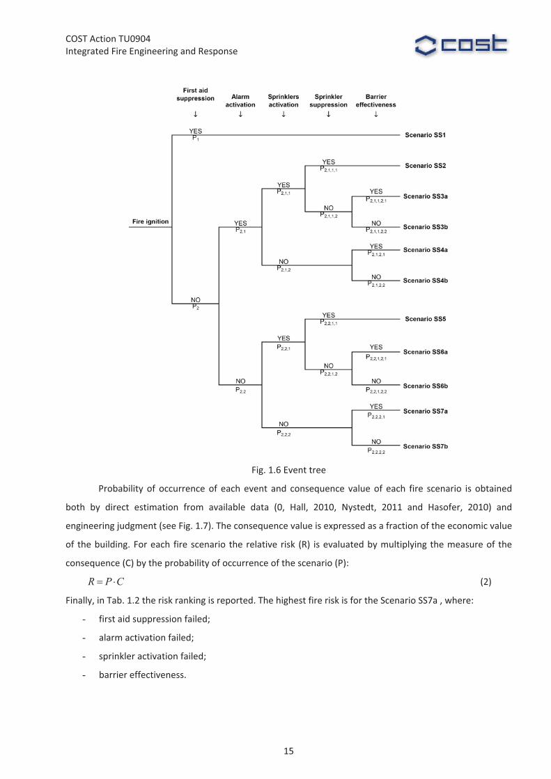
In�Fig.�1.6�the�event�tree�obtained�combining�the�main�events�is�reported.�
14
COST�Action�TU0904�Integrated�Fire�Engineering�and�Response�
�Fig.�1.6�Event�tree�
Probability� of� occurrence�of� each�event� and� consequence� value�of� each� fire� scenario� is� obtained�
both� by� direct� estimation� from� available� data� (0,� Hall,� 2010,� Nystedt,� 2011� and� Hasofer,� 2010)� and�
engineering�judgment�(see�Fig.�1.7).�The�consequence�value�is�expressed�as�a�fraction�of�the�economic�value�
of� the�building.�For�each� fire�scenario� the�relative�risk� (R)� is�evaluated�by�multiplying�the�measure�of� the�
consequence�(C)�by�the�probability�of�occurrence�of�the�scenario�(P):��
� �R P C (2)
Finally,�in�Tab.�1.2�the�risk�ranking�is�reported.�The�highest�fire�risk�is�for�the�Scenario�SS7a�,�where:�
- first�aid�suppression�failed;�
- alarm�activation�failed;�
- sprinkler�activation�failed;�
- barrier�effectiveness.�
15

COST�Action�TU0904�Integrated�Fire�Engineering�and�Response�
�Fig.�1.7�Event�tree�
�
Tab.�1.2�Risk�ranking�
�
16
COST�Action�TU0904�Integrated�Fire�Engineering�and�Response�
Therefore,�fire�scenario�SS7a�is�a�design�fire�scenario:�the�structure�is�required�to�“maintain�the�fire�
resistance�requirements,�which�ensure�the�lack�of�partial�and/or�complete�structural�collapse,�for�the�entire�
duration�of�the�fire”.�
Moreover,�another�design�fire�scenario�is�fire�scenario�SS5,�characterized�by�a�higher�probability�of�
occurrence,�for�which�limited�damages�are�allowed�for�the�structure.�
Finally,�also�the�following�secondary�events�can�be�significant:�
- doors�state�(open�or�closed);�
- windows�state�(open�or�closed).�
The�state�of�the�secondary�events�will�be�considered�inside�the�fire�model�as�well�as�the�location�of�
fire�ignition.�
The�post�flashover�fire�is�modelled�by�one�zone�model,�which�assumes�homogeneous�temperature,�
density,�internal�energy�and�pressure�of�the�gas�in�the�compartment.�
�
1.2.6�Substructure�identification�by�means�of�preliminary�analyses�
In� the� case� study,� due� to� the� building’s� large� size,� in� order� to� reduce� the� computational� time� the�
substructure�analysis� is�adopted,�according�to�Eurocode�suggestions.�Several�preliminary�analyses�allow�to�
define�the�substructures�limits�and�boundary�conditions.�The�aim�of�the�substructure�analysis�is�to�evaluate�
the�structural�fire�response�through�the�modelling�of�significant�parts�of�the�entire�structure.�The�designer�
has� the� responsibility� to� choose� the� substructure� in� such� a� way� that� the� hypotheses� on� the� constant�
boundary�conditions�are�reasonable�and�correspond�at�least�to�a�good�approximation�of�the�real�situation�
(Franssen,�2005).��
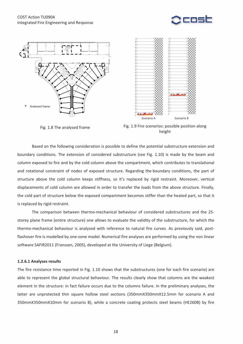
Preliminary�analyses�are�carried�out�on�a�25�storey�plane�frame�extracted�from�the�“Emicicli”�zone�
(Fig.� 1.9);� this� simplification� is� possible� because� the� RC� slab� is� designed� as� simply� supported� by� primary�
beams,�as�shown�in�Fig.�1.4c.�In�these�preliminary�analyses�the�structural�members�are�considered�without�
protection�systems.�The�analyzed�frame�has�been�chosen�in�order�to�analyze�structural�members�with�the�
maximum�degree� of� utilization� at� time� t� =� 0� (Ed,fi/Rd,fi,0).� All�members� (beam�column� and� beam�concrete�
wall)�are�connected�by�pinned�joints,�as�shown�by�the�construction�details�reported�in�Fig.�1.4�e,f.��
The� preliminary� analyses� are� carried� out� adopting� the� standard�time�temperature�curve�ISO834,�
with�the�only�purpose�of�defining�the�substructure,�which�should�represent�the�global�structural�behavior:�
really,� ISO834� curve� allows� a� direct� comparison� in� term� of� fire� resistance� time.� Two� fire� positions� are�
considered�(see�Fig.�1.9)�in�order�to�evaluate�possible�column’s�buckling�phenomenon�due�to�fire�scenarios�
localized�on�floors�in�which�there�is�the�change�section�of�the�columns.��
�
17
COST�Action�TU0904�Integrated�Fire�Engineering�and�Response�
Analysed frame
� Scenario�A� Scenario�B�
Fig.�1.8�The�analysed�frame� Fig.�1.9�Fire�scenarios:�possible�position�along�height�
�
Based�on�the�following�consideration�is�possible�to�define�the�potential�substructure�extension�and�
boundary� conditions.� The� extension�of� considered� substructure� (see� Fig.� 1.10)� is�made�by� the�beam�and�
column�exposed�to�fire�and�by�the�cold�column�above�the�compartment,�which�contributes�to�translational�
and� rotational� constraint� of� nodes� of� exposed� structure.� Regarding� the�boundary� conditions,� the� part� of�
structure� above� the� cold� column� keeps� stiffness,� so� it’s� replaced� by� rigid� restraint.� Moreover,� vertical�
displacements�of�cold�column�are�allowed�in�order�to�transfer�the�loads�from�the�above�structure.�Finally,�
the�cold�part�of�structure�below�the�exposed�compartment�becomes�stiffer�than�the�heated�part,�so�that�it�
is�replaced�by�rigid�restraint.�
The� comparison� between� thermo�mechanical� behaviour� of� considered� substructures� and� the� 25�
storey�plane�frame�(entire�structure)�one�allows�to�evaluate�the�validity�of�the�substructure,�for�which�the�
thermo�mechanical� behaviour� is� analysed�with� reference� to� natural� fire� curves.� As� previously� said,� post�
flashover�fire�is�modelled�by�one�zone�model.�Numerical�fire�analyses�are�performed�by�using�the�non�linear�
software�SAFIR2011�(Franssen,�2005),�developed�at�the�University�of�Liege�(Belgium).��
��
1.2.6.1�Analyses�results�
The�fire�resistance�time�reported�in�Fig.�1.10�shows�that�the�substructures�(one�for�each�fire�scenario)�are�
able� to� represent� the�global� structural�behaviour.�The� results�clearly� show�that�columns�are� the�weakest�
element�in�the�structure:�in�fact�failure�occurs�due�to�the�columns�failure.�In�the�preliminary�analyses,�the�
latter� are� unprotected� thin� square� hollow� steel� sections� (350mmX350mmX12.5mm� for� scenario� A� and�
350mmX350mmX10mm� for� scenario� B),� while� a� concrete� coating� protects� steel� beams� (HE260B)� by� fire�
18

COST�Action�TU0904�Integrated�Fire�Engineering�and�Response�
exposure.�Column,�loaded�with�constant�axial�force�during�fire�exposure,�fails�mainly�due�to�buckling,�that�
clearly�occurs�for�reduction�of�steel�stiffness�and�strength�produced�by�heating.�
�
� FIRE�SCENARIO�A:�+30.00�M� FIRE�SCENARIO�B:�+49.80�M�Global�structure�
30.00 m
1
1
�
49.80 m
2
1
2
�� 18�min� 16�min�
Substructure�
30.00 m
1
1
� 49.80 m
2
2
�
� 18�min� 16�min�Fig.�1.10�Analyses�results�
�
0
100
200
300
400
500
0 5 10 15 20Time [min]
Bending moment [kN m]
global structure-fire scenario A
global structure-fire scenario B
ResistanceStress
0
100
200
300
400
0 5 10 15 20Time [min]
Bending moment [kN m]
global structure
substructure
ResistanceStress
Fig.�1.11�Acting�bending�moment�and�Resistance�capacity�to�combined�compression�and�flexure�on�
the�heated�column�of�global�structure�–�comparison�between�fire�scenario�A�and�B.�
Fig.�1.12�Comparison�between�global�structure�and�substructure�results�–�Fire�scenario�B.�
�
Accordingly,� analyses� results� on� global� structure� (see� Fig.� 1.11)� show�that� the�minimum�
fire�resistance�occurs� when� fire�involves�the� thinnest� column� (fire� scenario� B).� Really,� the� latter� is�
characterized�by�a�section�factor�(Am/V)�bigger�than�thickest�column:�the�highest�section�factor�produces�a�
19

COST�Action�TU0904�Integrated�Fire�Engineering�and�Response�
fast� thermal�degradation�of� the� thinnest�column.�As�concerns� the�comparison�between�substructure�and�
global�structure�(see�Fig.�1.12),�approximately�the�same�time�of�collapse�is�attained,�because�the�stiffness�of�
beams�is�not�able�to�affect�the�axial�force�in�the�columns.��
�
1.2.7�Thermo�mechanical�analyses�with�reference�to�the�selected�fire�scenarios�
Subsequent� analyses� are� carried� out� on� substructure� characterized� by� the� thinnest� tubular� columns�
(350mmx350mmx10mm)� and� HE260B� beams� (partially� encased� with� concrete).� Both� steel� beams� and�
columns�are�protected�by�gypsum�boards.��
As�previously�said,�the�scenario�with�the�highest�risk�is�Scenario�SS7a�for�which:�
- first�aid�suppression�failed;�
- alarm�activation�failed;�
- sprinkler�activation�failed;�
- barrier�effectiveness.�
�
1.2.7.1�Fire�Scenario�SS7a���Fire�model�
Fire�curve�(see�Fig.�1.�14)�is�obtained�by�one�zone�model�(Cadorin,�2001).�Fig.�1.�13�shows�the�Rate�of�Heat�
Release�obtained�in�accordance�with�EN1991�1�2�(2004).�
0
0.5
1
1.5
2
2.5
3
3.5
4
4.5
5
0 10 20 30 40 50 60 70 80 90 100Time [min]
HRR (MW)
�
0100200300400500600700800900
100011001200
0 50 100 150 200 250 300Time [min]
Temperature [ C]
fire curve
column temperature
�
Fig.�1.�13�Rate�of�Heat�Release��
Fig.�1.�14�Comparison�between�fire�curve�and�column�temperature�
1.2.7.2�Fire�Scenario�SS7a���Structural�Behaviour�
Column’s� temperature� is� lower� than� 400°C� during� whole� fire� exposure� time,� as� shown� in� Fig.� 1.� 14.�
Therefore� combined� axial� and� bending� moment� resistance� is� approximately� constant� and� higher� than�
design�actions�(see�Fig.�1.�15).�
20

COST�Action�TU0904�Integrated�Fire�Engineering�and�Response�
-500
-400
-300
-200
-100
0
100
200
300
400
500
0 50 100 150 200 250 300
Time [min]
Bending Moment [kN m]
column bottom
column top
StressResistance
� -500
-400
-300
-200
-100
0
100
200
300
400
500
0 50 100 150 200 250 300
Time [min]
Normal stress (N/mm2)
column bottom
Stressyielding stress (fy)proportionality limit (fp)
�
Fig.�1.�15�Bending�moments�and��Resistance�capacity�to�combined�compression�and�flexure�on�
heated�column�
Fig.�1.�16�Comparison�between�normal�stress,�proportionality�limit�and�yielding�stress�in�heated�
column�
Comparison�between�normal� stress�and�yielding� stress,�during� fire�exposure� time,�shows� that�no�
significant�plastic� strains�occur� in� the�heated�column:�maximum�normal� stresses�are�slightly�greater� than�
proportionality�limit�between�100�min�and�180�min�(see�Fig.�1.�16).�Therefore�SS5�scenario’s�analysis�is�not�
significant:�in�fact,�in�this�fire�scenario�the�sprinkler�activation�extinguishes�the�fire�and�the�heat�release�rate�
decreases�to�zero�after�some�decreasing�time�(Staffansson,�2010),0��see�Fig.�1.17.�
0
0.5
1
1.5
2
2.5
3
3.5
4
4.5
5
0 25 50 75 100Time [min]
RHR (MW)
sprinkleractivation
Fig.�1.17�RHR�curves��
1.2.8�Future�developments�
The�activity�presented�above� is� still� in�progress.� In� future�the�fire�development�and� its�effects�on�the�
structure� will� be� evaluated� by� a� computational� fluid� dynamic� model� (i.e.� FDS� software),� used� to� solve�
numerically�the�partial�differential�equations�giving,�in�all�points�of�the�compartment,�the�thermo�dynamic�
and�aero�dynamic�variables.�
21

COST�Action�TU0904�Integrated�Fire�Engineering�and�Response�
The� structural� analyses� will� be� carried� out� by� several� non� linear� softwares� (SAFIR,� ABAQUS� and�
STRAUS7),�with�the�aim�of�performing�also�detailed�3D�thermo�mechanical�analyses.�
�
1.3�CONCLUSION�
This�paper� is�devoted�to� the�application�of�Structural�Fire�Engineering� (according� to� Italian�and�European�
Codes)� to�a�tower�of� the�Courthouse�of�Naples.�The�tower,�with�office�use,� is�101.00�m�high�and�has�29�
storeys� above� the� ground;� the� main� structure� is� realised� with� a� reinforced� concrete� central� core� and�
perimeter�steel�beams�and�columns.�
In� the� presented� case� study,� the� objective� of� fire� safety� assessment� concerns� the� mechanical�
resistance�and�stability�in�fire�situation�of�the�tower.�In�agreement�with�Fire�Brigade�and�building’s�Owner,�
the�performance�level�assumed�for�fire�safety�check�of�the�structure�is:�“maintaining�of�the�fire�resistance�
requirements,�which�ensure�the�lack�of�partial�and/or�complete�structural�collapse,�for�the�entire�duration�
of�the�fire”.�In�addition,�with�reference�to�the�most�probable�fire�scenarios,�which�involve�the�effectiveness�
of�active�protection�systems,�a�limited�structural�damage�after�the�fire�exposure�is�also�required.�
The�identification�of�design�fire�scenarios�is�carried�out�by�means�of�Fire�Risk�Assessment,�applying�
the�event�tree�approach�according�to� ISO�16732�Guidelines.�A� fire�scenario� in�an�event�tree� is�given�by�a�
time�sequence� path� from� the� initiating� condition� through� a� succession� of� intervening� events� to� an� end�
event.�Each�fire�scenario�corresponds�to�a�different�branch�of�the�event�tree,�and�the�branches�collectively�
comprise�or� represent�all� fire� scenarios.�The�main�events� taken� into�account� in� the� risk�assessment,� that�
may� affect� the� development� of� the� fire,� are:� first� aid� suppression;� alarm� activation� (smoke� detectors);�
sprinklers� activation;� sprinklers� suppression;� barrier� effectiveness.� Moreover,� the� following� secondary�
events� can� be� significant:� doors� state;� windows� state.� The� state� of� the� secondary� events� is� taken� into�
account�inside�the�fire�model�as�well�as�the�location�of�fire�ignition.�
The�post�flashover�fire�is�modelled�by�one�zone�model,�which�assumes�homogeneous�temperature,�
density,�internal�energy�and�pressure�of�the�gas�in�the�compartment,�applying�Ozone�software.��
In�order�to�evaluate�the�structural�fire�safety,�Italian�and�European�Codes�allow�the�global�structural�
analysis,� the�analysis�of�part�of�the�structure�(substructure�analysis)�and�the�analysis�of�a�member�(single�
member�analysis).�In�the�case�study,�due�to�the�building’s�large�size,�in�order�to�reduce�the�computational�
time,� the� substructure� analysis� is� adopted.� The� static� scheme� of� the� building� allows� to� define� simple�
substructures,� which� are� able� to� represent� the� global� structural� behaviour.� It� should� be� noted�that� the�
structural�static�scheme�doesn’t�produce�significant�indirect�actions�on�columns.�
The� results� of� the� structural� analyses� under� the� highest� risk� fire� scenario� (SS7a)� show� that� both�
column� and� beam’s� temperatures� are� lower� than� 400°C� during� fire� exposure� (see� Fig.� 1.� 14),� thanks� to�
passive� protection� systems:� therefore,� no� relevant� plastic� strains� occur� in� the� structure� (see� Fig.� 1.� 16).�
22

COST�Action�TU0904�Integrated�Fire�Engineering�and�Response�
Accordingly,�SS5�scenario’s�analysis� is�not�significant:� in� fact,� the�sprinkler�activation�extinguishes�the�fire�
and�the�heat�release�rate�decreases�to�zero�after�some�decreasing�time�(see�Fig.�1.17).�
�
References�ABAQUS�Standard/explicit�User’s�Manual� (2008),�Hibbit�Karlsson�and�Soresen,� Inc.�Vol�1�2�3,�Version�6.7,�
USA�2008.�
Construction�Product�Directive�(1988),�89/106/CEE,�Construction�of�European�Community,�December.�
EN�1991�1�2� (2002),�Eurocode�1.�Actions�on�structures� ��Part�1�2:�General�actions� ��actions�on�structures�exposed�to�fire,�November.�
EN�1992�1�2� (2004),�Eurocode�2.�Design�of�concrete�structures�–�Part�1�2:�General�Rules�–�Structural�Fire�Design.�March.�
EN�1993�1�2,�Eurocode�3.�Design�of�steel�structures���Part�1�2:�General�rules���Structural�fire�design,�April�2005.�
Franssen,� 2005:� Franssen� J.�M.,� SAFIR,� A� Thermal/Structural� Program� Modelling� Structures� under� Fire,�Engineering�Journal,�A.I.S.C.,�Vol�42,�No.�3�(2005),�143�158,�2005.�
Franssen,�Zaharia,�2005:�Franssen�J.M.,�Zaharia�R.,�Design�of�Steel�Structures�Subjected�to�Fire”,�Les�Èditions�de�l’Universitè�de�Liège,�2005.�
ISO/TR�13387�(1999),�Fire�safety�engineering.�
Ministry�of�Interior�(Italian�Government)�2007a.�Decree�09/03/2007,�Prestazioni�di�resistenza�al�fuoco�delle�costruzioni� nelle� attività� soggette� al� controllo� del� Corpo� nazionale� dei� vigili� del� fuoco.� GU� n.� 74� of�29/03/2007.�
Ministry� of� Interior� (Italian� Government)� 2007b.� Decree� 09/05/2007,� Direttive� per� l’attuazione�dell’approccio�ingegneristico�alla�sicurezza�antincendio.�GU�n.�117�of�22/05/2007.��
Ministry�of� Infrastructure�and�Transport�(Italian�Government)�2008.�Technical�Code�for�the�Constructions.�G.U.�n.�29�of�14/02/2008.�
ISO/DS�16732:�“Fire�safety�engineering�–�Guidance�on�fire�risk�assessment”,�Draft�2010.�
NFPA�(2003).�Operation�of�fire�Protection�Systems���a�Special�Edition�of�the�Fire�Protection�Handbook.�One�Batterymarch�Park,�Quincy,�Massachussets�02269�(2003).�
Hall,�2010:�Hall,�J.R.,�U.S.�Experience�with�Sprinklers�and�other�Fire�Extinguishing�Equipment,�Fire�Analysis�and�Research�Division�National�Fire�Protection�Association,�February�2010.�
Nystedt,�2011:�Nystedt�F.,�Verifying�Fire�Safety�Design� in�Sprinklered�Buildings,�Department�of�Fire�Safety�Engineering�and�Systems�Safety,�Lund�University,�Sweden,�Report�3150,�Lund�2011.�
Hasofer,�2007:�Hasofer�A.�M.,�Beck�V.�R.,�and�Bennetts�I.�D.,�Risk�Analysis�in�Building�Fire�Safety�Engineering,�Oxford:�Elsevier�Ltd.,�2007.�
Cadorin,�2001:�Cadorin� J.F.,� Franssen� J.M.,�and�Pintea�D.,�“The�design�Fire�Tool�Ozone�V2.2�–�Theoretical�Description� and�Validation� on� experimental� Fire� tests”,� Rapport� interne� SPEC/2001_01�University� of�Liege,�2001.��
Staffansson,�2010:�Staffansson�L.,�“Selecting�Design�Fire”,�Report�7032�Lund,�2010.�
23
COST�Action�TU0904�Integrated�Fire�Engineering�and�Response�
WG2��Ian�Burgess,�[email protected]��
�
2�HERON�TOWER,�LONDON�Arup�Fire�Ltd�
�
Summary�
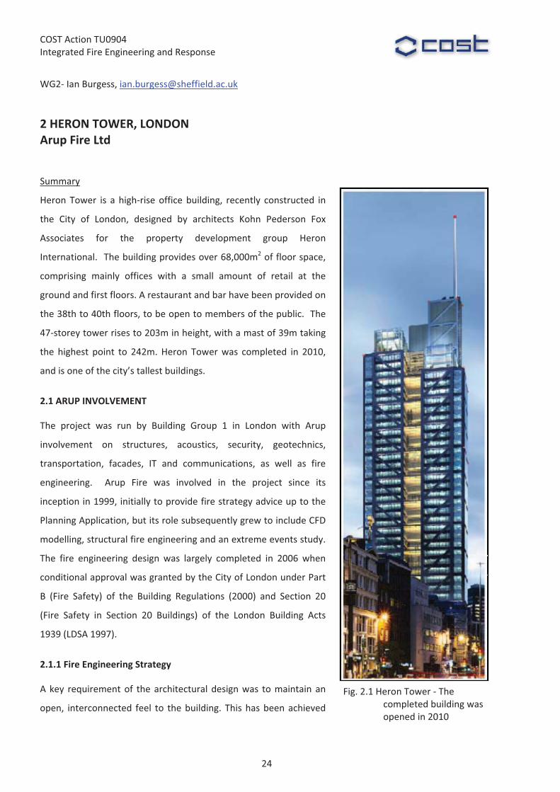
Heron�Tower� is� a�high�rise�office�building,� recently� constructed� in�
the� City� of� London,� designed� by� architects� Kohn� Pederson� Fox�
Associates� for� the� property� development� group� Heron�
International.� �The�building�provides�over�68,000m2�of�floor�space,�
comprising� mainly� offices� with� a� small� amount� of� retail� at� the�
ground�and�first�floors.�A�restaurant�and�bar�have�been�provided�on�
the�38th�to�40th�floors,�to�be�open�to�members�of�the�public.��The�
47�storey�tower�rises�to�203m�in�height,�with�a�mast�of�39m�taking�
the� highest� point� to� 242m.�Heron� Tower�was� completed� in� 2010,�
and�is�one�of�the�city’s�tallest�buildings.�
2.1�ARUP�INVOLVEMENT�
The� project� was� run� by� Building� Group� 1� in� London� with� Arup�
involvement� on� structures,� acoustics,� security,� geotechnics,�
transportation,� facades,� IT� and� communications,� as� well� as� fire�
engineering.� � Arup� Fire� was� involved� in� the� project� since� its�
inception�in�1999,�initially�to�provide�fire�strategy�advice�up�to�the�
Planning�Application,�but�its�role�subsequently�grew�to�include�CFD�
modelling,�structural�fire�engineering�and�an�extreme�events�study.��
The� fire� engineering� design� was� largely� completed� in� 2006� when�
conditional�approval�was�granted�by�the�City�of�London�under�Part�
B� (Fire� Safety)� of� the� Building� Regulations� (2000)� and� Section� 20�
(Fire� Safety� in� Section� 20� Buildings)� of� the� London� Building� Acts�
1939�(LDSA�1997).�
2.1.1�Fire�Engineering�Strategy��
A�key� requirement�of� the�architectural�design�was� to�maintain� an�
open,� interconnected� feel� to� the�building.� This�has�been�achieved�
Fig.�2.1�Heron�Tower���The�completed�building�was�opened�in�2010�
24
COST�Action�TU0904�Integrated�Fire�Engineering�and�Response�
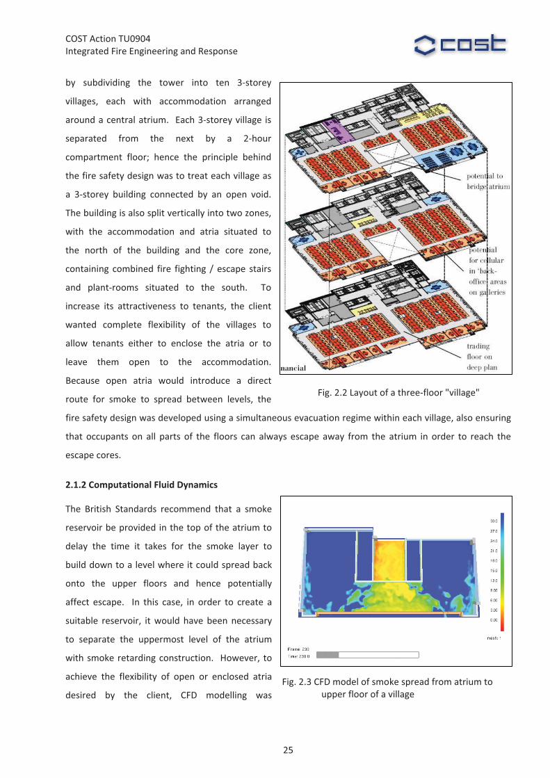
by� subdividing� the� tower� into� ten� 3�storey�
villages,� each� with� accommodation� arranged�
around�a�central�atrium.� �Each�3�storey�village� is�
separated� from� the� next� by� a� 2�hour�
compartment� floor;� hence� the� principle� behind�
the�fire�safety�design�was�to�treat�each�village�as�
a� 3�storey� building� connected� by� an� open� void.��
The�building�is�also�split�vertically�into�two�zones,�
with� the� accommodation� and� atria� situated� to�
the� north� of� the� building� and� the� core� zone,�
containing� combined� fire� fighting� /�escape� stairs�
and� plant�rooms� situated� to� the� south.� � To�
increase� its� attractiveness� to� tenants,� the� client�
wanted� complete� flexibility� of� the� villages� to�
allow� tenants� either� to� enclose� the� atria� or� to�
leave� them� open� to� the� accommodation.��
Because� open� atria� would� introduce� a� direct�
route� for� smoke� to� spread� between� levels,� the�
fire�safety�design�was�developed�using�a�simultaneous�evacuation�regime�within�each�village,�also�ensuring�
that� occupants� on� all� parts� of� the� floors� can� always� escape� away� from� the� atrium� in� order� to� reach� the�
escape�cores.�
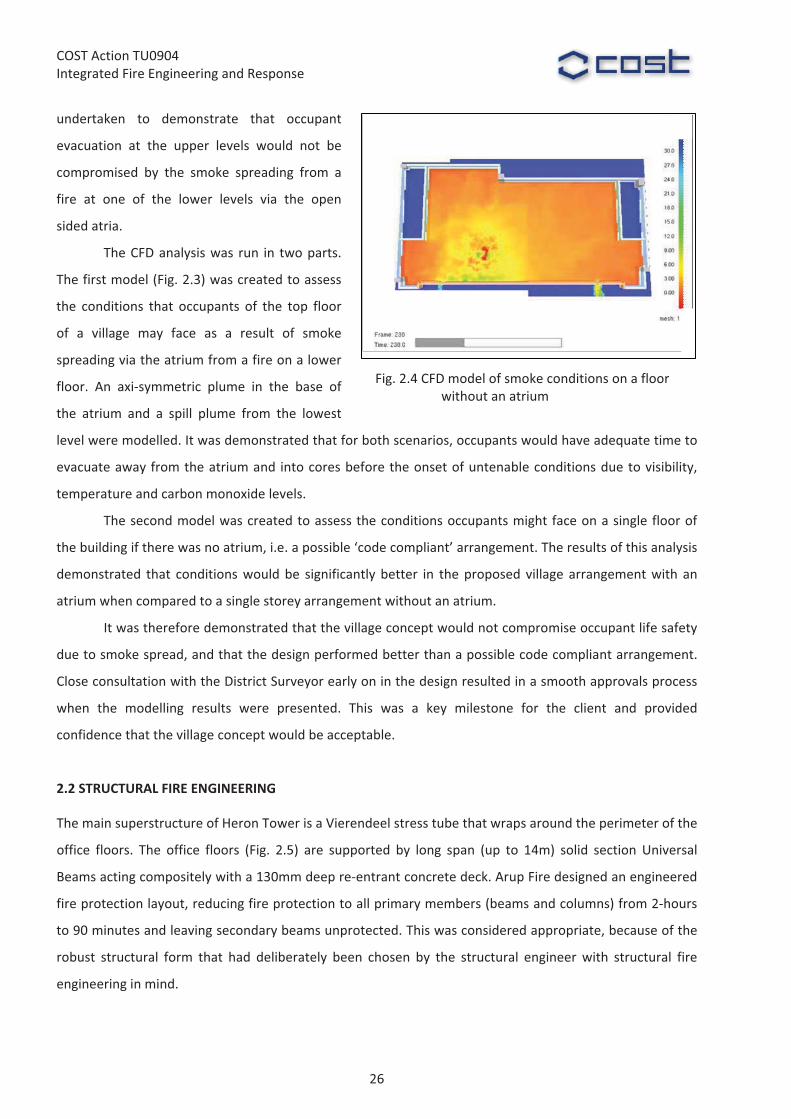
2.1.2�Computational�Fluid�Dynamics��
The� British� Standards� recommend� that� a� smoke�
reservoir�be�provided�in�the�top�of�the�atrium�to�
delay� the� time� it� takes� for� the� smoke� layer� to�
build�down�to�a�level�where�it�could�spread�back�
onto� the� upper� floors� and� hence� potentially�
affect� escape.� � In� this� case,� in� order� to� create� a�
suitable� reservoir,� it�would�have�been�necessary�
to� separate� the� uppermost� level� of� the� atrium�
with�smoke�retarding�construction.� �However,� to�
achieve� the� flexibility� of� open� or� enclosed� atria�
desired� by� the� client,� CFD� modelling� was�
Fig.�2.2�Layout�of�a�three�floor�"village"�
Fig.�2.3�CFD�model�of�smoke�spread�from�atrium�to�upper�floor�of�a�village�
25
COST�Action�TU0904�Integrated�Fire�Engineering�and�Response�
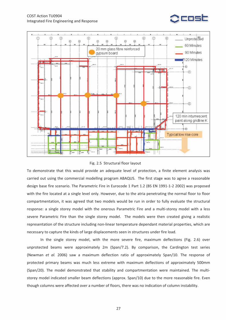
undertaken� to� demonstrate� that� occupant�
evacuation� at� the� upper� levels� would� not� be�
compromised� by� the� smoke� spreading� from� a�
fire� at� one� of� the� lower� levels� via� the� open�
sided�atria.��
The�CFD�analysis�was� run� in� two�parts.�
The�first�model�(Fig.�2.3)�was�created�to�assess�
the� conditions� that� occupants� of� the� top� floor�
of� a� village� may� face� as� a� result� of� smoke�
spreading�via�the�atrium�from�a�fire�on�a�lower�
floor.� An� axi�symmetric� plume� in� the� base� of�
the� atrium� and� a� spill� plume� from� the� lowest�
level�were�modelled.�It�was�demonstrated�that�for�both�scenarios,�occupants�would�have�adequate�time�to�
evacuate�away�from�the�atrium�and� into�cores�before�the�onset�of�untenable�conditions�due�to�visibility,�
temperature�and�carbon�monoxide�levels.�
The�second�model�was�created�to�assess�the�conditions�occupants�might�face�on�a�single�floor�of�
the�building�if�there�was�no�atrium,�i.e.�a�possible�‘code�compliant’�arrangement.�The�results�of�this�analysis�
demonstrated� that� conditions�would�be� significantly�better� in� the�proposed� village� arrangement�with� an�
atrium�when�compared�to�a�single�storey�arrangement�without�an�atrium.�
It�was�therefore�demonstrated�that�the�village�concept�would�not�compromise�occupant�life�safety�
due�to�smoke�spread,�and�that�the�design�performed�better�than�a�possible�code�compliant�arrangement.�
Close�consultation�with�the�District�Surveyor�early�on�in�the�design�resulted�in�a�smooth�approvals�process�
when� the� modelling� results� were� presented.� This� was� a� key� milestone� for� the� client� and� provided�
confidence�that�the�village�concept�would�be�acceptable.�
�
2.2�STRUCTURAL�FIRE�ENGINEERING�
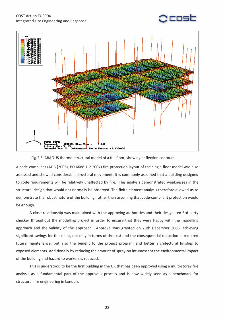
The�main�superstructure�of�Heron�Tower�is�a�Vierendeel�stress�tube�that�wraps�around�the�perimeter�of�the�
office� floors.� The� office� floors� (Fig.� 2.5)� are� supported� by� long� span� (up� to� 14m)� solid� section� Universal�
Beams�acting�compositely�with�a�130mm�deep�re�entrant�concrete�deck.�Arup�Fire�designed�an�engineered�
fire�protection�layout,�reducing�fire�protection�to�all�primary�members�(beams�and�columns)�from�2�hours�
to�90�minutes�and�leaving�secondary�beams�unprotected.�This�was�considered�appropriate,�because�of�the�
robust� structural� form� that� had� deliberately� been� chosen� by� the� structural� engineer�with� structural� fire�
engineering�in�mind.�
Fig.�2.4�CFD�model�of�smoke�conditions�on�a�floor�without�an�atrium�
26
COST�Action�TU0904�Integrated�Fire�Engineering�and�Response�
�To� demonstrate� that� this� would� provide� an� adequate� level� of� protection,� a� finite� element� analysis� was�
carried�out�using�the�commercial�modelling�program�ABAQUS.� �The�first�stage�was�to�agree�a�reasonable�
design�base�fire�scenario.�The�Parametric�Fire�in�Eurocode�1�Part�1.2�(BS�EN�1991�1�2�2002)�was�proposed�
with�the�fire�located�at�a�single�level�only.�However,�due�to�the�atria�penetrating�the�normal�floor�to�floor�
compartmentation,� it�was�agreed� that� two�models�would�be� run� in�order� to� fully�evaluate� the�structural�
response:� a� single� storey�model�with� the� onerous� Parametric� Fire� and� a�multi�storey�model�with� a� less�
severe� Parametric� Fire� than� the� single� storey� model.� � The� models� were� then� created� giving� a� realistic�
representation�of�the�structure�including�non�linear�temperature�dependant�material�properties,�which�are�
necessary�to�capture�the�kinds�of�large�displacements�seen�in�structures�under�fire�load.�
In� the� single� storey� model,� with� the� more� severe� fire,� maximum� deflections� (Fig.� 2.6)� over�
unprotected� beams� were� approximately� 2m� (Span/7.2).� By� comparison,� the� Cardington� test� series�
(Newman� et� al.� 2006)� saw� a� maximum� deflection� ratio� of� approximately� Span/10.� The� response� of�
protected� primary� beams� was� much� less� extreme� with� maximum� deflections� of� approximately� 500mm�
(Span/20).� The� model� demonstrated� that� stability� and� compartmentation� were� maintained.� The� multi�
storey�model�indicated�smaller�beam�deflections�(approx.�Span/10)�due�to�the�more�reasonable�fire.�Even�
though�columns�were�affected�over�a�number�of�floors,�there�was�no�indication�of�column�instability.�
Fig.�2.5��Structural�floor�layout
27
COST�Action�TU0904�Integrated�Fire�Engineering�and�Response�
A�code�compliant�(ADB�(2006),�PD�6688�1�2�2007)�fire�protection�layout�of�the�single�floor�model�was�also�
assessed�and�showed�considerable�structural�movement.�It�is�commonly�assumed�that�a�building�designed�
to�code�requirements�will�be�relatively�unaffected�by�fire.� �This�analysis�demonstrated�weaknesses� in�the�
structural�design�that�would�not�normally�be�observed.�The�finite�element�analysis�therefore�allowed�us�to�
demonstrate�the�robust�nature�of�the�building,�rather�than�assuming�that�code�compliant�protection�would�
be�enough.��
A�close�relationship�was�maintained�with�the�approving�authorities�and�their�designated�3rd�party�
checker� throughout� the�modelling� project� in� order� to� ensure� that� they� were� happy� with� the�modelling�
approach� and� the� validity� of� the� approach.� � Approval� was� granted� on� 29th� December� 2006,� achieving�
significant�savings�for�the�client,�not�only�in�terms�of�the�cost�and�the�consequential�reduction�in�required�
future� maintenance,� but� also� the� benefit� to� the� project� program� and� better� architectural� finishes� to�
exposed�elements.�Additionally�by�reducing�the�amount�of�spray�on�intumescent�the�environmental�impact�
of�the�building�and�hazard�to�workers�is�reduced.���
This�is�understood�to�be�the�first�building�in�the�UK�that�has�been�approved�using�a�multi�storey�fire�
analysis� as� a� fundamental� part� of� the� approvals� process� and� is� now� widely� seen� as� a� benchmark� for�
structural�fire�engineering�in�London.�
Fig.2.6��ABAQUS�thermo�structural�model�of�a�full�floor,�showing�deflection�contours�
28

COST�Action�TU0904�Integrated�Fire�Engineering�and�Response�
2.3�EXTREME�EVENTS�STUDY�
Fig.�2.7�Enhanced�sprinkler�system�layout�
Heron� Tower� originally� started� design� in� 1999�with� the� first� planning�
application�made�in�2000.�The�building�attracted�controversy�from�the�
outset� due� to� its� proximity� to� St� Paul's� Cathedral.� English� Heritage�
pressed�for�a�public�inquiry,�the�outcome�of�which�was�decided�by�the�
then�Deputy�Prime�Minister�John�Prescott.�The�tower�was�finally�given�
Planning�Approval� in� July�2002.� � In� the�delay�between� the�application�
being�made�and�consent�being�given,�the�security�situation�in�the�world�
shifted�due�to�the�September�11th�attacks�on�the�World�Trade�Centre.�
Suddenly,� fire� and� life� safety� in� tall� buildings� was� brought� to� the�
forefront�of�the�world’s�attention.�
A�threat�and�risk�assessment�was�carried�out�by�Arup�Security�
which� identified�a� fire�on�multiple� levels�as�a�credible�extreme�event.�
To� cope� with� this,� Arup� Fire� designed� the� sprinkler� system� with� a�
number� of� significant� enhancements.� Key� to� this� was� splitting� the�
system� into� two� separate� sub�systems,� with� each� sub�system� being�
served� by� a� separate� rising� main� serving� alternate� floors,� a� separate�
tank�with�an� infill� from�the�town�main�to� increase� the�capacity�of� the�
water�supply�and�separate�duty�standby�pumps.�
A� standard� sprinkler� system� (BS� EN� 12845� 2004� +� A2� 2009)�
would�be�designed�to�provide�water�flow�through�18�heads�for�a�period�
of�approximately�1�hour.�In�the�event�of�a�fire�on�more�than�one�floor,�
the�water�supply�would�be�exhausted�more�quickly,�possibly�before�the�
fire�brigade�had�been�able�to�access�the�building�to�fight�the�fire.���The�
enhanced�system�will�be�able�to�provide�water�for�at�least�1�hou�r�if�the�
fire�is�situated�over�two�levels,�and�for�longer�than�a�standard�system�if�
the�fire�is�situated�over�multiple�levels.�
�
The�two�separate�risers�have�also�been�
located� on� separate� sides� of� the�
building�thereby�reducing�the�potential�
for� an� external� attack� on� the� building�
to� completely� knock� out� the� sprinkler�
supply.��
29
COST�Action�TU0904�Integrated�Fire�Engineering�and�Response�
Hence� if� one� of� the� sprinkler� rising�mains� is� taken� out� of� action,� the� second�main� should� still� remain� in�
operation�to�supply�every�other�floor.��The�benefits�of�providing�an�enhanced�sprinkler�system�were�seen�
throughout�the�design,�with�relaxations�being�given�by�the�District�Surveyor�in�a�number�of�aspects�relating�
to�fire�safety�and�also�in�the�structural�fire�engineering�design.���
References�
ADB�(2006),�“Approved�Document�B���Fire�Safety,�2006�Edition”.�The�Stationery�Office�Ltd,�London,�UK.�BS� EN� 12845� (2004)� +� A2� (2009),� “Fixed� Firefighting� Systems.� Automatic� Sprinkler� Systems,� Design,�
Installation�And�Maintenance”,�British�Standards�Institution,�London,�UK.�BS�EN�1991�1�2�(2002),�“Eurocode�1:�Actions�on�Structures.�General�Actions.�Actions�on�Structures�Exposed�
to�Fire”,�British�Standards�Institution,�London,�UK.�Building�Regulations�(2000),�“The�Building�Regulations�for�England�and�Wales”,�The�Stationery�Office�Ltd,�
London,�UK.�LDSA�(1997),�“Fire�Safety�Guide�No�1���Section�20�Buildings”,�The�London�District�Surveyors’�Association.�Newman,�G.M.,�Robinson,� J.T.�and�Bailey�C.G.� (2006),�“Fire�Safe�Design:�A�New�Approach�to�Multi�Storey�
Steel�Framed�Buildings”,�SCI�Publication�P288,�Second�edition,�The�Steel�Construction�Institute,�UK.�PD�6688�1�2�(2007),�“Published�Document���Background�Paper�to�the�UK�National�Annex�to�BS�EN�1991�1�
2”,�British�Standards�Institution,�London,�UK.���
30
COST�Action�TU0904�Integrated�Fire�Engineering�and�Response�
WG2��Jochen�Zehfuß,�Peter�Schaumann,�Thomas�Kirsch,�[email protected]�hannover.de��
�
3�ADIDAS�LACES�
�
�
Summary�
The�new�adidas�headquarters,�called�‘Laces’,�has�been�opened�recently�in�Herzogenaurach,�Germany.�The�
building� consists� of� a� 5�storey� high� ring� of� office�modules,�which� are� surrounding� an� atrium.� For� a� slim�
appearance,�structural�members�of�the�building�have�been�left�unprotected�where�possible�and�coated�by�a�
thin�layer�of�intumescent�painting�where�necessary.�The�fire�resistance�has�been�verified�using�methods�of�
fire�engineering.�
Compartment�temperatures�have�been�calculated�using�the�zone�model�CFAST.� Input�parameters�
such� as� fire� load� and� compartment� dimensions� have� been� provided� by� the� architect.� As� an� important�
parameter,�the�opening�area�of�the�compartment�has�been�varied�in�a�parametric�study�to�determine�the�
relevant�fire�scenario.�This�fire�has�been�superimposed�with�a�local�fire�scenario.�
The� transient� temperature� fields� inside� structural� members� have� been� calculated� using� finite�
element� software.� Calculations�were�based�on� temperature�dependent�material� properties� for� steel� and�
intumescent�coating.�
The�smoke�exhaust�of�the�atrium�was�designed�using�the�CFD�simulation�FDS.�
�
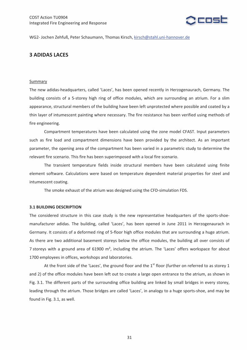
3.1�BUILDING�DESCRIPTION�
The� considered� structure� in� this� case� study� is� the� new� representative� headquarters� of� the� sports�shoe�
manufacturer� adidas.� The� building,� called� ‘Laces’,� has� been� opened� in� June� 2011� in� Herzogenaurach� in�
Germany.�It�consists�of�a�deformed�ring�of�5�floor�high�office�modules�that�are�surrounding�a�huge�atrium.�
As� there�are� two�additional�basement� storeys�below�the�office�modules,� the�building�all�over�consists�of�
7�storeys�with� a� ground� area� of� 61900�m²,� including� the� atrium.� The� ‘Laces’� offers�workspace� for� about�
1700�employees�in�offices,�workshops�and�laboratories.��
At�the�front�side�of�the�‘Laces’,�the�ground�floor�and�the�1st�floor�(further�on�referred�to�as�storey�1�
and�2)�of�the�office�modules�have�been�left�out�to�create�a�large�open�entrance�to�the�atrium,�as�shown�in�
Fig.�3.1.�The�different�parts�of� the�surrounding�office�building�are� linked�by�small�bridges� in�every�storey,�
leading�through�the�atrium.�Those�bridges�are�called�‘Laces’,�in�analogy�to�a�huge�sports�shoe,�and�may�be�
found�in�Fig.�3.1,�as�well.�
�
31
COST�Action�TU0904�Integrated�Fire�Engineering�and�Response�
Laces
Main�entrance
Atrium
�Fig.�3.1�Sketch�of�adidas�Laces��
�
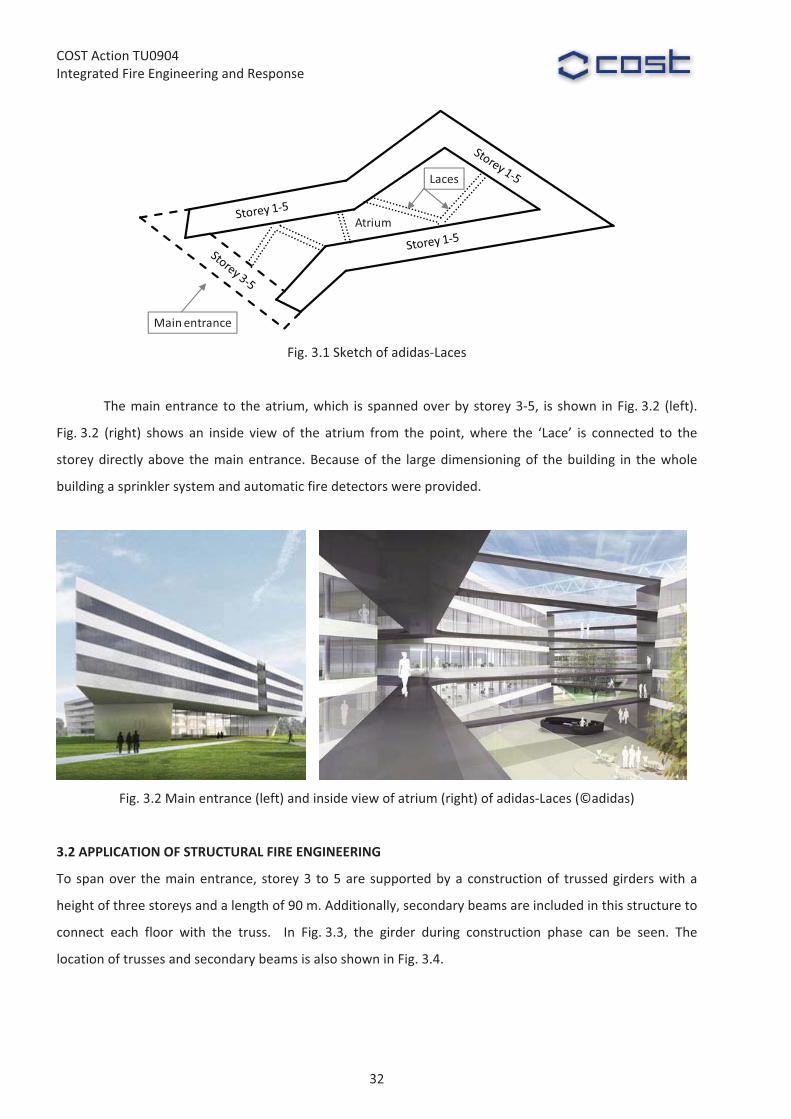
The�main�entrance� to� the�atrium,�which� is� spanned�over�by�storey�3�5,� is� shown� in�Fig.�3.2� (left).�
Fig.�3.2� (right)� shows� an� inside� view� of� the� atrium� from� the� point,�where� the� ‘Lace’� is� connected� to� the�
storey�directly�above� the�main�entrance.�Because�of� the� large�dimensioning�of� the�building� in� the�whole�
building�a�sprinkler�system�and�automatic�fire�detectors�were�provided.�
�
���� �Fig.�3.2�Main�entrance�(left)�and�inside�view�of�atrium�(right)�of�adidas�Laces�(©adidas)�
�
3.2�APPLICATION�OF�STRUCTURAL�FIRE�ENGINEERING�
To�span�over� the�main�entrance,� storey�3� to�5�are�supported�by�a�construction�of� trussed�girders�with�a�
height�of�three�storeys�and�a�length�of�90�m.�Additionally,�secondary�beams�are�included�in�this�structure�to�
connect� each� floor� with� the� truss.� � In� Fig.�3.3,� the� girder� during� construction� phase� can� be� seen.� The�
location�of�trusses�and�secondary�beams�is�also�shown�in�Fig.�3.4.�
32

COST�Action�TU0904�Integrated�Fire�Engineering�and�Response�
�Fig.�3.3�Truss�girder�spanning�over�main�entrance�during�construction�phase�(©hhpberlin)�
�
As�the�architect�aimed�at�a�slim�appearance�of�the�building,�it�was�asked�to�leave�the�steel�structure�
unprotected� if�possible�and�use� thin� layers�of� intumescent� coating� if� necessary.�A� fire� resistance� time�of�
90�minutes�had�to�be�proved�as�an�alternative�to�the�normative�requirement�of�an�R90�protection.�
Additionally,� it�was�asked�by�the�building�authority�to�prove�the�smoke�exhaust� inside�the�atrium�
taking�into�account�the�‘Laces’�leading�through�this�compartment.�
�
3.3�GENERAL�ASSESSMENT�STRATEGY�
As� it�was�allowed�by�the�building�authority�to�use�methods�of� fire�engineering,� the�concept� for� the� truss�
girder�was�as�follows.�First�the�fire�load�was�determined�according�to�EN�1991�1�2�for�office�buildings.�Using�
the�t²�method,�the�fire�was�simulated�in�a�zone�model�using�the�software�CFAST.�Additionally,�the�localised�
fire�calculation�according�to�EN�1991�1�2�Annex�C�was�used�to�find�the�critical�temperature.�To�be�on�the�
safe�side�the�sprinklers�are�not�considered�for�the�structural�fire�safety�design.�
Finally,� the� compartment� temperatures� were� used� as� thermal� action� in� several� thermal� finite�
element�simulations� including� steel� cross� sections� and� intumescent� coatings� to� predict� the� steel�
temperatures.� The� load� bearing� capacity� at� t=90�min� was� calculated� using� the� method� of� the� critical�
temperature� and�where� necessary� using�methods� of� simplified�mechanical� calculations,� all� according� to�
EN�1993�1�2.�
The�smoke�exhaust�was�proved�using�the�CFD�model�FDS.��
�
3.4�FIRE�SIMULATION�
3.4.1�Design�fire�
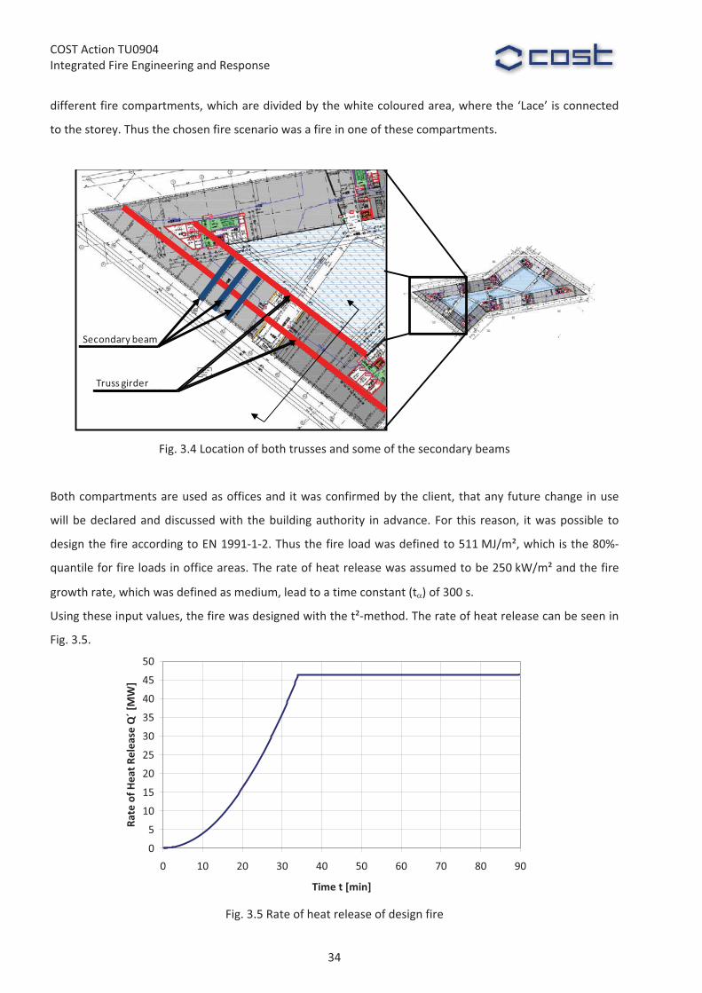
The�investigated�truss�girder�is�located�in�storey�3�to�5�above�the�entrance.�Fig.�3.4�shows�the�position�of�
the� truss� girder� and� some� of� the� secondary� beams.� As�may� be� seen,� the� truss� girders� are� crossing� two�
33
COST�Action�TU0904�Integrated�Fire�Engineering�and�Response�
different�fire�compartments,�which�are�divided�by�the�white�coloured�area,�where�the�‘Lace’�is�connected�
to�the�storey.�Thus�the�chosen�fire�scenario�was�a�fire�in�one�of�these�compartments.��
�
Fachwerkträger�
Secondary beam
Truss girder
�Fig.�3.4�Location�of�both�trusses�and�some�of�the�secondary�beams�
�
Both�compartments�are�used�as�offices�and�it�was�confirmed�by�the�client,�that�any�future�change�in�use�
will�be�declared�and�discussed�with� the�building�authority� in�advance.�For� this� reason,� it�was�possible� to�
design�the�fire�according�to�EN�1991�1�2.�Thus�the�fire�load�was�defined�to�511�MJ/m²,�which�is�the�80%�
quantile�for�fire�loads�in�office�areas.�The�rate�of�heat�release�was�assumed�to�be�250�kW/m²�and�the�fire�
growth�rate,�which�was�defined�as�medium,�lead�to�a�time�constant�(t)�of�300�s.�
Using�these�input�values,�the�fire�was�designed�with�the�t²�method.�The�rate�of�heat�release�can�be�seen�in�
Fig.�3.5.�
0
5
10
15
20
25
30
35
40
45
50
0 10 20 30 40 50 60 70 80 90
Time�t�[min]
Rate�of�H
eat�R
elease�Q´�[MW]
�Fig.�3.5�Rate�of�heat�release�of�design�fire�
34

COST�Action�TU0904�Integrated�Fire�Engineering�and�Response�
�3.4.2�Heat�transfer�analysis�
The�heat�transfer�analysis�has�been�conducted�combining�two�different�models.�First,�the�full�compartment�
fire� has� been� simulated� using� the� two�zone�model�software� CFAST.� The� geometrical� approximation� in�
CFAST� consists� of� three� connected� rectangular� compartments� called� C1_a,� C1_b� and� C1_c,� which� are�
defined� in� Fig.�3.6.� A� visualization� of� the� zone�model�compartments,� including� window� areas� and�
compartment�connections�(magenta),�is�shown�in�Fig.�3.7.��
��
C1_a
C1_b C1_c
�Fig.�3.6�Definition�of�compartments�for�multi�room�zone�model�analysis�
C1_aC1_b
C1_c
�Fig.�3.7�Visualization�of�compartments�in�multi�room�zone�model�analysis�with�CFAST�
�
A�critical�parameter�for�the�results�of�such�calculations�is�the�area�of�ventilation�openings.�As�it� is�
not�possible� to� foresee,� if�and�when�a�window� is�partially�or� fully�opened�or�destroyed�during�a� fire,� the�
most�critical�opening�area�has�to�be�defined.�For�the�reason�that�it� is�also�not�possible�to�foresee�if�more�
ventilation� openings� increase� or� decrease� compartment� temperatures,� a� parametric� study� has� been�
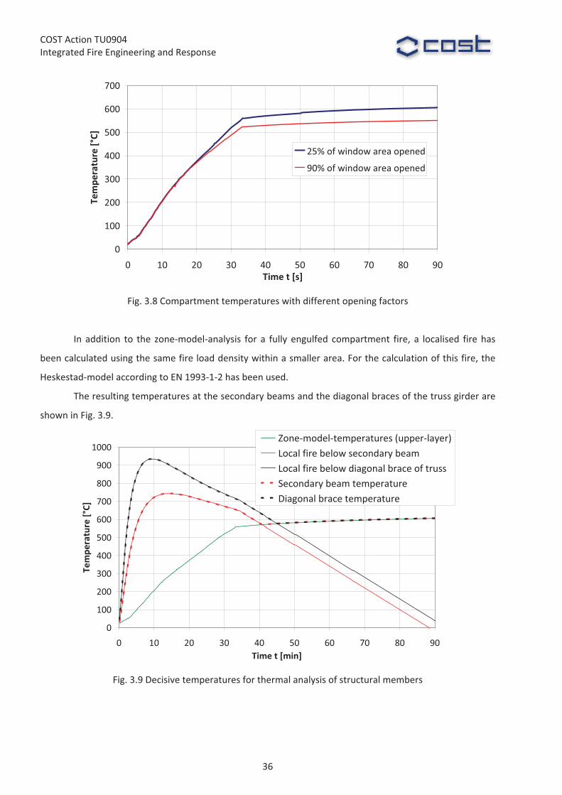
conducted.� Fig.�3.8� shows� the� compartment� temperatures� using� the� minimum� and� maximum� opening�
factor,�which�is�defined�as�25%�and�90%�of�the�whole�window�area.�
35
COST�Action�TU0904�Integrated�Fire�Engineering�and�Response�
0
100
200
300
400
500
600
700
0 10 20 30 40 50 60 70 80 90Time�t�[s]
Tempe
rature�[°C]
25%�of�window�area�opened
90%�of�window�area�opened
�Fig.�3.8�Compartment�temperatures�with�different�opening�factors�
�
In� addition� to� the� zone�model�analysis� for� a� fully� engulfed� compartment� fire,� a� localised� fire�has�
been�calculated�using�the�same�fire�load�density�within�a�smaller�area.�For�the�calculation�of�this�fire,�the�
Heskestad�model�according�to�EN�1993�1�2�has�been�used.��
The�resulting�temperatures�at�the�secondary�beams�and�the�diagonal�braces�of�the�truss�girder�are�
shown�in�Fig.�3.9.�
0
100
200
300
400
500
600
700
800
900
1000
0 10 20 30 40 50 60 70 80 90Time�t�[min]
Tempe
rature�[°C]
Zone�model�temperatures�(upper�layer)Local�fire�below�secondary�beamLocal�fire�below�diagonal�brace�of�trussSecondary�beam�temperatureDiagonal�brace�temperature
�Fig.�3.9�Decisive�temperatures�for�thermal�analysis�of�structural�members�
�
36

COST�Action�TU0904�Integrated�Fire�Engineering�and�Response�
It�can�be�seen,�that�the�temperatures�calculated�by�the�local�fire�model�are�decisive�during�the�first�
40�min�in�fire,�while�the�temperatures�calculated�with�CFAST�are�higher�afterwards.�
It�has�to�be�mentioned,�that�the�shown�curves�for�local�fire�temperatures�have�not�been�used�for�all�
parts�of�the�thermal�calculation�of�the�structural�members.�When�the�flame�height�is�reaching�the�different�
members,� the� thermal� loading� for� them� has� to� be� calculated� using� the� heat� flux� from� fire� to�member,�
instead�of�calculating�the�air�temperatures.�This�leads�to�a�higher�thermal�loading�and�thus�has�been�taken�
into�account�for�the�thermal�calculation�of�the�structural�members.�As�it�is�not�feasible�to�combine�heat�flux�
and�gas�temperatures�in�one�diagram,�this�is�not�shown�here.�
�
3.5�THERMAL�RESPONSE�OF�STRUCTURE�
The� structural� temperatures� have� been� calculated� by� hhpberlin� using� ANSYS.� The� double�check� was�
conducted� by� the� Institute� for� Steel� Construction� using� BoFire.� For� both� calculations,� the� same� thermal�
material�properties�have�been�used.�The�material�steel�was�implemented�using�thermal�conductivity,�heat�
capacity� and� density� according� to� EN� 1993�1�2.� For� the� thermal� simulation� of� the� intumescent� coating,�
material� properties� according� to� Dorn,� 2003� have� been� used,� as� there� are� no� normative� regulations�
available.� However,� as� the� values� have� been� proofed� against� experimental� tests,� they� can� be� used� in� a�
particular� range.� In� Fig.� 3.10,� the� temperature� dependent�material� properties� are� defined� in� relation� to�
their�values�at�room�temperature�(20°C).�
0
1
2
3
4
5
6
7
8
9
10
0 200 400 600 800 1000 1200Temperature�[°C]
Relativ
e�values�of�the
rmal�con
ductan
ce,�
density
�and
�heat�cap
acity
�[�]
cp()/cp,20�;��[cp,20 =433�J/kgK]
�()/�20�;��[�20�=18�W/mK]
�()/�20�;��[�20 =1.8�Mg/m³]
�Fig.�3.10�Material�properties�for�intumescent�coatings�according�to�Dorn,�2003�
�
37
COST�Action�TU0904�Integrated�Fire�Engineering�and�Response�
In� Fig.�3.10� it� can� be� seen,� that� the� thermal� conductivity� �()� is� increasing� at� a� temperature� of�
450°C.� This� steep� increase� has� been�manually� implemented� by� Dorn,� 2003� to� cover� the� case� of� a� local�
redemption�of�the�intumescent�coating.�
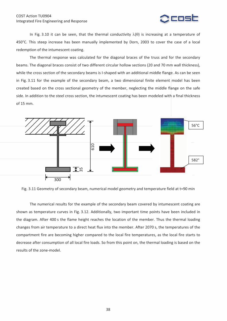
The� thermal� response�was� calculated� for� the�diagonal� braces� of� the� truss� and� for� the� secondary�
beams.�The�diagonal�braces�consist�of�two�different�circular�hollow�sections�(20�and�70�mm�wall�thickness),�
while�the�cross�section�of�the�secondary�beams�is�I�shaped�with�an�additional�middle�flange.�As�can�be�seen�
in� Fig.�3.11� for� the� example� of� the� secondary� beam,� a� two� dimensional� finite� element�model� has� been�
created�based�on� the�cross� sectional�geometry�of� the�member,�neglecting� the�middle� flange�on� the�safe�
side.�In�addition�to�the�steel�cross�section,�the�intumescent�coating�has�been�modeled�with�a�final�thickness�
of�15�mm.��
�
300
610
35
Fig.�3.11�Geometry�of�secondary�beam,�numerical�model�geometry�and�temperature�field�at�t=90�min�
�
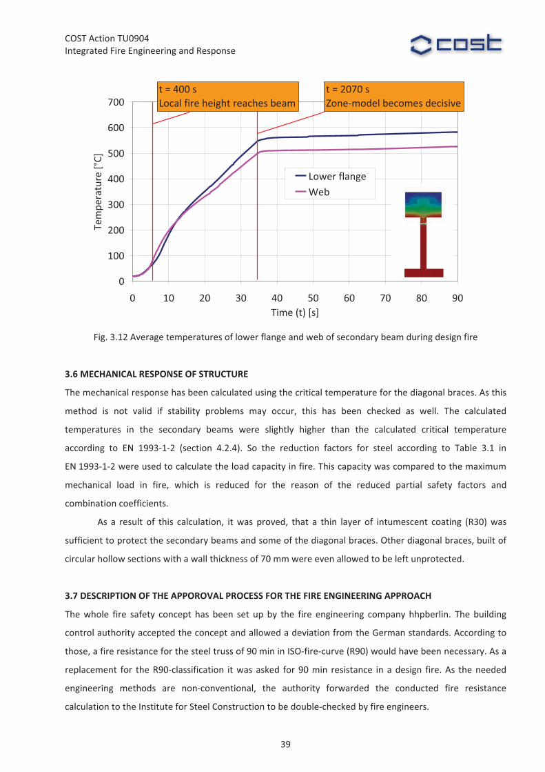
The�numerical�results�for�the�example�of�the�secondary�beam�covered�by�intumescent�coating�are�
shown�as� temperature�curves� in�Fig.�3.12.�Additionally,� two� important� time�points�have�been� included� in�
the�diagram.�After�400�s� the� flame�height� reaches� the� location�of� the�member.�Thus� the� thermal� loading�
changes�from�air�temperature�to�a�direct�heat�flux�into�the�member.�After�2070�s,�the�temperatures�of�the�
compartment�fire�are�becoming�higher�compared�to�the�local�fire�temperatures,�as�the�local�fire�starts�to�
decrease�after�consumption�of�all�local�fire�loads.�So�from�this�point�on,�the�thermal�loading�is�based�on�the�
results�of�the�zone�model.�
582°
56°C
38
COST�Action�TU0904�Integrated�Fire�Engineering�and�Response�
0
100
200
300
400
500
600
700
0 10 20 30 40 50 60 70 80 90Time�(t)�[s]
Temperature�[°C]
Lower�flangeWeb
t�=�2070�sZone�model�becomes�decisive
t�=�400�sLocal�fire�height�reaches�beam
�Fig.�3.12�Average�temperatures�of�lower�flange�and�web�of�secondary�beam�during�design�fire�
�
3.6�MECHANICAL�RESPONSE�OF�STRUCTURE��
The�mechanical�response�has�been�calculated�using�the�critical�temperature�for�the�diagonal�braces.�As�this�
method� is� not� valid� if� stability� problems� may� occur,� this� has� been� checked� as� well.� The� calculated�
temperatures� in� the� secondary� beams� were� slightly� higher� than� the� calculated� critical� temperature�
according� to� EN� 1993�1�2� (section� 4.2.4).� So� the� reduction� factors� for� steel� according� to� Table� 3.1� in�
EN�1993�1�2�were�used�to�calculate�the�load�capacity�in�fire.�This�capacity�was�compared�to�the�maximum�
mechanical� load� in� fire,� which� is� reduced� for� the� reason� of� the� reduced� partial� safety� factors� and�
combination�coefficients.�
As� a� result� of� this� calculation,� it�was� proved,� that� a� thin� layer� of� intumescent� coating� (R30)�was�
sufficient�to�protect�the�secondary�beams�and�some�of�the�diagonal�braces.�Other�diagonal�braces,�built�of�
circular�hollow�sections�with�a�wall�thickness�of�70�mm�were�even�allowed�to�be�left�unprotected.�
��
3.7�DESCRIPTION�OF�THE�APPOROVAL�PROCESS�FOR�THE�FIRE�ENGINEERING�APPROACH��
The�whole� fire� safety� concept� has� been� set� up� by� the� fire� engineering� company�hhpberlin.� The� building�
control�authority�accepted�the�concept�and�allowed�a�deviation�from�the�German�standards.�According�to�
those,�a�fire�resistance�for�the�steel�truss�of�90�min�in�ISO�fire�curve�(R90)�would�have�been�necessary.�As�a�
replacement� for� the�R90�classification� it�was�asked� for�90�min� resistance� in�a�design� fire.�As� the�needed�
engineering� methods� are� non�conventional,� the� authority� forwarded� the� conducted� fire� resistance�
calculation�to�the�Institute�for�Steel�Construction�to�be�double�checked�by�fire�engineers.��
39

COST�Action�TU0904�Integrated�Fire�Engineering�and�Response�
3.8�SUMMARY�AND�CONCLUSIONS�
The� fire� resistance� of� a� truss� girder� and� additional� secondary� beams� inside� the� adidas�headquarter� has�
been�calculated�using�methods�of� fire�engineering.� The� fire�has�been�calculated�using�a� two�zone�model�
and� a� standardised� method� to� calculate� local� fire� temperatures.� The� calculated� air� temperatures� and�
partially� the� heat� flux� from� local� fire� have� been� used� as� thermal� load� for� a� thermal� finite� element�
calculation� to� determine� the� steel� temperatures.� This� finite� element� analysis� included� an� intumescent�
coating,� which� was� used� to� protect� the� steel� parts.� Finally,� the� calculated� temperatures� were� used� to�
determine�the�load�capacity�after�90�min�in�design�fire.��
It� was� proved� that� circular� hollow� sections�with� a�wall� thickness� of� 70�mm�were� able� to� be� left�
without� any� fire� protection.� Thinner� hollow� sections� and� all� secondary� beams� had� to� be� protected�with�
intumescent� coating� for� fire� resistance� class� R30.� Summing� up,� because� of� the� use� of� fire� engineering�
methods,�it�was�possible�to�keep�the�slim�appearance�of�the�construction�instead�of�hiding�it�behind�thick�
layers�of�plaster�board.��
�
Acknowledgements��
The�authors�would�like�to�thank�adidas�for�the�permission�to�publish�this�case�study.��
�
References�
CFAST,�Jones,�W.�W.,�NIST,�2002,�available�at:��http://cfast.nist.gov/��DIN�V� ENV� 1991�1�2� –� Eurocode� 1� –� Einwirkungen� auf� Tragwerke� –� Teil� 1�2:� Allgemeine� Einwirkungen� –�
Brandeinwirkungen�auf�Tragwerke,�German�Version�of�Eurocode�1:�Actions�on�structures�–�Part�1�2:�General�actions�–�Actions�on�structures�exposed�to�fire,�Beuth�Verlag,�September�2003�
DIN� V� ENV� 1993�1�2,� 1997:� Eurocode� 3� –� Bemessung� und� Konstruktion� von� Stahlbauten� –� Teil� 1�2:�Allgemeine�Regeln�–�Tragwerksbemessung�für�den�Brandfall,�German�version�of�Eurocode�3:�Design�of�steel�structures�–�Part�1�2:�General�rules�–�Structural�fire�design,�Beuth�Verlag,�Mai�1997�
ANSYS,�CADFEM�GmbH,�2010,�available�at:�www.cadfem.de/ansys��BoFire,� Schaumann,� P.,� Upmeyer,� J.,� Kettner,� F.,� Universität� Hannover,� 2004,� http://www.stahlbau.uni�
hannover.de/244.html�Dorn,� 2003:�Numerical� simulation� of� the� effect� of� intumescent� coatings� on� fire� resistance� calculation� of�
steel� members,� German� title:� Rechnerische� Simulation� der� Wirkung� dämmschichtbildender�Beschichtungen�bei�der�brandschutztechnischen�Auslegung�von�Stahlbauteilen,�in:�Festschrift�zum�60.�Geburtstag�von�Univ.�Prof.�Dr.�Ing.�D.�Hosser,�Heft�173�of�iBMB,�TU�Braunschweig.�
General�information�on�adidas�Laces:�� http://www.adidas�group.com/de/pressroom/archive/2011/10June2011.aspx�
40

COST�Action�TU0904�Integrated�Fire�Engineering�and�Response�
WG2��Ian�Burgess,�[email protected]��
�
4�THE�PINNACLE,�LONDON�Arup�Fire�Ltd�
�
Summary�
The�project�is�a�63�storey�office�building�known�as�The�
Pinnacle,� proposed� to� be� built� in� the�City� of� London.�
The� building� is� designed� by� KPF� architects.� The�
building�profile�tapers�linearly�with�height�up�to�Level�
44,�where�the�floor�plates�then�cut�back�sequentially,�
forming�a�spinal�wrap�profile.�The�building�has�a�highly�
irregular�floor�plate�and�a�beam�layout�which�changes�
from� floor� to� floor.� Standing� at� 288m� high,� The�
Pinnacle�will�be�one�of�the�tallest�buildings�in�the�City�
of�London.��The�building�is�scheduled�to�be�completed�
in�2014.�
�
4.1�INTRODUCTION�
Structural� fire� analyses�were� performed�by�Arup� Fire�
to�develop�an�engineered� fire�protection� strategy� for�
the� structural� steel� members� of� the� building� and� to�
assess�the�robustness�of�the�building�in�a�fire.�
An� engineered� structural� fire� protection�
strategy� featuring� unprotected� beams� and� reduced�
fire� rating� was� proposed,� rather� than� relying� on� the�
prescriptive�guidance�defined�by�Building�Regulations.�
Non�linear�finite�element�analyses�were�carried�out�using�the�ABAQUS�program�by�the�structural�fire�team�
in�London.��There�were�several�challenges�in�undertaking�the�structural�fire�analysis�due�to�the�shape�and�
structural�form�of�the�building.�
The�organic� shape�of� the� floor�plate�meant� that� the�beams�had� to�be�arranged� in�a�highly� irregular�
layout.�
The� architects� expressed� their� desire� to� have� large,� clear� spans� with� minimum� number� of� internal�
columns�to�provide�flexibility�for�the�building�tenants.�
Fig.�4.1�The�Pinnacle�as�part�of�the�City�of�London�skyline���visualization�
41
COST�Action�TU0904�Integrated�Fire�Engineering�and�Response�
The� architects� also�wanted� the� perimeter� columns� to� have� a� circular� cross�sectional� profile.� � These�
perimeter�columns�formed�part�of�the�lateral�load�resisting�system�of�the�entire�building.�
To�minimise� the� inter�storey� height,� cellular� beams�with� composite� steel�concrete� trapezoidal� floor�
decks�were� to� be� used.� The� cellular� beams� allowed� the� building� services� to� be� passed� through� the�
beam�webs�while�the�trapezoidal�floor�system�reduced�overall�building�weight.���
These�architectural�design�requirements�were�expected�to�push�the� limits�of�stability�of� the�floor�
system�and� the�overall�building� in� fire.�However,� the�outcomes�of� the�analyses�demonstrated� that� these�
design�requirements�could�still�be�realised�by� incorporating�minor�changes�that�would�not� impact�on�the�
architectural�and�structural�designs.�
�
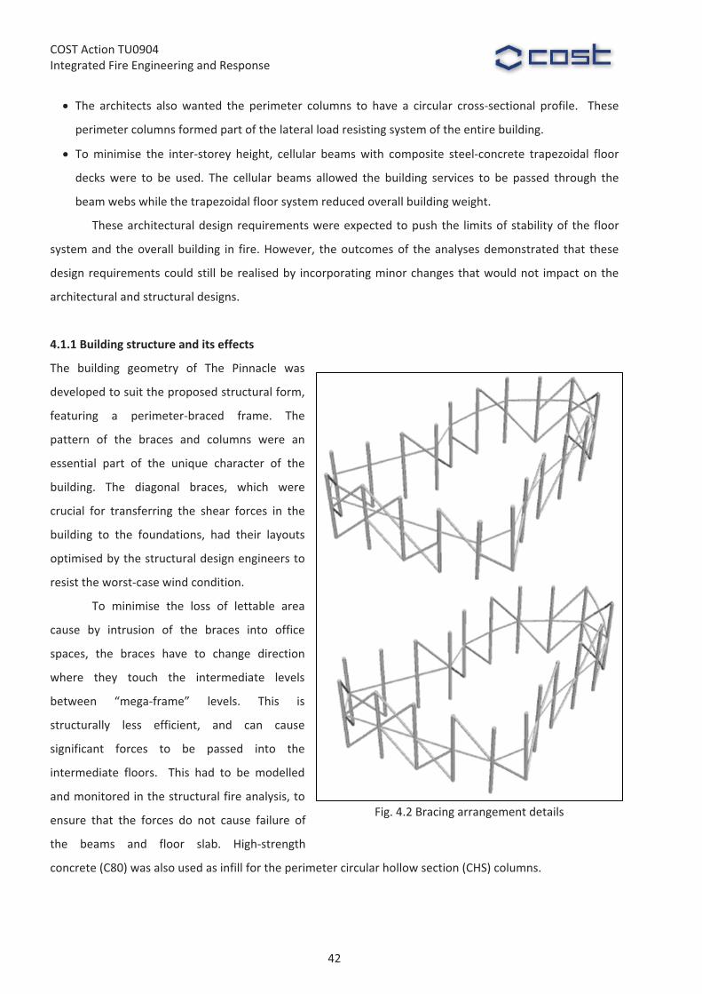
4.1.1�Building�structure�and�its�effects�
The� building� geometry� of� The� Pinnacle� was�
developed�to�suit�the�proposed�structural�form,�
featuring� a� perimeter�braced� frame.� The�
pattern� of� the� braces� and� columns� were� an�
essential� part� of� the� unique� character� of� the�
building.� The� diagonal� braces,� which� were�
crucial� for� transferring� the� shear� forces� in� the�
building� to� the� foundations,� had� their� layouts�
optimised�by�the�structural�design�engineers�to�
resist�the�worst�case�wind�condition.���
To� minimise� the� loss� of� lettable� area�
cause� by� intrusion� of� the� braces� into� office�
spaces,� the� braces� have� to� change� direction�
where� they� touch� the� intermediate� levels�
between� “mega�frame”� levels.� This� is�
structurally� less� efficient,� and� can� cause�
significant� forces� to� be� passed� into� the�
intermediate� floors.� � This� had� to� be� modelled�
and�monitored�in�the�structural�fire�analysis,�to�
ensure� that� the� forces� do� not� cause� failure� of�
the� beams� and� floor� slab.� High�strength�
concrete�(C80)�was�also�used�as�infill�for�the�perimeter�circular�hollow�section�(CHS)�columns.�
�
�
Fig.�4.2�Bracing�arrangement�details�
42
COST�Action�TU0904�Integrated�Fire�Engineering�and�Response�
4.2�FIRE�ENGINEERING�
4.2.1�Structural�fire�engineering�analysis�
There� were� many� unique� aspects� of� this� project� which� demonstrated� innovation� and� creativity.� � These�
included:�
• Very�large�complex�models�capturing�localised�and�global�behaviour�
• A�new�methodology�for�modelling�the�external�frame�over�multiple�floors�
• A�modelling�approach�for�a�composite�steel�and�concrete�column�system�in�fire�
• Modelling�techniques�to�allow�simulations�to�perform�efficiently�
• An�optimised�fire�protection�layout�tailored�to�the�structure�
Commonly� in� structural� fire� engineering,� small� and� simplified� representative� portions� of� a� floor�
within�a�building�with�a�regular�steel�frame�may�be�used�to�represent�its�overall�response�in�fire.�Usually,�a�
building� is� assumed� to� be� adequately� restrained� against� sway� by� the� lateral� stability� system,� which� is�
typically� a� reinforced� concrete� core,� and� assumed� to� be� unaffected� by� fire.� Because� the� lateral� stability�
system�of�The�Pinnacle�is�an�optimised�steel�bracing�system�located�around�the�entire�building�perimeter,�
the�entire�floor�plate�had�to�be�modelled.� �The�common�assumption�that�the� lateral�stability�system�was�
not�affected�by�fire�could�not�be�applied�for�this�building.��This�is�the�first�structural�fire�analysis�where�the�
lateral�forces�caused�by�wind,�and�the�entire�lateral�stability�system,�were�modelled�at�high�temperatures.��
The�global�behaviour�of�three�separate�extensive�full�floor�plates�comprising�irregular�cellular�beam�
arrangements� were� analysed.� A� novel� approach� taken� in� the� analysis� was� the� investigation� into� the�
behaviour� of� the� building’s� outer� lateral� load� supporting,� diagonal� grid� structure,� including�mega�frames�
spanning�three�storeys�and�incorporating�the�effects�of�wind�when�exposed�to�fire.�Detailed�models�of�part�
of� the� floor� plate� were� also� analysed� to� capture� complex� and� highly� localised� firerelated� structural�
phenomena�such�as�webpost�buckling�of� the�cellular�beams.� �The�models� that�were�developed�were�not�
only�the�largest�created�for�analysing�structural�fire�performance�within�Arup,�but�they�incorporated�a�very�
high� level� of� detail� and� complexity� to� allow� for� an� accurate� dynamic� representation� of� the� structural�
response�at�high�temperature.�Without�the�use�of�such�advanced�methods,� the�proposed�solution�would�
simply�not�be�possible�given�the�sheer�complexity�of�the�structural�arrangement.�
43

COST�Action�TU0904�Integrated�Fire�Engineering�and�Response�
�
�The�analysis�is�the�first�of�its�kind�to�assess�a�multi�storey�braced�external�tubular�system�(diagrid)�
that�spans�over�6�levels�with�mega�frame�floors�at�every�3�levels.�Wind�effects�and�redistribution�of�forces�
that� are� transferred� through� this� irregular� system� by� membrane� forces� within� the� slab� have� been�
quantified.� � It� is� the� first� analysis� in� structural� fire� engineering�which� quantifies� the� heating� and� cooling�
phase�over�an�entire�3,000m2�floor�plate�and�its�effects�on�connections�and�structural�elements�including�
the�diagrid.�The�analysis�incorporated�beam�and�column�connection�capacities�and�partial�shear�composite�
action�between�the�slab�and�beams.�
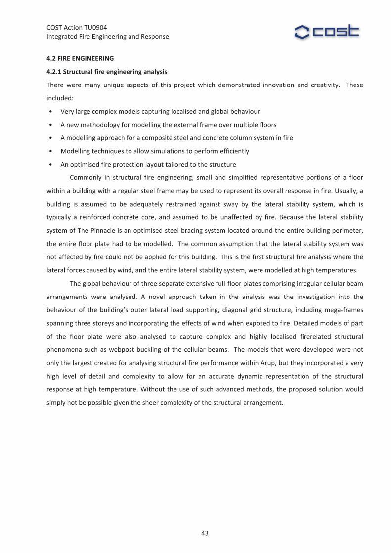
Fig.�4.3�ABAQUS�models�observing�localised�behaviour�of�composite�floor�employing�cellular�steel�downstand�beams�
44
COST�Action�TU0904�Integrated�Fire�Engineering�and�Response�
�
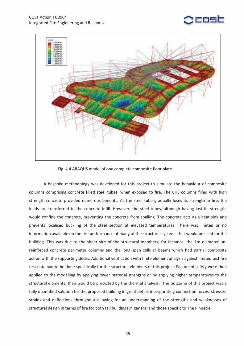
�A� bespoke�methodology�was� developed� for� this� project� to� simulate� the� behaviour� of� composite�
columns� comprising� concrete� filled� steel� tubes,�when� exposed� to� fire.� The� CHS� columns� filled�with� high�
strength� concrete� provided� numerous� benefits.� As� the� steel� tube� gradually� loses� its� strength� in� fire,� the�
loads� are� transferred� to� the� concrete� infill.� However,� the� steel� tubes,� although� having� lost� its� strength,�
would�confine� the�concrete,�preventing� the�concrete� from�spalling.�The� concrete�acts�as�a�heat� sink�and�
prevents� localised� buckling� of� the� steel� section� at� elevated� temperatures.� There� was� limited� or� no�
information�available�on�the�fire�performance�of�many�of�the�structural�systems�that�would�be�used�for�the�
building.� This� was� due� to� the� sheer� size� of� the� structural� members;� for� instance,� the� 1m� diameter� un�
reinforced� concrete� perimeter� columns� and� the� long� span� cellular� beams� which� had� partial� composite�
action�with�the�supporting�decks.�Additional�verification�with�finite�element�analysis�against�limited�test�fire�
test�data�had�to�be�done�specifically�for�the�structural�elements�of�this�project.�Factors�of�safety�were�then�
applied� to� the�modelling�by�applying� lower�material�strengths�or�by�applying�higher� temperatures� to� the�
structural�elements,�than�would�be�predicted�by�the�thermal�analysis.� �The�outcome�of�this�project�was�a�
fully�quantified�solution�for�the�proposed�building�in�great�detail,�incorporating�connection�forces,�stresses,�
strains� and� deflections� throughout� allowing� for� an� understanding� of� the� strengths� and� weaknesses� of�
structural�design�in�terms�of�fire�for�both�tall�buildings�in�general�and�those�specific�to�The�Pinnacle.�
Fig.�4.4�ABAQUS�model�of�one�complete�composite�floor�plate�
45

COST�Action�TU0904�Integrated�Fire�Engineering�and�Response�
4.2.3�Value�and�benefits�to�design�
The� analysis� resulted� in� an� optimised� fire� protection� arrangement,�
which�is�tailored�to�this�complex�structure,�increasing�its�robustness�and�
minimising� fire� protection�material.� � The� client� benefited� from� a� vast�
financial�saving�due�to�the�reduction�of�fire�protection�material�that�was�
specified� by� Arup� in� comparison� to� what� would� have� been� required�
under� prescriptive� Building� Regulations� (2000)� and� their� amplification�
documents� (ADB�2006,� LDSA�1997).� � The� client� also� received�a� robust�
and�quantified� solution� for� their� structure� that� allows� them� to� inform�
and�sell�on�the�value�of�the�building�with�respect�to�its�safety�in�future�
events.� The� occupiers� of� the� building�were� provided�with� a� structure�
designed� to� withstand� specific� extreme� events,� rather� than� unknown�
safety� levels� when� designed� to� prescriptive� code� requirements.� This�
project�demonstrated�significant�value�in�undertaking�detailed�analyses�
to� assess� the� structural� fire� robustness� of� unconventional� and� iconic�
buildings.�It�showed�that�a�structure�can�be�designed�to�perform�well�in�
fires�when�close�design�coordination�is�provided�between�the�structural�
engineers�and�fire�engineers.��
The� local� community� benefited� from� reduced� damage� to� the�
environment� through� reduced� use� of� noxious� materials� that� can� be�
common� in� fire� protection.� The� type� of� fire� protection� for� the� steel�
members� recommended� by� Arup� Fire� would� be� applied� offsite.� This�
would� increase� the� efficiency� of� assembly� of� steel� work� on� site� and�
minimise�the�application�on�site�which�would�pose�significant�occupational�health�and�safety�issues,�such�as�
working�at�height�and�overspray�of�fire�protection.� �By�optimising�the�amount�of� intumescent�paint�to�be�
applied� to� the� steelwork,� this� project� has� reduced� the� environmental� impact� as� the� structure� becomes�
more� environmentally� efficient� with� regard� to� the� volume� of� fire� protection,� had� the� fire� rating� been�
defined�according�to�Building�Regulations.�The�optimised�fire�protection�allows�the�intumescent�paint�to�be�
applied� in� a� single� coat� rather� than�multiple� coats� of� paint�which� needs� additional� curing� time,� creating�
wasted�energy�while�the�steel�beams�are�cured�in�the�workshop.�
�
�
Fig.�4.5�Full�structure�frame�model�
46
COST�Action�TU0904�Integrated�Fire�Engineering�and�Response�
4.3�OTHER�INFORMATION�
The�original�question�was�to�determine�a�cost�saving�with�respect�to�the�quantity�of�fire�protection�material�
required�for�the�structure,�as�compared�to�prescriptive�manufacturers’�guidance�(ASFP�2010).�This�became�
a�complex�study�on�unique�structural� forms�at�elevated�temperatures,�which�required�close�coordination�
with� the�Corporation�of� London�District� Surveyors�office,� their� third�party� checker�Prof.�Colin�Bailey,� the�
structural�engineers,�and�the�software�providers�ABAQUS:�to�create�sets�of�modelling�assumptions,�and�to�
apply� advanced� understanding� to� the� complex� behaviours� observed� as� a� result� of� fire.� Through� earlier�
research,�close�development�work�with�the�University�of�Edinburgh�and�a�proven�history�of�modelling�tall,�
iconic�structures�in�fire�had�allowed�us�to�provide�a�service�on�this�project�that�gave�confidence�to�the�client�
and�approving�authorities�that�a�safe�and�cost�effective�solution�could�be�achieved.�
Arup�Fire’s�strong�connection�with�universities�and�leading�role�in�developing�cutting�edge�research�
in�the�field�of�structural�fire�engineering�was�a�big�advantage�in�helping�to�overcome�some�of�the�unique�
challenges�that�the�project�faced.�A�closely�knit�working�team�of�specialised�structural�fire�engineers�with�a�
vast�experience�of�numerical�modelling�techniques�for�this�type�of�project�was�a�feature�that�is�unique�to�
Arup.�These�factors�result�in�a�capacity�to�provide�and�complete�such�a�challenging�task.�It�is�this�capability�
which�no�other�competitor�can�provide.�
�
References�ADB�(2006),�“Approved�Document�B���Fire�Safety,�2006�Edition”.�The�Stationery�Office�Ltd,�London,�UK.�ASFP�(2010),�“Fire�Protection�for�Structural�Steel�in�Buildings�(The�Yellow�Book)”,�4th�Edition,�Association�for�
Specialist�Fire�Protection,�2010.��Building�Regulations�(2000),�“The�Building�Regulations�for�England�and�Wales”,�The�Stationery�Office�Ltd,�
London,�UK.�LDSA�(1997),�“Fire�Safety�Guide�No�1���Section�20�Buildings”,�The�London�District�Surveyors’�Association.��
47
COST�Action�TU0904�Integrated�Fire�Engineering�and�Response�
WG2���Stephen�Hicks,�[email protected]��
Martin�Feeney,�[email protected]��
G.�Charles�Clifton,�[email protected]�� �
�
5�FIRE�PERFORMANCE�OF�AN�OFFICE�BUILDING�WITH�LONG�SPAN�CELLULAR�
FLOOR�BEAMS���BRITOMART�EAST,�AUCKLAND��
�
�
Summary�
This� case� study� describes� the� application� of� a� structural� fire� model� to� a� 12�storey� office� building� in�
Auckland,� which� was� one� of� the� first� New� Zealand� projects� to� use� long�span� cellular� floor� beams.� The�
structural�fire�model�employed�is�known�as�the�Slab�Panel�Method�(SPM)�and�was�developed�by�the�Heavy�
Engineering� Research� Association� (HERA).� The� SPM� predictions� of� peak� deflection� under� fire� were�
investigated�by�more�accurate�Abaqus/Explicit�simulations�for�a�range�of�design�fire�severities�and�indicated�
that,� for� this� form� of� construction,� there� is� a� tendency� for� the� bottom� flange� of� the� cellular� beams� to�
displace�laterally�(which�has�recently�been�verified�experimentally�in�the�RFCS�FiCEB+�project).��From�these�
analyses� it� was� demonstrated� that� the� passive� fire� protection� could� be� eliminated� from� the� long�span�
secondary�beams,�with�only�elements�critical�to�the�structural�stability�of�the�floor�requiring�the�application�
of� fire� proofing� materials.� The� resulting� 80%� reduction� to� the� passive� fire� protection� on� the� long�span�
cellular�beams�led�to�significant�cost�savings�to�the�Client.�
�
5.1�INTRODUCTION�
The� fire� resistance� of� steel� structures� in� office� buildings,� and� their� inelastic� reserve� of� strength� in� fully�
developed� fires,� has� received� significant� attention� internationally.� Through� New� Zealand’s� performance�
based� Building� Code,� there� has� been� a� strong� focus� on� designing� for� the� expected� performance� in� fire�
rather�than�simply�adopting�traditional�prescriptive�requirements,�which�typically�involve�the�application�of�
passive� fire� protection� to� all� structural� steel� members;� this� is� especially� the� case� in� sprinkler� protected�
buildings,� given� the� very� high� effectiveness� of� sprinklers� in� preventing� fire� growth� reaching� full�
development� (see� Feeney� and�Buchanan).� As� a� consequence�of� this,� in� sprinkler� protected�buildings� the�
inelastic� response� in� fully� developed� fires� is� an� acceptable� ultimate� limit� state� response� provided� that�
collapse�does�not�occur�and�the�floors�continue�to�function�as�effective�fire�separations.��
One�of�the�principal�design�procedures�developed�in�New�Zealand�to�take�account�of�this�inelastic�
reserve� of� strength� is� the� Slab� Panel�Method� (SPM).� The� SPM� is� the� culmination� of� 8�years� of� research�
undertaken�by�HERA�and�the�University�of�Canterbury,�which�extended�Bailey’s� tensile�membrane�model�
48
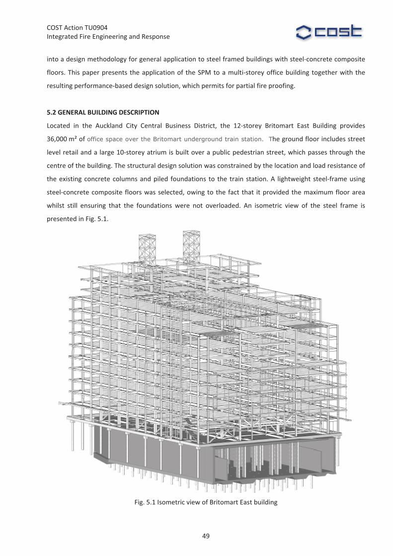
COST�Action�TU0904�Integrated�Fire�Engineering�and�Response�
into�a�design�methodology�for�general�application�to�steel�framed�buildings�with�steel�concrete�composite�
floors.�This�paper�presents� the�application�of� the�SPM�to�a�multi�storey�office�building� together�with� the�
resulting�performance�based�design�solution,�which�permits�for�partial�fire�proofing.�
�
5.2�GENERAL�BUILDING�DESCRIPTION�
Located� in� the� Auckland� City� Central� Business� District,� the� 12�storey� Britomart� East� Building� provides�
36,000�m²�of�office space over the Britomart underground train station. The�ground�floor�includes�street�
level�retail�and�a�large�10�storey�atrium�is�built�over�a�public�pedestrian�street,�which�passes�through�the�
centre�of�the�building.�The�structural�design�solution�was�constrained�by�the�location�and�load�resistance�of�
the�existing� concrete� columns�and�piled� foundations� to� the� train� station.�A� lightweight� steel�frame�using�
steel�concrete�composite� floors�was�selected,�owing�to� the� fact� that� it�provided�the�maximum�floor�area�
whilst� still� ensuring� that� the� foundations� were� not� overloaded.� An� isometric� view� of� the� steel� frame� is�
presented�in�Fig.�5.1.�
�Fig.�5.1�Isometric�view�of�Britomart�East�building�
49

COST�Action�TU0904�Integrated�Fire�Engineering�and�Response�
Due� to� geometric� constraints� imposed� by� the� foundations� to� the� existing� train� station,� the�
structural�grid�for�the�building�was�not�ideal�for�a�steel�frame�solution;�moreover,�the�New�Zealand�seismic�
design�requirements�had�a�strong�influence�on�the�size�of�the�structural�members.�As�a�result�of�these�two�
influences,�many�of�the�structural�steel�elements�within�this�project�were�sized�for�stiffness�which�resulted�
in�a�reserve�in�resistance�under�gravity�loads�at�room�temperature,�thereby�improving�the�performance�in�
fire�conditions.�During�the�design�development,�two�steel�solutions�were�considered�viz.:�composite�beams�
using� conventional� UB� sections,� and� long�span� cellular� beams.� The� final� solution� that� was� selected� was�
cellular� beams,� owing� to� the� fact� that� they� provide� much� greater� flexibility� for� installation� of� building�
services,�together�with�a�lower�steel�weight�per�square�metre.�
The� floor� consists� of� a� 130� mm� deep� concrete� slab� cast� on� ComFlor� 60� profiled� steel� sheeting�
spanning� 2.75�m�between� secondary� beams.� The� secondary� beams� consisted�of� 496×171/190×56.1�kg/m��
Asymmetric�Cellular�Beam�(ACB)�sections�with�300�mm�diameter�cells�at�535�mm�cross�centres.�The�ACB’s�
spanned� 12.0�m�which,� in� turn,�were� supported� by� primary� beams� utilising� 800×122�kg/m� and� 800×146�
kg/m�Welded�Beam�(WB)�sections�spanning�11.0�m�between�columns.�Due�to�a�span�to�depth�ratio�of�24,�
together�with�the�fact�that�unpropped�construction�was�used,�the�ACB’s�were�supplied�with�a�40�mm�pre�
camber� in� order� to� satisfy� total� deflection� requirements.� A� general� arrangement� of� a� typical� floor� is�
presented� in� Fig.� 5.2.� The� lateral� load� resisting� system� consists� of� steel� moment� resisting� frames.� The�
external�perimeter�cladding�is�a�mix�of�curtain�wall�glazing�and�concrete�cladding�panels.��
With� the� exception� of� the� roof� level� to� the� 10�storey� atrium,� the� building� is� protected� with� an�
automatic�sprinkler�system�in�all�areas.�Passive�fire�separation�is�also�provided�between�all�floors�with�a�60�
minutes� fire� resistance� rating,� as� well� as� automatic� smoke� detection� and� a� voice�messaging� system� for�
staged�evacuation�of�different�parts�of�the�building.�
�
5.3�REGULARATORY�REQUIREMENTS�
The�mandatory�provisions�for�building�work�are�contained�within�the�New�Zealand�Building�Code�(NZBC),�
which� consists� of� the� First� Schedule� to� the� Building� Regulations� 1992.� The� NZBC� is� performance�based,�
which� means� that� a� designer� has� the� freedom� to� use� any� method� to� comply,� provided� that� they� can�
demonstrate�to�the�local�building�consent�authority�that�the�performance�specified�in�the�relevant�Building�
Code�clauses�will�be�met.�Structural�stability�during�fire�is�a�requirement�of�NZBC�Clauses�B1�Structure�and�
Clause�C4�Structural�Stability�During�Fire.��
The�performance�requirement�in�NZBC�Clause�B1�is�that�“Buildings�…�shall�have�a�low�probability�of�
becoming�unstable,�losing�equilibrium,�or�collapsing�...�throughout�their�lives�...�Account�shall�be�taken�of�all�
physical�conditions� likely�to�affect�the�stability�of�buildings�...� including�self�weight,� imposed�gravity� loads�
arising� from� use,� …� fire,� ...”.� The� functional� requirement� in� NZBC� Clause� C4� is� to� “maintain� structural�
stability�during�fire�to:�(a)�Allow�people�adequate�time�to�evacuate�safely;�(b)�Allow�fire�service�personnel�
50
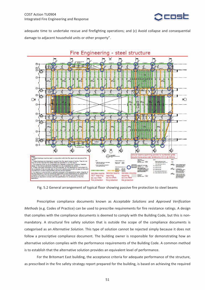
COST�Action�TU0904�Integrated�Fire�Engineering�and�Response�
adequate� time�to�undertake�rescue�and� firefighting�operations;�and� (c)�Avoid�collapse�and�consequential�
damage�to�adjacent�household�units�or�other�property”.�
�
�Fig.�5.2�General�arrangement�of�typical�floor�showing�passive�fire�protection�to�steel�beams�
�
Prescriptive� compliance� documents� known� as� Acceptable� Solutions� and� Approved� Verification�
Methods�(e.g.�Codes�of�Practice)�can�be�used�to�prescribe�requirements�for�fire�resistance�ratings.�A�design�
that�complies�with�the�compliance�documents�is�deemed�to�comply�with�the�Building�Code,�but�this�is�non�
mandatory.� A� structural� fire� safety� solution� that� is� outside� the� scope� of� the� compliance� documents� is�
categorised�as�an�Alternative�Solution.�This�type�of�solution�cannot�be�rejected�simply�because�it�does�not�
follow�a�prescriptive�compliance�document.�The�building�owner� is� responsible� for�demonstrating�how�an�
alternative�solution�complies�with�the�performance�requirements�of�the�Building�Code.�A�common�method�
is�to�establish�that�the�alternative�solution�provides�an�equivalent�level�of�performance.��
For�the�Britomart�East�building,�the�acceptance�criteria�for�adequate�performance�of�the�structure,�
as�prescribed�in�the�fire�safety�strategy�report�prepared�for�the�building,�is�based�on�achieving�the�required�
51
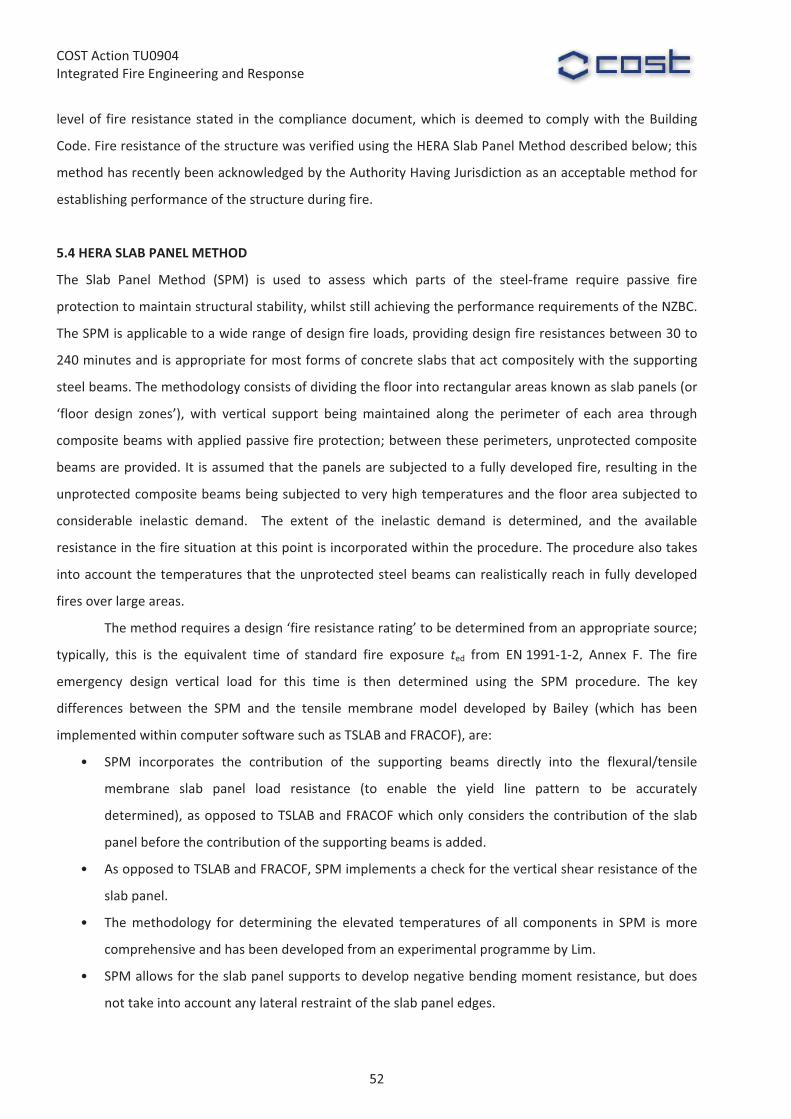
COST�Action�TU0904�Integrated�Fire�Engineering�and�Response�
level�of� fire� resistance�stated� in� the�compliance�document,�which� is�deemed�to�comply�with� the�Building�
Code.�Fire�resistance�of�the�structure�was�verified�using�the�HERA�Slab�Panel�Method�described�below;�this�
method�has�recently�been�acknowledged�by�the�Authority�Having�Jurisdiction�as�an�acceptable�method�for�
establishing�performance�of�the�structure�during�fire.�
�
5.4�HERA�SLAB�PANEL�METHOD��
The� Slab� Panel� Method� (SPM)� is� used� to� assess� which� parts� of� the� steel�frame� require� passive� fire�
protection�to�maintain�structural�stability,�whilst�still�achieving�the�performance�requirements�of�the�NZBC.�
The�SPM�is�applicable�to�a�wide�range�of�design�fire�loads,�providing�design�fire�resistances�between�30�to�
240�minutes�and�is�appropriate�for�most�forms�of�concrete�slabs�that�act�compositely�with�the�supporting�
steel�beams.�The�methodology�consists�of�dividing�the�floor�into�rectangular�areas�known�as�slab�panels�(or�
‘floor� design� zones’),� with� vertical� support� being� maintained� along� the� perimeter� of� each� area� through�
composite�beams�with�applied�passive�fire�protection;�between�these�perimeters,�unprotected�composite�
beams�are�provided.�It� is�assumed�that�the�panels�are�subjected�to�a�fully�developed�fire,�resulting�in�the�
unprotected�composite�beams�being�subjected�to�very�high�temperatures�and�the�floor�area�subjected�to�
considerable� inelastic� demand.� � The� extent� of� the� inelastic� demand� is� determined,� and� the� available�
resistance�in�the�fire�situation�at�this�point�is�incorporated�within�the�procedure.�The�procedure�also�takes�
into�account�the�temperatures�that�the�unprotected�steel�beams�can�realistically�reach�in�fully�developed�
fires�over�large�areas.��
The�method�requires�a�design�‘fire�resistance�rating’�to�be�determined�from�an�appropriate�source;�
typically,� this� is� the� equivalent� time� of� standard� fire� exposure� ted� from� EN�1991�1�2,� Annex� F.� The� fire�
emergency� design� vertical� load� for� this� time� is� then� determined� using� the� SPM� procedure.� The� key�
differences� between� the� SPM� and� the� tensile� membrane� model� developed� by� Bailey� (which� has� been�
implemented�within�computer�software�such�as�TSLAB�and�FRACOF),�are:�
• SPM� incorporates� the� contribution� of� the� supporting� beams� directly� into� the� flexural/tensile�
membrane� slab� panel� load� resistance� (to� enable� the� yield� line� pattern� to� be� accurately�
determined),�as�opposed�to�TSLAB�and�FRACOF�which�only�considers�the�contribution�of� the�slab�
panel�before�the�contribution�of�the�supporting�beams�is�added.��
• As�opposed�to�TSLAB�and�FRACOF,�SPM�implements�a�check�for�the�vertical�shear�resistance�of�the�
slab�panel.�
• The�methodology� for� determining� the� elevated� temperatures� of� all� components� in� SPM� is�more�
comprehensive�and�has�been�developed�from�an�experimental�programme�by�Lim.�
• SPM�allows�for�the�slab�panel�supports�to�develop�negative�bending�moment�resistance,�but�does�
not�take�into�account�any�lateral�restraint�of�the�slab�panel�edges.�
52

COST�Action�TU0904�Integrated�Fire�Engineering�and�Response�
• The� limits� on�maximum�deflection� of� the� slab� panel� initially� recommended� by� Bailey� have� been�
modified� through� experimental� testing� and� analytical� modelling� undertaken� in� the� NZ� research�
programme.��
• The�SPM�provides�comprehensive�structural�detailing�requirements�to�ensure�that�the�floor�panel�
can�dependably�develop�the�design�deformations�without�loss�of�structural�stability�or�integrity�
As�a�further�verification�of�the�methodology,�work�conducted�by�the�third�author�has�also�shown�that�the�
results�from�SPM�agree�favourably�with�those�from�the�finite�element�program�Vulcan.�
�
5.5�CONSIDERED�DESIGN�FIRE�SCENARIOS�
Regardless�of�the�very�low�probability�that�a�fire�in�the�sprinklered�Britomart�building�would�reach�flashover�
conditions� and� adversely� affect� the� structure� (annual� probability� of� less� than� 1.2×10�5),� the� fire� scenario�
selected� to� represent� the� design� case� is� the� low� probability� event� of� a� fire� not� being� controlled� by� the�
sprinkler�system,�which�reaches�full�development.�This�assumes�that�the�sprinklers�do�not�operate�and�that�
a�fire�grows�uncontrolled�by�any�manual�or�automatic�intervention.��
A�range�of�structural�fire�severities�were�determined�and�the�SPM�was�applied�to�the�most�severe�
of� these.� The� average� structural� fire� severity� (equivalent� length� of� time� of� ISO� 834� exposure)� was� 45�
minutes,�the�maximum�was�75�minutes�and�an�80%�value�was�just�under�60�minutes.�As�well�as�evaluating�
the� response� of� the� structure� to� a� range� of� fire� conditions,� the� post�fire� cooling� down� period� was� also�
considered.�For�45�minutes�structural�fire�severity,�the�cooling�down�period�was�considerably�longer�at�255�
minutes.�
�
5.6�FINITE�ELEMENT�ANALYSES�
The�Britomart�floor�system�consists�of�composite�slabs�supported�by�a�network�of�primary�and�secondary�
steel�beams�(see�Fig.�5.3).�Under�ambient�temperature�conditions,�the�floor�is�designed�to�act�as�a�series�of�
one�way� load� spanning� elements.� As� specified� in� the� SPM�procedure,� under� severe� fire� the�unprotected�
secondary�beams�lose�their�strength�and�the�floor�system�responds�as�a�two�way�‘slab�panel’�element.�Each�
slab�panel�has�4� sides,�with�each� side� required� to�have� sufficient� strength� to� support� the� tributary� loads�
direct�from�the�slab�panel.�This�means�that�for�the�sides�of�the�panel�supported�on�secondary�beams,�the�
supporting� beams�may� need� to� resist� a� larger� vertical� load� in� the� fire� emergency� condition� than� those�
present� in� ambient� temperature� conditions,� even� though� the� load� per� square� metre� is� lower;� this� is�
because� of� the� higher� tributary� area� on� these� secondary� support� beams.� For� conventional� solid� web�
secondary� beams,� there� is� normally� sufficient� resistance� as� the� beam� size� is� governed� by� deflection� or�
vibration�considerations.�
53
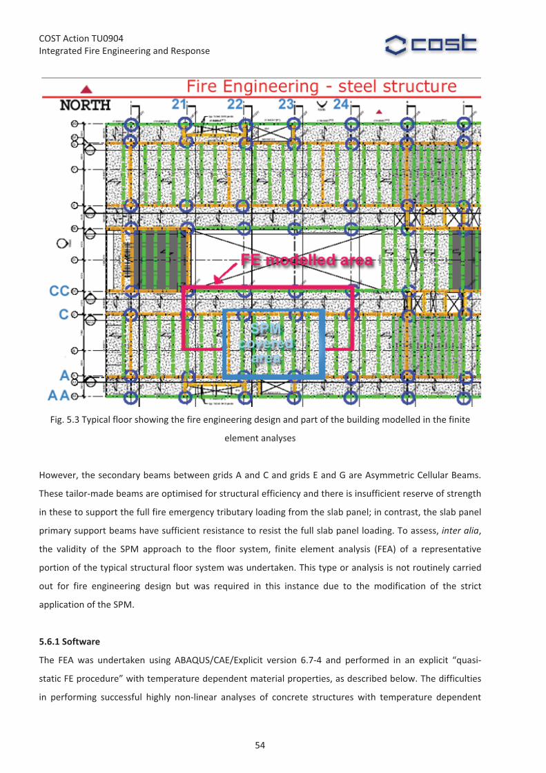
COST�Action�TU0904�Integrated�Fire�Engineering�and�Response�
�Fig.�5.3�Typical�floor�showing�the�fire�engineering�design�and�part�of�the�building�modelled�in�the�finite�
element�analyses�
�
However,�the�secondary�beams�between�grids�A�and�C�and�grids�E�and�G�are�Asymmetric�Cellular�Beams.�
These�tailor�made�beams�are�optimised�for�structural�efficiency�and�there�is�insufficient�reserve�of�strength�
in�these�to�support�the�full�fire�emergency�tributary�loading�from�the�slab�panel;�in�contrast,�the�slab�panel�
primary�support�beams�have�sufficient�resistance�to�resist�the�full�slab�panel�loading.�To�assess,�inter�alia,�
the� validity� of� the� SPM� approach� to� the� floor� system,� finite� element� analysis� (FEA)� of� a� representative�
portion�of�the�typical�structural�floor�system�was�undertaken.�This�type�or�analysis�is�not�routinely�carried�
out� for� fire� engineering� design� but� was� required� in� this� instance� due� to� the� modification� of� the� strict�
application�of�the�SPM.�
�
5.6.1�Software�
The� FEA� was� undertaken� using� ABAQUS/CAE/Explicit� version� 6.7�4� and� performed� in� an� explicit� “quasi�
static�FE�procedure”�with�temperature�dependent�material�properties,�as�described�below.�The�difficulties�
in� performing� successful� highly� non�linear� analyses� of� concrete� structures� with� temperature� dependent�
54

COST�Action�TU0904�Integrated�Fire�Engineering�and�Response�
material� properties� are� well� known.� Implicit� codes� (such� as� SAFFIR,� ABAQUS/Standard)� do� not� always�
provide�a� convergent� solution�and�FE� simulations� like� those�presented�are�almost� impossible� to�perform�
with� them.� The� Britomart� finite� element�model� size,� complexity� and� the� need� for� an� extended� duration�
deflection� history� dictated� the� explicit� approach.� This� allowed� the�models� to� progress� beyond� failure� in�
some�of�their�regions,�so�large�deflections�could�be�captured�in�many�simulations.�
The�first�aim�of�the�FEA�was�to�determine�the�adequacy�of�the�modified�application�of�the�SPM�as�
part� of� the� design� solution.� The� second� aim,� which�was� equally� important,� was� to� determine� the� likely�
response�of�the�structure�to�the�range�of�fire�conditions�expected�and�at�the�end�of�the�post�fire�cooling�
down�phase.�For�the�first�case�considered,�which�was�based�on�applying�the�prescriptive�solution�given�in�
the� Approved� Document� for� Fire� Safety� (C/AS1),� the� analysis� required� simulation� of� the� structural�
behaviour� for� approximately� 45�minutes�heating�up�and� for� the�much� longer�255�minutes� cooling�down�
period.� The� simulation� of� this� long� lasting� fire� condition� is� challenging� in� explicit� codes,� therefore� “time�
scaling”�and�mass�scaling�were�used�to�obtain�the�solution�within�a�reasonable�time�frame�(up�to�one�day).�
A�more�detailed�description�of�this�analysis�is�given�by�Mago�et�al.��
�
5.6.2�Material�Properties�
Both�primary�and�secondary�beams�used�grade�300�steel�supplied�according�to�AS/NZS�3679.�The�concrete�
had� a� characteristic� compressive� cylinder� strength� of� 30� MPa.� The� temperature� dependent� material�
properties�using�EN�1994�1�2�were�taken�into�account�within�the�finite�element�models.�
�
5.6.3�Slab�modelling�
The� composite� slabs� used� in� the� building� consist� of� a� 130�mm� deep� concrete� slab� cast� on� ComFlor� 60�
profiled�steel�sheeting.�Full�shear�connection�between�the�beams�and�the�composite�slabs�was�assumed.�
An�equivalent�reinforced�concrete�slab�of�100mm�thickness�was�used�to�represent�the�composite�slab.�This�
approximation�has�been�previously�shown�to�be�valid�in�the�modeling�of�experimental�testing�undertaken�
as� part� of� the� SPM�development,� provided� that� the� reinforcement� position� and� area� is� adjusted� to� give�
equivalent�load�carrying�capacity.��
�
5.6.4�Connections�
All�beams�in�moment�frames�were�fully�welded�to�the�columns,�while�the�webs�to�the�cellular�beams�were�
bolted�to�the�web�of�the�primary�beam�or�column�with�a�web�cleat.�
�
5.6.5�Boundary�Conditions�
Columns�were�represented�as�extending�to�floor�levels�below�and�above�the�compartment�in�the�FE�model.�
At� the� lower� level� the�columns�were� fixed�or�pinned�as�appropriate,�whilst�at� the�upper� level� they�were�
55
COST�Action�TU0904�Integrated�Fire�Engineering�and�Response�
axially� loaded�with�design�forces�from�the�levels�above.�The�boundary�conditions�allowed�the�columns�to�
extend�only�upwards.�
Fig.�5.3�shows�part�of�the�building�on�which�FEA�was�undertaken.��Lateral�support�conditions�were�
varied� from� free� to� restrained� (symmetrical� boundary� conditions)� along� grid� lines�21�and�24,� since� finite�
element� sub�modelling� was� not� applicable� in� this� case.� In� practice,� all� the� slab� panels� are� laterally�
restrained� to� some� extent� (which� was� incorporated� into� the� FEA),� whilst� the� SPM� assumes� no� lateral�
restraint�to�any�panel�in�the�plane�of�the�slab.�Symmetry�was�assumed�in�the�midpoint�between�grid�lines�A�
and�C�(see�Fig.5.3).�
�
5.6.6�Loading�
At�ambient�temperature,�the�design�imposed�load�in�the�office�areas�was�3.5�kPa.�In�checking�the�strength�
and� stability� of� the� structure� at� the� fire� limit� state,� the� loads� should� be�multiplied� by� the� relevant� load�
factors,�which�resulted�in�a�fire�emergency�load�of�1.9�kPa.�The�superimposed�dead�load�on�the�floor�was�
0.5� kPa.� In� the� first� step� of� the� analysis,� the� uniformly� distributed� loads� (including� the� self�weight,�
superimposed�dead�load�and�fire�emergency�load)�and�column�forces�were�applied�in�a�smooth�quasi�static�
explicit�procedure.�This�step�was�followed�by�the�fire�loading�step.�
�
5.7�RESULTS�FROM�FINITE�ELEMENT�ANALYSES�
Two�cases�were�analysed�in�the�investigation.�The�first�case�was�based�on�applying�the�prescriptive�solution�
given�in�the�Approved�Document�for�Fire�Safety�(C/AS1)�involving�application�of�passive�fire�protection�to�
all�steel�members�to�achieve�a�fire�resistance�rating�of�45�minutes.�This�was�analysed�for�the�natural� fire�
condition�conditions�followed�by�a�cooling�down�period�so�that�the�results�of�the�SPM�design�solution�and�
the�Acceptable�Solution�could�be�compared.�The�deformed�shape�for�the�natural�fire�condition�is�shown�in�
Fig.�5.4,�which�considers� the�area�bounded�by�grid�lines�CC/21�24�extending�to�the�midpoint�of� the�floor�
between�grid�lines�A�and�C.��
The� second� case� (which� was� implemented� in� the� final� design),� is� a�more� cost� effective� solution�
based�on�selective�fire�protection�of�the�cellular�beams�comprising�slab�panel�supports�in�the�North�South�
direction,�whilst�leaving�unprotected�the�cellular�beams�within�the�slab�panel�region.�The�edge�beams�were�
also�left�unprotected.�Whilst�the�slab�panel�between�grid�lines�C�and�CC�(also�A�and�AA�and�the�other�side�
of�the�building)�is�satisfactory,�it�was�found�that�the�strain�demands�and�deflections�of�the�primary�beams�
on�grid�line�CC�were�too�high�if�these�were�left�unprotected�and�laterally�unstiffened.��
From�a�preliminary�FEA,�it�was�found�that�twisting�of�the�secondary�beams�in�the�positive�moment�
region�occurred�during�the�heating�stage,�which� led�to�significant� lateral� instability�and�movement�of�the�
bottom�flange�to�the�asymmetric�cellular�beams�(this�has�recently�been�observed�in�the�full�scale�fire�test�
conducted� at� the� University� of� Ulster� in� the� RFCS� FiCEB+� project).� To� remedy� this� situation,� as� well� as�
56
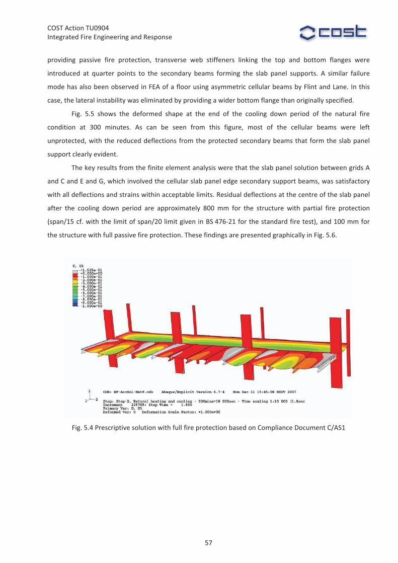
COST�Action�TU0904�Integrated�Fire�Engineering�and�Response�
providing� passive� fire� protection,� transverse� web� stiffeners� linking� the� top� and� bottom� flanges� were�
introduced� at� quarter� points� to� the� secondary� beams� forming� the� slab� panel� supports.� A� similar� failure�
mode�has�also�been�observed�in�FEA�of�a�floor�using�asymmetric�cellular�beams�by�Flint�and�Lane.�In�this�
case,�the�lateral�instability�was�eliminated�by�providing�a�wider�bottom�flange�than�originally�specified.�
Fig.� 5.5� shows� the� deformed� shape� at� the� end� of� the� cooling� down� period� of� the� natural� fire�
condition� at� 300� minutes.� As� can� be� seen� from� this� figure,� most� of� the� cellular� beams� were� left�
unprotected,�with�the�reduced�deflections�from�the�protected�secondary�beams�that�form�the�slab�panel�
support�clearly�evident.�
The�key�results�from�the�finite�element�analysis�were�that�the�slab�panel�solution�between�grids�A�
and�C�and�E�and�G,�which�involved�the�cellular�slab�panel�edge�secondary�support�beams,�was�satisfactory�
with�all�deflections�and�strains�within�acceptable�limits.�Residual�deflections�at�the�centre�of�the�slab�panel�
after� the� cooling� down� period� are� approximately� 800�mm� for� the� structure� with� partial� fire� protection�
(span/15�cf.�with�the�limit�of�span/20�limit�given�in�BS�476�21�for�the�standard�fire�test),�and�100�mm�for�
the�structure�with�full�passive�fire�protection.�These�findings�are�presented�graphically�in�Fig.�5.6.�
�
�Fig.�5.4�Prescriptive�solution�with�full�fire�protection�based�on�Compliance�Document�C/AS1�
�
57

COST�Action�TU0904�Integrated�Fire�Engineering�and�Response�
�Fig.�5.5�Final�design�solution�based�on�SPM�analysis�with�partial�fire�protection�
� SLAB CENTRAL SAGGING (NODE N2) COMPARISON
-900
-800
-700
-600
-500
-400
-300
-200
-100
00 50 100 150 200 250 300
TIME (MINUTES)
SLA
B C
ENTR
AL
SAG
GIN
G -
NO
DE
N2
(mm
)
Design solution with restrained BC at grid lines 21 and 24 - CLAMPED COLUMNSDesign solution with free BC at grid lines 21 and 24 - CLAMPED COLUMNSDesign solution with free BC at grid lines 21 and 24 - PINNED COLUMNSAcceptable solution with restrained BC at grid lines 21 and 24 - CLAMPED COLUMNS
�Fig.�5.6�Vertical�deflection�time�history�at�the�centre�of�slab�panel�for:�partial�fire�protection�(Design�
solution);�and�full�fire�protection�(Acceptable�Solution)�based�on�based�on�Compliance�Document�C/AS1�
�
As�can�be�seen�from�Fig.�5.6,�the�deflections�and�strains�in�the�all�beams�for�the�full�fire�protected�
solution�are�much�lower�than�in�the�partial�fire�protection�design�solution.�However,�the�post�fire�residual�
deflections�would�still�be� too� large� to� reinstate� the� floor�without� requiring�significant� remedial�work�and�
either�in�situ�beam�re�straightening�or�replacement.�Although,�in�theory,�it�might�be�possible�to�re�level�the�
top�of� concrete�with� a� levelling� compound,� the� structure� is� unlikely� to�have� the� capacity� to� support� the�
additional�weight,�particularly�if�more�than�one�floor�needed�to�be�reinstated.�
58

COST�Action�TU0904�Integrated�Fire�Engineering�and�Response�
5.8�SUMMARY�OF�FINAL�DESIGN�
All� structural� columns� have� passive� fire� protection� (60�minute� fire� rating)� to� ensure� that� the� slab� panel�
gravity�loads�are�supported.�The�beams�in�the�main�lateral�load�resisting�frames�(grid�lines�A1,�C,�E�and�G)�
are�all� fire�protected.� Selected�beams�on� the�perimeter� (grid� lines�AA,�CC,�EE�and�GG)�are�also�passively�
protected.�However,� approximately� 80%�of� the� secondary� beams� do�not� require� passive� fire� protection.�
This� reduced�extent�of� passive� fire�protection�has� resulted� in� a� saving�of�more� than�NZ$300,000� for� the�
project.�
For�the�two�cases�considered�in�the�FEA,�the�outcome�was�the�same�for�all�practical�purposes.�The�
large� deflections� and� corresponding� damage� to� the� structure� exposed� to� the� effects� of� a� severe�
uncontrolled� fire�would�require�replacement�of� the�affected�beams�and�floor�slab,� regardless�of�whether�
partial� of� full� passive� fire� protection� is� provided.� In� both� cases� structural� collapse� is� avoided,� the� load�
carrying�capacity�is�maintained�and�the�floors�would�be�expected�to�function�as�an�effective�fire�separation�
for�the�duration�of�the�fire.�
Passive�protection�of�all�beams�does�not�eliminate�the�need�for�detailed�assessment�and�probable�
repair�of�the�floor�after�being�subjected�to�fully�developed�fire.�A�much�more�effective�fire�safety�strategy�is�
to�rely�on�the�high�effectiveness�of�the�sprinkler�system�(Bennetts�et�al.),�to�suppress�full�fire�development�
and�to�mobilise�the�inelastic�reserve�of�strength�from�the�floor�in�the�very�remote�event�of�sprinkler�failure.�
That�is�the�approach�behind�the�SPM�method�and�the�approach�taken�in�this�design.�
�
5.9�REGULATORY�APPROVAL�
The� Building� Consent� Authority� responsible� for� regulatory� approval� (confirming� that� a� proposed� design�
complies� with� the� Building� Code),� is� Auckland� City� Environments.� Review� of� structural� design� required�
specialist�expertise�beyond�that�available�from�Auckland�City�staff,�so�reliance�was�placed�on�external�peer�
review.�The�structural�fire�design�for�the�Britomart�East�building�was�reviewed�independently�for�Building�
Code�compliance�on�behalf�of�the�Building�Consent�Authority.�
�
5.10�CONCLUSIONS�
This�paper�presents�the�application�of�the�Slab�Panel�Method�to�a�new�12�level�office�building�in�Auckland,�
New�Zealand.� From� this� case� study� it� can�be� seen� that� design�methods� are�maturing� to� a� level�where� a�
dependable� and� robust� performance� can� be� predicted� using� the� Slab� Panel� Method� (SPM).� The� SPM�
analysis�shows�that�if�sprinklers�fail�to�control�a�fire�such�that�flashover�is�prevented,�the�structure�retains�
sufficient� strength� to� support� design� loads� for� the� fire� load� condition.� Accordingly,� those� parts� of� the�
structure� which� require� applied� fire� protection� can� be� specified� with� enough� protection� to� maintain�
structural�stability,�and�those�parts�which�do�not�need�this�passive�fire�protection�can�be�safely�constructed�
59

COST�Action�TU0904�Integrated�Fire�Engineering�and�Response�
without�fire�protection.�The�extent�of�fire�proofing�that�is�not�required�to�satisfy�Building�Code�performance�
criteria�has�been�identified,�resulting�in�a�significant�cost�saving�to�the�project.��
Validation�of�the�dependable�structure�performance�with�the�reduced�level�of�fire�protection�was�
made�using�finite�element�analyses.�The�finite�element�analyses�also�show�that,�for�a�structure�protected�
with�passive�fire�protection�(as�required�to�comply�with�a�prescriptive�fire�safety�solution�and�exposed�to�
the�fire�severity�of�a�fully�developed�fire),�large�deformations�can�still�be�expected�thereby�requiring�post�
fire�replacement�of�affected�structure.�This�case�study�demonstrates�that�the�SPM�method�can�be�used�to�
assess�structure�performance�in�fire�in�a�performance�based�regulatory�environment.�
�
Acknowledgements��
The�authors�wish�to�acknowledge,�with�thanks,�the�building�owner,�Bluewater�Company,�and�the�structural�
engineer,�Holmes�Consulting�Group�Ltd,�for�their�cooperation�and�assistance�with�the�structural�fire�design�
for�this�project.�Thanks�also�go�to�Nandor�Mago,�who�was�responsible�for�the�finite�element�analyses.�
�
References�
Abu,� AK,� Burgess,� IW� and� Plank,� RJ.� "Analysis� of� Tensile�Membrane� Action� in� Composite� Slabs� in� Fire",�Proceedings� of� the� 2007� Pacific� Structural� Steel� Conference,� Wairakei,� New� Zealand,� 2007;� New�Zealand�HERA.�Manukau�City,�New�Zealand.�
AS/NZS� 3679.1:2010� Structural� steel� �� Hot�rolled� bars� and� sections,� Standards� Australia/Standards� New�Zealand,�Sydney/Wellington,�Australia/New�Zealand.�
AS/NZS� 3679.2:2010� Structural� steel� �� Welded� I� sections,� Standards� Australia/Standards� New� Zealand,�Sydney/Wellington,�Australia/New�Zealand.�
Bailey,� C.� G.� &�Moore,� D.� B.� (2000)� The� structural� behaviour� of� steel� frames�with� composite� floor� slabs�subject�to�fire,�Part�1:�Theory,�The�Structural�Engineer,�June.�
Bailey,� C.� G.� &�Moore,� D.� B.� (2000)� The� structural� behaviour� of� steel� frames�with� composite� floor� slabs�subject�to�fire,�Part�2:�Design�The�Structural�Engineer,�June.�
Bennetts,�I.D.,�Goh,�C.�C.,�Thomas,�I.R.�and�Poh,�K.W.�(2000),�Low�Rise�Office�Construction���A�Guide�to�Fire�Safety,��One�Steel�Market�Mills,�Newcastle,�Australia.�
BS� 476�21:1987� Fire� tests� on� building� materials� and� structures.� Methods� for� determination� of� the� fire�resistance�of�loadbearing�elements�of�construction,�BSI,�London,�UK.�
Clifton,� G.C.,� (2006),� Slab� Panel�Method� –� Design� of� composite� steel� floor� systems� for� severe� fires,� 3rd�Edition,�HERA�Report�R4�131,�Heavy�Engineering�Research�Association,�Manukau�City,�New�Zealand�
EN� 1991�1�2:� 2002� Eurocode� 1:� Actions� on� structures� �� Part� 1�2:�General� actions� �� Actions� on� structures�exposed�to�Fire,�CEN,�Brussels,�Belgium.�
EN�1994�1�2:�2005�Eurocode�4:�Design�of�composite�steel�and�concrete�structures���Part�1�2:�General�rules�–�Structural�fire�design,�CEN,�Brussels,�Belgium.�
Feeney,�M.,�and�Buchanan,�AH�(2000).�Accounting�for�Sprinkler�Effectiveness�in�Performance�Based�Design�of�Steel�Buildings,�University�of�Canterbury,�Christchurch,�New�Zealand.�
FiCEB+�(2011)�Fire�Resistance�of�Long�Span�Cellular�Beam�Made�of�Rolled�Profiles���Design�Guide,�Research�Fund�for�Coal�and�Steel,�Grant�Agreement�RFS2�CT�2007�00042,�
60
COST�Action�TU0904�Integrated�Fire�Engineering�and�Response�
http://www.arcelormittal.com/sections/fileadmin/redaction/4�Library/2�Steel_research_reports/FICEB_Design_Guide.pdf��
Flint,�G.�&�Lane,�B.�(2009).�Long�span�composite�beams�subjected�to�fire�–�Effects�of�fire�on�lateral�stability,�Proc.�Application�of�Structural�Fire�Design,�Prague,�Czech�Republic,�19�20�February,�pp�484�489.�
Mago,�N.,�G.C.�Clifton,�M.�Feeney�and�T.�Porter�“Performance�of�an�office�building�in�fire,”�2008�ABAQUS�Users’�Conference,�Rhode�Island,�2008.�
Moss,� P.J� and� Clifton,� G.C.,� (1999),� Behaviour� of� multi�storey� frames� in� fires,� Proc.� 16th� Australasian�Conference�on�the�Mechanics�of�Structures�and�Materials,�Sydney,�8�10�December,�pp�461�466.�
New� Zealand� Building� Code,� Department� of� Building� and� Housing,� Wellington,� New� Zealand,� 1992,�http://www.dbh.govt.nz��
Lim,�L.�a.�Wade.,�CA�(2002).�Experimental�Fire�Tests�of�Two�Way�Concrete�Slabs,�Fire�Engineering�Research�Report�02/12.�Dept�of�Civil�Engineering,�University�of�Canterbury,�Christchurch,�New�Zealand.�
Lim,�L.�(2003).�Membrane�Action�in�Fire�Exposed�Concrete�Floor�Systems,�Fire�Engineering�Research�Report�03/02.�Dept�of�Civil�Engineering,�University�of�Canterbury,�Christchurch,�New�Zealand.�
���
61

COST�Action�TU0904�Integrated�Fire�Engineering�and�Response�
WG2��Ian�Burgess,�[email protected]��
�
6�KINGDOM�STREET,�LONDON�Ramboll�SAFE�Ltd�
�
Summary�
This�case�study�describes�a�UK�project�in�which�
performance�based�structural�fire�engineering�
analyses�were�conducted�for�an�office�building�
to�be�constructed�in�central�London.�The�case�
study� demonstrates� how� structural� fire�
engineering,� using� both� simple� and� advanced�
forms� of� analysis,� provides� value� in� a� design�
framework.� Design� options,� including� the�
code�compliant�design�and�alternative�designs�
which� can� bring� cost� benefits� to� the� owner,�
are�proposed�and�described.�
6.1�INTRODUCTION�
The� Cardington� full�scale� frame� fire� tests�
(Newman� et� al.,� 2006)� demonstrated� the�
robustness� and� stability� of� composite�floor�
framing� systems� in� the� event� of� a� fire,� even� when� steel� downstand� beams� are� unprotected.� � A� design�
approach�based�on� the� enhanced� resistance�of� slab�panels� at� high�deflections� due� to� tensile�membrane�
action� emerged� from� these� tests,� giving� the� prospect� of� eliminating� fire� protection� safely� from� large�
numbers� of� steel� beams.� � The� approach� assumed� that� protected� edge� beams� surrounding� a� slab� panel�
maintain� absolute� vertical� support� of� the� slab,�with� the� intermediate� secondary� beams�within� the� panel�
being�unprotected.���
The�fire�engineering�design�described�here�was�carried�out�for�a�new�12�storey�office�building�to�be�
constructed�at�4�Kingdom�Street,�in�central�London.��It�shows�how�structural�fire�engineering�methods�can�
be�applied�on�a�typical�office� floor� level� in�order�to�optimize� the� inherent� fire�resistance�of� the�structure�
and� its� fire� protection� schemes,� to� offer� robust� but� cost�effective� design� solutions� which� achieve� the�
required� fire� resistance.� The� finite� element� software� Vulcan� (2005),� developed� at� the� University� of�
Sheffield,�was�used�to�model�and�analyse�the�3D�composite�floor�slab�for�a�typical�office�floor�plan.�
Fig.�6.1�The�4�Kingdom�Street�office�complex;�Architect’s�view�
62

COST�Action�TU0904�Integrated�Fire�Engineering�and�Response�
6.1.1�Building�description�
The� proposed� development� is� a� 12�storey� commercial� building� consisting� of� one� basement� level,� a� deck�
level,�a�podium�(ground�floor)�level,�and�nine�levels�above,�with�an�open�space�plant�area�on�the�roof.��For�
its� above�ground� office� levels� the� development� is� a� composite� steel�framed� and� concrete� floor� slab�
construction,� using� long�span� composite� beams� with� web� openings� and� steel� decking.� � The� floor� plate�
measures� 60m� in� length,� and�has� a� depth�which� varies� from�32.25m� to� 20.25m� (Fig.� 6.3).� � The� topmost�
populated� floor�of� the�building� is�approximately�36.6m�above�ground.� �The�building�has�a�concrete�core,�
sited�fairly�centrally�in�the�building,�containing�services�and�fire�escape�stairs.���
This� office� building� incorporates� a� high� proportion� of� glazed� or� non�fire�rated� elements� on� its�
façades,�allowing�for�ventilation�through�sections�of�façade�penetrated�by�fire.��The�exterior�of�the�floor�is�
surrounded�by�unprotected�façade.��It�is�assumed�that�there�is�a�possibility�that�part�of�the�façade�will�fail�
during� fire;� therefore,� an� alternative� level� of� fire� safety� can� be� achieved� by� conducting� a� performance�
based�assessment�based�on�a�range�of�ventilation�conditions.��
�
6.2�FIRE�ENGINEERING�
6.2.1�Structural�fire�resistance�strategy�
For�office�buildings�over�30m,�Approved�Document�B�(ADB�2006)�of�the�Building�Regulations�recommends�a�
fire� resistance� rating� of� 120�minutes� (R120)� to� structural� elements.� � However,� the� Building� Regulations�
(2000)� essentially� permits� the� use� of� a� performance�based� fire� engineered� approach� to� achieve� an�
alternative�level�of�safety,�instead�of�the�prescriptive�guidance�in�ADB�(2006).��
An�engineered�analysis� has�been�undertaken� to�determine� the�effect�of� fire�on� the�building� structure� in�
order�to�determine�an�efficient�fire�protection�scheme�to�comply�with�the�requirements�of�Part�B3�of�the�
Fig.�6.2�Elevation�of�the�12�storey�4�Kingdom�Street�development
63

COST�Action�TU0904�Integrated�Fire�Engineering�and�Response�
Building�Regulations,�which�states�that�‘The�building�shall�be�designed�and�constructed�so�that,�in�the�event�
of� fire,� its� stability� will� be�maintained� for� a� reasonable� period’.� The� assessment� was� first� based� on� the�
“equivalent� time�of� fire� exposure”�method�described� in� the�published�document�PD�6688�1�2� (2007),� to�
assess�structural�performance�in�fire�against�actual�compartment�conditions.��In�this�context�analyses�were�
conducted� at� various� levels;� code�compliant� isolated� member� selection,� the� BRE�Bailey� Method� (Bailey�
2000a,� 2000b)� for� slab� panels� with� unprotected� steel� beams� within� protected� edge�beams,� and� Finite�
Element�Analysis�(FEA)�to�evaluate�the�integrated�structural�response�of�large�subframes�of�the�composite�
structure� in�natural� fire� scenarios�when�passive� fire�protection� is�eliminated� from�most�of� the�secondary�
beams.��This�performance�based�design�approach�was�able�to�show�that�a�reduced�period�of�fire�resistance,�
compared� to� the� prescribed� values,� was� sufficient� to� meet� the� functional� requirement� of� the� Building�
Regulations,� and� that� reduced� fire� protection� could� offer� significant� cost� savings� to� the� client� while�
maintaining�the�required�safety�levels�
�
Fig.�6.3�Split�tenancy�means�of�escape�
6.2.2�Fire�escape�and�fire�fighting�strategy�
Figure�3� shows� the� two� tenancy�areas�on�a� typical�office� level.� � In�general,� the�development� follows� the�
guidance� and� recommendations� of� ADB� (2006)� in� support� of� the� Building� Regulations� and� the� London�
District� Surveyors’� Association’s� Section� 20� guidance� (LDSA� 1997).� The� building� is� to� be� sprinklered� in�
accordance�with� British� Standards� (BS� EN� 12845� 2004+A2� 2009)� requirements,� and�will� follow� a� phased�
evacuation�in�the�event�of�a�fire.��The�fire�floor�will�initially�be�evacuated,�with�subsequent�evacuations�two�
floors�at�a�time.��The�method�of�escape�in�the�event�of�fire�is�proposed�to�be�through�a�protected�stairway�
64

COST�Action�TU0904�Integrated�Fire�Engineering�and�Response�
at� the�centre�of� the�building�and�an�external� stair�at� the�west�wing�of� the�building� (Fig.�6.3).� �Occupants��
escaping� � via� � the� � central� � stair� �will� discharge� � at� � basement� � level� � before� � exiting� � the� building� via� a�
protected�corridor;�occupants�escaping�via�the�west�external�stair�will�discharge�at�podium�(ground)�level�
via�an�exit�which�is�independent�of�that�from�the�ground�floor�office�space.�
Two�fire�fighting�shafts�are�included�in�the�development,�with�only�one�protected�fire�fighting�lift.�
This�is�considered�acceptable�because�the�main�fire�fighting�shaft,�with�the�fire�fighting�lift,�is�located�close�
to�the�middle�of�the�floor�plate,�so�that�all�parts�of�the�floor�can�be�reached�within�a�60m�radius.�The�fire�
fighting�lobbies�are�ventilated,�and�all�rooms�opening�into�the�fire�fighting�access�corridor�are�preceded�by�
a� protected� corridor,� with� rooms� of� special� fire� risk� preceded� by� a� lobby� with� 0.4m2� of� permanent�
ventilation.��
Simulation�of� occupant� evacuation�was� conducted�using� STEPS,� to�predict� physical�movement�of�
occupants�into�and�through�the�escape�routes,�based�on�the�split�tenancy�internal�layout�shown�in�Fig.�6.3.��
A�worst�case�total�occupant� load�of�235�is�assumed,�on�the�basis�of�a�1�person/6m2�occupant�density�for�
office�use�(ADB�2006).��Due�to�the�low�occupant�loads�of�the�basement�and�deck�levels,�evacuation�at�these�
levels�was�not�included�in�the�simulation.��Figure�4�illustrates�the�evacuation�of�the�fire�floor.�
�
�Fig.�6.4�Simulation�for�occupant�evacuation�–�Typical�floor�level�
6.2.3�Structural�fire�engineering�
In� the� event� of� fire,� the� temperatures� reached� in� a� compartment� and� the�duration�of� a� fire� are� directly�
dependent� on� the� ventilation� in� the� fire� compartment.� When� a� fire� reaches� the� stage� where� there� is�
65
COST�Action�TU0904�Integrated�Fire�Engineering�and�Response�
ignition�of�all� the�combustibles�within�the�compartment,�the� intensity�of�the�heat� in�the�hot�smoke� layer�
will�cause�glazing�and�non�fire�resisting�façades�to�fail.��This�allows�hot�gases�to�escape�through�openings.�
Traditionally,��the��fire��resistance��times��specified��in��most��building��regulations�are�based��on�the�
Standard� time�temperature� curve� (BS� EN� 1991�1�2� 2002),�which� does� not� represent� any� type� of� natural�
building�fire,�but�represents�a�more�severe�heating�condition�than�that�experienced�in�many�typical�natural�
fire� compartments.� Moreover,� recommendations� in� ADB� (2006)� for� structural� fire� resistance� do� not�
consider�ventilation�conditions.� �Therefore�in�order�to�take�advantage�of�the�features�of�the�building,�the�
“equivalent�time�of�fire�exposure”�method�is�adopted�to�relate�the�severity�of�the�natural�fires�which�might�
occur�to�the�time�temperature�relationship�in�a�Standard�fire�test.��In�addition,�the�knowledge�provided�by�
recent�research�in�the�field�of�structures�in�fire�has�been�used�to�provide�alternative�solutions�for�passive�
fire�protection�in�fire�compartments.��Global�FEA�of�relatively�large�subframes�allows�engineers�to�examine�
the� structural� behaviour� of� a� composite� steel� frame� as� it� continues� to� support� loading� at� the� Fire� Limit�
State.��In�many�cases�this�type�of�analysis�can�be�used�to�validate�a�reduction�in�the�number�of�steel�beams�
that� require�passive�protection,�or� a� reduction� in�protection,�whilst� ensuring� that� structural� stability� and�
compartmentation�are�maintained.�This�analysis�highlights�areas�where�the�structure�is�less�robust�during�a�
fire,�and�suggests�where�additional�fire�protection�or�structural�measures�may�need�to�be�introduced.�
��
Fire�development�
The� development� of� a� fire� can� be� predicted� by� several� methods.� � In� this� study,� a� representative�
compartment�was�selected�for�evaluation�of�the�equivalent�time�of�fire�exposure.��As�shown�in�Fig.�6.5,�a�
tenancy�area�on�a�typical�office�level�was�modelled�as�a�case�study�in�this�paper.�The�design�fire�load�was�
determined�according�to�Eurocode�1�Part�1�2�for�this�representative�fire�compartment,�taking�into�account�
the�active�fire�fighting�means�provided�by�sprinklers,�to�reduce�the�fire�load�density.��The�ventilation�factor�
depends� on� the� area� of� external� façade� glazing� likely� to� fracture� and� provide� ventilation� to� the� fire�
compartment.� � The� thermal� properties� of� the� compartment� lining� depend� on� the� type� of� floor� and�wall�
insulation� system.� � Taking� into� consideration� the� degree� of� conservatism� which� is� necessary� for� taller�
buildings,� a� multiplication� risk� factor� of� 2.0� (for� buildings� more� than� 30m� high)� was� used.� The� results�
indicate�that�a�“time�equivalent”�period�of�less�than�60�minutes�is�safe�for�this�office�building.�This�indicates�
that� the� performance�based� approach� to� the� design� fire� itself� may� show� that� reduced� periods� of� fire�
resistance�are�sufficient�in�meeting�the�required�level�of�fire�safety,�and�thus�in�limiting�the�temperatures�
reached�in�the�structural�members.�
66
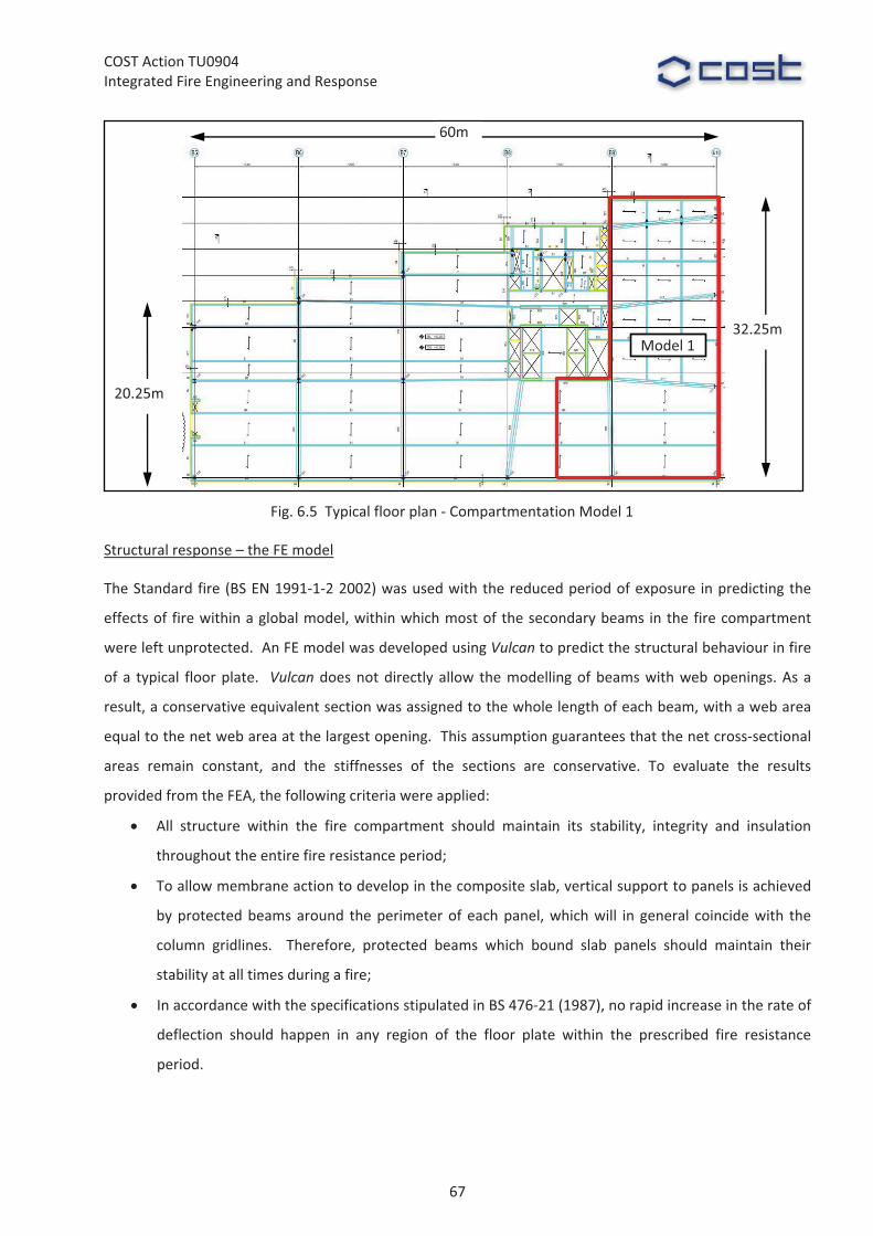
COST�Action�TU0904�Integrated�Fire�Engineering�and�Response�
�
�
Structural�response�–�the�FE�model�
The�Standard�fire�(BS�EN�1991�1�2�2002)�was�used�with�the�reduced�period�of�exposure� in�predicting�the�
effects�of� fire�within�a�global�model,�within�which�most�of�the�secondary�beams� in�the�fire�compartment�
were�left�unprotected.��An�FE�model�was�developed�using�Vulcan�to�predict�the�structural�behaviour�in�fire�
of�a� typical� floor�plate.� �Vulcan� does�not�directly�allow� the�modelling�of�beams�with�web�openings.�As�a�
result,�a�conservative�equivalent�section�was�assigned�to�the�whole�length�of�each�beam,�with�a�web�area�
equal�to�the�net�web�area�at�the�largest�opening.��This�assumption�guarantees�that�the�net�cross�sectional�
areas� remain� constant,� and� the� stiffnesses� of� the� sections� are� conservative.� To� evaluate� the� results�
provided�from�the�FEA,�the�following�criteria�were�applied:�
All� structure� within� the� fire� compartment� should� maintain� its� stability,� integrity� and� insulation�
throughout�the�entire�fire�resistance�period;��
To�allow�membrane�action�to�develop�in�the�composite�slab,�vertical�support�to�panels�is�achieved�
by�protected�beams�around� the�perimeter�of�each�panel,�which�will� in�general� coincide�with� the�
column� gridlines.� � Therefore,� protected� beams� which� bound� slab� panels� should� maintain� their�
stability�at�all�times�during�a�fire;�
In�accordance�with�the�specifications�stipulated�in�BS�476�21�(1987),�no�rapid�increase�in�the�rate�of�
deflection� should� happen� in� any� region� of� the� floor� plate� within� the� prescribed� fire� resistance�
period.�
Fig.�6.5��Typical�floor�plan�� Compartmentation�Model�1
Model�1�
60m
20.25m�
32.25m
67

COST�Action�TU0904�Integrated�Fire�Engineering�and�Response�
�
�
�
�
Fig.�6.6�shows�the�proposed�protection�strategy�for�the�fire�compartment.��Beams�are�12m�long,�with�most�
of� the� secondary� beams� left� unprotected,� while� all� the� main� perimeter� beams� and� columns� are� fully�
Fig.�6.7�Model�1��predicted�global�model�at�elevated�temperatures�
Protected�beam�B1�
Protected�beam�B2
Slab�S3�
Slab�S1
Slab�S2
Protected�beams�
Unprotected�beams
Concrete�core�
Concrete�core�
Protected�beams�
Unprotected�beams�
Fig.�6.6�Fire�protection�scheme�of�Model�1�
68

COST�Action�TU0904�Integrated�Fire�Engineering�and�Response�
protected.��The�heating�regime�in�this�Standard�fire�analysis�is�based�on�the�assumption�that�the�protected�
steel�columns�will�reach�a�maximum�temperature�of�about�550°C�at�the�end�of�the�fire�resistance�period.�
This� is� based� on� the� prescriptive�UK� requirements� for� fire� resistance� (ASFP� 2010).� Beams�which� contain�
openings�have� structural� failure�modes�which� are� very�different� from� those�of� normal� solid�web�beams;�
therefore,� separate� fire� resistance� checks�were� carried� out� to� provide� the� limiting� temperatures� for� any�
section�design,�taking�account�of�the�nature�of�the�critical�stresses.�
Outcomes�of�numerical�modelling�
Fig.�6.7�shows�the�predicted�global�fire�behaviour�of�the�numerical�model.�The�mid�span�deflections�of�the�
unprotected�concrete�slab�panels�(S1,�S2�and�S3)�and�the�protected�beams�(B1�and�B2)�are�presented�in�Fig.�
6.8.� �None�of�the�slab�panels�suffer�from�the�loss�of�strength�of�the�unprotected�secondary�beams�at�the�
end�of�60�minutes’�fire�exposure.��No�runaway�structural�failure�was�observed�in�the�beams�or�slabs.��
�
�
6.3�CONCLUSION�
A�detailed�FEA�of�the�structure�within�a�compartment�was�carried�out�to�predict�the�global�behaviour�of�the�
structure� under� exposure� to� a� Standard� fire.� It� was� clearly� demonstrated� that� the� performance�based�
structural� fire� engineering� solution� is� able� to� provide� an� efficient� way� of� increasing� the� accuracy� of�
modelling� of� the� real� structural� behaviour� in� fire.� The� performance�based� approach� showed� that�
strategically� placed� passive� fire� protection� for� a� composite� office� building� can� satisfy� the� functional�
Fig.�6.8�Mid�span�deflection
� 450
� 400
� 350
� 300
� 250
� 200
� 150
� 100
� 50
00 10 20 30 40 50 60
Deflection�[m
m]
Time�[min]
Protected�beam�B1
Protected�beam�B2�
Slab�S3�
Slab�S1� Slab�S2�
Span/30�
69
COST�Action�TU0904�Integrated�Fire�Engineering�and�Response�
requirements�of�England�and�Wales�Building�Regulations,�as�well�as�leading�to�savings�on�the�project�cost�
by�optimising�the�requirement�for�passive�structural�steel�fire�protection.�
�
References�
ADB�(2006),�“Approved�Document�B���Fire�Safety,�2006�Edition”.�The�Stationery�Office�Ltd,�London,�UK.�ASFP�(2010),�“Fire�Protection�for�Structural�Steel�in�Buildings�(The�Yellow�Book)”,�4th�Edition,�Association�for�
Specialist�Fire�Protection,�2010.��Bailey,�C.�G.�and�Moore,�D.�B.�(2000a)�“The�structural�behaviour�of�steel�frames�with�composite�floor�slabs�
subject�to�fire:�Part�1:�Theory”,�The�Structural�Engineer�78�(11),�19�27�Bailey,�C.�G.�and�Moore,�D.�B.�(2000b)�“The�structural�behaviour�of�steel�frames�with�composite�floor�slabs�
subject�to�fire:�Part�2:�Design”,�The�Structural�Engineer�78�(11),�28�33�BS� EN� 12845� (2004)� +� A2� (2009),� “Fixed� Firefighting� Systems.� Automatic� Sprinkler� Systems,� Design,�
Installation�And�Maintenance”,�British�Standards�Institution,�London,�UK.�BS�EN�1991�1�2�(2002),�“Eurocode�1:�Actions�on�Structures.�General�Actions.�Actions�on�Structures�Exposed�
to�Fire”,�British�Standards�Institution,�London,�UK.�BS� 476�21� (1987),� “Fire� tests� on� building�materials� and� structures.�Method� for� determination� of� the� fire�
resistance�of�loadbearing�elements�of�construction”,�British�Standards�Institution,�London,�UK.�Building�Regulations�(2000),�“The�Building�Regulations�for�England�and�Wales”,�The�Stationery�Office�Ltd,�
London,�UK.�LDSA�(1997),�“Fire�Safety�Guide�No�1���Section�20�Buildings”,�The�London�District�Surveyors’�Association.�Newman,�G.M.,�Robinson,� J.T.�and�Bailey�C.G.� (2006),�“Fire�Safe�Design:�A�New�Approach�to�Multi�Storey�
Steel�Framed�Buildings”,�SCI�Publication�P288,�Second�edition,�The�Steel�Construction�Institute,�UK.�PD�6688�1�2�(2007),�“Published�Document���Background�Paper�to�the�UK�National�Annex�to�BS�EN�1991�1�
2”,�British�Standards�Institution,�London,�UK.�Vulcan�(2005),�Vulcan�Solutions�Limited�website:�www.vulcan�solutions.com.��
70