Embed Size (px)
Citation preview
1Angel: Interactive Computer Graphics 4E © Addison-Wesley 2005
Chapter 6: Shading
Ed Angel
Professor of Computer Science, Electrical and Computer
Engineering, and Media Arts
University of New Mexico
2Angel: Interactive Computer Graphics 4E © Addison-Wesley 2005
Objectives
• Learn to shade objects so their images appear three-dimensional
• Introduce the types of light-material interactions
• Build a simple reflection model---the Phong model--- that can be used with real time graphics hardware
3Angel: Interactive Computer Graphics 4E © Addison-Wesley 2005
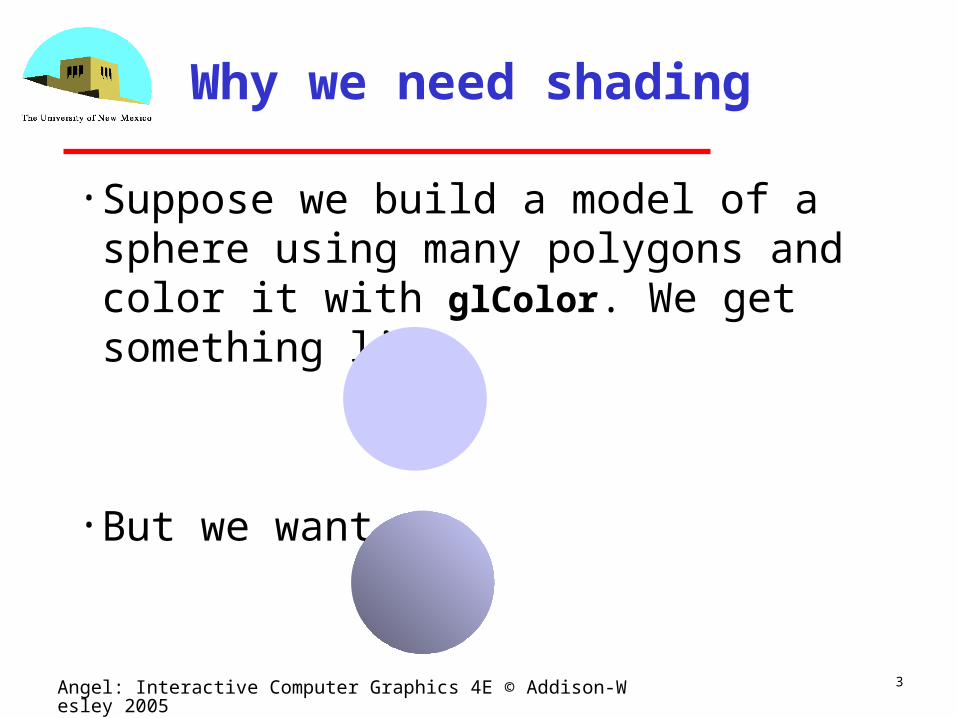
Why we need shading
• Suppose we build a model of a sphere using many polygons and color it with glColor. We get something like
• But we want
4Angel: Interactive Computer Graphics 4E © Addison-Wesley 2005
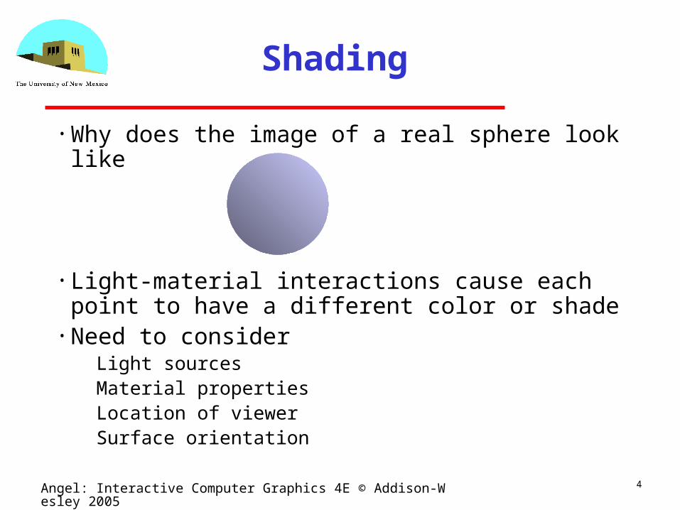
Shading
• Why does the image of a real sphere look like
• Light-material interactions cause each point to have a different color or shade
• Need to consider Light sources Material properties Location of viewer Surface orientation
5Angel: Interactive Computer Graphics 4E © Addison-Wesley 2005
Scattering
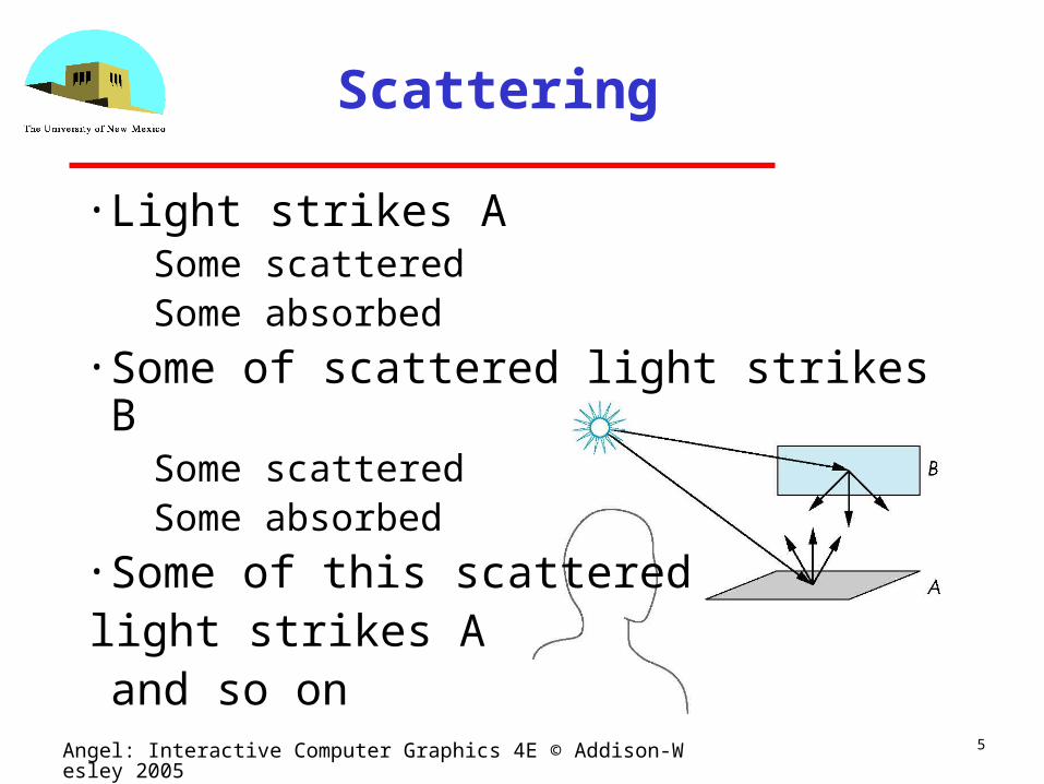
• Light strikes A Some scattered Some absorbed
• Some of scattered light strikes B Some scattered Some absorbed
• Some of this scatteredlight strikes Aand so on
6Angel: Interactive Computer Graphics 4E © Addison-Wesley 2005
Rendering Equation
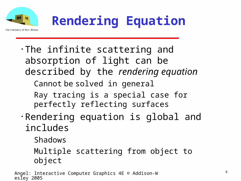
• The infinite scattering and absorption of light can be described by the rendering equation
Cannot be solved in general
Ray tracing is a special case for perfectly reflecting surfaces
• Rendering equation is global and includes Shadows
Multiple scattering from object to object
7Angel: Interactive Computer Graphics 4E © Addison-Wesley 2005
Global Effects
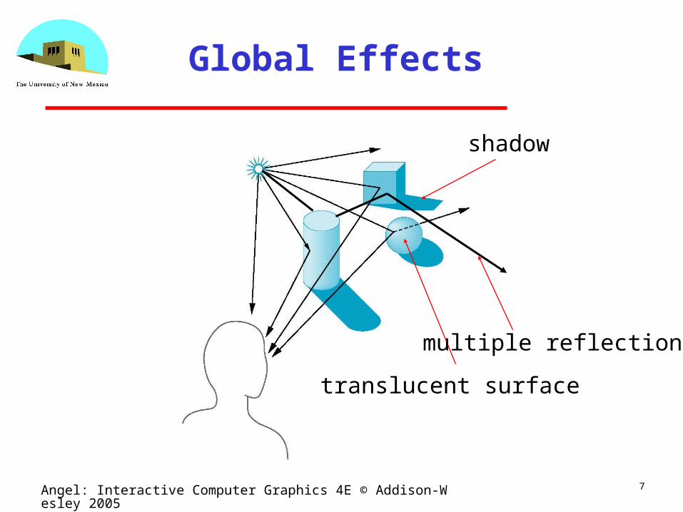
translucent surface
shadow
multiple reflection
8Angel: Interactive Computer Graphics 4E © Addison-Wesley 2005
Local vs Global Rendering
• Correct shading requires a global calculation involving all objects and light sources
Incompatible with pipeline model which shades each polygon independently (local rendering)
• However, in computer graphics, especially real time graphics, we are happy if things “look right”
Exist many techniques for approximating global effects
9Angel: Interactive Computer Graphics 4E © Addison-Wesley 2005
Light-Material Interaction
• Light that strikes an object is partially absorbed and partially scattered (reflected)
• The amount reflected determines the color and brightness of the object
A surface appears red under white light because the red component of the light is reflected and the rest is absorbed
• The reflected light is scattered in a manner that depends on the smoothness and orientation of the surface
10Angel: Interactive Computer Graphics 4E © Addison-Wesley 2005
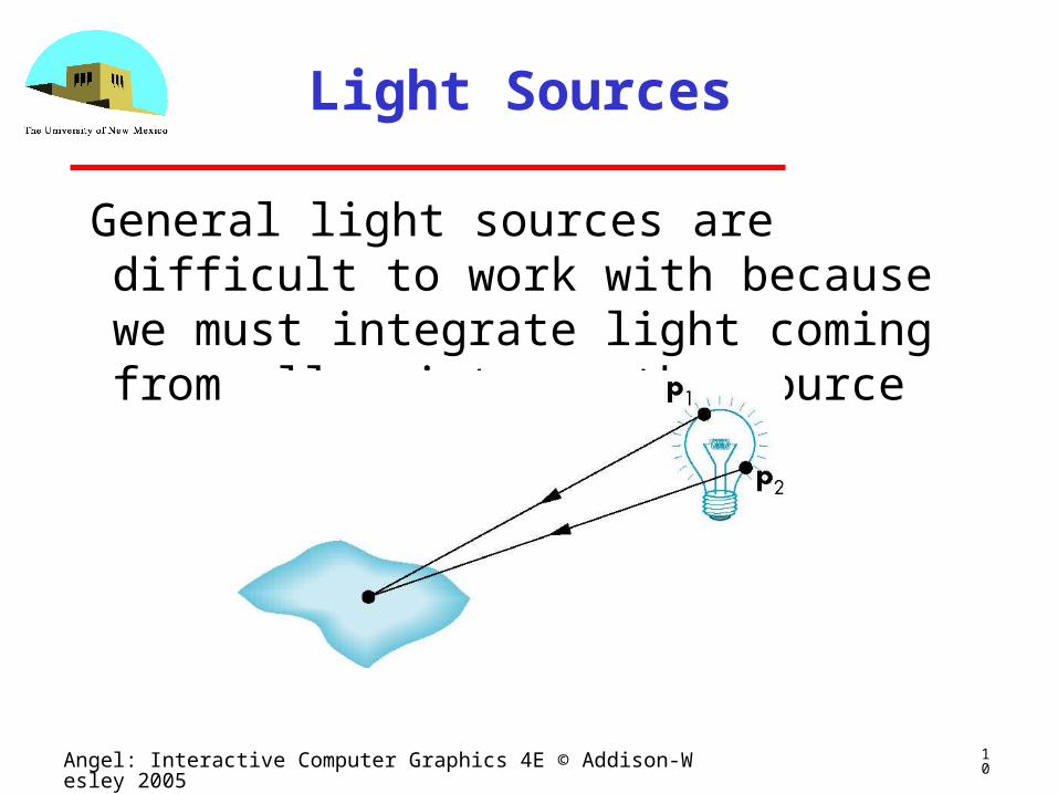
Light Sources
General light sources are difficult to work with because we must integrate light coming from all points on the source
11Angel: Interactive Computer Graphics 4E © Addison-Wesley 2005
Simple Light Sources
• Point source Model with position and color
Distant source = infinite distance away (parallel)
• Spotlight Restrict light from ideal point source
• Ambient light Same amount of light everywhere in scene
Can model contribution of many sources and reflecting surfaces
12Angel: Interactive Computer Graphics 4E © Addison-Wesley 2005
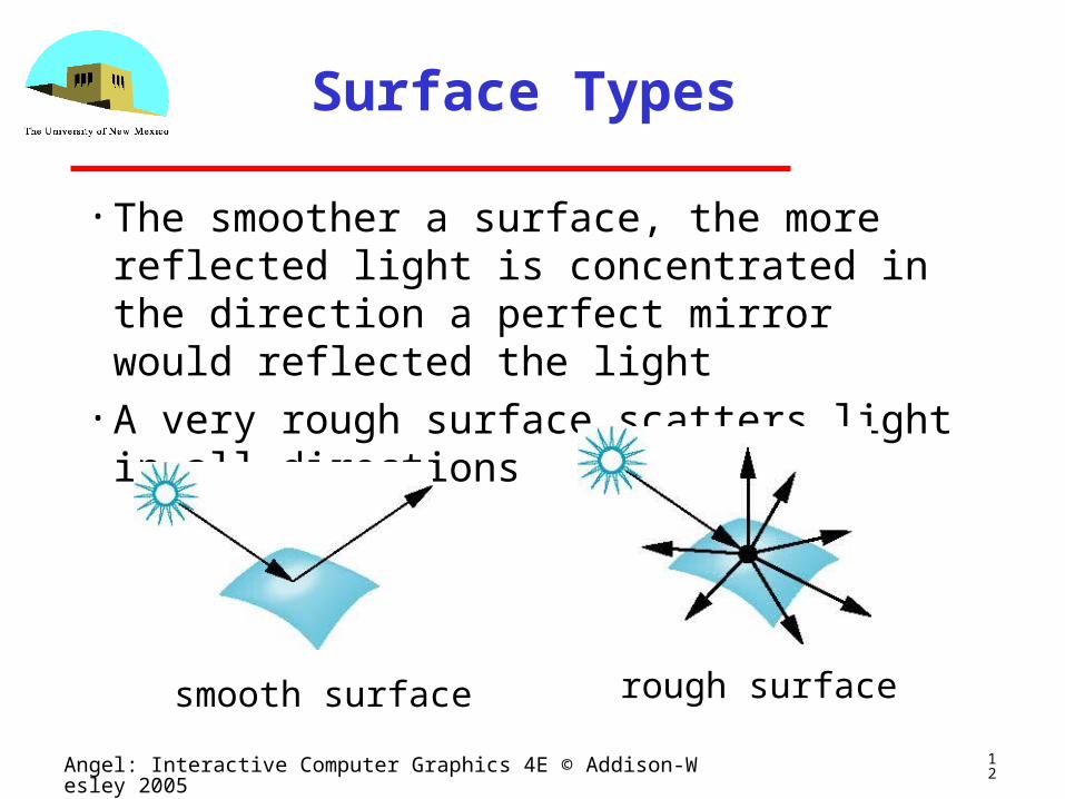
Surface Types
• The smoother a surface, the more reflected light is concentrated in the direction a perfect mirror would reflected the light
• A very rough surface scatters light in all directions
smooth surface rough surface
13Angel: Interactive Computer Graphics 4E © Addison-Wesley 2005
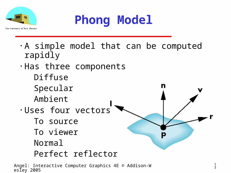
Phong Model
• A simple model that can be computed rapidly• Has three components
Diffuse Specular Ambient
• Uses four vectors To source To viewer Normal Perfect reflector
14Angel: Interactive Computer Graphics 4E © Addison-Wesley 2005
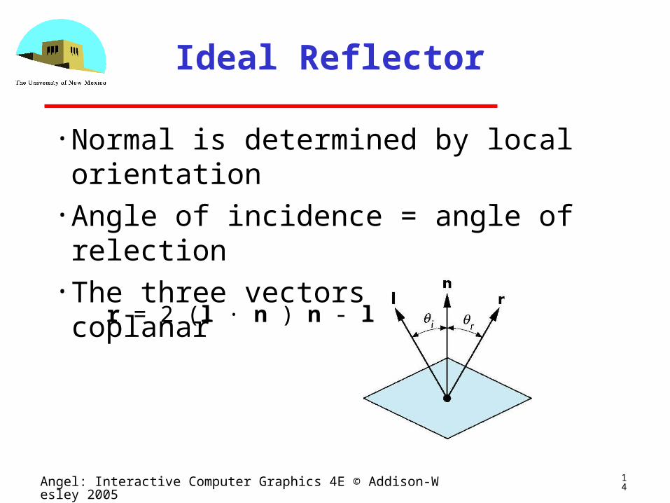
Ideal Reflector
• Normal is determined by local orientation• Angle of incidence = angle of relection• The three vectors must be coplanar
r = 2 (l · n ) n - l
15Angel: Interactive Computer Graphics 4E © Addison-Wesley 2005
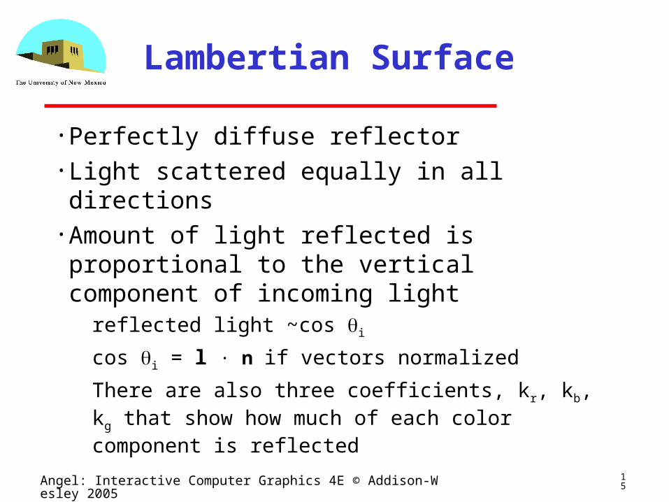
Lambertian Surface
• Perfectly diffuse reflector• Light scattered equally in all directions• Amount of light reflected is proportional to the vertical component of incoming light
reflected light ~cos i
cos i = l · n if vectors normalized
There are also three coefficients, kr, kb, kg that show how much of each color component is reflected
16Angel: Interactive Computer Graphics 4E © Addison-Wesley 2005
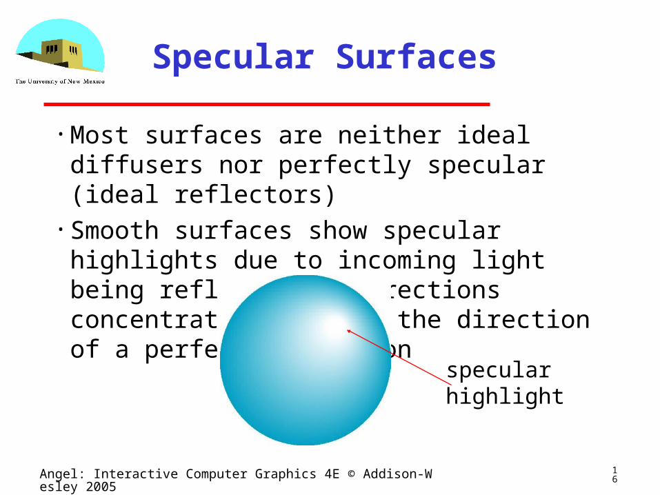
Specular Surfaces
• Most surfaces are neither ideal diffusers nor perfectly specular (ideal reflectors)
• Smooth surfaces show specular highlights due to incoming light being reflected in directions concentrated close to the direction of a perfect reflection
specularhighlight
17Angel: Interactive Computer Graphics 4E © Addison-Wesley 2005
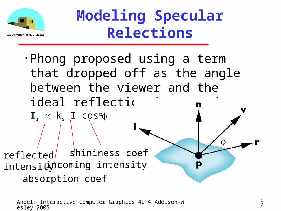
Modeling Specular Relections
• Phong proposed using a term that dropped off as the angle between the viewer and the ideal reflection increased
Ir ~ ks I cos
shininess coef
absorption coef
incoming intensityreflectedintensity
18Angel: Interactive Computer Graphics 4E © Addison-Wesley 2005
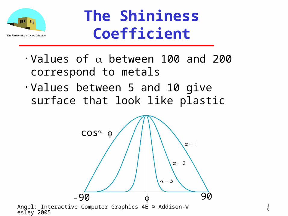
The Shininess Coefficient
• Values of between 100 and 200 correspond to metals
• Values between 5 and 10 give surface that look like plastic
cos
90-90
19Angel: Interactive Computer Graphics 4E © Addison-Wesley 2005
Shading II
Ed Angel
Professor of Computer Science, Electrical and Computer
Engineering, and Media Arts
University of New Mexico
20Angel: Interactive Computer Graphics 4E © Addison-Wesley 2005
Objectives
• Continue discussion of shading• Introduce modified Phong model• Consider computation of required vectors
21Angel: Interactive Computer Graphics 4E © Addison-Wesley 2005
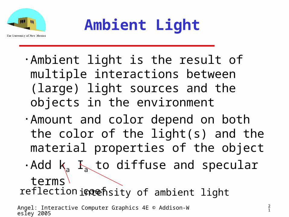
Ambient Light
• Ambient light is the result of multiple interactions between (large) light sources and the objects in the environment
• Amount and color depend on both the color of the light(s) and the material properties of the object
• Add ka Ia to diffuse and specular terms
reflection coef intensity of ambient light
22Angel: Interactive Computer Graphics 4E © Addison-Wesley 2005
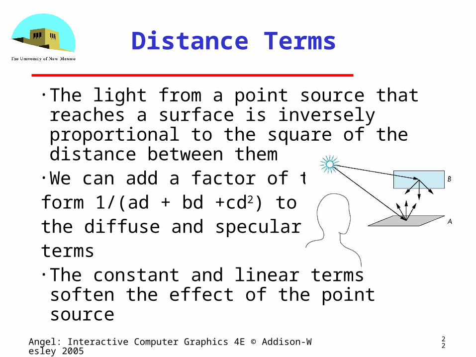
Distance Terms
• The light from a point source that reaches a surface is inversely proportional to the square of the distance between them
• We can add a factor of theform 1/(ad + bd +cd2) tothe diffuse and specular terms• The constant and linear terms soften the effect of the point source
23Angel: Interactive Computer Graphics 4E © Addison-Wesley 2005
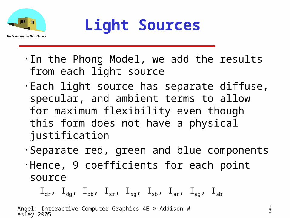
Light Sources
• In the Phong Model, we add the results from each light source
• Each light source has separate diffuse, specular, and ambient terms to allow for maximum flexibility even though this form does not have a physical justification
• Separate red, green and blue components• Hence, 9 coefficients for each point source
Idr, Idg, Idb, Isr, Isg, Isb, Iar, Iag, Iab
24Angel: Interactive Computer Graphics 4E © Addison-Wesley 2005
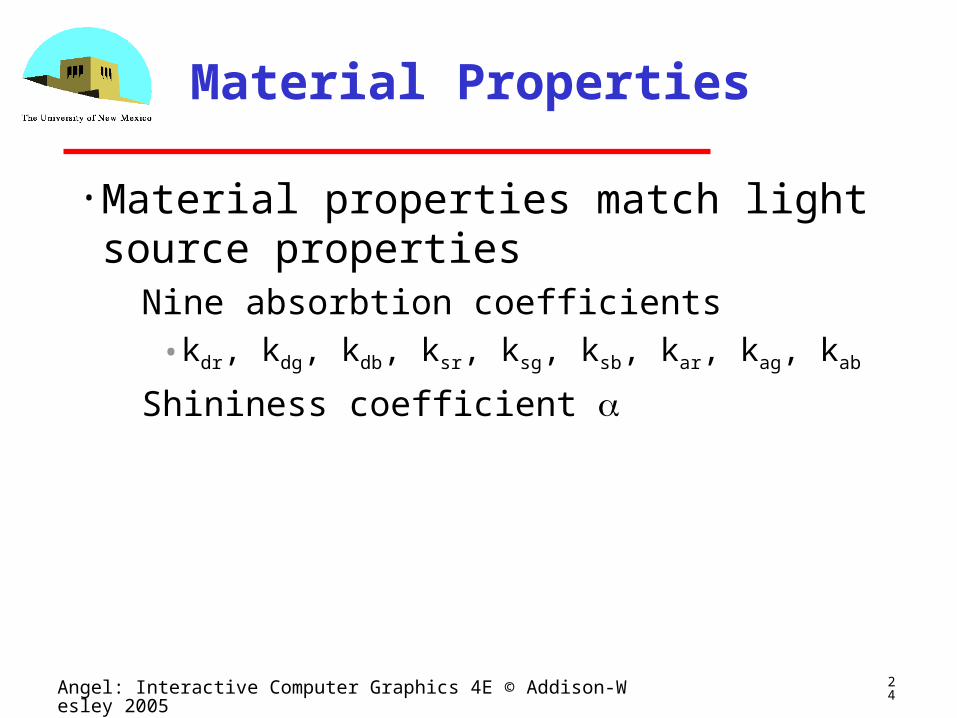
Material Properties
• Material properties match light source properties
Nine absorbtion coefficients• kdr, kdg, kdb, ksr, ksg, ksb, kar, kag, kab
Shininess coefficient
25Angel: Interactive Computer Graphics 4E © Addison-Wesley 2005
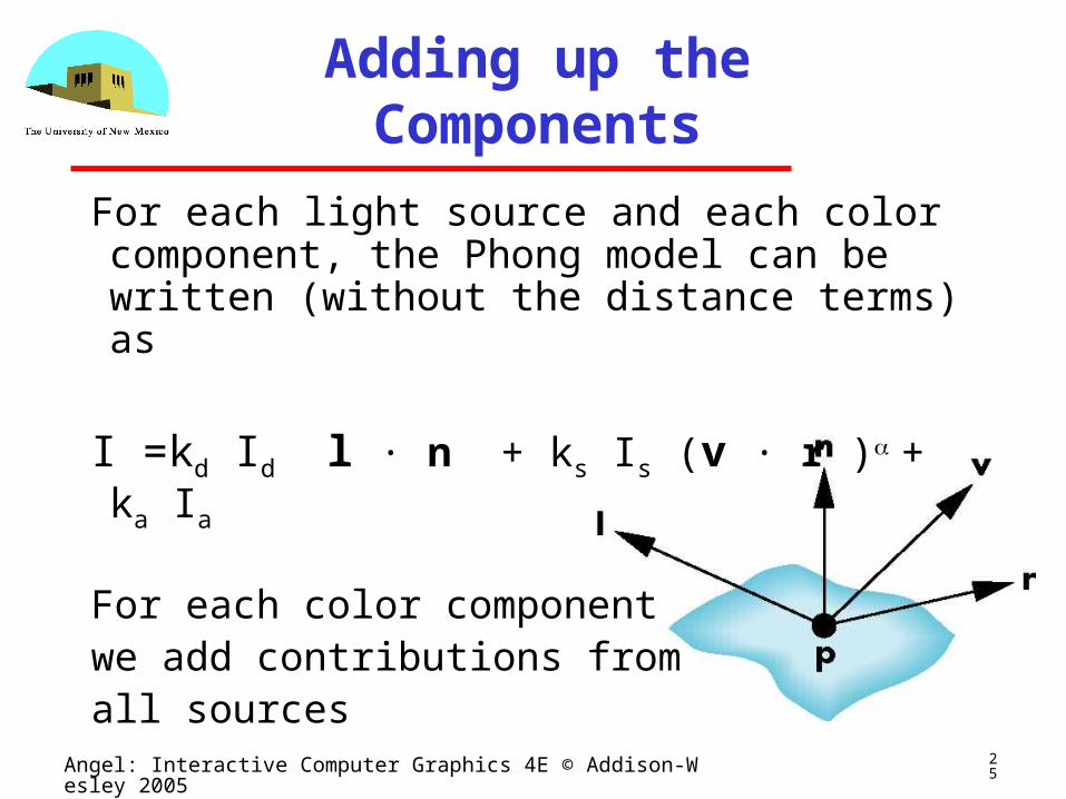
Adding up the Components
For each light source and each color component, the Phong model can be written (without the distance terms) as
I =kd Id l · n + ks Is (v · r )+ ka Ia
For each color componentwe add contributions fromall sources
26Angel: Interactive Computer Graphics 4E © Addison-Wesley 2005
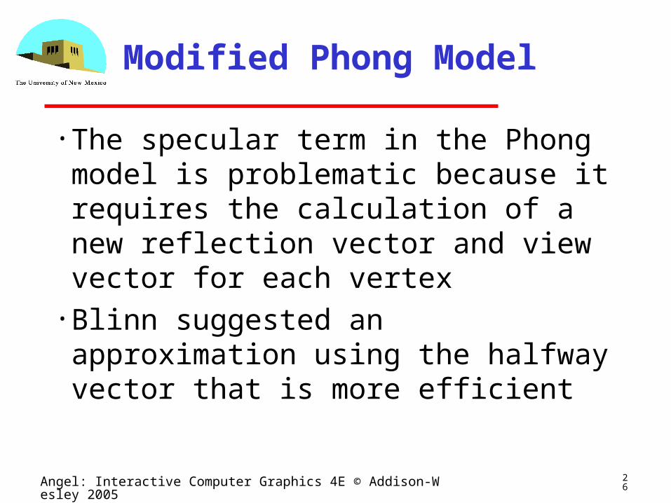
Modified Phong Model
• The specular term in the Phong model is problematic because it requires the calculation of a new reflection vector and view vector for each vertex
• Blinn suggested an approximation using the halfway vector that is more efficient
27Angel: Interactive Computer Graphics 4E © Addison-Wesley 2005
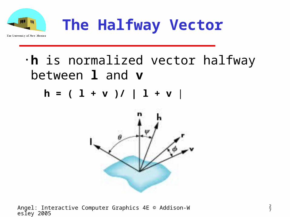
The Halfway Vector
• h is normalized vector halfway between l and v
h = ( l + v )/ | l + v |
28Angel: Interactive Computer Graphics 4E © Addison-Wesley 2005
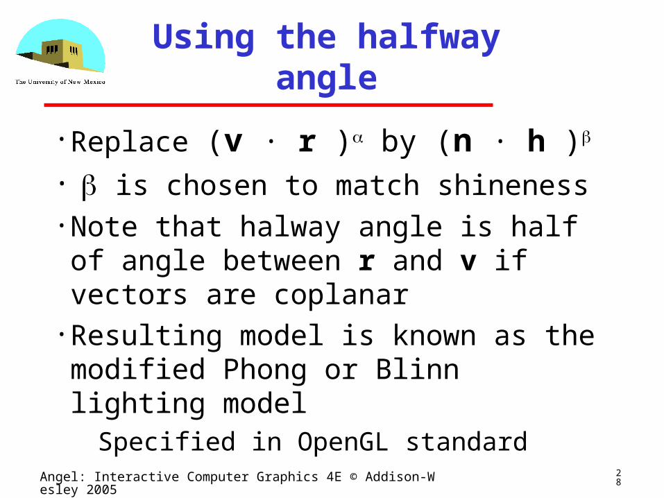
Using the halfway angle
• Replace (v · r )by (n · h )
• is chosen to match shineness• Note that halway angle is half of angle between r and v if vectors are coplanar
• Resulting model is known as the modified Phong or Blinn lighting model Specified in OpenGL standard
29Angel: Interactive Computer Graphics 4E © Addison-Wesley 2005
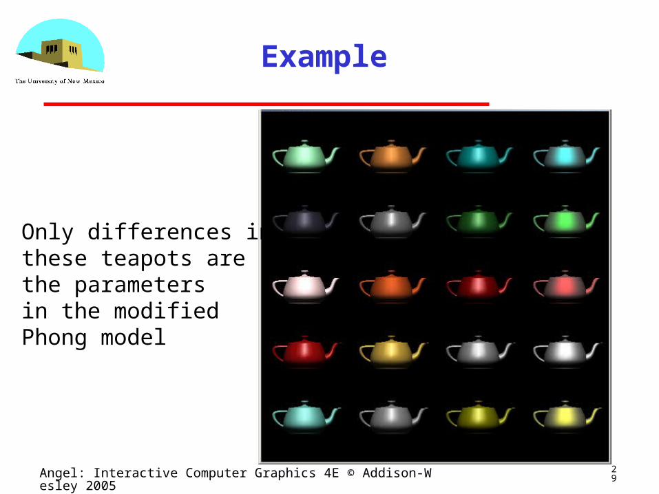
Example
Only differences in these teapots are the parametersin the modifiedPhong model
30Angel: Interactive Computer Graphics 4E © Addison-Wesley 2005
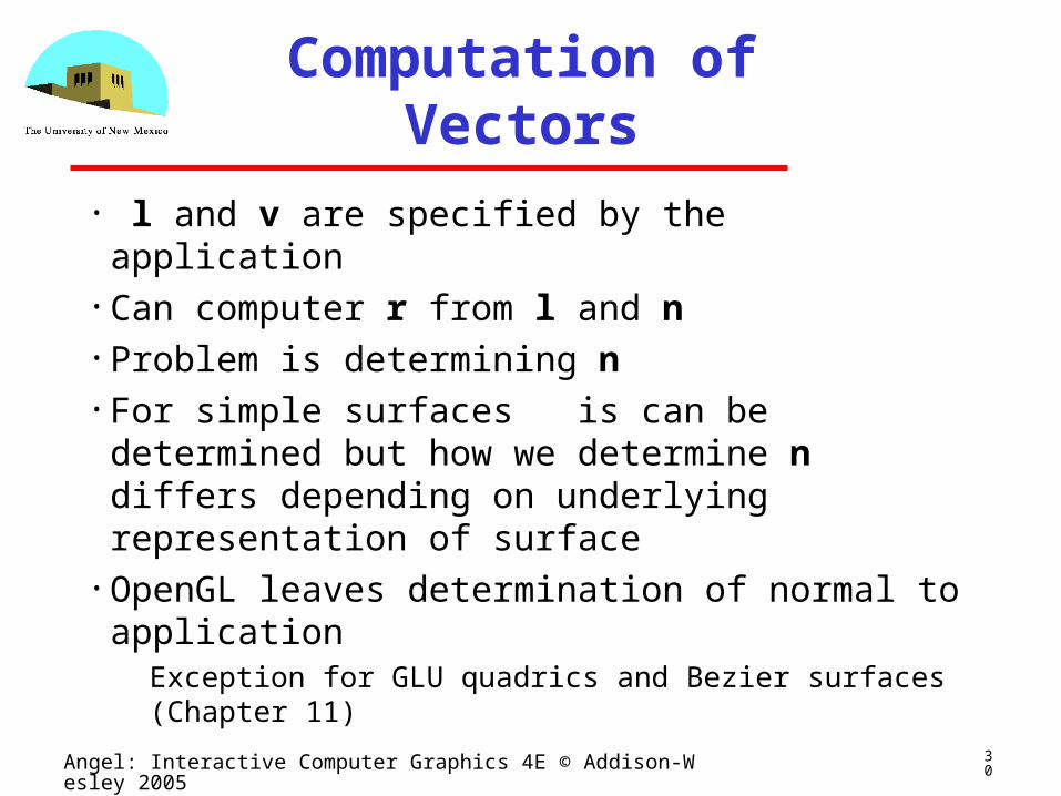
Computation of Vectors
• l and v are specified by the application• Can computer r from l and n• Problem is determining n• For simple surfaces is can be determined but
how we determine n differs depending on underlying representation of surface
• OpenGL leaves determination of normal to application
Exception for GLU quadrics and Bezier surfaces (Chapter 11)
31Angel: Interactive Computer Graphics 4E © Addison-Wesley 2005
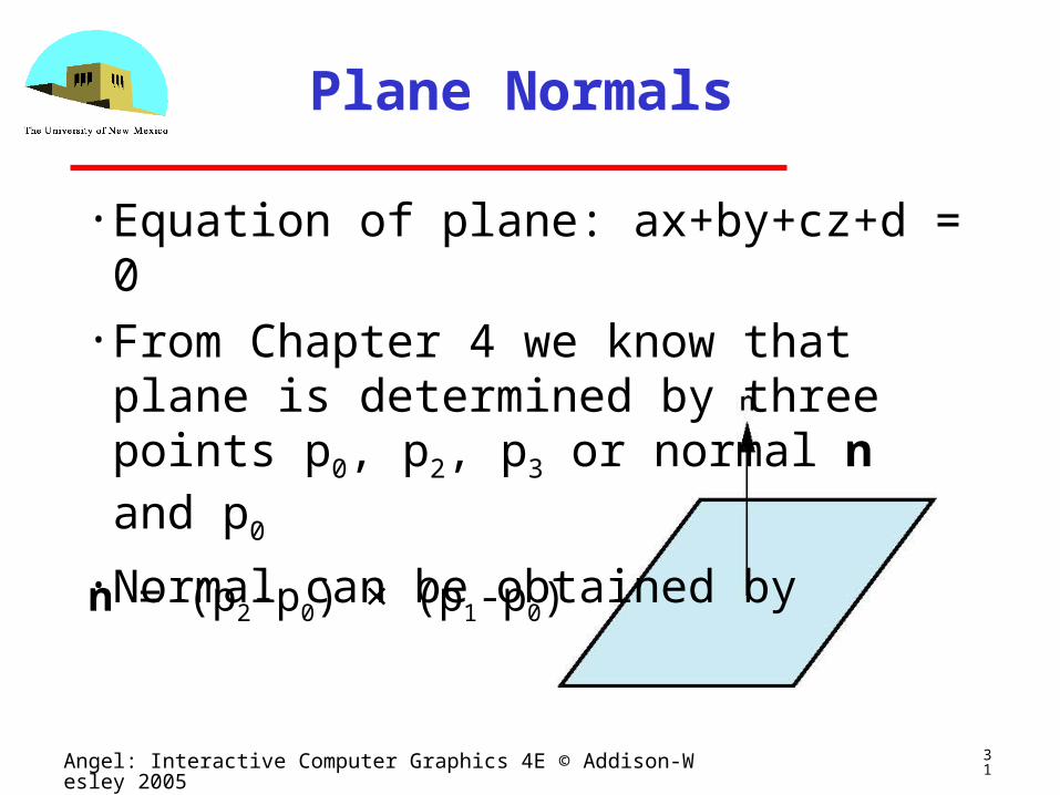
Plane Normals
• Equation of plane: ax+by+cz+d = 0• From Chapter 4 we know that plane is determined by three points p0, p2, p3 or normal n and p0
• Normal can be obtained by
n = (p2-p0) × (p1-p0)
32Angel: Interactive Computer Graphics 4E © Addison-Wesley 2005
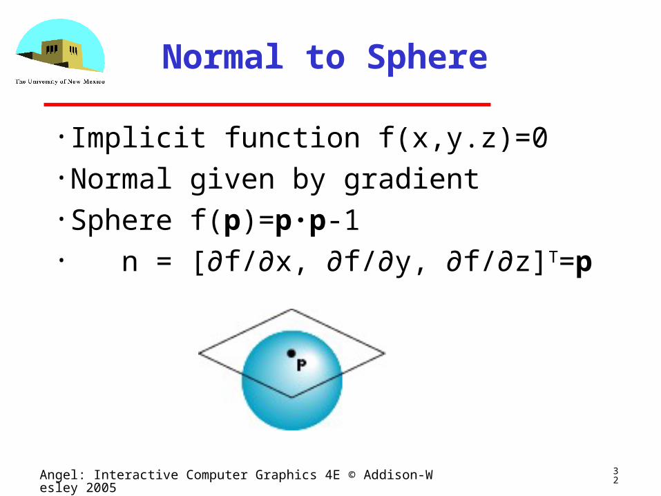
Normal to Sphere
• Implicit function f(x,y.z)=0• Normal given by gradient• Sphere f(p)=p·p-1• n = [∂f/∂x, ∂f/∂y, ∂f/∂z]T=p
33Angel: Interactive Computer Graphics 4E © Addison-Wesley 2005
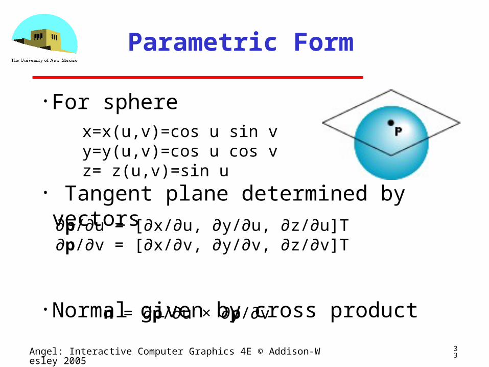
Parametric Form
• For sphere
• Tangent plane determined by vectors
• Normal given by cross product
x=x(u,v)=cos u sin vy=y(u,v)=cos u cos vz= z(u,v)=sin u
∂p/∂u = [∂x/∂u, ∂y/∂u, ∂z/∂u]T∂p/∂v = [∂x/∂v, ∂y/∂v, ∂z/∂v]T
n = ∂p/∂u × ∂p/∂v
34Angel: Interactive Computer Graphics 4E © Addison-Wesley 2005
General Case
• We can compute parametric normals for other simple cases
Quadrics
Parameteric polynomial surfaces• Bezier surface patches (Chapter 11)
35Angel: Interactive Computer Graphics 4E © Addison-Wesley 2005
Shading in OpenGL
Ed Angel
Professor of Computer Science, Electrical and Computer
Engineering, and Media Arts
University of New Mexico
36Angel: Interactive Computer Graphics 4E © Addison-Wesley 2005
Objectives
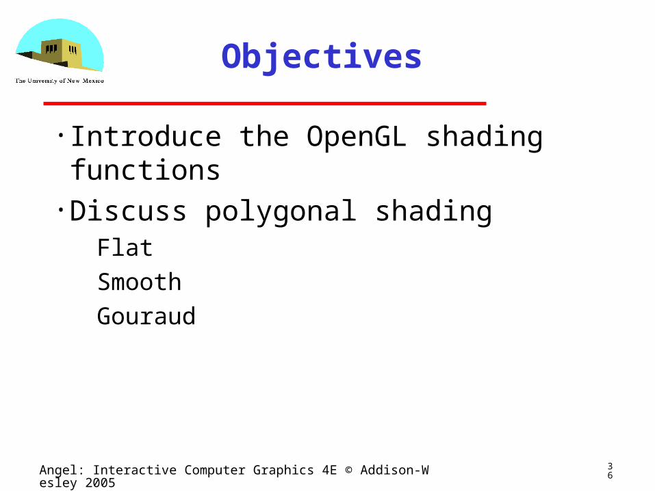
• Introduce the OpenGL shading functions• Discuss polygonal shading
Flat
Smooth
Gouraud
37Angel: Interactive Computer Graphics 4E © Addison-Wesley 2005
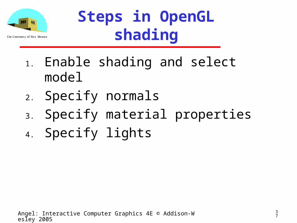
Steps in OpenGL shading
1. Enable shading and select model
2. Specify normals
3. Specify material properties
4. Specify lights
38Angel: Interactive Computer Graphics 4E © Addison-Wesley 2005
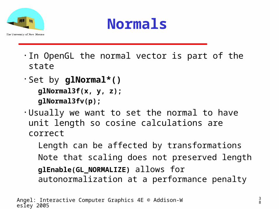
Normals
• In OpenGL the normal vector is part of the state• Set by glNormal*()
glNormal3f(x, y, z);glNormal3fv(p);
• Usually we want to set the normal to have unit length so cosine calculations are correct
Length can be affected by transformations
Note that scaling does not preserved lengthglEnable(GL_NORMALIZE) allows for
autonormalization at a performance penalty
39Angel: Interactive Computer Graphics 4E © Addison-Wesley 2005
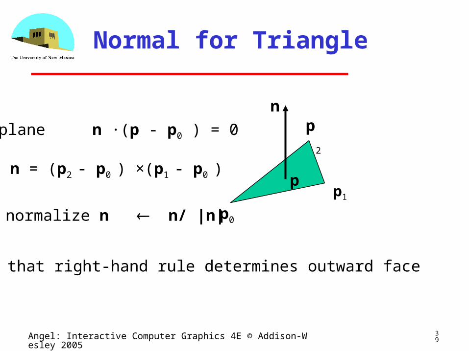
Normal for Triangle
p0
p1
p2
n
plane n ·(p - p0 ) = 0
n = (p2 - p0 ) ×(p1 - p0 )
normalize n n/ |n|
p
Note that right-hand rule determines outward face
40Angel: Interactive Computer Graphics 4E © Addison-Wesley 2005
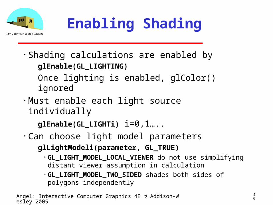
Enabling Shading
• Shading calculations are enabled byglEnable(GL_LIGHTING)
Once lighting is enabled, glColor() ignored• Must enable each light source individually
glEnable(GL_LIGHTi) i=0,1…..• Can choose light model parameters
glLightModeli(parameter, GL_TRUE)•GL_LIGHT_MODEL_LOCAL_VIEWER do not use
simplifying distant viewer assumption in calculation•GL_LIGHT_MODEL_TWO_SIDED shades both sides of
polygons independently
41Angel: Interactive Computer Graphics 4E © Addison-Wesley 2005
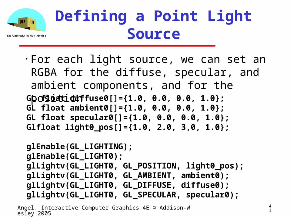
Defining a Point Light Source
• For each light source, we can set an RGBA for the diffuse, specular, and ambient components, and for the positionGL float diffuse0[]={1.0, 0.0, 0.0, 1.0};GL float ambient0[]={1.0, 0.0, 0.0, 1.0};GL float specular0[]={1.0, 0.0, 0.0, 1.0};Glfloat light0_pos[]={1.0, 2.0, 3,0, 1.0};
glEnable(GL_LIGHTING);glEnable(GL_LIGHT0);glLightv(GL_LIGHT0, GL_POSITION, light0_pos);glLightv(GL_LIGHT0, GL_AMBIENT, ambient0);glLightv(GL_LIGHT0, GL_DIFFUSE, diffuse0);glLightv(GL_LIGHT0, GL_SPECULAR, specular0);
42Angel: Interactive Computer Graphics 4E © Addison-Wesley 2005
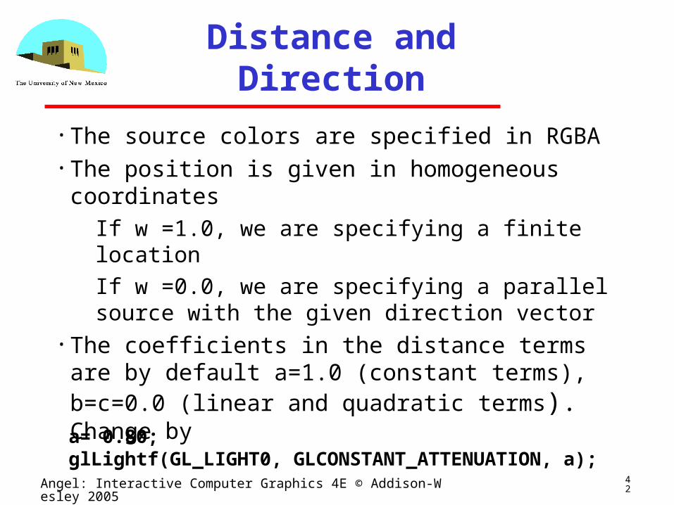
Distance and Direction
• The source colors are specified in RGBA• The position is given in homogeneous
coordinates If w =1.0, we are specifying a finite location
If w =0.0, we are specifying a parallel source with the given direction vector
• The coefficients in the distance terms are by default a=1.0 (constant terms), b=c=0.0 (linear and quadratic terms). Change bya= 0.80;glLightf(GL_LIGHT0, GLCONSTANT_ATTENUATION, a);
43Angel: Interactive Computer Graphics 4E © Addison-Wesley 2005
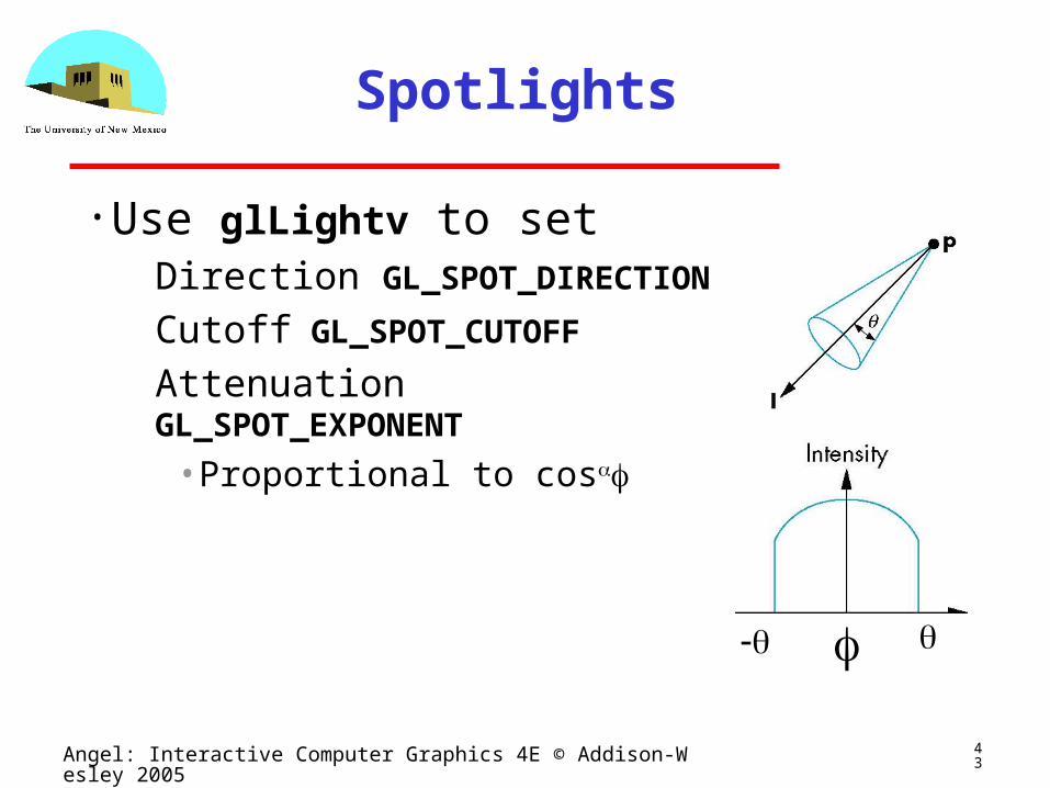
Spotlights
• Use glLightv to set Direction GL_SPOT_DIRECTION Cutoff GL_SPOT_CUTOFF Attenuation GL_SPOT_EXPONENT
• Proportional to cos
44Angel: Interactive Computer Graphics 4E © Addison-Wesley 2005
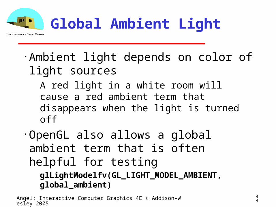
Global Ambient Light
• Ambient light depends on color of light sources
A red light in a white room will cause a red ambient term that disappears when the light is turned off
• OpenGL also allows a global ambient term that is often helpful for testingglLightModelfv(GL_LIGHT_MODEL_AMBIENT, global_ambient)
45Angel: Interactive Computer Graphics 4E © Addison-Wesley 2005
Moving Light Sources
• Light sources are geometric objects whose positions or directions are affected by the model-view matrix
• Depending on where we place the position (direction) setting function, we can
Move the light source(s) with the object(s)
Fix the object(s) and move the light source(s)
Fix the light source(s) and move the object(s)
Move the light source(s) and object(s) independently
46Angel: Interactive Computer Graphics 4E © Addison-Wesley 2005
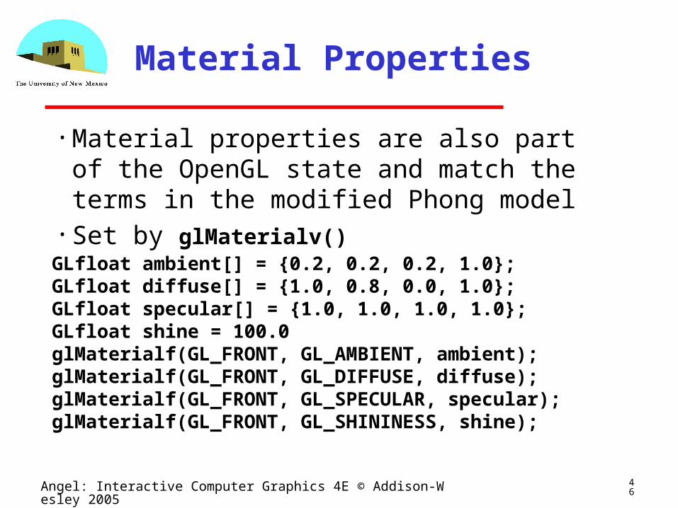
Material Properties
• Material properties are also part of the OpenGL state and match the terms in the modified Phong model
• Set by glMaterialv()GLfloat ambient[] = {0.2, 0.2, 0.2, 1.0};GLfloat diffuse[] = {1.0, 0.8, 0.0, 1.0};GLfloat specular[] = {1.0, 1.0, 1.0, 1.0};GLfloat shine = 100.0glMaterialf(GL_FRONT, GL_AMBIENT, ambient);glMaterialf(GL_FRONT, GL_DIFFUSE, diffuse);glMaterialf(GL_FRONT, GL_SPECULAR, specular);glMaterialf(GL_FRONT, GL_SHININESS, shine);
47Angel: Interactive Computer Graphics 4E © Addison-Wesley 2005
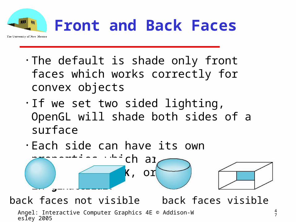
Front and Back Faces
• The default is shade only front faces which works correctly for convex objects
• If we set two sided lighting, OpenGL will shade both sides of a surface
• Each side can have its own properties which are set by using GL_FRONT, GL_BACK, or GL_FRONT_AND_BACK in glMaterialf
back faces not visible back faces visible
48Angel: Interactive Computer Graphics 4E © Addison-Wesley 2005
Emissive Term
• We can simulate a light source in OpenGL by giving a material an emissive component
• This component is unaffected by any sources or transformations
GLfloat emission[] = 0.0, 0.3, 0.3, 1.0);glMaterialf(GL_FRONT, GL_EMISSION, emission);
49Angel: Interactive Computer Graphics 4E © Addison-Wesley 2005
Transparency
• Material properties are specified as RGBA values
• The A value can be used to make the surface translucent
• The default is that all surfaces are opaque regardless of A
• Later we will enable blending and use this feature
50Angel: Interactive Computer Graphics 4E © Addison-Wesley 2005
Efficiency
• Because material properties are part of the state, if we change materials for many surfaces, we can affect performance
• We can make the code cleaner by defining a material structure and setting all materials during initialization
• We can then select a material by a pointer
typedef struct materialStruct { GLfloat ambient[4]; GLfloat diffuse[4]; GLfloat specular[4]; GLfloat shineness;} MaterialStruct;
51Angel: Interactive Computer Graphics 4E © Addison-Wesley 2005
Polygonal Shading
• Shading calculations are done for each vertex
Vertex colors become vertex shades
• By default, vertex shades are interpolated across the polygonglShadeModel(GL_SMOOTH);
• If we use glShadeModel(GL_FLAT); the color at the first vertex will determine the shade of the whole polygon

52Angel: Interactive Computer Graphics 4E © Addison-Wesley 2005
Polygon Normals
• Polygons have a single normal Shades at the vertices as computed by the
Phong model can be almost same
Identical for a distant viewer (default) or if there is no specular component
• Consider model of sphere• Want different normals at
each vertex even though
this concept is not quite
correct mathematically
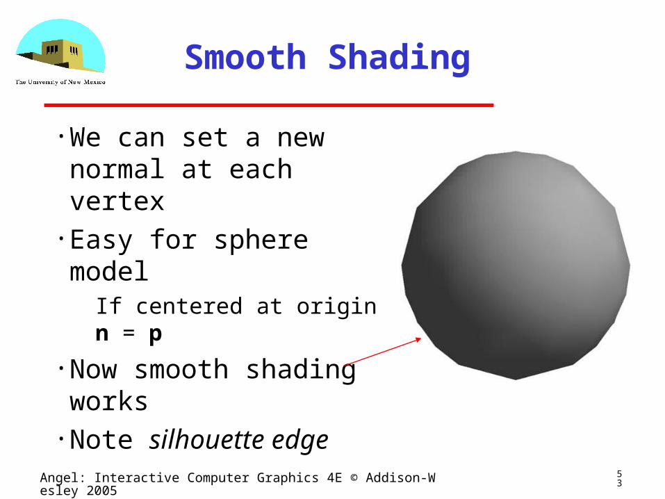
53Angel: Interactive Computer Graphics 4E © Addison-Wesley 2005
Smooth Shading
• We can set a new normal at each vertex
• Easy for sphere model If centered at origin n = p
• Now smooth shading works
• Note silhouette edge
54Angel: Interactive Computer Graphics 4E © Addison-Wesley 2005
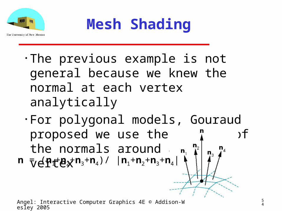
Mesh Shading
• The previous example is not general because we knew the normal at each vertex analytically
• For polygonal models, Gouraud proposed we use the average of the normals around a mesh vertex
n = (n1+n2+n3+n4)/ |n1+n2+n3+n4|
55Angel: Interactive Computer Graphics 4E © Addison-Wesley 2005
Gouraud and Phong Shading
• Gouraud Shading Find average normal at each vertex (vertex normals)
Apply modified Phong model at each vertex
Interpolate vertex shades across each polygon• Phong shading
Find vertex normals
Interpolate vertex normals across edges
Interpolate edge normals across polygon
Apply modified Phong model at each fragment
56Angel: Interactive Computer Graphics 4E © Addison-Wesley 2005
Comparison
• If the polygon mesh approximates surfaces with a high curvatures, Phong shading may look smooth while Gouraud shading may show edges
• Phong shading requires much more work than Gouraud shading
Until recently not available in real time systems
Now can be done using fragment shaders (see Chapter 9)
• Both need data structures to represent meshes so we can obtain vertex normals


![Shading in OpenGL · Polygonal Shading Light Source in OpenGL Material Properties in OpenGL Normal Vectors in OpenGL Approximating a Sphere [Angel 6.5-6.9] Polygonal Shading Light](https://img.pdfslide.us/doc/110x75/60b0a5eae15ec915e36c8c60/shading-in-opengl-polygonal-shading-light-source-in-opengl-material-properties-in.jpg)