Embed Size (px)
Citation preview
11
ANALYSIS OF UNISTRUT ANALYSIS OF UNISTRUT METAL FRAMING SYSTEMS METAL FRAMING SYSTEMS
USING GTSUSING GTS
2008 GTSUG2008 GTSUGLas Vegas, NV.Las Vegas, NV.
Chris Wandell, PEChris Wandell, PESenior Civil Senior Civil ConsultantConsultantJune 08June 08Powerpoint V.2003

22
Illustrate the GTS UNISTRUT AISI89 Illustrate the GTS UNISTRUT AISI89 Code Checking CapabilitiesCode Checking Capabilities
Provide an Example of a Palo Verde Provide an Example of a Palo Verde Nuclear Generating Station (PVNGS) Nuclear Generating Station (PVNGS) Application of the GTS UNISTRUT Application of the GTS UNISTRUT Code Checking FeatureCode Checking Feature
PRESENTATION’S PURPOSEPRESENTATION’S PURPOSE
33
PVNGS INTRODUCTION PVNGS INTRODUCTION
METAL FRAMING SYSTEMSMETAL FRAMING SYSTEMS
UNISTRUT SHAPESUNISTRUT SHAPES
UNISTRUT CONNECTIONSUNISTRUT CONNECTIONS
PVNGS ELECTRICAL RACEWAY PROJECTPVNGS ELECTRICAL RACEWAY PROJECT
GTS UNISTRUT CAPABILITIESGTS UNISTRUT CAPABILITIES
GTS UNISTRUT REQUESTSGTS UNISTRUT REQUESTS
QUESTIONS ?QUESTIONS ?
PRESENTATION OVERVIEWPRESENTATION OVERVIEW
44
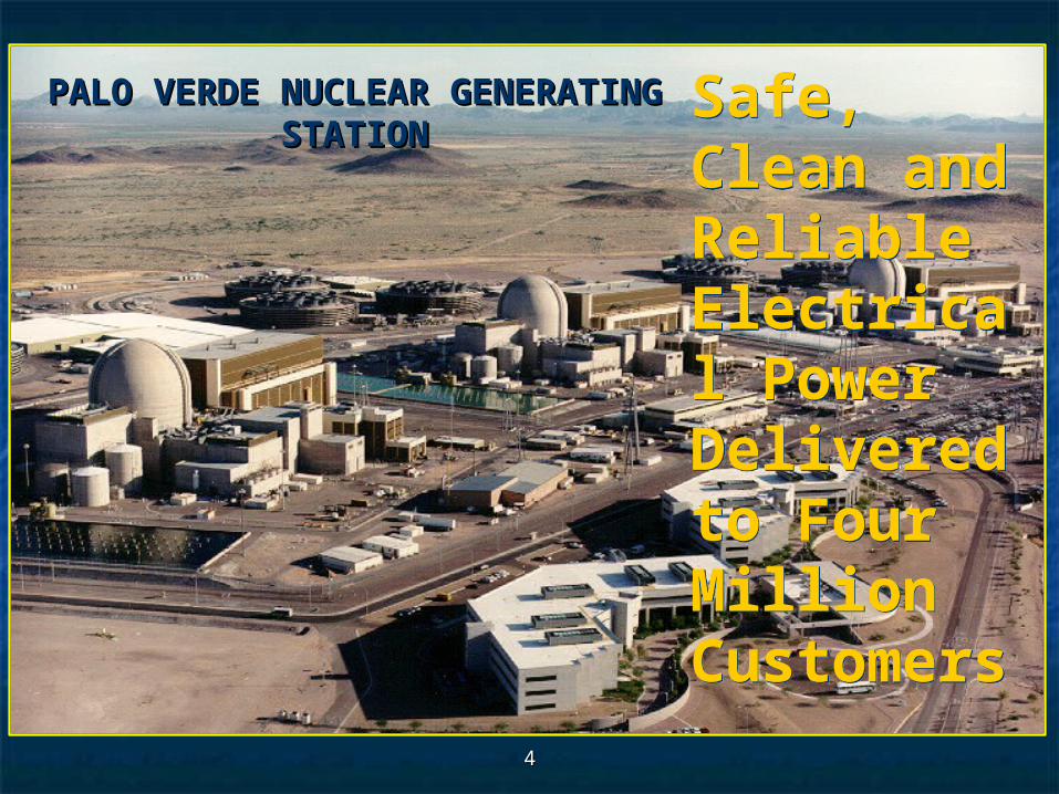
Safe, Clean and Reliable Electrical Power Delivered to Four Million Customers
Safe, Clean and Reliable Electrical Power Delivered to Four Million Customers
PALO VERDE NUCLEAR PALO VERDE NUCLEAR GENERATING STATIONGENERATING STATION
55
Located ≈ 50 miles west of Phoenix in Tonopah, Arizona Located ≈ 50 miles west of Phoenix in Tonopah, Arizona
9.5 years to License, Build and Commission 9.5 years to License, Build and Commission
Uses treated City of Phoenix sewage effluent for cooling water – Uses treated City of Phoenix sewage effluent for cooling water – 20 billion gallons/year20 billion gallons/year
$11 billion (1989) Dollar Investment$11 billion (1989) Dollar Investment
$6,000,000,000 Hardware$6,000,000,000 Hardware
$5,000,000,000 Interest/Financing$5,000,000,000 Interest/Financing
Over 2,000 employees; ≈ 300 engineersOver 2,000 employees; ≈ 300 engineers Owned by 7 UtilitiesOwned by 7 Utilities
Arizona Public Service: 29.1%, Salt River Project: 17.5%, Southern California Edison: 15.8%, El Arizona Public Service: 29.1%, Salt River Project: 17.5%, Southern California Edison: 15.8%, El Paso Electric: 15.8%, PNM: 10.2%, Southern California Public Power Authority: 5.9%, Paso Electric: 15.8%, PNM: 10.2%, Southern California Public Power Authority: 5.9%, Los Angeles Department of Water and Power: 5.7%Los Angeles Department of Water and Power: 5.7%
OperatedOperated by Arizona Public Service Company by Arizona Public Service Company (established: April 29, 1886 Japanese Immigrant Hutchlon Ohnick (established: April 29, 1886 Japanese Immigrant Hutchlon Ohnick granted a gas & electric service franchise Phoenix Illuminating Gas & granted a gas & electric service franchise Phoenix Illuminating Gas & Electric Light Co.)Electric Light Co.)
Palo Verde Nuclear Generating Palo Verde Nuclear Generating StationStation
66
8 8
CONTAINMENT SPRAY
Equipment Cooling
PolishingDemineralizers
8
CondensatePump
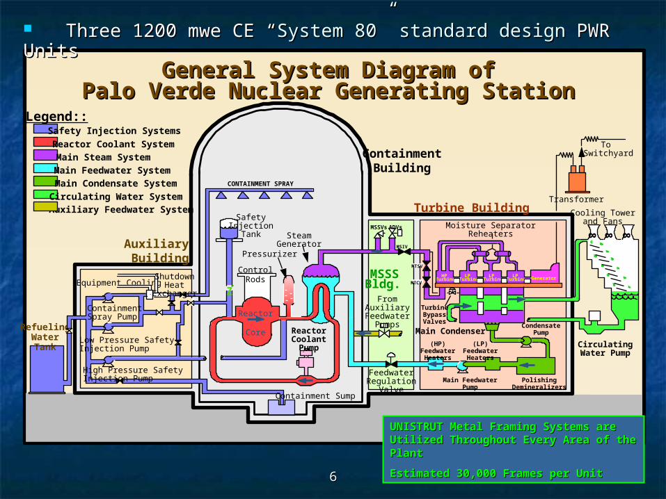
General System Diagram ofGeneral System Diagram ofPalo Verde Nuclear Generating StationPalo Verde Nuclear Generating Station
GeneratorLPTurbine
HPTurbine
LPTurbine
LPTurbine
MSSSBldg.
ADVs
MSIV
MSSVs
RefuelingWaterTank
ContainmentBuilding
Turbine Building
Z
MTSV
MTCV
Auxiliary Feedwater System
Safety Injection Systems
Legend::
Main Steam System
Main Feedwater System
Main Condensate System
Circulating Water System
Reactor Coolant System
AuxiliaryBuilding
ContainmentSpray Pump
Low Pressure SafetyInjection Pump
High Pressure SafetyInjection Pump
ShutdownHeat
Exchanger
SafetyInjection
Tank SteamGenerator
Pressurizer
ControlRods
Reactor
Core ReactorCoolantPump
FromAuxiliary
FeedwaterPumps
FeedwaterRegulation
ValveMain Feedwater
Pump
(HP)Feedwater
Heaters
(LP)Feedwater
Heaters
Main Condenser
Moisture SeparatorReheaters
TurbineBypassValves
CirculatingWater Pump
Cooling Towerand Fans
Transformer
To Switchyard
Containment Sump
Three 1200 mwe CE “Three 1200 mwe CE “System 80” standard design System 80” standard design PWR UnitsPWR Units
UNISTRUT Metal Framing Systems are UNISTRUT Metal Framing Systems are Utilized Throughout Every Area of the Utilized Throughout Every Area of the PlantPlant
Estimated 30,000 Frames per UnitEstimated 30,000 Frames per Unit

77
METAL STRUT FRAMING SYSTEMSMETAL STRUT FRAMING SYSTEMS Used at PVNGS to support Nuclear Seismic Category Used at PVNGS to support Nuclear Seismic Category
1/Safety-Related Electrical Raceway (Cabletray & Conduit), 1/Safety-Related Electrical Raceway (Cabletray & Conduit), Instruments, Small Bore Piping, Small Equipment etc …Instruments, Small Bore Piping, Small Equipment etc …
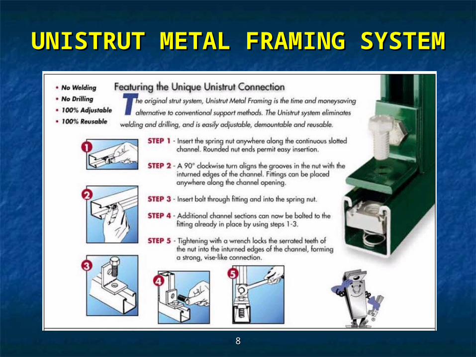
Consist of continuous-slot metal channels with in-turned lips Consist of continuous-slot metal channels with in-turned lips and associated hardware for fastening to the channels and associated hardware for fastening to the channels (Strut) at random points.(Strut) at random points.
Eliminates (minimizes) welding and drilling; is easily Eliminates (minimizes) welding and drilling; is easily adjustable, adjustable, de-mountable and re-usable.de-mountable and re-usable.
Metal Framing System Manufacturer’s: Metal Framing System Manufacturer’s: UNISTRUTUNISTRUT, Globe , Globe Strut, Strut, US Strut, B-Line, Flex-Strut, SuperStrut, PowerstrutUS Strut, B-Line, Flex-Strut, SuperStrut, Powerstrut
88
UNISTRUT METAL FRAMING UNISTRUT METAL FRAMING SYSTEMSYSTEM

99
Electrical Raceway Design ApplicationsElectrical Raceway Design Applications PVNGS UNISTRUT Raceway Supports Structures are field-PVNGS UNISTRUT Raceway Supports Structures are field-
installed in accordance with approved Engineering Designs.installed in accordance with approved Engineering Designs.
UNISTRUT METAL FRAMING UNISTRUT METAL FRAMING SYSTEMSYSTEM
1010
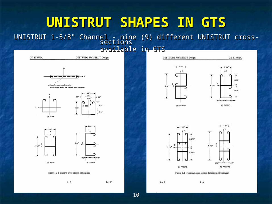
UNISTRUT SHAPES IN GTSUNISTRUT SHAPES IN GTSUNISTRUT 1-5/8UNISTRUT 1-5/8"" Channel - nine (9) different UNISTRUT cross-sections Channel - nine (9) different UNISTRUT cross-sections
available in GTSavailable in GTS

1111
UNISTRUT SHAPES IN GTSUNISTRUT SHAPES IN GTSUNISTRUT 1-5/8UNISTRUT 1-5/8"" Channel Channel
1212
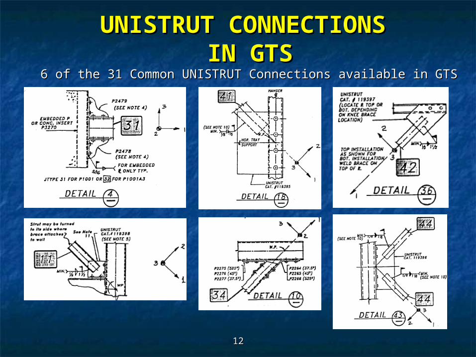
6 of the 31 Common UNISTRUT Connections available in GTS6 of the 31 Common UNISTRUT Connections available in GTS
UNISTRUT CONNECTIONS UNISTRUT CONNECTIONS IN GTSIN GTS

1313
PVNGS installed a fire protective material Thermo-Lag PVNGS installed a fire protective material Thermo-Lag 330-330-11 on electrical raceway systems from 1983 - 1987 on electrical raceway systems from 1983 - 1987
NRC Generic Letter 92.08 - Thermo-LagNRC Generic Letter 92.08 - Thermo-Lag fire endurance, fire endurance, ampacity, seismic integrity, quality and Quality Assurance ampacity, seismic integrity, quality and Quality Assurance Program vendor data suspectProgram vendor data suspect
PVNGS ELECTRICAL RACEWAY PVNGS ELECTRICAL RACEWAY PROJECTPROJECT
UNISTRUT capabilities developed UNISTRUT capabilities developed for PVNGS 1992for PVNGS 1992
Problem StatementProblem Statement: PVNGS Electrical Raceway System structural : PVNGS Electrical Raceway System structural evaluations were based on an under-estimated weight of fire evaluations were based on an under-estimated weight of fire protection material (Thermo-lag 330-1)protection material (Thermo-lag 330-1)
Project PurposeProject Purpose: evaluate impact of as-built Thermo-lag Protective : evaluate impact of as-built Thermo-lag Protective Envelope (TPE) weight on electrical raceway (conduit)Envelope (TPE) weight on electrical raceway (conduit)

1414
PVNGS committed to determine installed as-built weight of PVNGS committed to determine installed as-built weight of Thermo-Lag. Average weight per square foot, 1-hr fire barrier, Thermo-Lag. Average weight per square foot, 1-hr fire barrier, TPE (thickness 0.80"; density 71 lbs/ftTPE (thickness 0.80"; density 71 lbs/ft33) = 4.73 lbs/ft) = 4.73 lbs/ft22
Resultant over-weight conduit following incorporation of Resultant over-weight conduit following incorporation of Thermo-lag data into raceway weight tracking databaseThermo-lag data into raceway weight tracking database
Unit-1 = 787 overweight conduit runsUnit-1 = 787 overweight conduit runs
Unit-2 = 578 overweight conduit runsUnit-2 = 578 overweight conduit runs
Unit-3 = 449 overweight conduit runsUnit-3 = 449 overweight conduit runs
PVNGS ELECTRICAL RACEWAY PVNGS ELECTRICAL RACEWAY PROJECTPROJECT

1515
70' Auxiliary Building: Largest T-lag enclosure, Long run of T-lag along the south wall – Appendix-R, 3-hour, U13.
PVNGS ELECTRICAL RACEWAY PVNGS ELECTRICAL RACEWAY PROJECTPROJECT
Thermo-lagThermo-lagEnclosed Conduit Enclosed Conduit SystemsSystems
(5) 4” Dia. (5) 4” Dia. ConduitConduit
Conduit Conduit SupportSupport

1616
PVNGS ELECTRICAL RACEWAY PVNGS ELECTRICAL RACEWAY PROJECTPROJECT
70' Auxiliary Building
Conduit Conduit SupportsSupports

1717
PVNGS ELECTRICAL RACEWAY PVNGS ELECTRICAL RACEWAY PROJECTPROJECT
70' Auxiliary Building
Conduit Conduit SupportSupport
1818
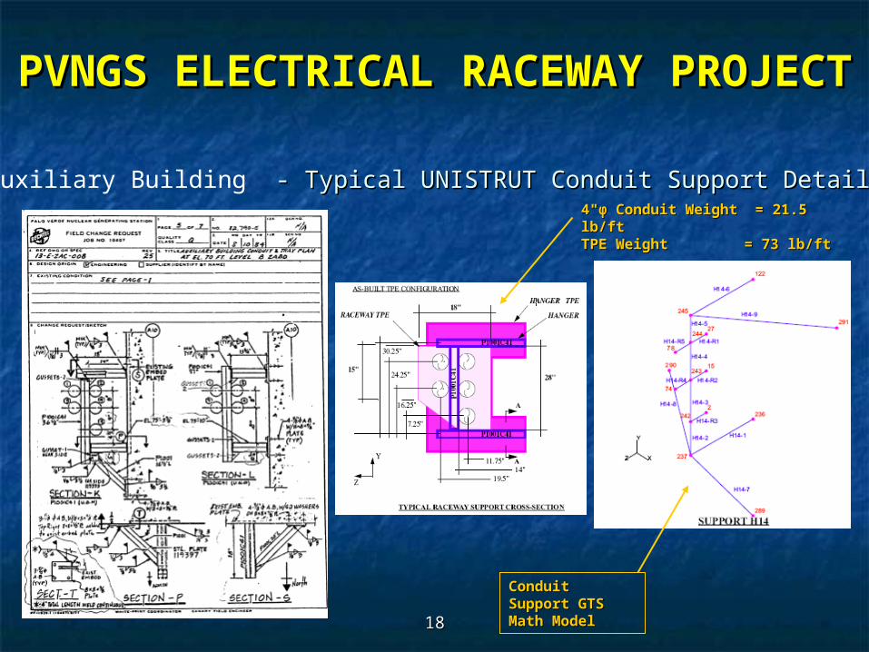
PVNGS ELECTRICAL RACEWAY PVNGS ELECTRICAL RACEWAY PROJECTPROJECT
70' Auxiliary Building - Typical UNISTRUT Conduit Support Details - Typical UNISTRUT Conduit Support Details4"φ Conduit Weight 4"φ Conduit Weight = 21.5 = 21.5 lb/ftlb/ftTPE Weight TPE Weight = 73 lb/ft= 73 lb/ft
Conduit Conduit Support GTS Support GTS Math ModelMath Model

1919
PVNGS ELECTRICAL RACEWAY PVNGS ELECTRICAL RACEWAY PROJECTPROJECT
70' Auxiliary Building – Conduit System
Conduit Conduit SystemSystem
GTS Math GTS Math ModelModel
2020
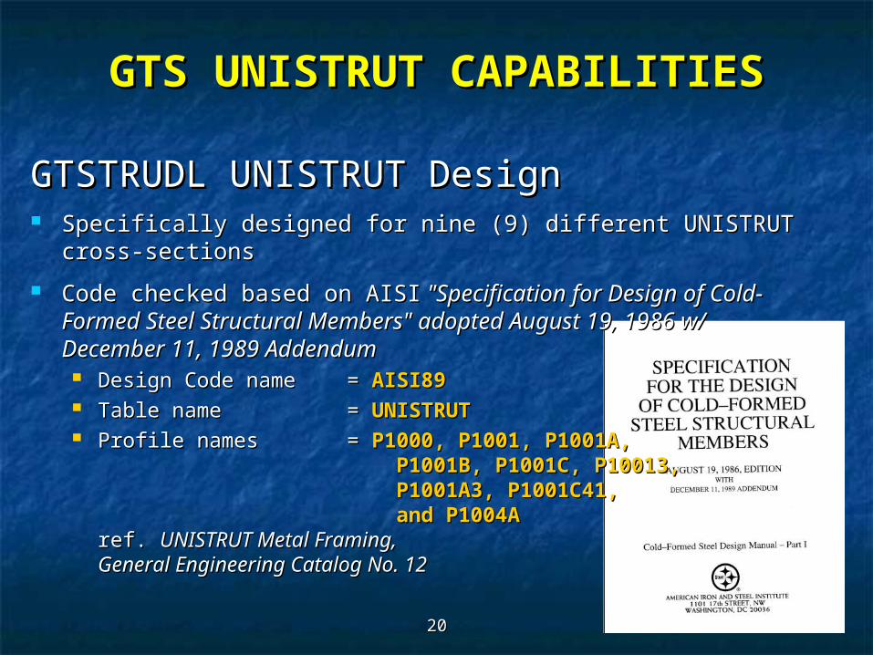
GTS UNISTRUT CAPABILITIESGTS UNISTRUT CAPABILITIES
GTSTRUDL UNISTRUT DesignGTSTRUDL UNISTRUT Design Specifically designed for nine (9) different UNISTRUT cross-Specifically designed for nine (9) different UNISTRUT cross-
sectionssections
Code checked based on AISICode checked based on AISI "Specification for Design of Cold- "Specification for Design of Cold- Formed Steel Structural Members" adopted August 19, 1986 Formed Steel Structural Members" adopted August 19, 1986 w/ December 11, 1989 Addendumw/ December 11, 1989 Addendum Design Code name Design Code name = = AISI89AISI89 Table name Table name = = UNISTRUTUNISTRUT Profile names Profile names = = P1000, P1001, P1001A, P1000, P1001, P1001A,
P1001B, P1001C, P10013, P1001B, P1001C, P10013, P1001A3, P1001C41, P1001A3, P1001C41, and P1004A and P1004A
ref. ref. UNISTRUT Metal Framing, UNISTRUT Metal Framing, General Engineering Catalog No. 12General Engineering Catalog No. 12
2121
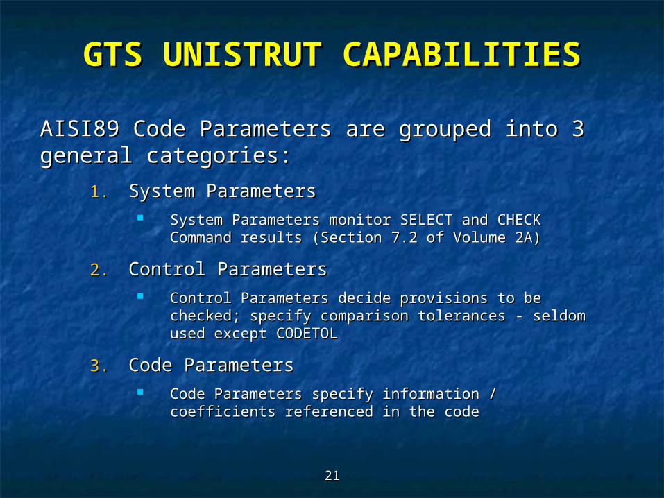
AISI89 Code Parameters are grouped into 3 AISI89 Code Parameters are grouped into 3 general categories:general categories:
1.1. System ParametersSystem Parameters System Parameters monitor SELECT and CHECK Command System Parameters monitor SELECT and CHECK Command
results (Section 7.2 of Volume 2A)results (Section 7.2 of Volume 2A)
2.2. Control ParametersControl Parameters Control Parameters decide provisions to be checked; Control Parameters decide provisions to be checked;
specify comparison tolerances - seldom used except specify comparison tolerances - seldom used except CODETOLCODETOL
3.3. Code Parameters Code Parameters Code Parameters specify information / coefficients Code Parameters specify information / coefficients
referenced in the code referenced in the code
GTS UNISTRUT CAPABILITIESGTS UNISTRUT CAPABILITIES
2222
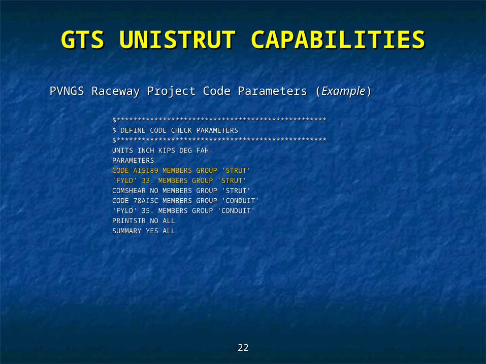
PVNGS Raceway Project Code Parameters (PVNGS Raceway Project Code Parameters (ExampleExample))
$**************************************************$**************************************************
$ DEFINE CODE CHECK PARAMETERS$ DEFINE CODE CHECK PARAMETERS
$**************************************************$**************************************************
UNITS INCH KIPS DEG FAHUNITS INCH KIPS DEG FAH
PARAMETERSPARAMETERS
CODE AISI89 MEMBERS GROUP 'STRUT'CODE AISI89 MEMBERS GROUP 'STRUT'
'FYLD' 33. MEMBERS GROUP 'STRUT''FYLD' 33. MEMBERS GROUP 'STRUT'
COMSHEAR NO MEMBERS GROUP 'STRUT'COMSHEAR NO MEMBERS GROUP 'STRUT'
CODE 78AISC MEMBERS GROUP 'CONDUIT'CODE 78AISC MEMBERS GROUP 'CONDUIT'
'FYLD' 35. MEMBERS GROUP 'CONDUIT''FYLD' 35. MEMBERS GROUP 'CONDUIT'
PRINTSTR NO ALLPRINTSTR NO ALL
SUMMARY YES ALLSUMMARY YES ALL
GTS UNISTRUT CAPABILITIESGTS UNISTRUT CAPABILITIES

2323
GTS UNISTRUT CAPABILITIESGTS UNISTRUT CAPABILITIESSystem Parameters – System Parameters – CHECK MEMBERSCHECK MEMBERS Results Results
CODE CHECK command CODE CHECK command executes code executes code provision checks provision checks and and
Returns top 2 highest Returns top 2 highest ACTUAL/LIMITING ACTUAL/LIMITING valuesvalues

2424
GTS UNISTRUT CAPABILITIESGTS UNISTRUT CAPABILITIESTroubleshoot “failed” Troubleshoot “failed” members using the members using the SUMMARIZE CODE CHECK SUMMARIZE CODE CHECK command to print computed command to print computed code provision valuescode provision values

2525
UNISTRUT Connection Analysis and Design Feature MEMBER RELEASE command of Section 2.1.8.2 of Volume 1
modified to include a TYPE option for elastic connection specifications developed for APS connection types
GTS UNISTRUT CAPABILITIESGTS UNISTRUT CAPABILITIES
{ 609} > { 609} > MEMBER RELEASESMEMBER RELEASES { 610} > $***********************************{ 610} > $*********************************** { 611} > $ UNISTRUT CONNECTIONS HANGER-5{ 611} > $ UNISTRUT CONNECTIONS HANGER-5 { 612} > $***********************************{ 612} > $*********************************** { 613} > { 613} > 'H5-1' -'H5-1' - { 614} >_{ 614} >_START ELASTIC CONN TYPE 38 -START ELASTIC CONN TYPE 38 - { 615} >_{ 615} >_END ELASTIC CONN TYPE 51END ELASTIC CONN TYPE 51 { 616} > { 616} > { 617} > 'H5-6' -{ 617} > 'H5-6' - { 618} >_START ELASTIC CONN TYPE 38 -{ 618} >_START ELASTIC CONN TYPE 38 - { 619} >_END ELASTIC CONN TYPE 48{ 619} >_END ELASTIC CONN TYPE 48 { 620} > { 620} > { 621} > 'H5-7' -{ 621} > 'H5-7' - { 622} >_START ELASTIC CONN TYPE 50 -{ 622} >_START ELASTIC CONN TYPE 50 - { 623} >_END ELASTIC CONN TYPE 11{ 623} >_END ELASTIC CONN TYPE 11
{ 1481} > $ *****************************{ 1481} > $ *****************************{ 1482} > $ * ZA 140-FT SPECTRA CONNECTION CHECK { 1482} > $ * ZA 140-FT SPECTRA CONNECTION CHECK
COMMAND FOLLOWS *COMMAND FOLLOWS * { 1483} > $ ********************************{ 1483} > $ ******************************** { 1486} > { 1486} > CHECK CONNECTION CAPACITY MEMBERS -CHECK CONNECTION CAPACITY MEMBERS - { 1487} >_{ 1487} >_'H5-1' 'H5-6' 'H5-7''H5-1' 'H5-6' 'H5-7'
CHECK COMMAND NEEDS TO SPECIFY ALL MEMBERS IDENTIFIED IN RELEASE COMMAND
0.00E0 IS REPORTED FOR MEMBER ENDS WITH NO IDENTIFIED CAPACITY
2626
Elastic Connection option in the MEMBER RELEASE Elastic Connection option in the MEMBER RELEASE command provides an elastic spring restraint between one command provides an elastic spring restraint between one or both ends of the member and the incident jointsor both ends of the member and the incident joints
‘‘elastic.con’ file installed in GTSTRUDL installation directory elastic.con’ file installed in GTSTRUDL installation directory ASCII file contains elastic connection types, connection ASCII file contains elastic connection types, connection
force/moment capacities, Translational / rotational elastic force/moment capacities, Translational / rotational elastic connections at the ends of the membersconnections at the ends of the members
Free format data to be specifiedFree format data to be specified Number of elastic connection types stored in fileNumber of elastic connection types stored in file Connection Type ID; Capacities = FX, FY, FZ, MX, MY, and MZ; Connection Type ID; Capacities = FX, FY, FZ, MX, MY, and MZ;
followed by Spring Values = KFX, KFY, KFZ, KMX, KMY, and KMZfollowed by Spring Values = KFX, KFY, KFZ, KMX, KMY, and KMZ Directions X, Y, and Z = local coordinate system of the memberDirections X, Y, and Z = local coordinate system of the member
Capacities/elastic connection springs in GTSTRUDL default Capacities/elastic connection springs in GTSTRUDL default units (inches, pounds, and radians)units (inches, pounds, and radians)
Fixed DOF= 999999 valueFixed DOF= 999999 value
GTS UNISTRUT CAPABILITIESGTS UNISTRUT CAPABILITIES
2727
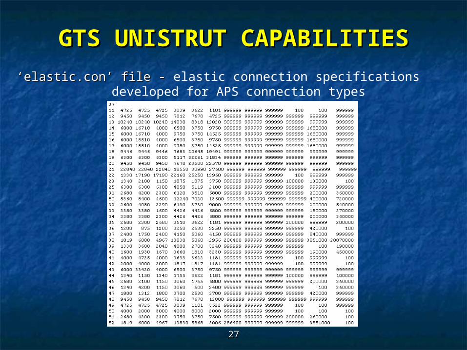
‘‘elastic.con’ file - elastic.con’ file - elastic connection specifications developed for APS connection types
GTS UNISTRUT CAPABILITIESGTS UNISTRUT CAPABILITIES
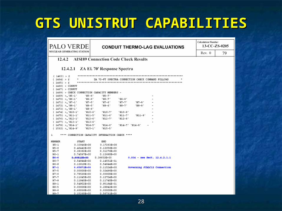
2828
GTS UNISTRUT CAPABILITIESGTS UNISTRUT CAPABILITIES

2929
GTS UNISTRUT Feature BenefitsGTS UNISTRUT Feature Benefits Code Checking Capabilities greatly expedited post-processingCode Checking Capabilities greatly expedited post-processing
results - results - PVNGS Conduit Systems were determined to meet Seismic PVNGS Conduit Systems were determined to meet Seismic Category 1 requirementsCategory 1 requirements
UNISTRUT code check is available to all users; Documentation UNISTRUT code check is available to all users; Documentation available upon requestavailable upon request
Code Check based on AISI 1986 Edition (w/ 1989 Addendum) Code Check based on AISI 1986 Edition (w/ 1989 Addendum) Load Capacity Determination procedures - cold formed steel Load Capacity Determination procedures - cold formed steel equations are force-based; not stress-based equations equations are force-based; not stress-based equations (similar to AISC LRFD concept)(similar to AISC LRFD concept)
GTS UNISTRUT CAPABILITIESGTS UNISTRUT CAPABILITIES
3030
Provide REDRAW SOLID capabilities – Beta angles for non-symmetrical shapes are difficult to verify without REDRAW SOLID
GTS UNISTRUT REQUESTSGTS UNISTRUT REQUESTS
3131
QUESTIONS ?QUESTIONS ?