Embed Size (px)
Citation preview

1
Alexander-Sadiku Alexander-Sadiku Fundamentals of Electric Fundamentals of Electric
CircuitsCircuits
Chapter 14Chapter 14
Frequency ResponseFrequency Response
Copyright © The McGraw-Hill Companies, Inc. Permission required for reproduction or display.

2
Frequency ResponseFrequency ResponseChapter 14Chapter 14
14.1 Introduction14.2 Transfer Function14.3 Series Resonance14.4 Parallel Resonance14.5 Passive Filters

3
What is FrequencyResponse of a Circuit?What is FrequencyResponse of a Circuit?
It is the variation in a circuit’s
behavior with change in signal
frequency and may also be
considered as the variation of the gain
and phase with frequency.
14.1 Introduction (1)14.1 Introduction (1)

4
14.2 Transfer Function (1)14.2 Transfer Function (1)• The transfer function H(ω) of a circuit is the
frequency-dependent ratio of a phasor output Y(ω) (an element voltage or current ) to a phasor input X(ω) (source voltage or current).
|)(H|
)(X
)(Y )(H

5
14.2 Transfer Function (2)14.2 Transfer Function (2)
• Four possible transfer functions:
)(V
)(V gain Voltage )(H
i
o
)(I
)(I gain Current )(H
i
o
)(I
)(V ImpedanceTransfer )(H
i
o
)(V
)(I AdmittanceTransfer )(H
i
o
|)(H|
)(X
)(Y )(H

6
14.2 Transfer Function (3)14.2 Transfer Function (3)Example 1
For the RC circuit shown below, obtain the transfer function Vo/Vs and its frequency response.Let vs = Vmcosωt.

7
14.2 Transfer Function (4)14.2 Transfer Function (4)
Solution:
The transfer function is
,
The magnitude is 2)/(1
1)(H
o
The phase iso
1tan
1/RCo
RC j1
1
C j1/ RCj
1
V
V)(H
s
o
Low Pass FilterLow Pass Filter

8
14.2 Transfer Function (5)14.2 Transfer Function (5)Example 2
Obtain the transfer function Vo/Vs of the RL circuit shown below, assuming vs = Vmcosωt. Sketch its frequency response.

9
14.2 Transfer Function (6)14.2 Transfer Function (6)
Solution:
The transfer function is
,
The magnitude is 2)(1
1)(H
o
The phase iso
1tan90
R/Lo
L jR
1
1
L jR
Lj
V
V)(H
s
o
High Pass FilterHigh Pass Filter

10
14.3 Series Resonance (1)14.3 Series Resonance (1)
Resonance is a condition in an RLC circuit in which the capacitive and inductive reactance are equal in magnitude, thereby resulting in purely resistive impedance.
)C
1L ( jRZ
Resonance frequency:
HzLC2
1f
rad/sLC
1
o
oro

11
14.3 Series Resonance (2)14.3 Series Resonance (2)
The features of series resonance:
The impedance is purely resistive, Z = R;• The supply voltage Vs and the current I are in phase, so
cos = 1;• The magnitude of the transfer function H(ω) = Z(ω) is
minimum;• The inductor voltage and capacitor voltage can be much
more than the source voltage.
)C
1L ( jRZ

12
14.3 Series Resonance (3)14.3 Series Resonance (3)
Bandwidth B
The frequency response of the resonance circuit current is )
C
1L ( jRZ
22
m
)C /1L (R
V|I|I
The average power absorbed by the RLC circuit is
RI2
1)(P 2
The highest power dissipated The highest power dissipated occurs at resonance:occurs at resonance: R
V
2
1)(P
2mo

13
14 3 Series Resonance (4)14 3 Series Resonance (4)
Half-power frequencies ω1 and ω2 are frequencies at which the dissipated power is half the maximum value:
The half-power frequencies can be obtained by setting Z
equal to √2 R.
4R
V
R
)2/(V
2
1)(P)(P
2m
2m
21
LC
1)
2L
R(
2L
R 21
LC
1)
2L
R(
2L
R 22 21 o
Bandwidth BBandwidth B12 B

14
14.3 Series Resonance (5)14.3 Series Resonance (5)
Quality factor, CR
1
R
L
resonanceat period onein
circuit by the dissipatedEnergy
circuit in the storedenergy Peak Q
o
o
• The quality factor is the ratio of its resonant frequency to its bandwidth.
• If the bandwidth is narrow, the quality factor of the resonant circuit must be high.
• If the band of frequencies is wide, the quality factor must be low.
The relationship between the B, Q and ωo:
CRQL
RB 2
oo

15
14.3 Series Resonance (6)14.3 Series Resonance (6)
Example 3
A series-connected circuit has R = 4 Ω and L = 25 mH.
a. Calculate the value of C that will produce a quality factor of 50.
b. Find ω1 and ω2, and B.
c. Determine the average power dissipated at ω
= ωo, ω1, ω2. Take Vm= 100V.
16
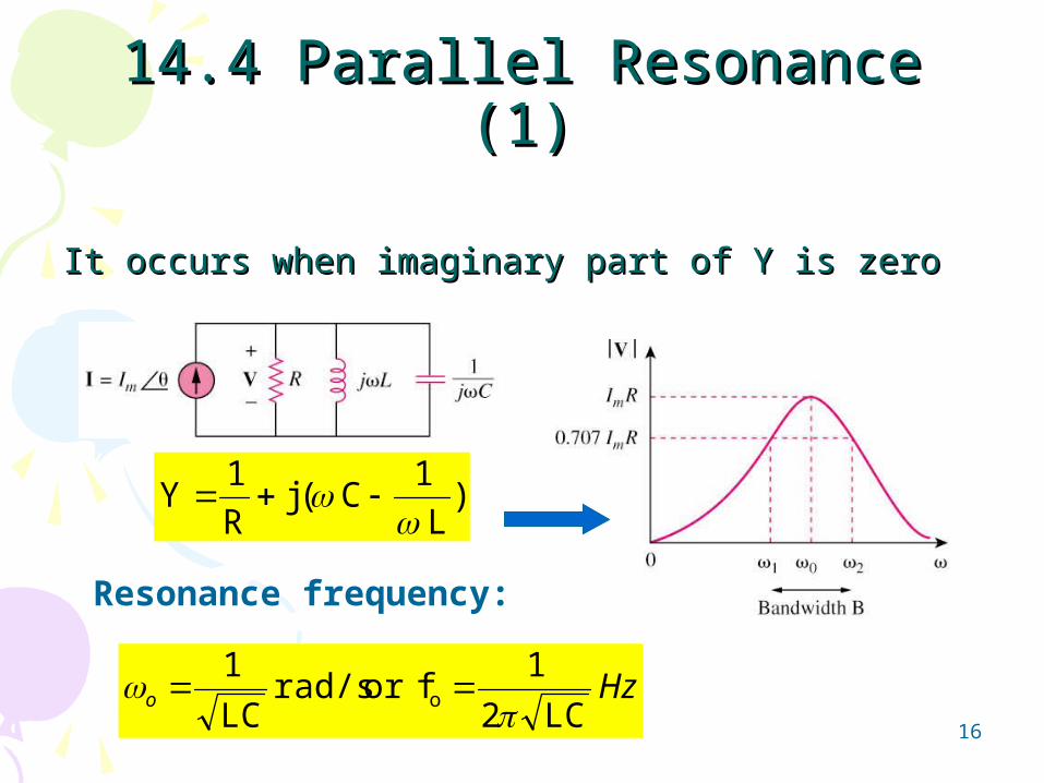
14.4 Parallel Resonance (1)14.4 Parallel Resonance (1)
Resonance frequency:
HzoLC2
1for rad/s
LC
1o
)L
1C ( j
R
1Y
It occurs when imaginary part of Y is zeroIt occurs when imaginary part of Y is zero

17
Summary of series and parallel resonance circuits:Summary of series and parallel resonance circuits:
14.4 Parallel Resonance (2)14.4 Parallel Resonance (2)
LC
1
LC
1
RC
1or
R
L
o
o
ω
ωRCor
L
Ro
o
Qo
Qo
2Q )
2Q
1( 1 2 o
o
2Q
)2Q
1( 1 2 o
o
2
Bo
2
Bo
characteristic Series circuit Parallel circuit
ωo
Q
B
ω1, ω2
Q ≥ 10, ω1, ω2

18
14.4 Parallel Resonance (3)14.4 Parallel Resonance (3)Example 4
Calculate the resonant frequency of the circuit in the figure shown below.
rad/s2.1792
19AnswerAnswer::

19
14.5 Passive Filters (1)14.5 Passive Filters (1)• A filter is a circuit that
is designed to pass signals with desired frequencies and reject or attenuate others.
• Passive filter consists of only passive element R, L and C.
• There are four types of filters.
Low Pass
High Pass
Band Pass
Band Stop

20
14.5 Passive Filters (2)14.5 Passive Filters (2)
Example 5
For the circuit in the figure below, obtain the transfer function For the circuit in the figure below, obtain the transfer function
Vo(ω)/Vi(ω). Identify the type of filter the circuit represents Vo(ω)/Vi(ω). Identify the type of filter the circuit represents
and determine the corner frequency. Take R1=100and determine the corner frequency. Take R1=100=R2 =R2
and L =2mH.and L =2mH.
krad/s25AnswerAnswer::