Embed Size (px)
Citation preview
1
Akhyari NasirTATiUC
LAN DESIGN
2
LAN Design Goals
Critical to design is insuring a fast and stable network that will scale well as the organization grows
Design steps are...1. Gather & establish design goals based on
user requirements2. Determine data traffic patterns now & in the
future3. Define Layer 1, 2, & 3 devices & the LAN/WAN
topologies4. Document physical & logical network
implementation
3
Establish the Design Goals
Although organizations are unique to the customer, the following requirements tend to be generic to all. The network must have... Functionality--speed and reliability Scalability--ability to grow without major
changes Adaptability--easily implements new
technologies Manageability--facilitates monitoring and
ease of management
4
Critical Components of LAN Design With the emergence of high-speed
technologies and complex LAN technologies, the following critical components need addressing in design Function & placement of Servers Collision Detection Microsegmentation Bandwidth v. Broadcast domains
5
Placement of Servers
Servers now perform special functions and can be categorized as either... Enterprise Servers--supports all users on
the network • DNS and mail servers• should be placed in the MDF
or... Workgroup Servers--supports a specific
set of users• file serving such as specialized databases• should be place in the IDF closest to users
6
Intranets & Collisions
This has caused an increase in needed bandwidth. Therefore, design must address...
• Type of data to be accessed• Server privileges• Outfitting desktops with faster connectivity
– More processing power– 10/100Mbps NICs to provide migration to switched
technologies Collision detection and minimization has become a
major concern as users attempt to access the same server.
As we’ve seen, switches can provide dedicated bandwidth to minimize or eliminate collisions.
7
Broadcasts & Segmentation
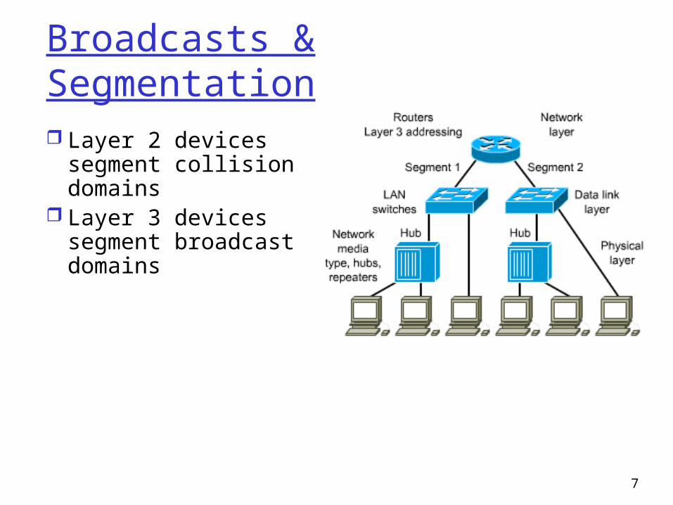
Layer 2 devices segment collision domains
Layer 3 devices segment broadcast domains
8
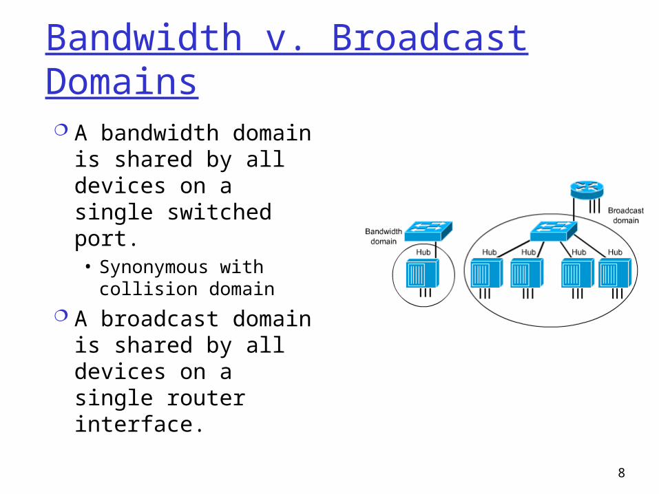
Bandwidth v. Broadcast Domains A bandwidth domain
is shared by all devices on a single switched port.• Synonymous with
collision domain A broadcast domain is
shared by all devices on a single router interface.
9
LAN Design Methodology
10
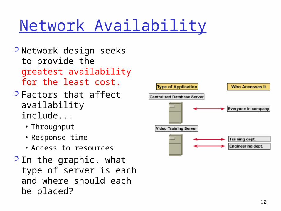
Network Availability Network design seeks to
provide the greatest availability for the least cost.
Factors that affect availability include...• Throughput• Response time• Access to resources
In the graphic, what type of server is each and where should each be placed?

11
Physical Topologies

12
Layer 1 Design
13
Ethernet Cable Runs The physical cabling (also called the cable plant) is
the most important Layer 1 issue to consider when designing a network.
Design issues include...• Type of cable to use (twisted-pair, coax, fiber)• Where to use each type (e.g. fiber on the backbone)• How far each run must travel before being terminated
(twisted-pair is limited to what distance?) In an existing LAN, a cable audit is performed to
determine where upgrading and/or replacement of bad cables is needed.
14
MDF and IDF
Short for main distribution frame, a cable rack that interconnects and manages the telecommunications wiring between itself and any number of IDFs (Intermediate Distribution Frames). Unlike an IDF, which connects internal lines to the MDF, the MDF connects private or public lines coming into a building with the internal network. For example, an enterprise that encompasses a building with several floors may have one centralized MDF on the first floor and one IDF on each of the floors that is connected to the MDF.
15
MDF & Other Acronyms
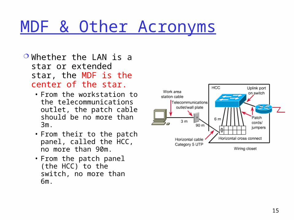
Whether the LAN is a star or extended star, the MDF is the center of the star.• From the workstation
to the telecommunications outlet, the patch cable should be no more than 3m.
• From their to the patch panel, called the HCC, no more than 90m.
• From the patch panel (the HCC) to the switch, no more than 6m.
16
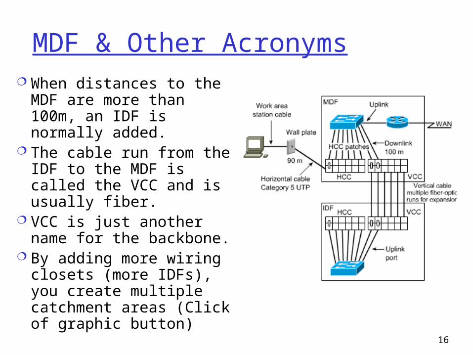
MDF & Other Acronyms When distances to the
MDF are more than 100m, an IDF is normally added.
The cable run from the IDF to the MDF is called the VCC and is usually fiber.
VCC is just another name for the backbone.
By adding more wiring closets (more IDFs), you create multiple catchment areas (Click of graphic button)
17
10BaseT and 100BaseT Ethernet
100 BaseT (also called Fast Ethernet) is now the standard for connecting IDFs to the MDF. Although you can run Fast Ethernet over
100BaseT cabling (twisted pair), the distance limitation means fiber is most often used
The 100BaseT standard running on twisted pair is called 100BaseTX
18
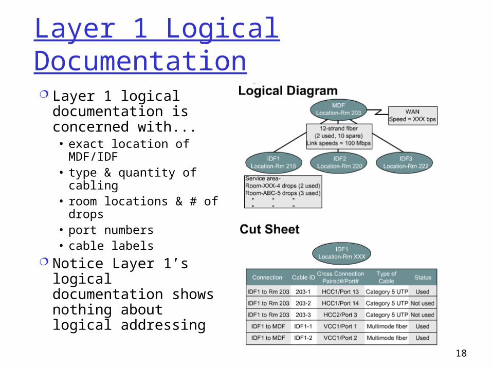
Layer 1 Logical Documentation Layer 1 logical
documentation is concerned with...• exact location of
MDF/IDF• type & quantity of
cabling• room locations & # of
drops• port numbers• cable labels
Notice Layer 1’s logical documentation shows nothing about logical addressing
19
Layer 2 Design
20
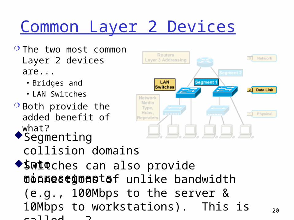
Common Layer 2 Devices The two most common
Layer 2 devices are...• Bridges and• LAN Switches
Both provide the added benefit of what?
Segmenting collision domains into microsegments.
Switches can also provide connections of unlike bandwidth (e.g., 100Mbps to the server & 10Mbps to workstations). This is called...?
21
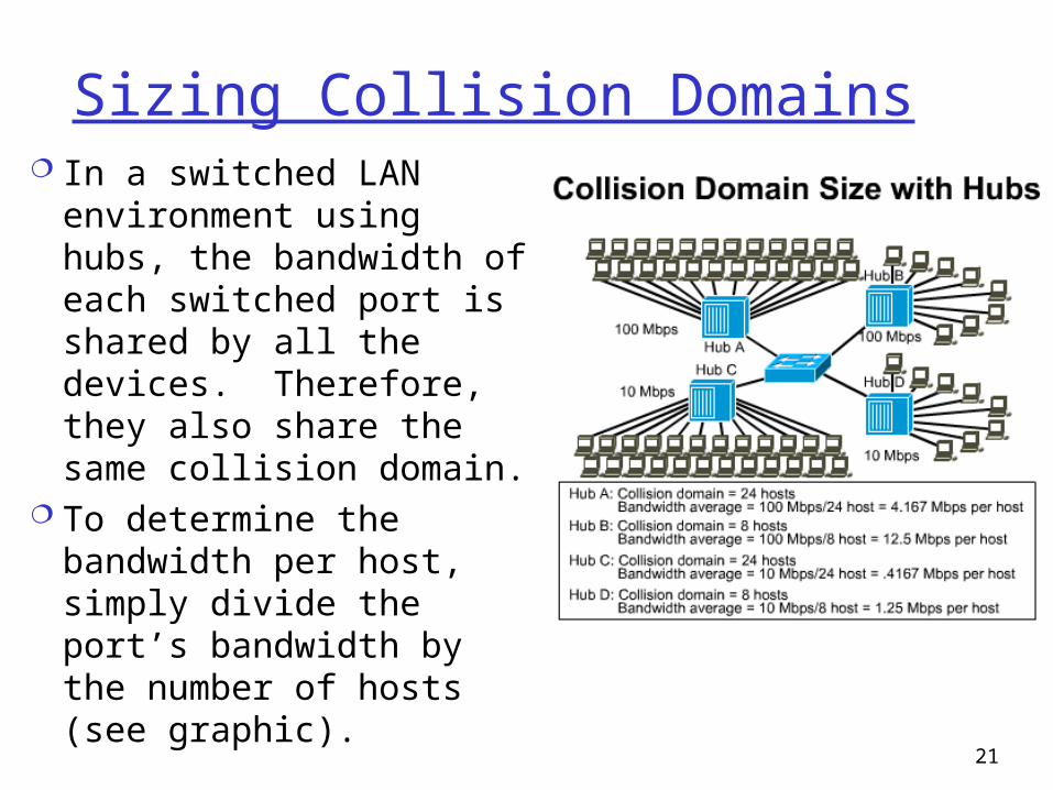
Sizing Collision Domains In a switched LAN
environment using hubs, the bandwidth of each switched port is shared by all the devices. Therefore, they also share the same collision domain.
To determine the bandwidth per host, simply divide the port’s bandwidth by the number of hosts (see graphic).
22
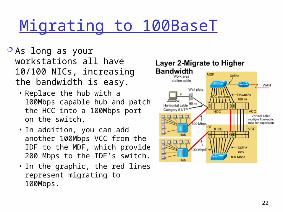
Migrating to 100BaseT As long as your
workstations all have 10/100 NICs, increasing the bandwidth is easy.• Replace the hub with a
100Mbps capable hub and patch the HCC into a 100Mbps port on the switch.
• In addition, you can add another 100Mbps VCC from the IDF to the MDF, which provide 200 Mbps to the IDF’s switch.
• In the graphic, the red lines represent migrating to 100Mbps.
23
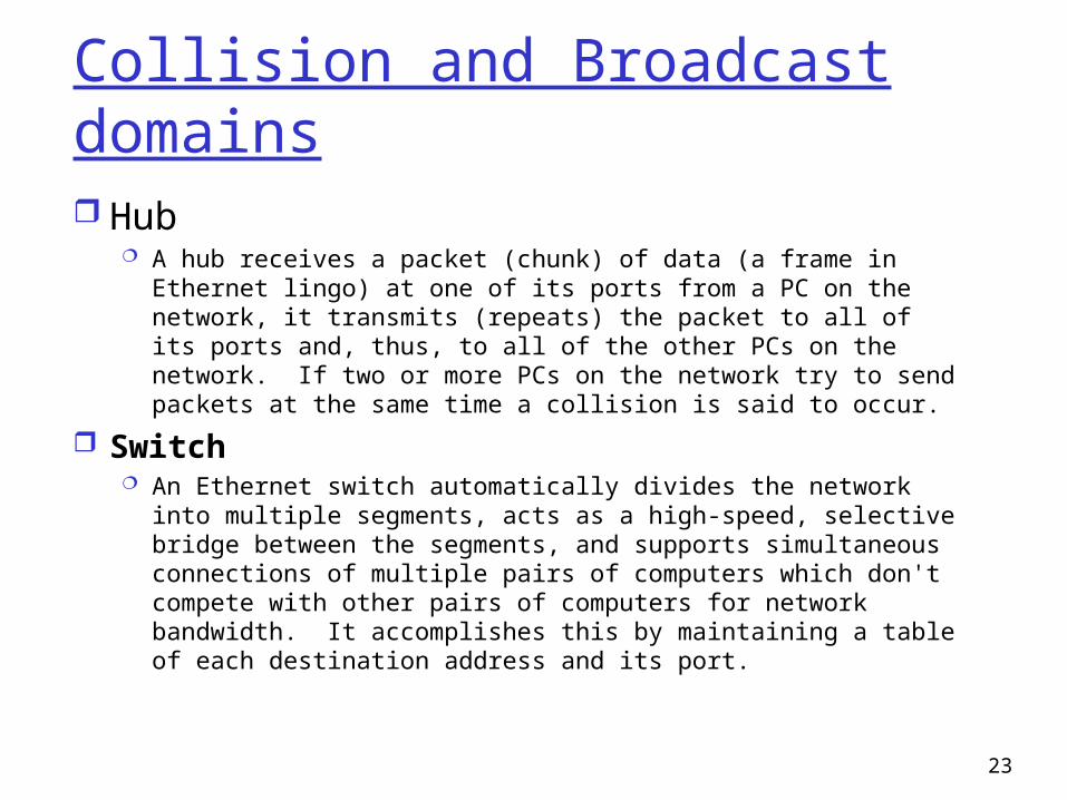
Collision and Broadcast domains Hub
A hub receives a packet (chunk) of data (a frame in Ethernet lingo) at one of its ports from a PC on the network, it transmits (repeats) the packet to all of its ports and, thus, to all of the other PCs on the network. If two or more PCs on the network try to send packets at the same time a collision is said to occur.
Switch An Ethernet switch automatically divides the network into
multiple segments, acts as a high-speed, selective bridge between the segments, and supports simultaneous connections of multiple pairs of computers which don't compete with other pairs of computers for network bandwidth. It accomplishes this by maintaining a table of each destination address and its port.

24
Layer 3 Design
25
Routers and Design
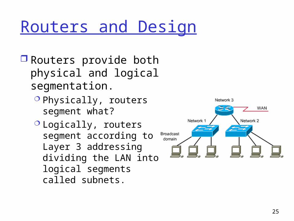
Routers provide both physical and logical segmentation. Physically, routers
segment what? Logically, routers
segment according to Layer 3 addressing dividing the LAN into logical segments called subnets.
26
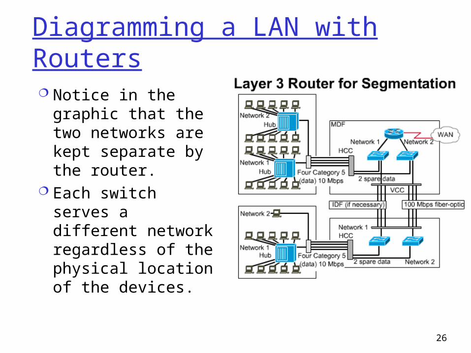
Diagramming a LAN with Routers Notice in the graphic
that the two networks are kept separate by the router.
Each switch serves a different network regardless of the physical location of the devices.
27
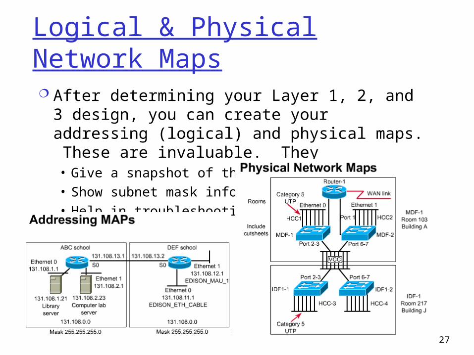
Logical & Physical Network Maps After determining your Layer 1, 2, and 3
design, you can create your addressing (logical) and physical maps. These are invaluable. They• Give a snapshot of the network• Show subnet mask info• Help in troubleshooting
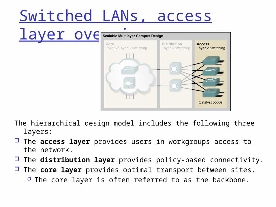
Switched LANs, access layer overview
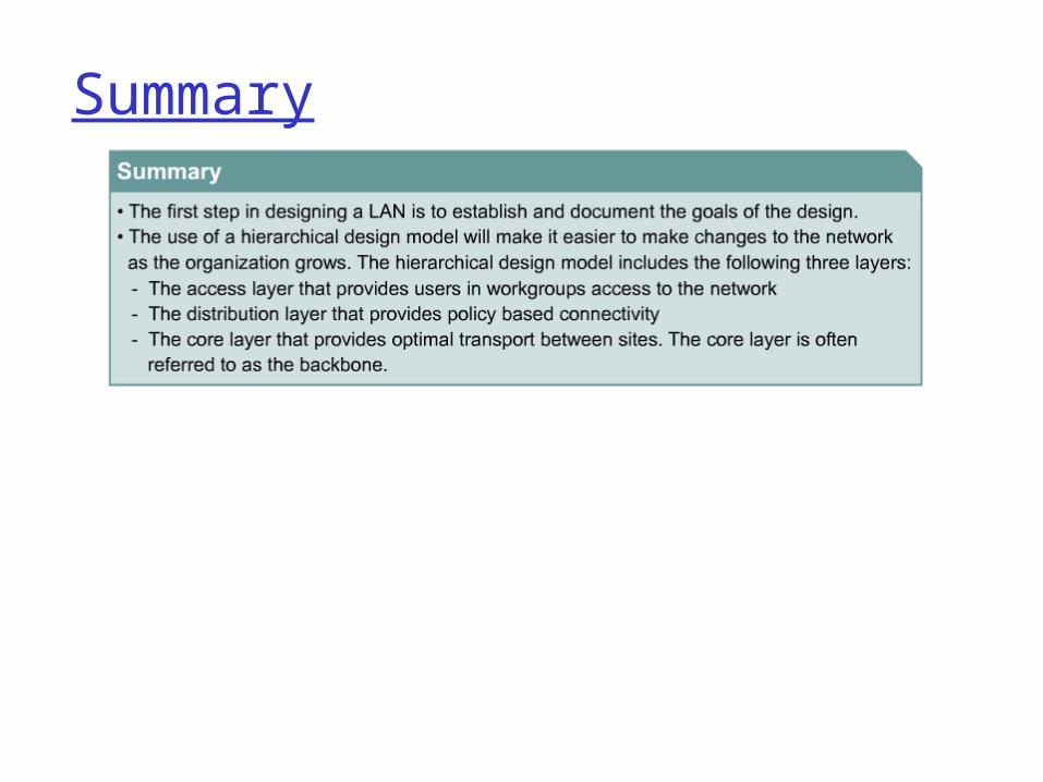
The hierarchical design model includes the following three layers:
The access layer provides users in workgroups access to the network.
The distribution layer provides policy-based connectivity. The core layer provides optimal transport between sites.
The core layer is often referred to as the backbone.
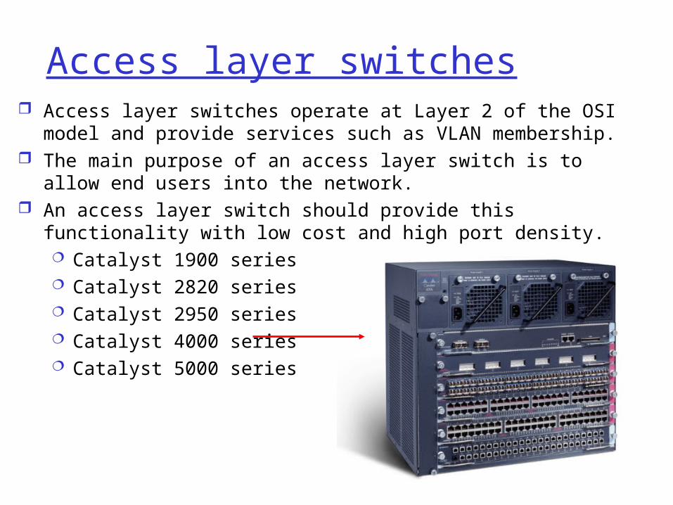
Access layer switches Access layer switches operate at Layer 2 of the OSI model and
provide services such as VLAN membership. The main purpose of an access layer switch is to allow end
users into the network. An access layer switch should provide this functionality with
low cost and high port density. Catalyst 1900 series Catalyst 2820 series Catalyst 2950 series Catalyst 4000 series Catalyst 5000 series
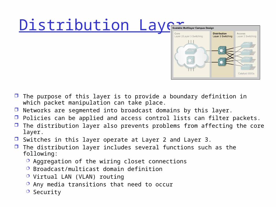
Distribution Layer
The purpose of this layer is to provide a boundary definition in which packet manipulation can take place.
Networks are segmented into broadcast domains by this layer. Policies can be applied and access control lists can filter packets. The distribution layer also prevents problems from affecting the core layer. Switches in this layer operate at Layer 2 and Layer 3. The distribution layer includes several functions such as the following:
Aggregation of the wiring closet connections Broadcast/multicast domain definition Virtual LAN (VLAN) routing Any media transitions that need to occur Security
Distribution layer switches
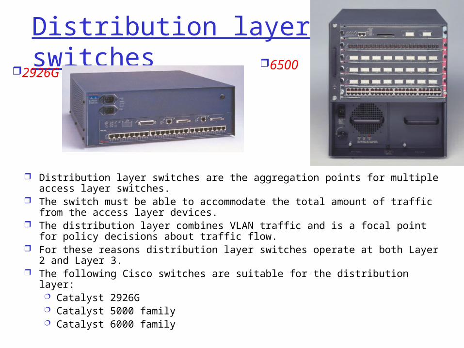
Distribution layer switches are the aggregation points for multiple access layer switches.
The switch must be able to accommodate the total amount of traffic from the access layer devices.
The distribution layer combines VLAN traffic and is a focal point for policy decisions about traffic flow.
For these reasons distribution layer switches operate at both Layer 2 and Layer 3.
The following Cisco switches are suitable for the distribution layer: Catalyst 2926G Catalyst 5000 family Catalyst 6000 family
2926G6500
Core Layer
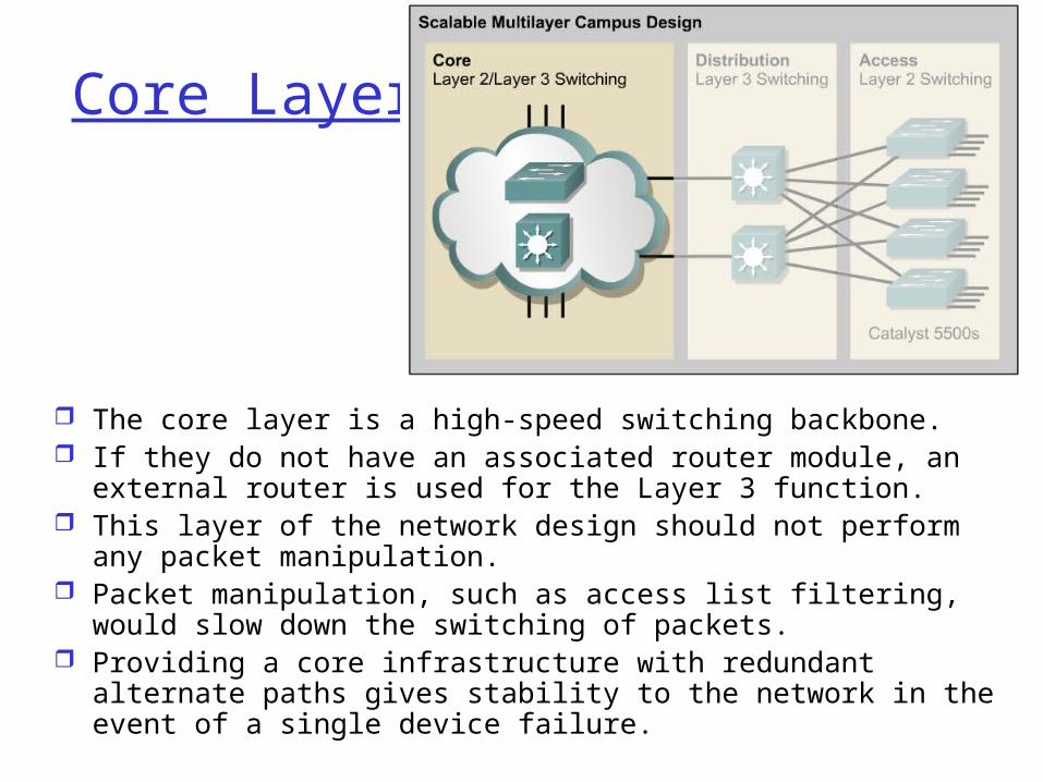
The core layer is a high-speed switching backbone. If they do not have an associated router module, an external
router is used for the Layer 3 function. This layer of the network design should not perform any
packet manipulation. Packet manipulation, such as access list filtering, would slow
down the switching of packets. Providing a core infrastructure with redundant alternate paths
gives stability to the network in the event of a single device failure.
Core Layer Switches
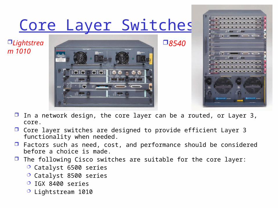
In a network design, the core layer can be a routed, or Layer 3, core. Core layer switches are designed to provide efficient Layer 3
functionality when needed. Factors such as need, cost, and performance should be considered
before a choice is made. The following Cisco switches are suitable for the core layer:
Catalyst 6500 series Catalyst 8500 series IGX 8400 series Lightstream 1010
Lightstream 1010
8540
Summary
36
References
Slides adapted from Allan Johnson, CCNA