Embed Size (px)
Citation preview

1ST AIAA ICE PREDICTION WORKSHOP
3D Droplet Impingement and 2D/3D Ice Accretion cases
AIT Austrian Institute of Technology
Alessandro Zanon
James Page
Damiano Tormen

Summary
• 3D droplet impingement
• Cases 131 and 132: axysimmetric inlet
• Focus on effects of particle size distribution
• 2D ice accretion
• Cases 241 and 242: 18-in NACA23012 aerofoil
• Focus on effects of ambient parameters and numerical settings (turbulence and roughness models)
• 3D ice accretion
• Cases 361 and 362: 30º swept NACA 0012
• Focus on effects of ice density modelling
• Conclusions
228.07.2021

3D droplet impingement
328.07.2021

Droplet impingement: Axisymmetric inlet, Mach=0.23, α=15º, MVD=20.36 μm
Workflow:
1. Mesh
• provided by the IPW organizers (tetra with prismatic inflation layers)
2. Flow field computation
• Fluent solver mimicking IPW prescribed BC setup
• 𝑘 − 𝜔 SST, production limiter, viscous heating, compressibility effects
• Secon-order accurate numerical schemes
3. Droplet Impingement computation
• FENSAP-ICE DROP3D solver
• Drag law for spheres
• Both Monodispersed and Experimental 7 bin PSD [NASA CR 4257]
Case 131
Case 132
Imposed ሶ𝑚
Case 131: Mass flow rate = 7.8 kg/s
Case 132: Mass flow rate = 10.41 kg/s
428.07.2021

Case 131: Droplet impingement: Axisymmetric inlet
Mach=0.23, α=15º, MVD=20.36 μmMass flow rate = 7.8 kg/s
528.07.2021

Case 132: Droplet impingement: Axisymmetric inlet
Mach=0.23, α=15º, MVD=20.36 μmMass flow rate = 10.41 kg/s
628.07.2021

2D ice accretion
728.07.2021
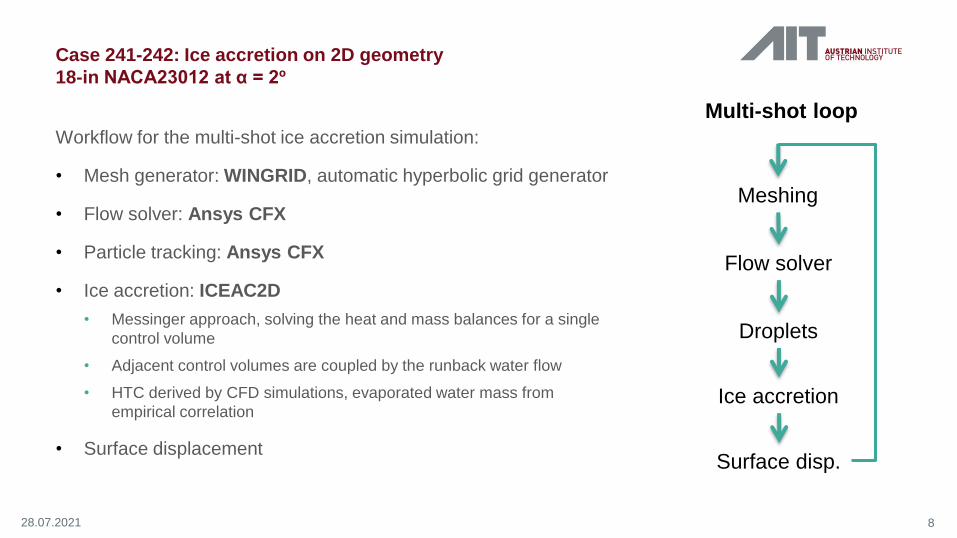
Workflow for the multi-shot ice accretion simulation:
• Mesh generator: WINGRID, automatic hyperbolic grid generator
• Flow solver: Ansys CFX
• Particle tracking: Ansys CFX
• Ice accretion: ICEAC2D
• Messinger approach, solving the heat and mass balances for a single
control volume
• Adjacent control volumes are coupled by the runback water flow
• HTC derived by CFD simulations, evaporated water mass from
empirical correlation
• Surface displacement
Case 241-242: Ice accretion on 2D geometry
18-in NACA23012 at α = 2º
Multi-shot loop
Meshing
Flow solver
Droplets
Ice accretion
Surface disp.
828.07.2021
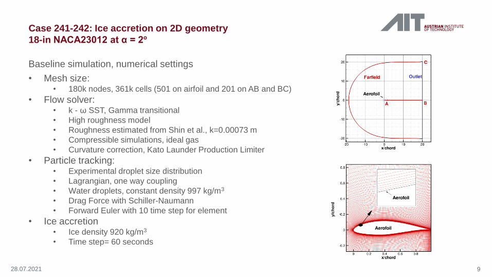
Baseline simulation, numerical settings
• Mesh size: • 180k nodes, 361k cells (501 on airfoil and 201 on AB and BC)
• Flow solver:• k - ω SST, Gamma transitional
• High roughness model
• Roughness estimated from Shin et al., k=0.00073 m
• Compressible simulations, ideal gas
• Curvature correction, Kato Launder Production Limiter
• Particle tracking: • Experimental droplet size distribution
• Lagrangian, one way coupling
• Water droplets, constant density 997 kg/m3
• Drag Force with Schiller-Naumann
• Forward Euler with 10 time step for element
• Ice accretion• Ice density 920 kg/m3
• Time step= 60 seconds
Case 241-242: Ice accretion on 2D geometry
18-in NACA23012 at α = 2º
928.07.2021
y/c
ho
rd

• Discrepancies between Computed and Experimental
Cp on the suction side are not in line with literature
• Excellent agreement of Baseline result
• Dt/2 = time step of 30s (baseline is 60s)
• Monodispersed = 30 micron
Case 241: Rime ice, Ice accretion on 2D geometry
18-in NACA23012 at α = 2º
1028.07.2021

• Baseline results, as per NASA/TM—2015-
218724
• T=265.65 K
• LWC=0.75 g/m3
• T, LWC from IPW dataset
• T=266.05 K
• LWC=0.81 g/m3
• T=264.65 K & T= 263.65 K
• Tinf = Texp - 1 K & Tinf = Texp - 2 K
To visualize impact of bulk flow temperature on
Horns position.
Case 242: Glaze ice, Ice accretion on 2D geometry
18-in NACA23012 at α = 2º
1128.07.2021

Impact of different numerical settings on HTC and on Ice shape:
• Transitional model vs Fully turbulent (Baseline result vs FT)
• Imposed surface temperature (baseline Tinf - 10K) to compute the HTC (FT vs FT, Tinf -1)
• Formulation of the wall roughness: high roughness vs Standard Roughness (FT , Tinf -1 vs FT, Tinf -1, SR)
• Value of the roughness (FT , Tinf -1, SR vs FT, Tinf -1, SR, k/10 vs FT, Tinf -1, SR, k*0)
Case 242: Glaze ice, Ice accretion on 2D geometry
18-in NACA23012 at α = 2º
1228.07.2021
Tinf
Tinf
Tinf
Tinf

3D ice accretion
1328.07.2021

• FENSAP-ICE
• Multishot sequence with 10 x 2 minute shots:
1. Fluent solver mimicking IPW prescribed setup.
2. DROP3D: no splashing, no break-up.
3. ICE3D: rime model, variable ice density,
constant roughness k=0.0005 m.
4. Fluent remeshing mimicking IPW prescribed
mesh density.
Cut at 55% span
for all other data
50 cuts from 72% to 88%
span (LE) for 20 min ice
MCCS
Post processing with in-house developed Python scripts:
Case 361: 30º swept NACA 0012, 200 kts and 257 K, MVD=34.7 μm
20 minutes rime icing
1428.07.2021

1. Aerofoil Cp: discrepancy possibly
related to mesh density and/or
short length of computational
domain.
2. HTC.
3. Aerofoil surface temperature (flat
top feature).
4. Collection efficiency
5. Ice density: peak around 700
kg/m3)
Ae
rofo
ilsu
rfa
ce
tem
pe
ratu
re(K
)
Streamwise distance from highlight (m) Streamwise distance from highlight (m)Streamwise distance from highlight (m)
Streamwise distance from highlight (m)Normalized chord, x/c
Ice
de
nsity
(kg
/m3)
Colle
ctio
n e
ffic
ien
cy
HT
C [
W/ m
2K
]
Cp
15
Case 361: 30º swept NACA 0012, 200 kts and 257 K, MVD=34.7 μm
20 minutes rime icing
28.07.2021

16
Case 362: 30º swept NACA 0012, 200 kts and 266 K, MVD=34.7 μm
20 minutes glaze icing
• FENSAP-ICE
• Multishot sequence with 10 x 2 minute shots:
1. Fluent solver mimicking IPW prescribed setup.
2. DROP3D: no splashing, no break-up.
3. ICE3D: rime model, variable ice density,
constant roughness k=0.0005 m.
4. Fluent remeshing mimicking IPW prescribed
mesh density.
Cut at 55% span
for all other data
50 cuts from 72% to 88%
span (LE) for 20 min ice
MCCS
Post processing with in-house developed Python scripts:
28.07.2021

17
Case 362: 30º swept NACA 0012, 200 kts and 266 K, MVD=34.7 μm
20 minutes glaze icing
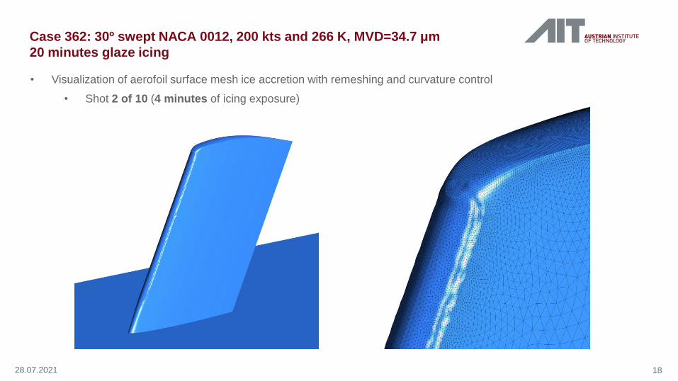
• Visualization of aerofoil surface mesh ice accretion with remeshing and curvature control
• Clean wing
28.07.2021
18
• Visualization of aerofoil surface mesh ice accretion with remeshing and curvature control
• Shot 2 of 10 (4 minutes of icing exposure)
28.07.2021
Case 362: 30º swept NACA 0012, 200 kts and 266 K, MVD=34.7 μm
20 minutes glaze icing

19
• Visualization of aerofoil surface mesh ice accretion with remeshing and curvature control
• Shot 4 of 10 (8 minutes of icing exposure)
28.07.2021
Case 362: 30º swept NACA 0012, 200 kts and 266 K, MVD=34.7 μm
20 minutes glaze icing

20
• Visualization of aerofoil surface mesh ice accretion with remeshing and curvature control
• Shot 6 of 10 (12 minutes of icing exposure)
28.07.2021
Case 362: 30º swept NACA 0012, 200 kts and 266 K, MVD=34.7 μm
20 minutes glaze icing

21
• Visualization of aerofoil surface mesh ice accretion with remeshing and curvature control
• Shot 8 of 10 (16 minutes of icing exposure)
28.07.2021
Case 362: 30º swept NACA 0012, 200 kts and 266 K, MVD=34.7 μm
20 minutes glaze icing

22
• Visualization of aerofoil surface mesh ice accretion with remeshing and curvature control
• Final ice shape: shot 10 of 10 (20 minutes of icing exposure)
28.07.2021
Case 362: 30º swept NACA 0012, 200 kts and 266 K, MVD=34.7 μm
20 minutes glaze icing

Conclusions
2328.07.2021
• 3D droplet impingement
• It is fundamental to properly account for PSD to obtain reliable impingment predictions
• Good agreement of the impingment limits obtained, but 𝛽 peaks largely overpredicted at some locations
• Mismatch between predictions and experiments probably due to inaccuracies in experimental data
• 2D ice accretion
• For rime ice, excellent agreement between predicted and experimental ice shapes
• For glaze ice, fairly good prediction of the ice shape obtained by imposing Tinf = Texp – 2 K
• The imposed ambient T and surface roughness have a large impact on the predicted ice shape (horn positions
and ice limits)
• 3D ice accretion
• For rime ice, fairly good prediction of the ice limits obtained, but maximum ice thickness largely overpredicted
• For glaze ice, fairly good prediction of the ice limits and horn lengths. Inaccuracy in horn angle prediction.
• For both rime and glaze ice conditions, a proper modelling of the ice density is fundamental to improve the
accuracy of the ice shape predictions

THANK YOU!
Questions?

![, Allen, C., & Rendall, T. (2019). Efficient Aero-Structural Wing AIAA Scitech … · In AIAA Scitech 2019 Forum [AIAA 2019-1701] (AIAA Scitech 2019 Forum). American Institute of](https://img.pdfslide.us/doc/110x75/6089b44b26d0b4646a6cbe59/-allen-c-rendall-t-2019-efficient-aero-structural-wing-aiaa-scitech.jpg)