Embed Size (px)
Citation preview
1
Abstract A set of guidelines for circuit layout to
consider is presented, as it relates to structural concepts. Namely, shock and vibration environments. The information is targeted to electrically-minded engineers that have little experience in structural analysis and test. It aids understanding the trades that accompany part placement beyond common electrical and thermal considerations.

Good Vibrations in Electronics
Structural Considerations for Electronics Systems Design
STI Electronics, Inc.Jason Tynes, Manufacturing Engineer

3
Outline Overview Why should I care? Mode Shapes Profile Comparisons How to Use this Information for
Design Test and Verification Methods

4
Overview What is Vibration?
Random Vibration – motion that cannot be precisely predicted
i.e. Vibrating seat in moving vehicle What is Shock
Physical Shock – sudden acceleration that can typically be predicted
i.e. Impacts/drops Vibration and shocks stimulate system We are typically concerned with the response – not
stimuli Response – how the system reacts to a specific stimulus Local stresses and deflections

5
Who Cares???? Why would a non-mechanical person care
about vibration anyway?
Concurrent Circuit Design Flow
Electrical Functions
Mechanical Functions
Packaging Trade Studies CAD Modeling
Board Outline
and Thickness
Functional Trade Studies
Schematic Development Part Selection Component
Layout Trace Routing Design Rule Checks
Structural and Tolerance Analysis
Thermal Analysis
Technical DataPackage
Mfg/Gerber Plots
PCB and CCA
Drawings
Power, Duty, and Location
Info
Keepout and High
Stress Areas
Detailed Drawing
Development

6
Who Cares???? Communication of Keep Out and High
Stress Areas typically occurs after board outline has been transmitted, if communicated at all Layout is typically underway and driven
by schematic requirements long before structural input is available
Structural Analysts check/verify stress margins are acceptable

7
So… Why do I Care Again? This could be your BGA
Says the Structural Analyst: The board survived. Was that your BGA???

8
Mode Shapes The shape and frequency of
the board during natural, sinusoidal movement
Recall simple harmonic motion
1 Dimensional Medium (Line) Mode shape #7 requires 49X
the energy of #1 in order to achieve similar amplitudes
Conversely, mode shape #7 exhibits 1/49th the amplitude of #1 with similar energy
Energy∝ 𝑓 2𝐴2
Consta
nt A
mplitu
de
Less Energy
Much More Energy

9
Complex Shapes with 2D Medium
1st 2nd
3rd 4th
Mode shapes generated for representative PCB Using FEA tool Standard PCB Material Properties
Amplitude/Displacement causes stress Higher Frequency Lower Amplitude Lower stresses
For Constant EnergyMost StressfulLeast Stressful

10
Shape Frequency Frequency Shape
489 Hz 2441 Hz
950 Hz 2513 Hz
1397 Hz 3774 Hz
1440 Hz 4622 Hz
2243 Hz 4841 Hz
More Complex Shapes when Constrained Mode shapes
when restrained Most relevant More complex
Usually only insightful to about 2,000 Hz
Reduce first 4 or 5 modes to most likely to cause damage

11
Shape Frequency
489 Hz
950 Hz
1397 Hz
1440 Hz
2243 Hz
Mode Shape Reduction Which Mode(s) are more likely to be excited in
the environment that hardware is to be used? Depends on the environment For Profile below, Frequencies Between 300 and
1000Hz are Energetic 489 and 950 Hz modes to be excited 489 Most susceptible due to increased amplitude

12
How to Use Info Showing 489 Hz
Mode Avoid placing large
footprint and/or massive components in high stress areas Avoid positioning
mission-critical pins within high-damage areas
Bad
Best
Better
Mission Critical Pins of Grid-Array Component
Best
Bad

13
How to Use Info Everything so far can be done at your computer
workstation Free/Cheap CAD Software Available Online (Cubify
Design Shown Here) Free/Cheap FEA Software Available Online (LISA-
Finite Element Technologies Shown Here) Testing/Verification cannot be performed on a
computer workstation Correlation between computer model/analysis
predictions and real response is critical• Supports Predictions on Design Margin• Enables Improved Model/Analysis Practices
Shaker Table and Real Hardware Required Testing Required to Instill Confidence in Design
Choices and Analysis
14
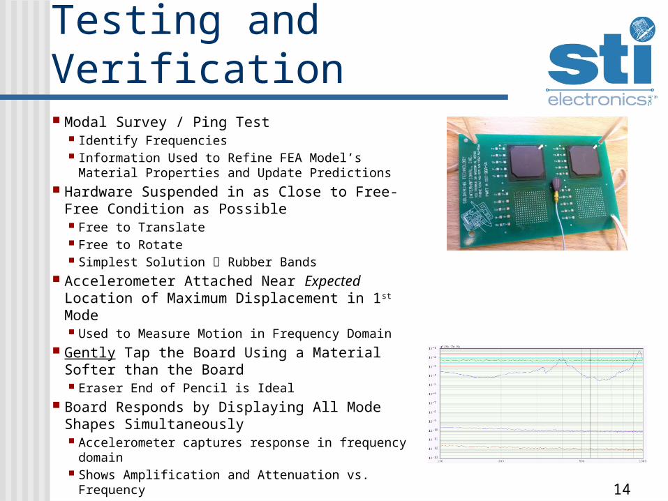
Testing and Verification Modal Survey / Ping Test
Identify Frequencies Information Used to Refine FEA Model’s Material
Properties and Update Predictions Hardware Suspended in as Close to Free-Free
Condition as Possible Free to Translate Free to Rotate Simplest Solution Rubber Bands
Accelerometer Attached Near Expected Location of Maximum Displacement in 1st Mode
Used to Measure Motion in Frequency Domain Gently Tap the Board Using a Material Softer
than the Board Eraser End of Pencil is Ideal
Board Responds by Displaying All Mode Shapes Simultaneously
Accelerometer captures response in frequency domain
Shows Amplification and Attenuation vs. Frequency
15
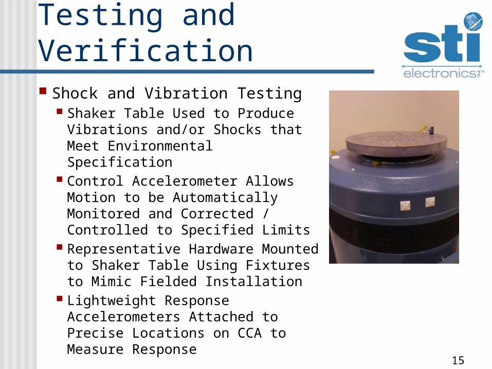
Testing and Verification Shock and Vibration Testing
Shaker Table Used to Produce Vibrations and/or Shocks that Meet Environmental Specification
Control Accelerometer Allows Motion to be Automatically Monitored and Corrected / Controlled to Specified Limits
Representative Hardware Mounted to Shaker Table Using Fixtures to Mimic Fielded Installation
Lightweight Response Accelerometers Attached to Precise Locations on CCA to Measure Response

16
Conclusion Have expectations for electronics
environmental exposure Part placement and even orientation
can be the difference between success and failure of fielded electronics
Get to know your mechanical analysts, including the structural variety
Test to make sure your assumptions are legitimate
17
Thank You Questions???
Jason Tynes (256) 705-5511
STI Electronics, Inc.261 Palmer RdMadison, AL


![SHOCK[1] - Hypovolemic Shock](https://img.pdfslide.us/doc/110x75/58edc1bc1a28abae538b4711/shock1-hypovolemic-shock.jpg)

