Embed Size (px)
Citation preview
PL-TR--95-1109 PL-TR-95-1109
QUASI-WELD-FREE BELLOWS
William RaserPaul IbanezArthur SullivanDave Clark
Anco Engineers Inc.4826 Stirling DriveBoulder, CO 80301
September 1995
Final Report
WARNING - This document contains technical data whoseD....bstribution authorized to DoD) components only, Proprietary export is restricted by the Arms Export Control Act (Title:Thbfrmation; Septem~ber 1995. Other requests for this 22, T).S.C., See 2751 Lt se.) or The Extport Administrationd0ocument shel be ted to AFMC/STI. Act of 1979, as atmended (Title 50, U.S.C,. App, 2401, qt
.... ...... sq.). Violations of these export laws arc subject to severecriminal penalties. Disseminate LAW the provisions of Dol)Directive 5230.25 and AR~ 61-204,
DESTRUCTON NOTICE, For classified dAocuments, -follow the procedures in DoD 52022-~M, Industrial Security Manual,Section 11-1 9 or Dofl 5200. 1-R, Information Security Programu Regulation. Chapter IX For unclassified, iried documents, destroy
:.,:b any method that will prevent disclosuire of contents or reconstiruction of the document,
~± PHILLIEPS LABORATORYSpace and Missiles Technology Directorate
A AIR FORCE MATERIEL COMMANDKIRTLAND AIR FORCE BASE, NM 87117-5776
1 9960215 032DTT('0TTPT ;CUDI
U IN CLA55IP ILL)
AD NUMBER
NEW LIMITATION CHANGETO DISTRIBUTION STATEMENT A -
Approved for public release; Distri-bution unlimited.
Limitation Code: 1
FROM DISTRIBUTION STATEMENT
Limitation Code:
AUTHORITY
THISP PhE Lob/S, KUiNdCLnAFI,
THIS PAGE IS UNCLASSIFIED
DISCLAIMER NOTICE
THIS DOCUMENT IS BEST
QUALITY AVAILABLE. THE COPY
FURNISHED TO DTIC CONTAINED
A SIGNIFICANT NUMBER OF
COLOR PAGES WHICH DO NOT
REPRODUCE LEGIBLY ON BLACK
AND WHITE MICROFICHE.

PL-TR-95-1 109This final report was prepared by Anco Engineers, Inc., Boulder, CO under Contract F29601-94-C-0158 Job Order, 21021002, with Phillips Laboratory, Kirtland Air Force Base, NewMexico. The Laboratory Project Officer-in-Charge was Capt Jeffrey Wiese, (VTPT).
When Government drawings, specifications, or other data are used for any purpose other thanin connection with a definitely Government-related procurement, the United StatesGovernment incurs no responsibility or any obligation whatsoever. The fact that theGovernment may have formulated or in any way supplied the said drawings, specifications, orother data, is not to be regarded by implication, or otherwise in any manner construed, aslicensing the holder, or any other person or corporation; or as conveying any rights orpermission to manufacture, use, or sell any patented invention that may in any way be relatedthereto.
This report has been authored by a contractor of the United States Government. Accordingly,the United States Government retains a nonexclusive royalty-free license to publish or repro-duce the material contained herein, or allow others to do so, for the United States Governmentpurposes.
This report contains proprietary information and shall not be either released outside thegovernment, or used, duplicated or disclosed in whole or in part for manufacture orprocurement, without the written permission of the contractor. This legend shall be marked onany reproduction hereof in whole or in part.
If your address has changed, if you wish to be removed from the mailing list, or if yourorganization no longer employs the addressee, please notify PL/VTPT, 3550 Aberdeen AveSE, Kirtland AFB, NM 87117-5776 to help maintain a current mailing list.
This report has been reviewed and is approved for publication.
JEFFREY WIESE, Capt, USAFProject Officer
FOR THE COMMANDER
DAVID KRISTENSEN, Lt Col, USAF HENRY L. PUGH, JR., Col, USAFChief, Space Power and Director of Space and Missiles TechnologyThermal Management Division
DO NOT RETURN COPIES OF THIS REPORT UNLESS CONTRACTUAL OBLIGATIONSOR NOTICE ON A SPECIFIC DOCUMENT REQUIRES THAT IT BE RETURNED.

DRAFT SF 2981. Report Date (dd-mm-yy) 2. Report Type 3. Dates covered (from... to)September 1995 Final 01194 to 9/95
4. Title & subtitle 5a. Contract or Grant #Quasi-Weld-Free Bellows F29601-94-C-0158
5b. Program Element # 62601F
6. Author(s) 5c. Project # 2102William RaserPaul Ibanez 5d. Task # 10Arthur SullivanDave Clark 5e. Work Unit # 02
7. Performing Organization Name & Address 8. Performing Organization Report #Anco Engineers, Inc.4826 Stirling DriveBoulder, CO 80301
9. Sponsoring/Monitoring Agency Name & Address 10. Monitor AcronymPhillips Laboratory3550 Aberdeen SE 11.Kirtland AFB, NM 87117-5776 Monitor Report#~PL-TR-95-1 109
12. Distribution/Availability Statem~ent Distribution authorized to DoD components only; ProprietaryInformation; September 1995. Other requests for this document shall be referred to AFMC/STI.
13. Supplementary Notes
14. Abstract This research investigated the merits of certain novel bellows designs for use in Stirling andpulse tube cryocooler compressors as an alternative to the present state of the art which uses flexurebearings. The Quasi-Weld-free (QWF) bellows incorporates the low dead volume of welded bellows and highfatigue life of formed bellows. There was also a secondary goal to investigate the merits of alternate materials.The design started with Roark-Laupa approximations to develop a preliminary baseline. The primary designeffort started by developing a curve fit from the Expansion Joint Manufactures Association (EJMA) handbook(applicable to many different applications). The final design work was accomplished using Finite ElementAnalysis (FEA). The design analysis found the following: life is very sensitive to small changes in operatingparameters, variable thickness bellows are promising, EJMA and FEA showed reasonable agreement. Nohardware was fabricated but techniques were investigated.
15. Subject Terms Cryocooler, compressor, bellows, Stirling, pulse tube
19. 20. # of 21. Responsible PersonLimitation of Pages (Name and Telephone #)
16. Report 17. Abstract 18. This Page AbstractUnclassified Unclassified Unclassified 38 Capt Jeffrey Wiese
Limited (505) 846-2686
i
PL-TR--95-1109
GOVERNMENT PURPOSE LICENSE RIGHTS(SBIR PROGRAM)
Contract Number: F29601-94-C-0158Contractor: Anco Engineers, Inc.
Boulder, CO
For a period of four (4) years after delivery and acceptance of the last deliverable item under theabove contract, this technical data shall be subject to the restrictions contained in the definition of"Limited Rights" in DFARS clause at 252.227-7013. After the four-year period, the data shall besubject to the restrictions contained in the definition of "Government Purpose License Rights" inDFARS clause at 252.227-7013. The Government assumes no liability for unauthorized use ordisclosure by others. This legend shall be included on any reproduction thereof and shall behonored only as long as the data continues to meet the definition on Government purpose licenserights.
ii
ACKNOWLEDGEMENTS
This project was carried out by William Raser and Paul Ibanez, with the assistance of Arthur
Sullivan and Dave Clark at ANCO Engineers, Inc. Several individuals provided valuable
review and advice, including William Darlington of Hydrodyne, Richard Edwards and Glen
Malone of Electroformed Nickel, Tony Chiccarine of Fluitron, Vance Stapleton of the
Stapleton Company, Bob Pan and Charles Lee of the Aerospace Corporation, and Ed Zezula
(private consultant in metallurgy). Captain Jeffrey Wiese of the USAF Phillips Laboratory
was contract coordinator.
iii

iv

Executive Summary
Cryocoolers for space applications require a 5 - 7 year life with low vibration, and high
efficiency. Stirling and pulse tube cryocoolers present two of the primary options for meeting the
present space cryocooler needs. The state of the art for these types of cryocoolers use the flexure
bearing approach to suspend an oscillating piston which generates an oscillating pressure wave.
The primary disadvantage to this approach is that it requires extremely close tolerances and
alignment to maintain a clearance seal gap. The primary objective of the research was to
investigate an option to the flexure bearing compressor through the use of "Quasi Weld Free
Bellows" (QWF). A secondary objective was to investigate the merits of alternate materials and
manufacturing techniques.
Bellows offer their own strengths and weaknesses when applied to long life cryocoolers.
Standard formed bellows offer the rounded formed convolutions necessary for long fatigue life.
However, these rounded formed convolutions inherently have a large void volume which
drastically decreases the compressor efficiency. Another option is the standard welded bellows
which have sharp convolutions known for shorter fatigue life but a low dead volume leading to
better efficiency. The QWF approach attempts to apply the best of both approaches to one
design. The proof of concept models were to bond the inside radius of formed bellows to the
outside radius of welded bellows. Thus, the formed bellows approach would be used in the area
of highest fatigue stresses and the welded bellows used in the area of lower fatigue stresses to
reduce the void volume.
The approach was broken into 6 tasks. The tasks were as follows.
Task 1: Functional Definition and Design. This task sought to define typicalapplications and design variables.
Task 2 and 3: Design Analysis and Detailed Design. These tasks called for applyingvarious analytical methods to investigate the performance of various designs and toseek optimal designs. Specifically, these tasks started with Roark-Laupaapproximations to develop a preliminary baseline. The primary design effortstarted by developing a curve fit from the Expansion Joint ManufacturersAssociation (EJMA) handbook (applicable to many different applications andpossibly the most useful knowledge gained in this program). The final design workwas accomplished using Finite Element Analysis (FEA).
V
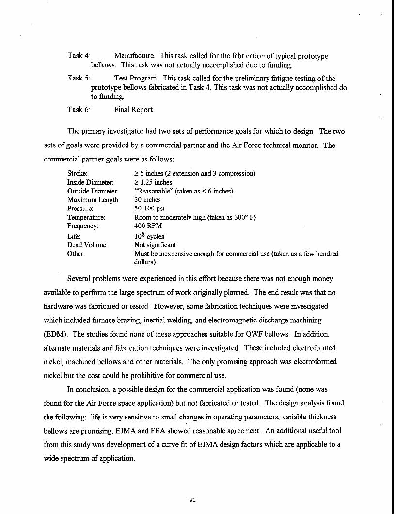
Task 4: Manufacture. This task called for the fabrication of typical prototypebellows. This task was not actually accomplished due to funding.
Task 5: Test Program. This task called for the preliminary fatigue testing of theprototype bellows fabricated in Task 4. This task was not actually accomplished doto funding.
Task 6: Final Report
The primary investigator had two sets of performance goals for which to design. The two
sets of goals were provided by a commercial partner and the Air Force technical monitor. The
commercial partner goals were as follows:
Stroke: _ 5 inches (2 extension and 3 compression)Inside Diameter: > 1.25 inchesOutside Diameter: "Reasonable" (taken as < 6 inches)Maximum Length: 30 inchesPressure: 50-100 psiTemperature: Room to moderately high (taken as 3000 F)Frequency: 400 RPMLife: 108 cyclesDead Volume: Not significantOther: Must be inexpensive enough for commercial use (taken as a few hundred
dollars)
Several problems were experienced in this effort because there was not enough money
available to perform the large spectrum of work originally planned. The end result was that no
hardware was fabricated or tested. However, some fabrication techniques were investigated
which included furnace brazing, inertial welding, and electromagnetic discharge machining
(EDM). The studies found none of these approaches suitable for QWF bellows. In addition,
alternate materials and fabrication techniques were investigated. These included electroformed
nickel, machined bellows and other materials. The only promising approach was electroformed
nickel but the cost could be prohibitive for commercial use.
In conclusion, a possible design for the commercial application was found (none was
found for the Air Force space application) but not fabricated or tested. The design analysis found
the following: life is very sensitive to small changes in operating parameters, variable thickness
bellows are promising, EJMA and FEA showed reasonable agreement. An additional useful tool
from this study was development of a curve fit of EJMA design factors which are applicable to a
wide spectrum of application.
vi

CONTENTS
Section Page
1.0 INTRODUCTION 1-1
2.0 TASK 1: FUNCTIONAL DEFINITION AND DESIGN 2-1
3.0 TASK 2 AND 3: DESIGN ANALYSIS AND DETAILED DESIGN 3-1
3.1 ANALYSIS APPROACHES 3-13.2 RESULTS OF COMPRESSOR STUDY 3-63.3 RESULTS OF CRYO-COOLER STUDY 3-73.4 A BELLOWS FIGURE OF MERIT 3-7
4.0 TASK 4: MANUFACTURE 4-1
4.1 STANDARD FABRICATION TECHNIQUES INVESTIGATED 4-14.2 ALTERNATE MATERIALS AND FABRICATION
TECHNIQUES 4-14.3 FABRICATION UNDERTAKEN 4-3
5.0 TASK 5: TEST PROGRAM 5-1
6.0 ADDITIONAL TASKS PERFORMED 6-1
6.1 NANOCRYSTALINE NICKEL 6-16.2 ORMOSIL 6-26.3 NON-CIRCULAR BELLOWS 6-26.4 ADDITIONAL COMMERCIALIZATION OPPORTUNITIES 6-2
7.0 CONCLUSIONS AND ANTICIPATED PHASE II RESEARCH ANDDEVELOPMENT 6-1
7.1 CONCLUSIONS FROM PHASE 1 7-17.2 RECOMMENDED PHASE II RESEARCH AND
DEVELOPMENT 7-1
APPENDIX
A. DISCUSSION ON BELLOWS FIGURES OF MERIT A-1
- vii

viii

1.0 INTRODUCTION
This is the final report for a six-month Phase I SBIR project (started May 1994) whose goal
was to investigate the merits of certain novel bellows designs that have the potential to
greatly extend bellows life.
Nominally, the novel design being investigated was a "Quasi Weld Free Bellows" (QWF) that
incorporated the low dead volume of a welded bellows and the high fatigue life of a formed
bellows (see Figure 1). However, there was also a secondary goal to investigate the merits of
alternate materials (nano crystalline nickel in particular) and manufacturing techniques (such
as electroforming). During the course of this project, the merits of variable cross section
bellows also became apparent. In what follows, all of these options are included in what is
referred to as the "QWF" design.
The work carried out in this project includes:
* A refined project definition. In the course of addressing the original tasks for this project(see below) it became apparent that the number of design approaches, materials,applications and application specifications, and possible areas of investigation were verylarge. It thus became necessary to modify our original plan to investigate those areas
which appeared most fruitful or to resolve unexpected issues, as is appropriate to aresearch Phase I effort.
In particular, our efforts to resolve many of the new issues which arose caused us to
curtail our efforts to fabricate a prototype bellows, and did not allow us to perform anypreliminary tests on prototypes. While this development is unfortunate, we believe that
the issues which we did investigate were necessary prior to performing any successfulfabrication and testing. These points are presented in the body of this report.
Further, while this report does present our final Phase I results, project staff continues toinvestigate further some of the issues discussed herein, as well as investigate other relatedconcepts and approaches.
* The developing of a precise definition of the specific bellows applications. Two specific
applications were defined (a commercial compressor and a cryo-cooler), so as to provide abasis for demonstration of the benefit of the design features being investigated.
1

A! B
I
Figure 1. Schematic presentation of bellows concepts.
1. Standard formed bellows. Easy to manufacture, has rounded convolutions which lead toloner fatigue life. Has limits on inner to outer radius ratio which reduce optimality ofstructural design. Has dead volume which can reduce optimal thermodynamicperformance.
2. Standard welded bellows. Can have close to zero dead volume, which leads to improvedthermodynamic performance. Can also have almost any inner to outer radius ratio, hencebe more optimal structurally. However, has sharp convolutes with weld stress zoneswhich leads to reduced fatigue life.
3. QWF fabricated design. Uses rounded formed convolutions on the inside to reduce stressconcentration and increase fatigue life. Fabrication allows almost any inner to outer radiusratio. Can have near zero dead volume because it uses sharp convolutions on the outsideand moving spacers to take up the volume on the inside (not drawn to scale). Carefulchoice of the moving spacer material and design is required to avoid contamination of theworking fluid by wear, offgassing, or chemical conversion.
4. QWF continuous variable thickness design. Using techniques such as electroforming, avariable thickness bellows can be manufactured, with thickness continuously changing tomeet optimal structural (fatigue) requirements, and using both sharp comers and movingspacers to get near zero dead volume.
2

0 The development of procedures and programs for EJMA and COSMOS FEA models ofbellows. This involved the exercising of these programs in the analysis of various bellowsand to produce optimal designs for specific applications.
* A compilation of stainless steel fatigue data at very high numbers of cycles (1 to 100million cycles).
* An investigation into the bellows manufacturing possibilities and properties ofelectroformed nano-crystalline nickel.
0 An investigation into defining a bellows figure of merit.
* Investigations of various fabrication techniques, and the consideration of a number ofalternate design approaches, applications, and materials.
Aside from Task 6 (writing of the final report) the original tasks for this project were as
follows:
Task 1: Functional Definition and Design. This task sought to define typicalapplications and design variables.
Task 2 and 3: Design Analysis and Detailed Design. These tasks called for applyingvarious analytical methods to investigate the performance of various designsand to seek optimal designs.
Task 4: Manufacture. This task called for the fabrication of typical prototypebellows.
Task 5: Test Program. This task called for the preliminary fatigue testing of theprototype bellows fabricated in Task 4.
Our achievement on each of these tasks is presented in the following sections.
3

4

5-
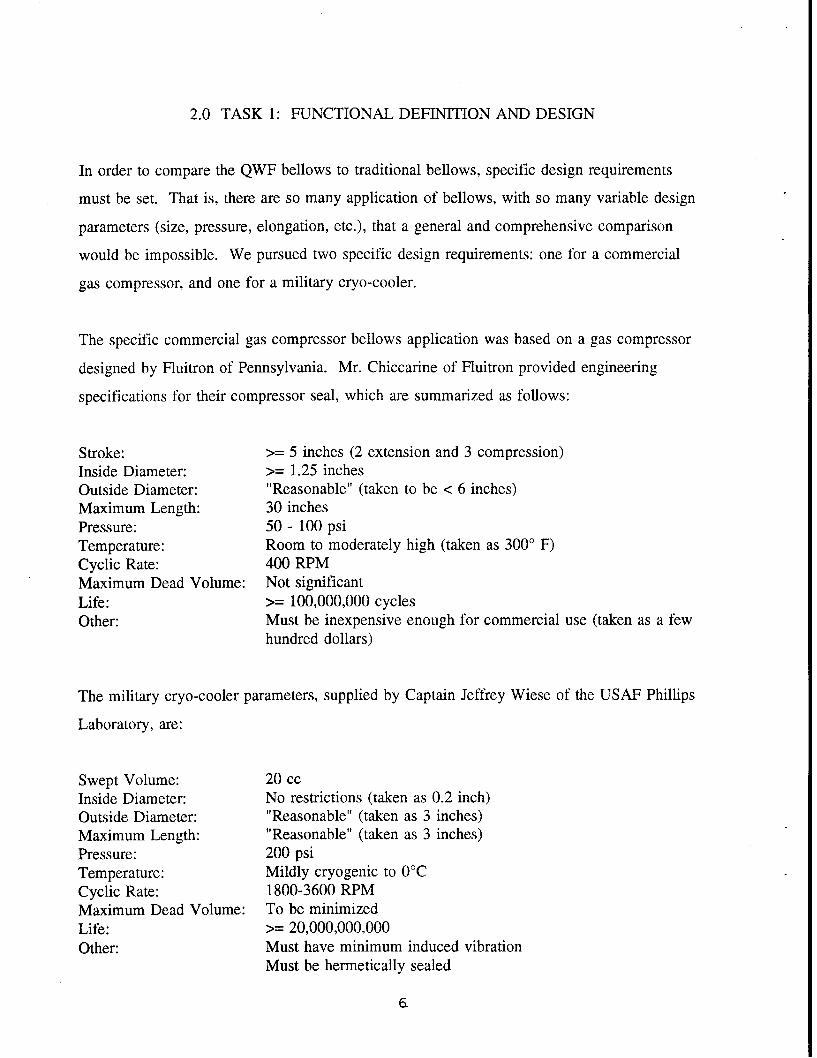
2.0 TASK 1: FUNCTIONAL DEFINITION AND DESIGN
In order to compare the QWF bellows to traditional bellows, specific design requirements
must be set. That is, there are so many application of bellows, with so many variable design
parameters (size, pressure, elongation, etc.), that a general and comprehensive comparison
would be impossible. We pursued two specific design requirements: one for a commercial
gas compressor, and one for a military cryo-cooler.
The specific commercial gas compressor bellows application was based on a gas compressor
designed by Fluitron of Pennsylvania. Mr. Chiccarine of Fluitron provided engineering
specifications for their compressor seal, which are summarized as follows:
Stroke: >= 5 inches (2 extension and 3 compression)Inside Diameter: >= 1.25 inchesOutside Diameter: "Reasonable" (taken to be < 6 inches)Maximum Length: 30 inchesPressure: 50 - 100 psiTemperature: Room to moderately high (taken as 3000 F)Cyclic Rate: 400 RPMMaximum Dead Volume: Not significantLife: >= 100,000,000 cyclesOther: Must be inexpensive enough for commercial use (taken as a few
hundred dollars)
The military cryo-cooler parameters, supplied by Captain Jeffrey Wiese of the USAF Phillips
Laboratory, are:
Swept Volume: 20 ccInside Diameter: No restrictions (taken as 0.2 inch)Outside Diameter: "Reasonable" (taken as 3 inches)Maximum Length: "Reasonable" (taken as 3 inches)Pressure: 200 psiTemperature: Mildly cryogenic to 00CCyclic Rate: 1800-3600 RPMMaximum Dead Volume: To be minimizedLife: >= 20,000,000,000Other: Must have minimum induced vibration
Must be hermetically sealed
6.
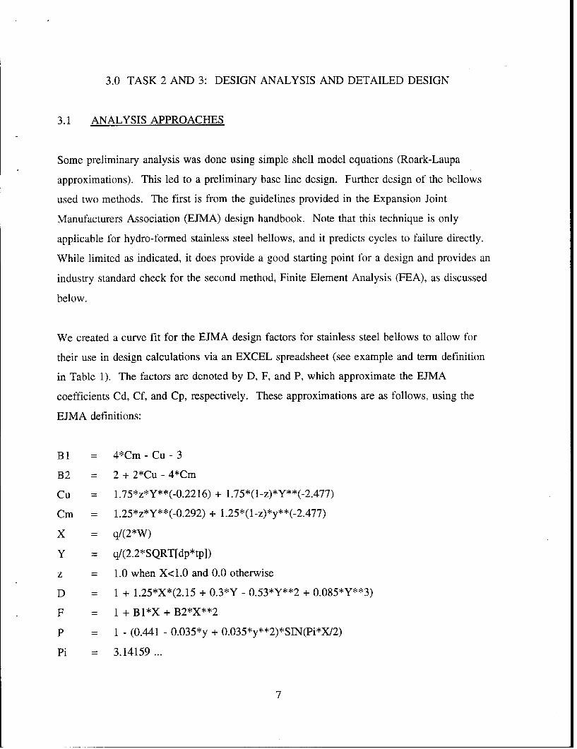
3.0 TASK 2 AND 3: DESIGN ANALYSIS AND DETAILED DESIGN
3.1 ANALYSIS APPROACHES
Some preliminary analysis was done using simple shell model equations (Roark-Laupa
approximations). This led to a preliminary base line design. Further design of the bellows
used two methods. The first is from the guidelines provided in the Expansion Joint
Manufacturers Association (EJMA) design handbook. Note that this technique is only
applicable for hydro-formed stainless steel bellows, and it predicts cycles to failure directly.
While limited as indicated, it does provide a good starting point for a design and provides an
industry standard check for the second method, Finite Element Analysis (FEA), as discussed
below.
We created a curve fit for the EJMA design factors for stainless steel bellows to allow for
their use in design calculations via an EXCEL spreadsheet (see example and term definition
in Table 1). The factors are denoted by D, F, and P, which approximate the EJMA
coefficients Cd, Cf, and Cp, respectively. These approximations are as follows, using the
EJMA definitions:
BI = 4*Cm - Cu - 3
B2 = 2 + 2*Cu - 4*Cm
Cu = 1.75*z*Y**(-0.2216) + 1.75*(1-z)*Y**(-2.477)
Cm = 1.25*z*Y**(-0.292) + l.25*(l-z)*y**(-2.477)
X = q/(2*W)
Y = q/(2.2*SQRT[dp*tp])
z = 1.0 when X<1.0 and 0.0 otherwise
D = 1 + 1.25*X*(2.15 + 0.3*Y - 0.53*Y**2 + 0.085*Y**3)
F = + Bl*X + B2*X**2
P = 1 - (0.441 - 0.035*y + 0.035*y**2)*SIN(Pi*X/2)
Pi = 3.14159 ...
7

Table 1. Example EXCEL spreadsheet and EJMA term definitions.
1 2 3 4 5 6 7 8p e O.R. I.R. d q t w
(psi) (in) (in) (in) (in) (in) (in) (in)1 100 0.00505 1.36 0.625 1.29 0.2 0.02 0.715
100 0.00505 1.904 0.625 1.29 0.2 0.02 1.2593 1001 0.00505 2.72 0.625 1.29 0.2 0.02 2.0754 100 0.003535 1.36 0.625 1.29 0.2 0.02 0.7151 100 0.003535 1.904 0.625 1.29 0.2 0.02 1.2596 100 0.003535 2.72 0,625 1.29 0.2 0.02 2.0757 50 0.00505 1.36 0.625 1.29 0.2 0.02 0.7158 50 0.00505 1.904 0.625 1.29 0.2 0.02 1.2599 50 0.00505 2.72 0.625 1.29 0.2 002 2.075
10 50 0.003535 1.36 0.625 1.29 0.2 0.02 0.71511 50 0.003535 1.904 0,625 1.29 0.2 0.02 1.25912 50 0.003535 2.72 0.625 1.29 0.2 0.02 2.07513 100 0.00505 1.36 0.625 1.29 0.2 0.015 0.7214 110 0.00505 1.904 0.625 1.29 0.2 0.015 1.26415 100 0.00505 2.72 0.625 1.29 0.2 0.015 2.0816 100 0.003535 1.36 0.625 1.29 0.2 0.015 0.7217 100 0.003535 1.904 0,625 1.29 0.2 0.015 1.26418 100 0.003535 2.72 0,625 1.29 0.2 0.015 2.0819 50 0.00505 1.36 0.625 1.29 0.2 0.015 0.7220 50 0.00505 1.904 0.625 1.29 0.2 0.015 126421 50 0.00505 2.72 0.625 1.29 0.2 0.015 2.0822 50 0.003535 1.36 0.625 1.29 0.2 0.015 0.7223 50 0.003535 1.904 0.625 1.29 0.2 0.015 1.26424 50 0.003535 2.72 0.625 1.29 0.2 0.015 2.0825 100 0.00505 1.36 0.625 1.29 0.2 0.015 0.7226 100 0.00505 1.904 0.625 1.29 0.2 0.015 1.26427 100 0.00505 2.72 0.625 1.29 0.2 0.015 2.0828 100 0.003535 1.36 0.625 1.29 0.2 0.015 0.7229 100 0.003535 1.904 0.625 1.29 0.2 0.015 1.26430 100 0.003535 2.72 0.625 1.29 0.2 0.015 2.0831 50 0.00505 1.36 0.625 1.29 0.2 0.015 0.7232 50 0.00505 1.904 0.625 1.29 0.2 0.015 1.26433 50 0.00505 2.72 0.625 1.29 0.2 0.015 2.0834 50 0.003535 1.36 0.625 1,29 0.2 0.015 0.7235 50 0.003535 1.904 0.625 1.29 0.2 0.015 1.26436 50 0.003535 2.72 0.625 1.29 0.2 0.015 2.0837 100 0.00505 1.36 0.625 1.29 0.1 0.02 0.71538 100 0.00505 1.36 0.625 1.29 0.4 0.02 0.715
8

O 0''300'cN O -'-034L3" 1 c U C ll r l 0r'VC'303r". 'C' Z0 034CO 3' (N . ' 4q C)0"
E 3 "3 (N 10' C-4' -l (N0 (N'0 '0( 0' Lo0Co , 0 - (N (3 M -, 0' QL1 "2 - > -
o 0' - 'o o - 0 -- 0' -0 v3 '0' 3 000 ' 0 0 O '0 0 '0 C00104 0 0' 3 0(3
.0'0 M' 0.( Nm('3:C1,'0 " 30 r'0 r. ( N -10 1 ' 0-' "R . r'..rq o 0
0, 03 Z' 2' C> - 23 0' 0 ''p3 '0 17 M zo M0 M' >
'1 1# - 1' -121 0' 5-0! 0
'0 c i c _j lq u 0' 0 0 '0 3 0 O 0 ' 0 0 0 0 O ~ ' o0 -o
'0' ' ! - - 3 ' 0 0 4 . -'0 0''0 N 0 -'0 0'i 3 0 - '0 0 ' 3 " 0 '00"0 -0 0 - l 0-
o oo 6 06 "R0 o a C ' ) t 0C
0' 0 0 3 0 C 4 (N00 ( 0 ( N N( (N (NT ('4 ' 0 ' 03 qN N N ( N ('3 0 0 n ' 0 3'
C-4.0 'o-n010L qv ' 00 (N03 co3 '03 m'3 v . . 0 0 . 3)3
(N of l .03 5 03 (N : '03 - O - '0 (N" M (" 0 '0 vN" 0 (N v3 c'Z " d f 'd - e 3- ' 3 N(
-0d 01 0m2 5L 141)io o)V OC) l 0m L
-~~~0 ' V,2OO''''O0O0 OOOO0O0 ''''''''''''0 ' -0 -0 0 V 0 0 3aooo ooo ooo oooo0oo ooo ooo04oo 0oo
C.) 0 0'('3 30', 00 30 C0'r.N 'r-(N ".( o'r N-~N '' N'N N 'N N'
0) Z >v o " O C
CN" 'q " ' 'a00 3( as(N " 16 vs M N r 0( I"~ C (N(N0(N r 0(N M(N 0
. . . . . .. . . . . .-. - 0~ 0 - ~ 0 -
0 N0 '( '0 (N'q -l lq l C) ' (N~ q cl l 03 0303 ('3 - .9 -' -q v3" -0 3 " -'o 'o -o q '0 " - N 0q C 00-0 0 'o OmO'' o '0 O' O O'd'0O '0 O 0 ' 30 "
'00 '0 ' 3 ' 0 ' 0 0 ' 0 0 3 ' 3 3 0 0 3 0 0 0 03 3 0 C C) CI m34 0 03 "3 V ''
>(v'0o I q O ' U'' "30 ' '0-'3( Lo3N33( 00( 030(N003N033( 030(N 30 0q-(" 3 0 (N "3 0 (N "3 0 (N " 3 0 :0 '0.' 0 ' 0 0 - ' 0 3 , ' 0 0 3 -' q0
(N 0 0 C '0 (N' '0 (N ' (N 0-' (N 03 03 r' 3-( 0 -( 0 (Ni 0 CN. dN 0
00 00 00 00 0'0 0' ' 0'0 0 ' ' '0 00 0' 00 0'4 00 0' 0 Lo(
-'~ ~~- O"0 (00 "3.0 VN" '0 (N 4300''0 030' 00330030 '0'0' '00' ('o':0, 0 LO3 ( N '00 "3k 03" 03 0 3 "3- 0 3 o" 03 03 i "3- d
3 ' 0 0 - 00 - 0 - -0 0 C' 0 -00- -000(
o ? " -c00 - 0 - 0~ 0 0 ~ 0 30 8 0
0 > 2!C 0 00 00 00 q ' 00 'o do ooo 00 >' O OqMC 00 d
LO (N ('3 3" C ' 0 (N 0 0' 0 4- ( 0' ' 0 " ( 03 0' 0 0- C'J (' 03 '0 (N 0 0 ' Ci 0 0 (N 0' 'l 04 30 N 03- - - - - - - -- - - - - -7 Oi((N(N N(N(N (N((:N0 l C '3('3( ' ! (' (
cl C N O - Cj v N o : -C4 f -c 6c u : 4LO0
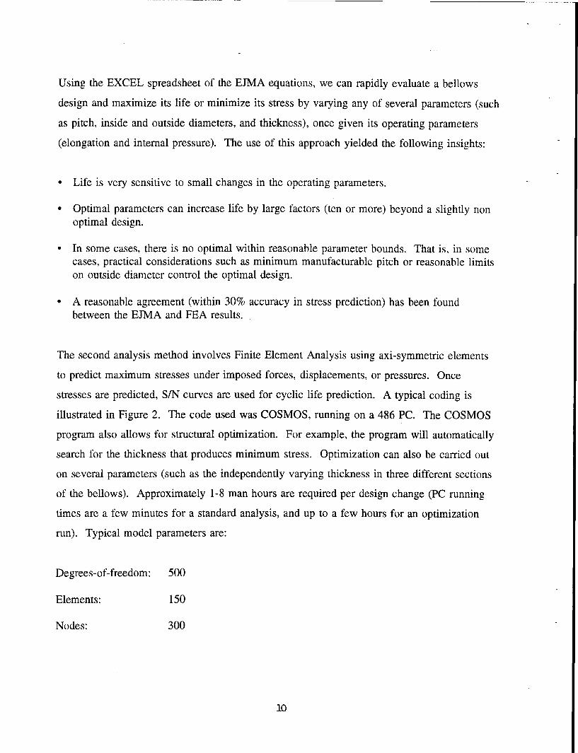
Using the EXCEL spreadsheet of the EJMA equations, we can rapidly evaluate a bellows
design and maximize its life or minimize its stress by varying any of several parameters (such
as pitch, inside and outside diameters, and thickness), once given its operating parameters
(elongation and internal pressure). The use of this approach yielded the following insights:
* Life is very sensitive to small changes in the operating parameters.
* Optimal parameters can increase life by large factors (ten or more) beyond a slightly nonoptimal design.
* In some cases, there is no optimal within reasonable parameter bounds. That is, in somecases, practical considerations such as minimum manufacturable pitch or reasonable limitson outside diameter control the optimal design.
* A reasonable agreement (within 30% accuracy in stress prediction) has been foundbetween the EJMA and FEA results.
The second analysis method involves Finite Element Analysis using axi-symmetric elements
to predict maximum stresses under imposed forces, displacements, or pressures. Once
stresses are predicted, S/N curves are used for cyclic life prediction. A typical coding is
illustrated in Figure 2. The code used was COSMOS, running on a 486 PC. The COSMOS
program also allows for structural optimization. For example, the program will automatically
search for the thickness that produces minimum stress. Optimization can also be carried out
on several parameters (such as the independently varying thickness in three different sections
of the bellows). Approximately 1-8 man hours are required per design change (PC running
times are a few minutes for a standard analysis, and up to a few hours for an optimization
run). Typical model parameters are:
Degrees-of-freedom: 500
Elements: 150
Nodes: 300
10

1A LI g> w J i
LI
If)
I--
Figure 2. Typical QWF COSMOS configuration.
1-1

COSMOS is capable of exercising a large displacement model, but this was not used in these
analyses, as simple calculations indicated it was not a factor. It may be useful in future
analyses to use COSMOS to further check the effect of large displacements on these results.
3.2 RESULTS OF COMPRESSOR STUDY
With regards to the Fluitron compressor example, we achieved interesting and enlightening
conclusions using the EJMA and FEA approaches. This example used the following
additional parameters:
Inside radius: 0.625"
Pressure: 50 psi
Pitch: 0.3" (set at this lower limit by reasonable manufacturing limits)
Elongation: 0.03"/convolution (thus can get 3 inches with 100 convolutions and meet a30-inch length limit)
Outside radius: As discussed below
Thickness: Allowed to vary to get optimal design, as discussed below.
The following four cases were run:
CASE A: Typical bellows with outside radius limited, by hydro-forming methods, to 1.4times the inner radius (hence equal to 0.875"). The optimal thickness of thisbellows was found to be 0.006", and it had a maximum VonMises stress of 78ksi.
CASE B: As in Case A, but using an outside diameter of 1.904 and consequently having aninside diameter limited by the 1.4 factor of 1.36". The optimal thickness of thisbellows was found to be 0.018", and it had a maximum stress of 62 ksi.
CASE C: A standard bellows, but one in which the outside to inside radius ratio is allowedto increase due to the possibilities allowed by the QWF manufacturing approach.For practical reasons, this outside radius was taken as 1.904" and the inner of0.625" (a ratio of 3.05). This bellows was found to have an optimal thickness of0.042", and a maximum stress of 41 ksi. Hence the radius choices offered by the
12

QWF design allows for a 0.53 - 0.66 reduction factor in peak stress from Cases Aand B.
CASE D: A standard-shaped bellows with the 1.904 outside radius and 0.625 inside radius,but one in which the thickness of the bellows is allowed to vary in three areas(roughly the inner, middle, and outer 1/3 of the convolution). The optimalthickness of this bellows was found to be 0.0196", 0.0425", and 0.0658" in thethree areas. The maximum stress was 28 ksi. Hence a variable thickness QWFbellows allows for a 0.36 - 0.45 reduction factor in peak stress from Cases A andB (and a 0.68 reduction factor from Case C).
These large stress reductions lead to greatly increased lifetimes. For example, Cases C and D
are below the endurance limit of stainless steel and would probably have life in excess of
1,000,000,000. (This life can only be estimated roughly, as the fatigue data for stainless steel
[and most materials] at one billion cycles is limited and uncertain.) Cases A and B, using
standard bellows designs, are predicted to have lives under 1,000,000 cycles. This example
indicates that the QWF approach has the ability to yield very significant improvements in
bellows performance. Further, additional optimization of the design is possible (e.g., more
regions of variable thickness).
3.3 RESULTS OF CRYO-COOLER STUDY
Analyses of this design were not conducted, within the limits of this project effort.
3.4 A BELLOWS FIGURE OF MERIT
The evaluation of bellows can be approached from the computation or demonstration of their
anticipated life, or maximum stress. Alternately, some more general points can be made by
reference to "figures of merit" which seek to compare bellows more generally, emphasizing
their structural, thermodynamic, or longevity, or all three. Appendix A presents a discussion
of such figures of merit.
13

14

4.0 TASK 4: MANUFACTURE
The goal of this task was to determine ways of manufacturing a QWF bellows, and to
fabricate a prototype. Manufacturing techniques were identified and bellows components
were fabricated. They were not assembled into a final bellows due to difficulties encountered
in the bellows fabrication.
4.1 STANDARD FABRICATION TECHNIQUES INVESTIGATED
Standard fabrication techniques that were investigated included:
Furnace brazing. This method has the ability to bond similar and dissimilar metals byplacing a bonding (brazing) compound between the two surfaces to be joined, clampingthe two pieces, and heating in an oven for up to several hours. The technique works wellfor lap joints but not, in general, for butt joints. Due to the elevated temperatures used,this technique may have possible effect on fatigue life, in that it may anneal the coldworking of the formed component that leads to increased fatigue life. Evaluation of thiseffect would require actual fatigue testing of manufactured prototypes.
* Inertial (friction) welding has an even greater ability to weld dissimilar metals. However,our investigations indicated that its requirement of thick connection cross sections at thebond area probably make it unsuitable for QWF bellows manufacturing.
" EDM wire cutting capabilities to use hydro-formed bellows as feed stock for QWFmanufacturing. This technique can cut very thin sections. However, some difficulty wasencountered in trying to use EDM cutting on formed bellows, as discussed below.
4.2 ALTERNATE MATERIALS AND FABRICATION TECHNIQUES
This project also sought to evaluate the feasibility of using nano-crystalline nickel (or other
unique materials) in bellows construction and to use unique manufacturing techniques (such
as possible with electrodeposition and machined bellows). These issues were investigated by
conducting 2-3 hour meetings with various experts:
• Richard Edwards and Glen Malone of Electroformed Nickel, a company involved with thedesign and manufacture of electroformed nickel products.
15
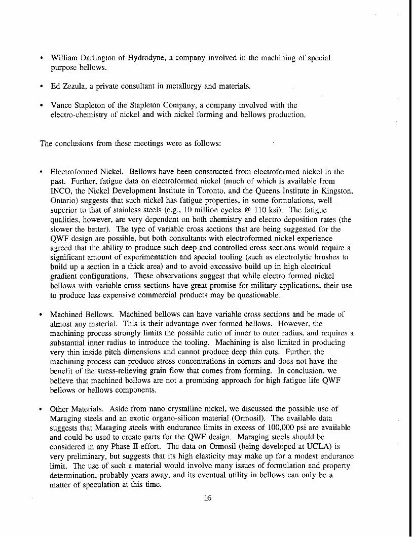
• William Darlington of Hydrodyne, a company involved in the machining of specialpurpose bellows.
* Ed Zezula, a private consultant in metallurgy and materials.
* Vance Stapleton of the Stapleton Company, a company involved with theelectro-chemistry of nickel and with nickel forming and bellows production.
The conclusions from these meetings were as follows:
* Electroformed Nickel. Bellows have been constructed from electroformed nickel in thepast. Further, fatigue data on electroformed nickel (much of which is available fromINCO, the Nickel Development Institute in Toronto, and the Queens Institute in Kingston,Ontario) suggests that such nickel has fatigue properties, in some formulations, wellsuperior to that of stainless steels (e.g., 10 million cycles @ 110 ksi). The fatiguequalities, however, are very dependent on both chemistry and electro deposition rates (theslower the better). The type of variable cross sections that are being suggested for theQWF design are possible, but both consultants with electroformed nickel experienceagreed that the ability to produce such deep and controlled cross sections would require asignificant amount of experimentation and special tooling (such as electrolytic brushes tobuild up a section in a thick area) and to avoid excessive build up in high electricalgradient configurations. These observations suggest that while electro formed nickelbellows with variable cross sections have great promise for military applications, their useto produce less expensive commercial products may be questionable.
" Machined Bellows. Machined bellows can have variable cross sections and be made ofalmost any material. This is their advantage over formed bellows. However, themachining process strongly limits the possible ratio of inner to outer radius, and requires asubstantial inner radius to introduce the tooling. Machining is also limited in producingvery thin inside pitch dimensions and cannot produce deep thin cuts. Further, themachining process can produce stress concentrations in corners and does not have thebenefit of the stress-relieving grain flow that comes from forming. In conclusion, webelieve that machined bellows are not a promising approach for high fatigue life QWFbellows or bellows components.
" Other Materials. Aside from nano crystalline nickel, we discussed the possible use ofMaraging steels and an exotic organo-silicon material (Ormosil). The available datasuggests that Maraging steels with endurance limits in excess of 100,000 psi are availableand could be used to create parts for the QWF design. Maraging steels should beconsidered in any Phase II effort. The data on Ormosil (being developed at UCLA) isvery preliminary, but suggests that its high elasticity may make up for a modest endurancelimit. The use of such a material would involve many issues of formulation and propertydetermination, probably years away, and its eventual utility in bellows can only be amatter of speculation at this time.
16

4.3 FABRICATION UNDERTAKEN
Bellows were purchased from a major formed bellows manufacturer (Robertshaw), based on
preliminary calculations, to allow preliminary investigations into fabrication techniques
(cutting, brazing, etc.), and for testing to evaluate effects of annealing due to furnace brazing.
Other materials were obtained to perform basic fabrication.
The bellows were cut using EDM techniques. These preliminary efforts indicated a great
difficulty in producing clean uniform cuts. Additional work needs to be done to show if this
method of providing QWF base parts is practical.
Typical thicknesses of stainless steel in straight sections were furnace brazed to develop
experience in this method. These proved to develop a very good bond. Further efforts are
required to show that this method is practical for dished circular sections. These were not
done due to the difficulties mentioned above with the cutting of the formed bellows.
17

18
5.0 TASK 5: TEST PROGRAM
Testing of prototype bellows was not conducted, as none were fabricated, within the limits of
this project effort.
The intent of this task, in the event that additional efforts can be carried out in the future, was
as follows. Two bellows were to be tested, one a standard formed bellows and one a
fabricated QWF bellows. The testing was intended to demonstrate the higher fatigue life of
the QWF bellows.
In order to perform the fatigue testing, ANCO was to use a fatigue testing fixture capable of,
nominally, 30 cycles/second, 0.4 inch (1 cm) stroke, 50 pound (220 N) force, and 10
atmosphere pressure.
19

6.0 ADDITIONAL TASKS PERFORMED
As mentioned above, not all the original tasks were completed as originally envisioned. By
its very nature, research cannot predict exactly at its onset what it will investigate and
discover. In our initial proposal and contract, we proposed assembling a sample QWF
bellows and fatigue testing it as an approach to determining the feasibility of a QWF bellows
design. However, in the course of our work, we encountered difficulties in the manufacture
that led us to investigate other manufacturing approaches. While we did not, in the end,
fabricate and test a complete prototype (due to the discovery that EDM cutting was not
immediately feasible), we did find out what we believe are very significant ways to fabricate
optimal bellows.
When we encountered difficulty with the EDM method of producing QWF parts, and the
FEM analysis indicated the great benefit of continuously varying wall thickness, rather than
just two wall thicknesses, we began to look more closely at the advantages of electroforming
and its ability to produce variable wall thickness, and especially electroformed Nickel. This
led to extra efforts, summarized in the sections below. We investigated one newly discovered
material (Ormosil) which also allowed for the possibility of variable wall thickness, and an
alternate bellows design approach (non circular bellows). We also investigated to a greater
extent than originally planned several additional commercialization possibilities.
6.1 NANOCRYSTALINE NICKEL
Additional work was performed to gather the properties of Nanocrystaline and electroformed
Nickel, including conversations and contacts with INCO, the Nickel Development Institute in
Toronto, and the Queens Institute in Kingston, Ontario. This work also sought additional
infomation on the factors which affected the fatigue strength of electroformed Nickel, and
the experience in producing bellows or bellows like objects by these methods. As discussed
elsewhere in this final report, the use of electroformed Nickel to produce bellows of variable
thickness optimized to a specific application is considered to be the most promising approach
for future investigations for military and aerospace bellows that was identified by this study.
21

6.2 ORMOSIL
Professor McKenzie at UCLA has been investigating an organo-silicon compound he calls
Ormosil. This material can be compounded with elastic properties ranging from soft rubber
to hard plastics, and has been suggested for use in golf ball covers, shoe soles, artificial organ
replacements, and many other mechanical devices. Of particular interest is the potential to
cast Ormosil in almost any shape, including a variable thickness bellows. While only
preliminary information is available on its elastic properties, and almost no data is available
on its fatigue properties, its greater flexibility and operability over a very wide temperature
range suggests that it may be useful in bellows design. The use of this material, in one of its
many formulations, would involve many issues of formulation and property determination.
Such information, we discovered, is probably years away, and its eventual utility in bellows
design can only be a matter of speculation at this time.
6.3 NON-CIRCULAR BELLOWS
Some additional effort was spent on the investigation of non circular bellows in an effort to
take the advantage of the low stresses in a large radius bellows (as opposed to a smaller
radius bellows), and yet allow the larger bellows to be fit into a smaller space (see attached
sketch). Methods of fabrication considered were cutting segments out of a large bellows and
uniting them to produce an oblong bellows, and the stretch forming of corrugated sheet to
produce segments that could be joined into an oblong bellows.
6.4 ADDITIONAL COMMERCIALIZATION OPPORTUNITIES
Several additional organizations were contacted to ascertain their interest in various bellows
concepts, including the Gas Research Institute (gas compressors), the University of Houston
(petrochemical product compressors), and Calstart (automotive gaseous fuel compressors).
22

7.0 CONCLUSIONS AND ANTICIPATED PHASE II RESEARCH AND DEVELOPMENT
7.1 CONCLUSIONS FROM PHASE 1
In summary, the conclusions of the Phase I effort are:
" The QWF design has the potential of much longer life than a standard formed bellows.
* The most promising design feature is a variable thickness bellows. Stress reductions of afactor of two or larger compared to a standard formed bellows is possible. This can resultin an enormous increase in fatigue life. Such bellows can also have low dead volume.
" Nano crystalline electroformed nickel has the greatest potential for producing highperformance military bellows, but may be too expensive for commercial products. This isespecially true because of the ability to produce a variable thickness by electroforming.
" An optimal bellows can only be defined for a specific set of design parameters. Smallchanges in these parameters can significantly change the configuration of the optimalbellows.
* The EJMA computations, when implemented on a spreadsheet, are very useful fordemonstrating trends and performing initial optimal designs. Preliminary results indicatedthat it, as well as the commercial design, would benefit greatly from a variable thicknessdesign.
" FEA methods are essential for analyzing variable thickness bellows and are useful toproduce optimal designs.
* Furnace brazing may be useful in producing fabricated QWF bellows. Friction weldingand machining are not, although some additional investigation into friction welding maybe warranted.
* Fatigue data is available for stainless steel, Maraging steel, and nickel at high numbers ofcycles, but is just barely sufficient.
" Maraging steel may be superior to stainless steels for formed bellows.
7.2 RECOMMENDED PHASE II RESEARCH AND DEVELOPMENT
The successful conduct of Phase II will require a clear definition of the standard applications
to be selected, and a reasonable number of design and design variables that will be investi-
23
gated. This goal is primary, due to the multitude of facets facing the designer of a new
bellows (geometry, material, fabrication techniques, applications, etc.).
In addition, the Phase II effort must be defined with a clear definition of commercialization
possibilities. These will include input from compressor manufacturers such as Fluitron,
cryo-cooler users, natural gas compressor users, nuclear applications, and others.
The following are among the tasks and issues to be addressed in a Phase II effort:
• Extensive evaluation of variable thickness electroformed nanocrystaline bellows should bemade. This approach appears to be the most promising at this time.
" Several prototypes must be fabricated and fatigue tested.
" The EJMA analysis of the military cryo-cooler, not performed herein, should be carriedout.
* Improved EDM technique should be further investigated, so as to determine if standardformed bellows can provide components of a QWF design.
* Large displacement FEA stress models should be checked to make sure that the smalldisplacement assumptions are justified.
24

APPENDIX A
DISCUSSION ON BELLOWS FIGURES OF MERIT
The history of technology provides numerous examples of benefits resulting from
identification and formulation of a single parameter which can be called a figure of merit.
For example, in the design of hydraulic and pneumatic accumulators for the aerospace
industry, a product similar to metal bellows in many respects, a significant improvement was
made in the ratio of maximum energy stored to gross weight of the accumulator after this
ratio was widely accepted as a useful figure of merit by much of the accumulator industry.
Other segments of the aerospace industry have sometimes adopted efficiency and other
dimensionless figures of merit. Among metal bellows, where dimensions can span a very
large range of values, it would be more desirable if the figure of merit could also be
dimensionless.
For years, a few preliminary design analysts have considered the ratio of maximum allowable
thermodynamic work per cycle (pneumatic energy per stroke) to total strain energy per cycle
as a preliminary criterion of the merit of a bellows. Accordingly, this ratio was one of
several criteria used to compare some of the early designs aimed at meeting the above
Fluitron bellows criteria. At best, it proved to be only somewhat helpful. This pneumatic-
energy-to-strain-energy figure of merit is an oversimplification in at least two obvious ways.
One is the omission of consideration of the bellows dead volume (the fully-compressed
bellows clearance volume) as a factor in the formula. This is a big omission because many
applications cannot tolerate a large dead volume and because large dead volume is often an
easy way to enable a bellows to have less maximum stress.
Another deficiency in the above energy-ratio figure of merit is a sensitivity to how the loads
are applied, particularly to the ratio of axial force and total axial pressure load. For example,
a bellows compressed by a fluid can be expected to show a larger value of this particular
merit figure than the same bellows cranked mechanically. In general, to be most simple and
useful, the bellows figure of merit should be a function of bellows dimensions and parameters
only. The above energy-to-ratio figure of merit does this if applied only to the case of a
25

particular ratio of axial load to pressure load. It can be calculated entirely from data given in
some stock bellows catalogs.
An effort was made to improve on the above merit formulation by introducing a dead volume
term. Although dead volume is known to be an important part of the specification of bellows
used in both cryo-coolers and compressors, the particular bellows specification that was
recommended by Fluitron was somehow an exception to this. Even after numerous telephone
calls, the reason for Fluitron giving zero weight to the dead volume term has not been
understood. In the case of Stirling cycle cryo-coolers, even the simplest type of cycle
analysis, the Schmidt analysis, provides a connection between dead volume and efficiency.
Using that analysis, it is possible to make a good case for adopting a non-dimensional
bellows figure of merit:
FM = (allowable work per cycle)/([dead volume] [maximum bellows stress])
26

DISTRIBUTION LIST
AUL/LSEBldg 1405 - 600 Chennault CircleMaxwell AFB, AL 36112-6424 1 cy
DTIC/OCP8725 John J. Kingman Rd Ste 944FT Belvoir, VA 22060-6218 2 cys
AFSAA/SAI1580 Air Force PentagonWashington, DC 20330-1580 1 cy
PL/SULKirtland AFB, NM 87117-5776 2 cys
PL/HOKirtland AFB, NM 87117-5776 1 cy
Official Record Copy
PL/VTPT/Capt Jeffrey Wiese 2 cys
Dr. R. V. Wick I cyPL/VTKirtland, AFB, NM 87117-5776
27