Embed Size (px)
Citation preview

SolidWorks 2004 Tutorial
and MultiMedia CD
A Step-by-Step Project Based Approach Utilizing 3D Solid Modeling
David C. Planchard & Marie P. Planchard
SDC
Schroff Development Corporation
www.schroff.com www.schroff-europe.com
PUBLICATIONS
INSIDE:
MultiMedia CD
An audio/visual presentation of the
tutorial projects
Copyrighted Material
Copyrighted
Material
Copyrighted Material
Copyrighted
Material PAGE 1 - 1
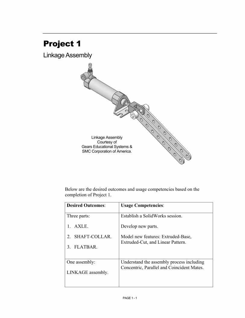
Project 1 Linkage Assembly
Below are the desired outcomes and usage competencies based on the completion of Project 1.
Desired Outcomes: Usage Competencies:
Three parts:
1. AXLE.
2. SHAFT-COLLAR.
3. FLATBAR.
Establish a SolidWorks session.
Develop new parts.
Model new features: Extruded-Base, Extruded-Cut, and Linear Pattern.
One assembly:
LINKAGE assembly.
Understand the assembly process including Concentric, Parallel and Coincident Mates.
Linkage Assembly Courtesy of
Gears Educational Systems & SMC Corporation of America.

Copyrighted Material
Copyrighted
Material
Copyrighted Material
Copyrighted
Material
Linkage Assembly SolidWorks Tutorial
PAGE 1 - 2
Notes:

Copyrighted Material
Copyrighted
Material
Copyrighted Material
Copyrighted
Material
SolidWorks Tutorial Linkage Assembly
PAGE 1 - 3
Project 1 – Extrude Features
Project Objective
Provide an understanding of the SolidWorks User Interface: Menus, Toolbars, System feedback, Keyboard shortcuts, Document Properties, Templates, Parts and Assemblies.
Obtain the knowledge of the following SolidWorks features: Extruded-Base, Extruded-Cut and Linear Pattern.
Create three individual parts:
1. AXLE.
2. SHAFT-COLLAR.
3. FLATBAR.
Create a LINKAGE assembly.
On the completion of this project, you will be able to:
• Establish a SolidWorks session.
• Set units and the dimensioning standard.
• Create a part.
• Generate a sketch.
• Add dimensions.
• Add Geometric Relations.
• Download an assembly.
• Create an assembly.
• Use the following SolidWorks Features:
o Extruded-Base.
o Extruded-Cut.
o Linear Pattern.
Copyrighted Material
Copyrighted
Material
Copyrighted Material
Copyrighted
Material
Linkage Assembly SolidWorks Tutorial
PAGE 1 - 4
Project Overview
SolidWorks is a design automation software package used to produce and model parts, assemblies and drawings.
SolidWorks is a 3D solid modeling CAD program. SolidWorks provides design software to create 3D models and 2D drawings.
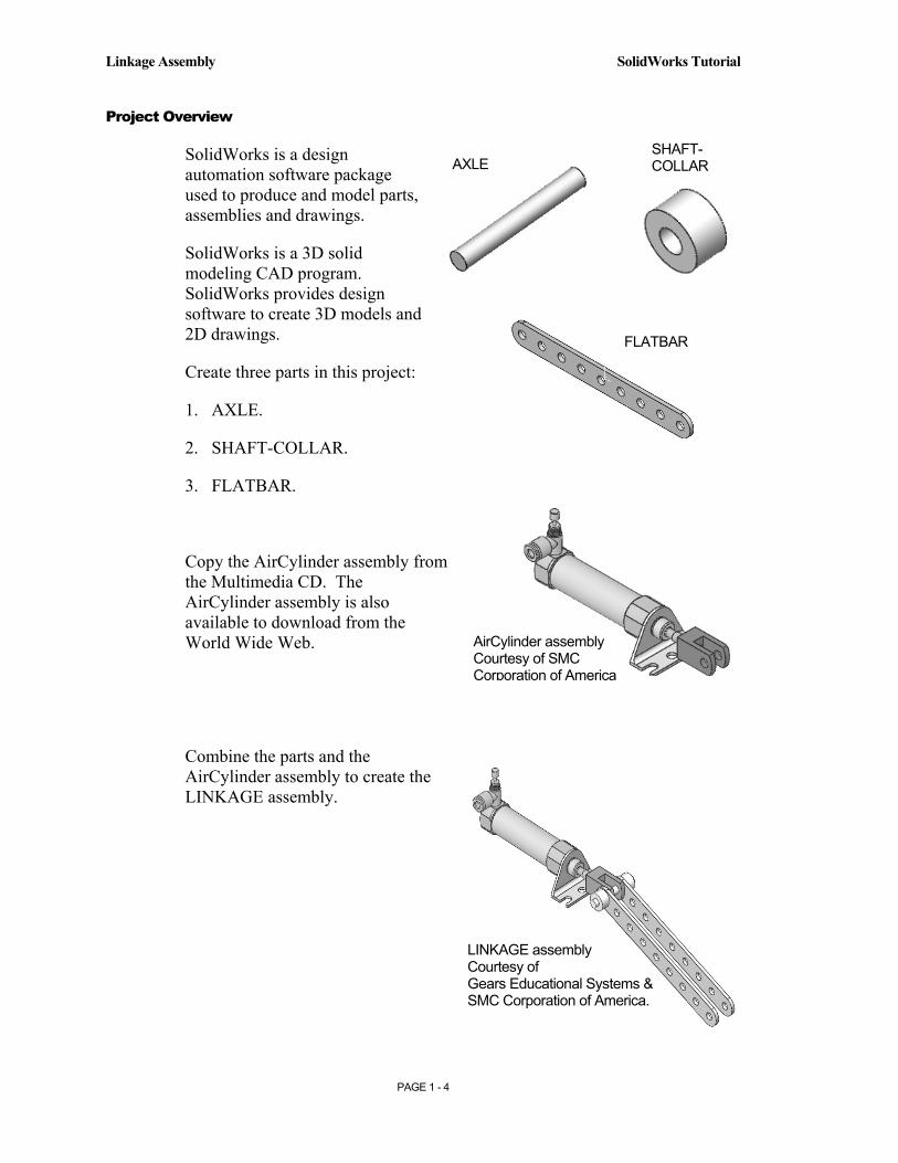
Create three parts in this project:
1. AXLE.
2. SHAFT-COLLAR.
3. FLATBAR.
Copy the AirCylinder assembly from the Multimedia CD. The AirCylinder assembly is also available to download from the World Wide Web.
Combine the parts and the AirCylinder assembly to create the LINKAGE assembly.
AXLE SHAFT-COLLAR
FLATBAR
LINKAGE assembly Courtesy of Gears Educational Systems & SMC Corporation of America.
AirCylinder assembly Courtesy of SMC Corporation of America

Copyrighted Material
Copyrighted
Material
Copyrighted Material
Copyrighted
Material
SolidWorks Tutorial Linkage Assembly
PAGE 1 - 5
AXLE Part
The AXLE is a cylindrical steel rod. Two AXLES support the two FLATBAR parts.
The AXLE rotates about its axis. The dimensions for the AXLE are determined from the other components in the LINKAGE assembly.
Start a new SolidWorks session. Create the AXLE part.
Use features to create parts. Features are building blocks that add or remove material.
Utilize the Extruded-Base feature. The Extrude Base features add material. The Base feature is the first feature of the part.
Sketch a circular profile on the Front plane, centered at the Origin.
Extend the profile perpendicular (⊥) to the Front plane.
Utilize symmetry. Extrude the sketch with the Mid Plane End Condition. The Extruded-Base feature is centered on both sides of the Front plane.
AXLE
FLATBAR
AXIS
Copyrighted Material
Copyrighted
Material
Copyrighted Material
Copyrighted
Material
Linkage Assembly SolidWorks Tutorial
PAGE 1 - 6
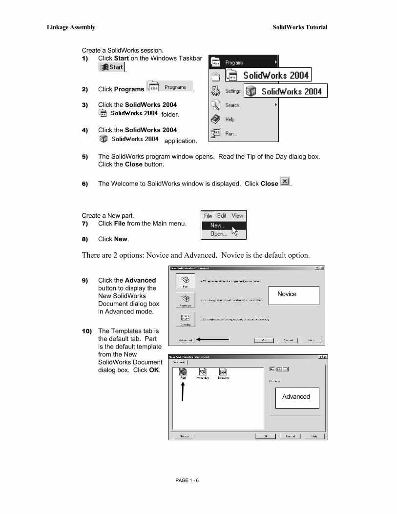
Create a SolidWorks session. 1) Click Start on the Windows Taskbar
.
2) Click Programs .
3) Click the SolidWorks 2004 folder.
4) Click the SolidWorks 2004 application.
5) The SolidWorks program window opens. Read the Tip of the Day dialog box. Click the Close button.
6) The Welcome to SolidWorks window is displayed. Click Close .
Create a New part. 7) Click File from the Main menu.
8) Click New.
There are 2 options: Novice and Advanced. Novice is the default option.
9) Click the Advanced button to display the New SolidWorks Document dialog box in Advanced mode.
10) The Templates tab is the default tab. Part is the default template from the New SolidWorks Document dialog box. Click OK.
Novice
Advanced
Copyrighted Material
Copyrighted
Material
Copyrighted Material
Copyrighted
Material
SolidWorks Tutorial Linkage Assembly
PAGE 1 - 7
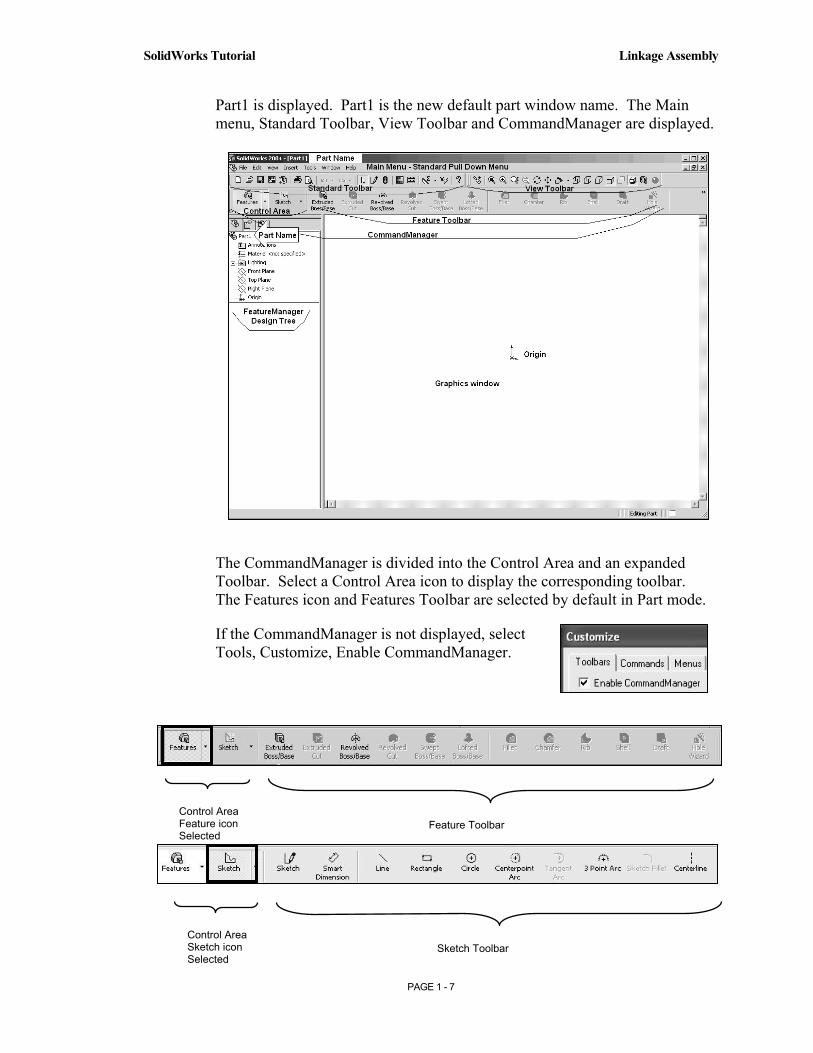
Part1 is displayed. Part1 is the new default part window name. The Main menu, Standard Toolbar, View Toolbar and CommandManager are displayed.
The CommandManager is divided into the Control Area and an expanded Toolbar. Select a Control Area icon to display the corresponding toolbar. The Features icon and Features Toolbar are selected by default in Part mode.
If the CommandManager is not displayed, select Tools, Customize, Enable CommandManager.
Control Area Sketch icon Selected
Sketch Toolbar
Control Area Feature icon Selected
Feature Toolbar
Copyrighted Material
Copyrighted
Material
Copyrighted Material
Copyrighted
Material
Linkage Assembly SolidWorks Tutorial
PAGE 1 - 8
Millimeters
Inches
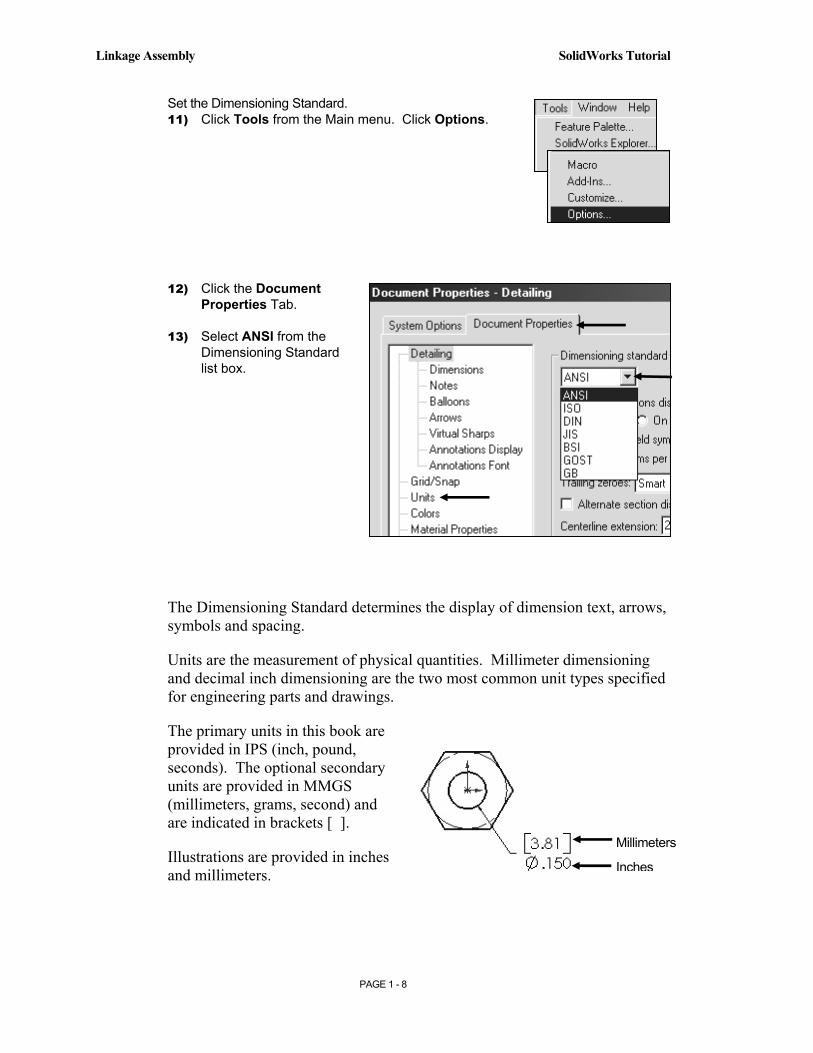
Set the Dimensioning Standard. 11) Click Tools from the Main menu. Click Options.
12) Click the Document Properties Tab.
13) Select ANSI from the Dimensioning Standard list box.
The Dimensioning Standard determines the display of dimension text, arrows, symbols and spacing.
Units are the measurement of physical quantities. Millimeter dimensioning and decimal inch dimensioning are the two most common unit types specified for engineering parts and drawings.
The primary units in this book are provided in IPS (inch, pound, seconds). The optional secondary units are provided in MMGS (millimeters, grams, second) and are indicated in brackets [ ].
Illustrations are provided in inches and millimeters.
Copyrighted Material
Copyrighted
Material
Copyrighted Material
Copyrighted
Material
SolidWorks Tutorial Linkage Assembly
PAGE 1 - 9
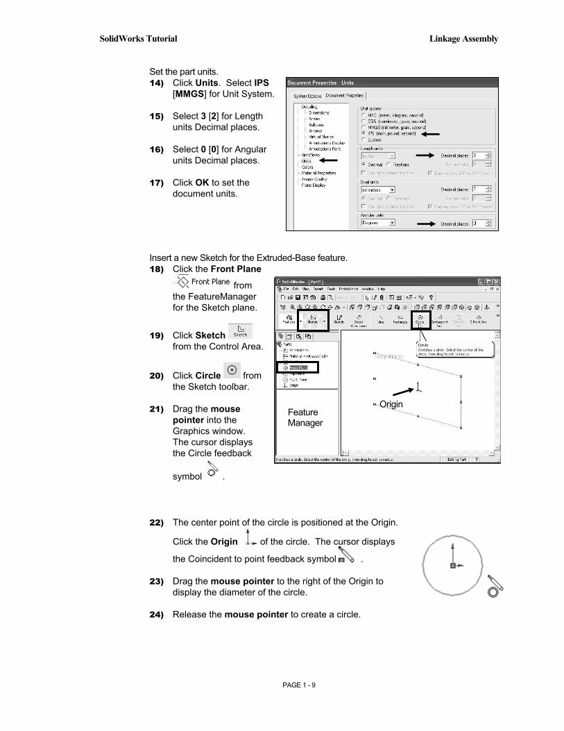
Set the part units. 14) Click Units. Select IPS
[MMGS] for Unit System.
15) Select 3 [2] for Length units Decimal places.
16) Select 0 [0] for Angular units Decimal places.
17) Click OK to set the document units.
Insert a new Sketch for the Extruded-Base feature. 18) Click the Front Plane
from the FeatureManager for the Sketch plane.
19) Click Sketch from the Control Area.
20) Click Circle from the Sketch toolbar.
21) Drag the mouse pointer into the Graphics window. The cursor displays the Circle feedback
symbol .
22) The center point of the circle is positioned at the Origin.
Click the Origin of the circle. The cursor displays
the Coincident to point feedback symbol .
23) Drag the mouse pointer to the right of the Origin to display the diameter of the circle.
24) Release the mouse pointer to create a circle.
Origin Feature Manager

Copyrighted Material
Copyrighted
Material
Copyrighted Material
Copyrighted
Material
Linkage Assembly SolidWorks Tutorial
PAGE 1 - 10
Dimension the circle.
25) Click Smart Dimension from the Sketch toolbar.
26) Click the circumference of the circle. The cursor displays the diameter
feedback symbol .
27) Click a position above the circle in the Graphics window to locate the dimension.
28) Enter .1875 [4.76] in the Modify dialog box. The diameter of the circle is .1875.
29) Click the Check Mark .
Three decimal places are displayed. The diameter value .1875 rounds to .188.
The circular sketch is centered at the Origin. The dimension indicates the diameter of the circle.
If your sketch is not correct, select UNDO .
Extrude the sketch to create the first feature.
30) Click Features from the Control Area.
31) Click Extruded Boss/Base from the Features toolbar. The Extrude PropertyManager is displayed.
Dimension position
Circumference

Copyrighted Material
Copyrighted
Material
Copyrighted Material
Copyrighted
Material
SolidWorks Tutorial Linkage Assembly
PAGE 1 - 11
32) The Graphics window displays an Isometric view of the sketch. Select Mid Plane for Direction 1 End Condition.
33) Enter 1.375 [34.93] for Distance.
34) Click OK to create the Extruded-Base feature.
35) Fit the model to the Graphics window. Press the f key.
The Extrude Property Manager displays the parameters utilized to define the feature. The Mid Plane End Condition in the Direction 1 box extrudes the sketch equally on both sides of the sketch plane. The Depth defines the distance.
The Extrude1 feature name is displayed in the FeatureManager. The FeatureManager lists the features, planes and other geometry that construct the part.
Extrude features add material. Extrude features require the following:
1. Sketch Plane.
2. Sketch.
3. Depth.
The sketch plane is the Front plane. The Sketch is a circle with the diameter of .1875 [4.76]. The Depth is 1.375 [34.93].
Sketch1 is displayed in the FeatureManager if you exit the Sketch before selecting Extrude Boss/Base. Click Sketch1 from the FeatureManager.
Click Extrude Boss/Base to create the feature.
FeatureManager
Copyrighted Material
Copyrighted
Material
Copyrighted Material
Copyrighted
Material
Linkage Assembly SolidWorks Tutorial
PAGE 1 - 12
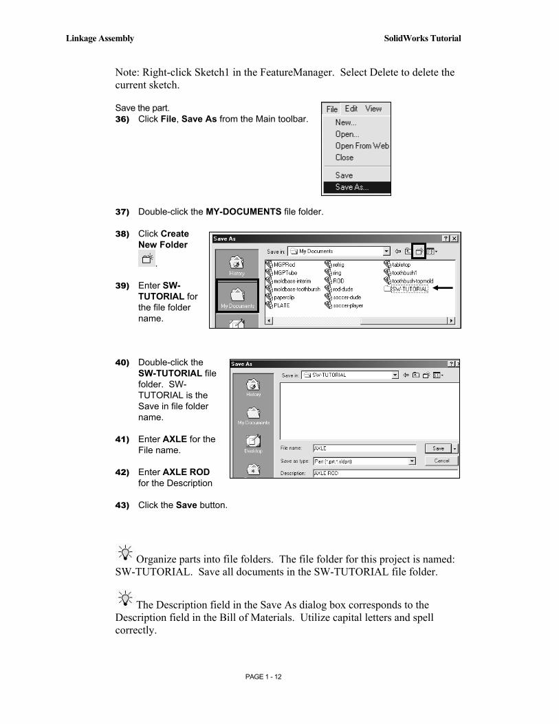
Note: Right-click Sketch1 in the FeatureManager. Select Delete to delete the current sketch.
Save the part. 36) Click File, Save As from the Main toolbar.
37) Double-click the MY-DOCUMENTS file folder.
38) Click Create New Folder
.
39) Enter SW-TUTORIAL for the file folder name.
40) Double-click the SW-TUTORIAL file folder. SW-TUTORIAL is the Save in file folder name.
41) Enter AXLE for the File name.
42) Enter AXLE ROD for the Description
43) Click the Save button.
Organize parts into file folders. The file folder for this project is named: SW-TUTORIAL. Save all documents in the SW-TUTORIAL file folder.
The Description field in the Save As dialog box corresponds to the Description field in the Bill of Materials. Utilize capital letters and spell correctly.
Copyrighted Material
Copyrighted
Material
Copyrighted Material
Copyrighted
Material
SolidWorks Tutorial Linkage Assembly
PAGE 1 - 13
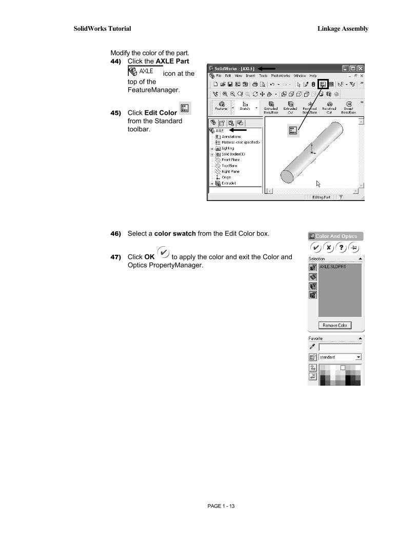
Modify the color of the part. 44) Click the AXLE Part
icon at the top of the FeatureManager.
45) Click Edit Color from the Standard toolbar.
46) Select a color swatch from the Edit Color box.
47) Click OK to apply the color and exit the Color and Optics PropertyManager.
Copyrighted Material
Copyrighted
Material
Copyrighted Material
Copyrighted
Material
Linkage Assembly SolidWorks Tutorial
PAGE 1 - 14
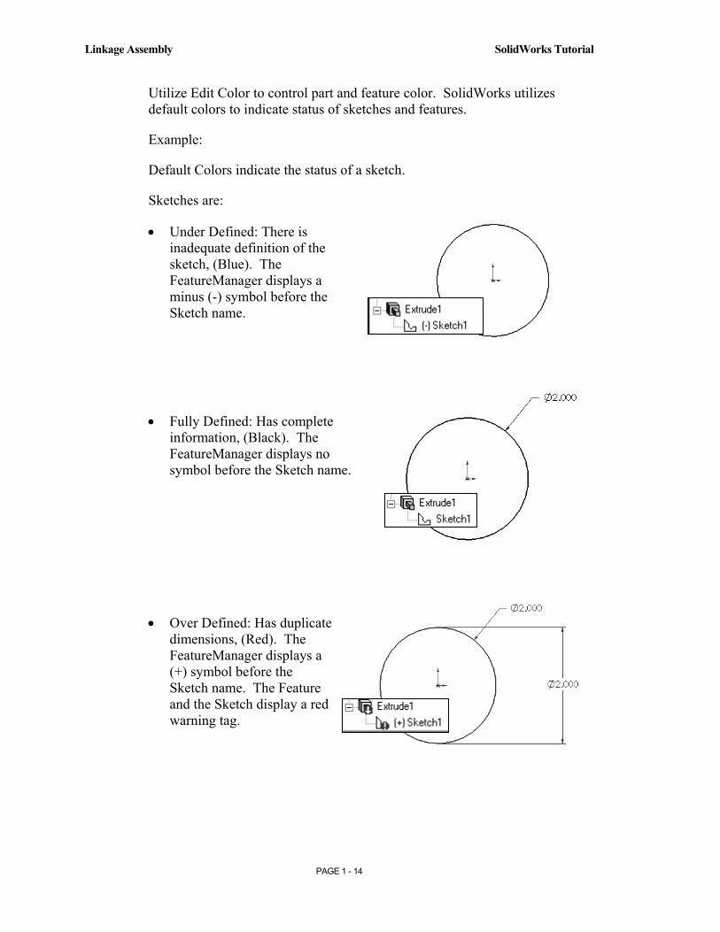
Utilize Edit Color to control part and feature color. SolidWorks utilizes default colors to indicate status of sketches and features.
Example:
Default Colors indicate the status of a sketch.
Sketches are:
• Under Defined: There is inadequate definition of the sketch, (Blue). The FeatureManager displays a minus (-) symbol before the Sketch name.
• Fully Defined: Has complete information, (Black). The FeatureManager displays no symbol before the Sketch name.
• Over Defined: Has duplicate dimensions, (Red). The FeatureManager displays a (+) symbol before the Sketch name. The Feature and the Sketch display a red warning tag.

Copyrighted Material
Copyrighted
Material
Copyrighted Material
Copyrighted
Material
SolidWorks Tutorial Linkage Assembly
PAGE 1 - 15
Display the Standard Views toolbar. 48) Click View from the Main menu.
49) Click Toolbars. The system places a Check Mark in the front of the displayed toolbars.
50) Click the Standard Views. The Standard Views toolbar is displayed below the Main menu.
51) Position the mouse pointer on an individual toolbar icon to receive a ToolTip.
Orthographic projection is the process of projecting views onto parallel planes with ⊥ projectors.
The default reference planes are the Front, Top and Right side viewing planes.
The Isometric view displays the part in 3D with two equal projection angles.
Copyrighted Material
Copyrighted
Material
Copyrighted Material
Copyrighted
Material
Linkage Assembly SolidWorks Tutorial
PAGE 1 - 16
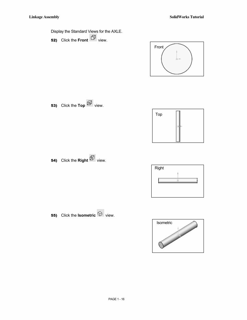
Display the Standard Views for the AXLE.
52) Click the Front view.
53) Click the Top view.
54) Click the Right view.
55) Click the Isometric view.
Front
Right
Isometric
Top
Copyrighted Material
Copyrighted
Material
Copyrighted Material
Copyrighted
Material
SolidWorks Tutorial Linkage Assembly
PAGE 1 - 17
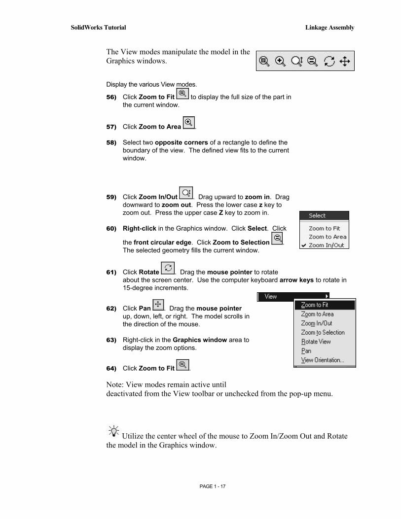
The View modes manipulate the model in the Graphics windows.
Display the various View modes.
56) Click Zoom to Fit to display the full size of the part in the current window.
57) Click Zoom to Area .
58) Select two opposite corners of a rectangle to define the boundary of the view. The defined view fits to the current window.
59) Click Zoom In/Out . Drag upward to zoom in. Drag downward to zoom out. Press the lower case z key to zoom out. Press the upper case Z key to zoom in.
60) Right-click in the Graphics window. Click Select. Click
the front circular edge. Click Zoom to Selection . The selected geometry fills the current window.
61) Click Rotate . Drag the mouse pointer to rotate about the screen center. Use the computer keyboard arrow keys to rotate in 15-degree increments.
62) Click Pan . Drag the mouse pointer up, down, left, or right. The model scrolls in the direction of the mouse.
63) Right-click in the Graphics window area to display the zoom options.
64) Click Zoom to Fit .
Note: View modes remain active until deactivated from the View toolbar or unchecked from the pop-up menu.
Utilize the center wheel of the mouse to Zoom In/Zoom Out and Rotate the model in the Graphics window.
Copyrighted Material
Copyrighted
Material
Copyrighted Material
Copyrighted
Material
Linkage Assembly SolidWorks Tutorial
PAGE 1 - 18
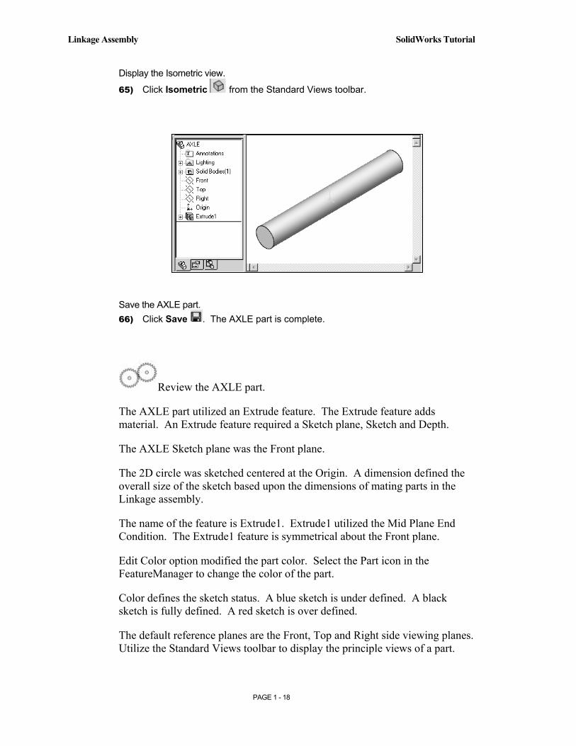
Display the Isometric view.
65) Click Isometric from the Standard Views toolbar.
Save the AXLE part. 66) Click Save . The AXLE part is complete.
Review the AXLE part.
The AXLE part utilized an Extrude feature. The Extrude feature adds material. An Extrude feature required a Sketch plane, Sketch and Depth.
The AXLE Sketch plane was the Front plane.
The 2D circle was sketched centered at the Origin. A dimension defined the overall size of the sketch based upon the dimensions of mating parts in the Linkage assembly.
The name of the feature is Extrude1. Extrude1 utilized the Mid Plane End Condition. The Extrude1 feature is symmetrical about the Front plane.
Edit Color option modified the part color. Select the Part icon in the FeatureManager to change the color of the part.
Color defines the sketch status. A blue sketch is under defined. A black sketch is fully defined. A red sketch is over defined.
The default reference planes are the Front, Top and Right side viewing planes. Utilize the Standard Views toolbar to display the principle views of a part.
Copyrighted Material
Copyrighted
Material
Copyrighted Material
Copyrighted
Material
SolidWorks Tutorial Linkage Assembly
PAGE 1 - 19
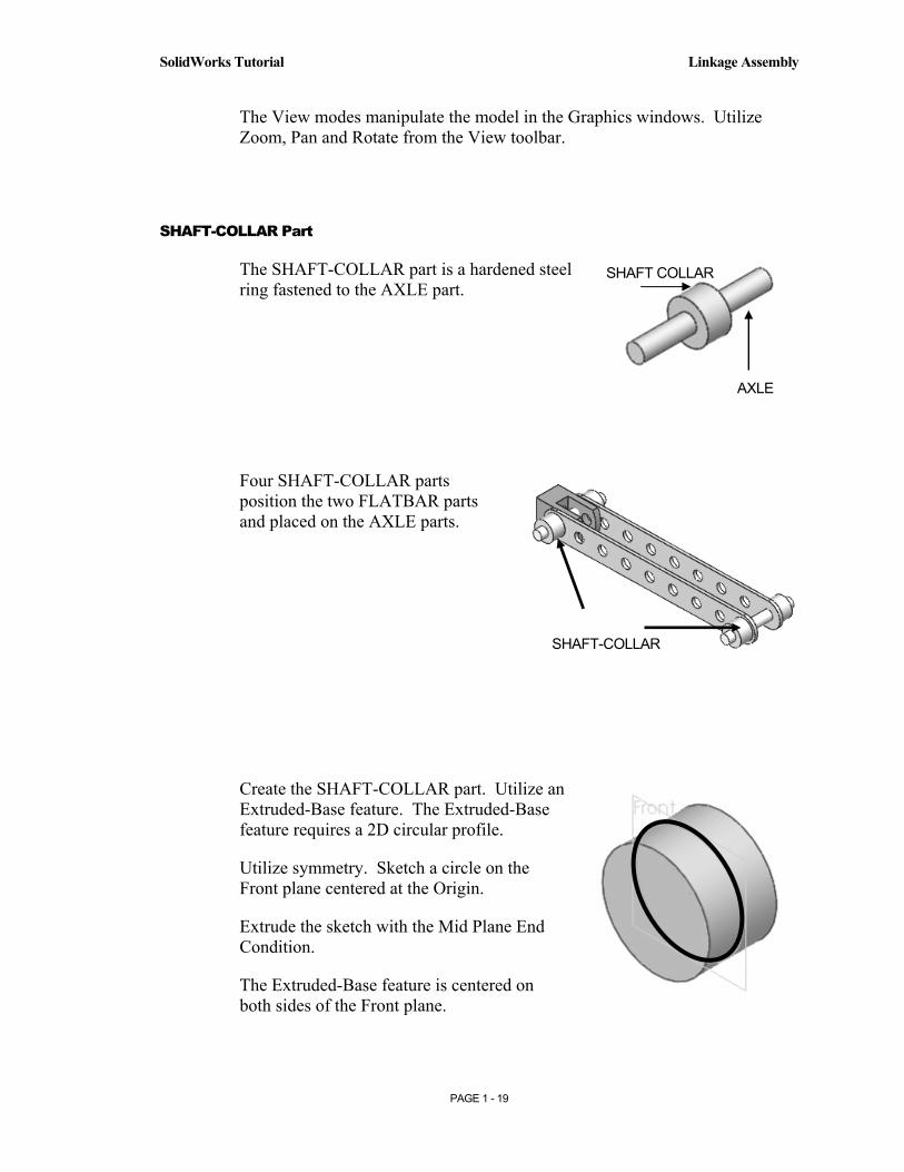
The View modes manipulate the model in the Graphics windows. Utilize Zoom, Pan and Rotate from the View toolbar.
SHAFT-COLLAR Part
The SHAFT-COLLAR part is a hardened steel ring fastened to the AXLE part.
Four SHAFT-COLLAR parts position the two FLATBAR parts and placed on the AXLE parts.
Create the SHAFT-COLLAR part. Utilize an Extruded-Base feature. The Extruded-Base feature requires a 2D circular profile.
Utilize symmetry. Sketch a circle on the Front plane centered at the Origin.
Extrude the sketch with the Mid Plane End Condition.
The Extruded-Base feature is centered on both sides of the Front plane.
SHAFT COLLAR
AXLE
SHAFT-COLLAR

Copyrighted Material
Copyrighted
Material
Copyrighted Material
Copyrighted
Material
Linkage Assembly SolidWorks Tutorial
PAGE 1 - 20
The Extruded-Cut feature removes material. Utilize an Extruded-Cut feature to create a hole.
The Extruded-Cut feature requires a 2D circular profile. Sketch a circle on the front face centered at the Origin.
Select the Depth option Through All extends the Extruded Cut feature from the Front plane through all existing geometry.
Create a New part. 67) Click New from the Standard toolbar.
68) The Templates tab is the default tab. Part is the default template from the New SolidWorks Document dialog box. Click OK.
69) Save the Part. Click File, Save As.
70) Select SW-TUTORIAL for the Save in file folder name.
71) Enter SHAFT-COLLAR for File name.
72) Enter SHAFT-COLLAR for Description.
73) Click the Save button.

Copyrighted Material
Copyrighted
Material
Copyrighted Material
Copyrighted
Material
SolidWorks Tutorial Linkage Assembly
PAGE 1 - 21
Set the dimensioning standard and part units. 74) Click Tools from the Main menu.
75) Click Options.
76) Click the Document Properties Tab.
77) Select ANSI from the Dimensioning Standard list box.
78) Click Units. Select IPS [MMGS] for Unit System.
79) Select 3 [2] for Length units Decimal places.
80) Select 0 [0] for Angular units Decimal places.
81) Click OK to set the document units.
Copyrighted Material
Copyrighted
Material
Copyrighted Material
Copyrighted
Material
Linkage Assembly SolidWorks Tutorial
PAGE 1 - 22
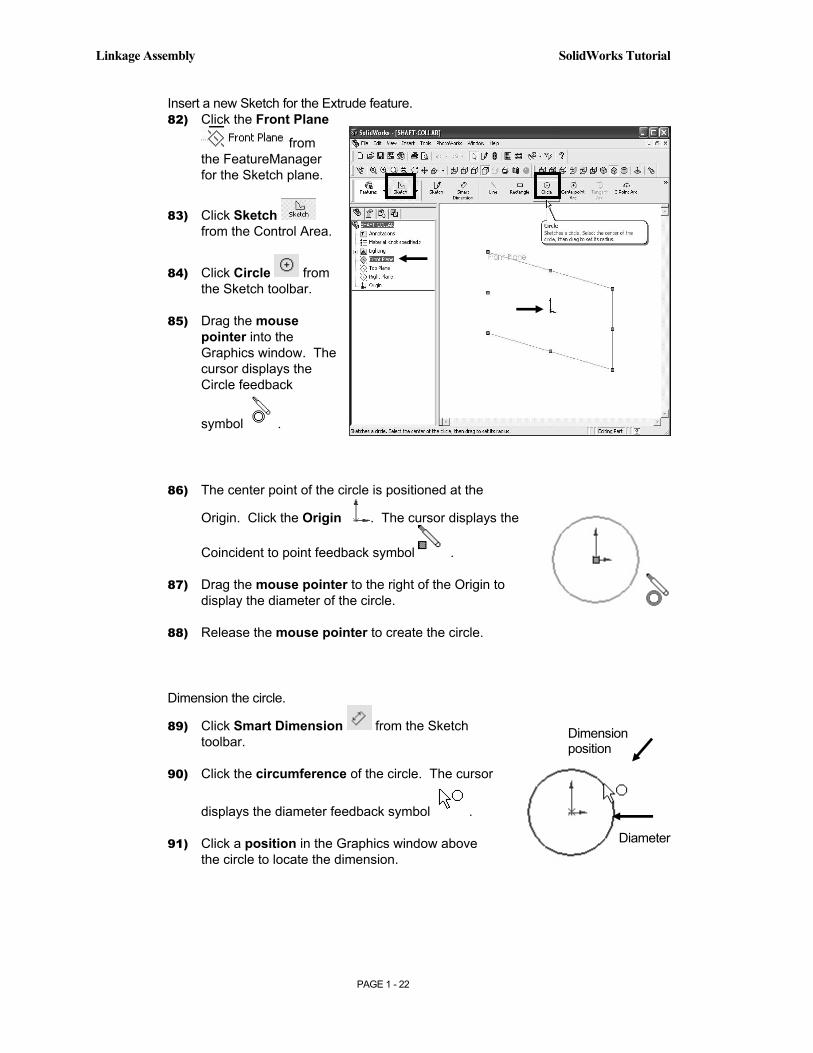
Insert a new Sketch for the Extrude feature. 82) Click the Front Plane
from the FeatureManager for the Sketch plane.
83) Click Sketch from the Control Area.
84) Click Circle from the Sketch toolbar.
85) Drag the mouse pointer into the Graphics window. The cursor displays the Circle feedback
symbol .
86) The center point of the circle is positioned at the
Origin. Click the Origin . The cursor displays the
Coincident to point feedback symbol .
87) Drag the mouse pointer to the right of the Origin to display the diameter of the circle.
88) Release the mouse pointer to create the circle.
Dimension the circle.
89) Click Smart Dimension from the Sketch toolbar.
90) Click the circumference of the circle. The cursor
displays the diameter feedback symbol .
91) Click a position in the Graphics window above the circle to locate the dimension.
Diameter
Dimension position

Copyrighted Material
Copyrighted
Material
Copyrighted Material
Copyrighted
Material
SolidWorks Tutorial Linkage Assembly
PAGE 1 - 23
92) Enter .4375 [11.11] in the Modify dialog box.
93) Click the Check Mark . The black sketch is fully defined.
Note: Three decimal places are displayed. The diameter value .4375 rounds to .438.
The Extrude Boss/Base icon is highlighted in the Features toolbar.
Extrude the sketch to create the first feature.
94) Click Features from the Control Area.
95) Click Extruded
Boss/Base from the Features toolbar.
96) Select Mid Plane for Direction1 End Condition.
97) Enter .250 [6.35] for Depth.
98) Click OK to create the Extruded-Base feature.
99) Fit the model to the Graphics window. Press the f key.
Copyrighted Material
Copyrighted
Material
Copyrighted Material
Copyrighted
Material
Linkage Assembly SolidWorks Tutorial
PAGE 1 - 24
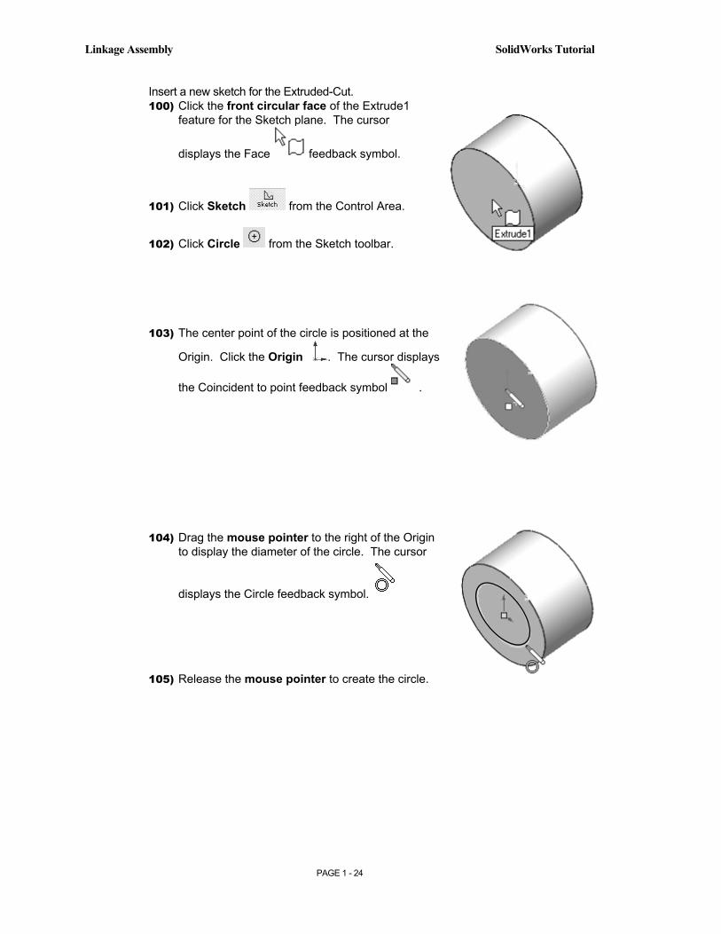
Insert a new sketch for the Extruded-Cut. 100) Click the front circular face of the Extrude1
feature for the Sketch plane. The cursor
displays the Face feedback symbol.
101) Click Sketch from the Control Area.
102) Click Circle from the Sketch toolbar.
103) The center point of the circle is positioned at the
Origin. Click the Origin . The cursor displays
the Coincident to point feedback symbol .
104) Drag the mouse pointer to the right of the Origin to display the diameter of the circle. The cursor
displays the Circle feedback symbol.
105) Release the mouse pointer to create the circle.

Copyrighted Material
Copyrighted
Material
Copyrighted Material
Copyrighted
Material
SolidWorks Tutorial Linkage Assembly
PAGE 1 - 25
Dimension the circle.
106) Click Smart Dimension from the Sketch toolbar.
107) Click the circumference of the circle. The cursor displays the diameter
feedback symbol .
108) Click a position in the Graphics window above the circle to locate the dimension.
109) Enter .1875 [4.76] in the Modify dialog box.
110) Click the Check Mark .
Insert an Extruded-Cut. 111) Click Features
from the Control Area.
112) Click Extruded-
Cut from the Features toolbar.
113) Select Through All for Direction1 End Condition.
114) Click OK to create the Extruded-Cut feature.
Copyrighted Material
Copyrighted
Material
Copyrighted Material
Copyrighted
Material
Linkage Assembly SolidWorks Tutorial
PAGE 1 - 26
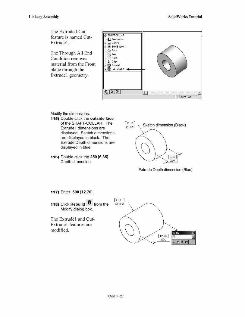
Sketch dimension (Black)
Extrude Depth dimension (Blue)
The Extruded-Cut feature is named Cut-Extrude1.
The Through All End Condition removes material from the Front plane through the Extrude1 geometry.
Modify the dimensions. 115) Double-click the outside face
of the SHAFT-COLLAR. The Extrude1 dimensions are displayed. Sketch dimensions are displayed in black. The Extrude Depth dimensions are displayed in blue.
116) Double-click the.250 [6.35] Depth dimension.
117) Enter .500 [12.70].
118) Click Rebuild from the Modify dialog box.
The Extrude1 and Cut-Extrude1 features are modified.
Copyrighted Material
Copyrighted
Material
Copyrighted Material
Copyrighted
Material
SolidWorks Tutorial Linkage Assembly
PAGE 1 - 27
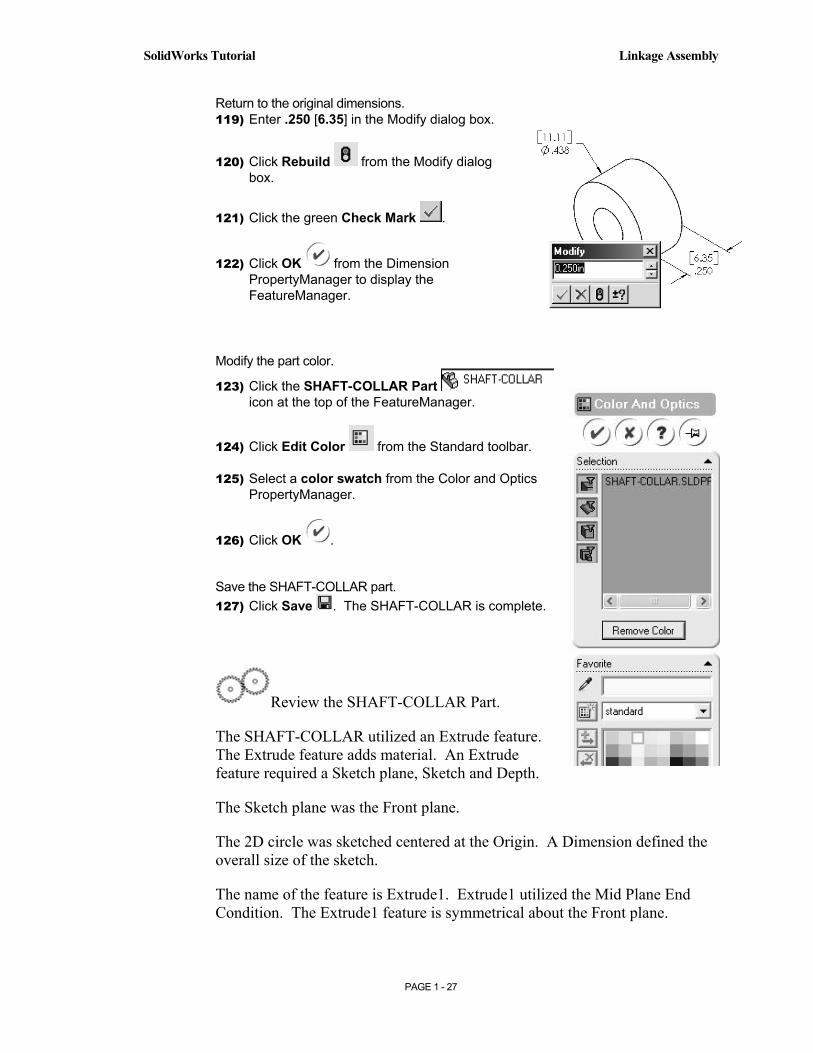
Return to the original dimensions. 119) Enter .250 [6.35] in the Modify dialog box.
120) Click Rebuild from the Modify dialog box.
121) Click the green Check Mark .
122) Click OK from the Dimension PropertyManager to display the FeatureManager.
Modify the part color.
123) Click the SHAFT-COLLAR Part icon at the top of the FeatureManager.
124) Click Edit Color from the Standard toolbar.
125) Select a color swatch from the Color and Optics PropertyManager.
126) Click OK .
Save the SHAFT-COLLAR part. 127) Click Save . The SHAFT-COLLAR is complete.
Review the SHAFT-COLLAR Part.
The SHAFT-COLLAR utilized an Extrude feature. The Extrude feature adds material. An Extrude feature required a Sketch plane, Sketch and Depth.
The Sketch plane was the Front plane.
The 2D circle was sketched centered at the Origin. A Dimension defined the overall size of the sketch.
The name of the feature is Extrude1. Extrude1 utilized the Mid Plane End Condition. The Extrude1 feature is symmetrical about the Front plane.
Copyrighted Material
Copyrighted
Material
Copyrighted Material
Copyrighted
Material
Linkage Assembly SolidWorks Tutorial
PAGE 1 - 28
The Extruded-Cut feature removed material to create the hole. The Extruded-Cut feature is named Cut-Extrude1.
The Through All End Condition option created the Cut-Extrude1 feature from the Front plane through all Extrude1 geometry.
Feature dimensions were changed. Modify feature dimension. Double-click the feature in the Graphics window. Double-click the dimension. Enter the new value. Rebuild the feature.
Edit Color option was utilized to modify the part color. Select the Part icon in the FeatureManager to modify the part color.
Additional details on Circle, Modify, Smart Dimensions, Sketch Color, Extruded Base and Extruded Cut are available in Online Help. Select Help, SolidWorks Help topics.
Keywords: Circle, Modify, Sketch (color), Dimension, Extrude.
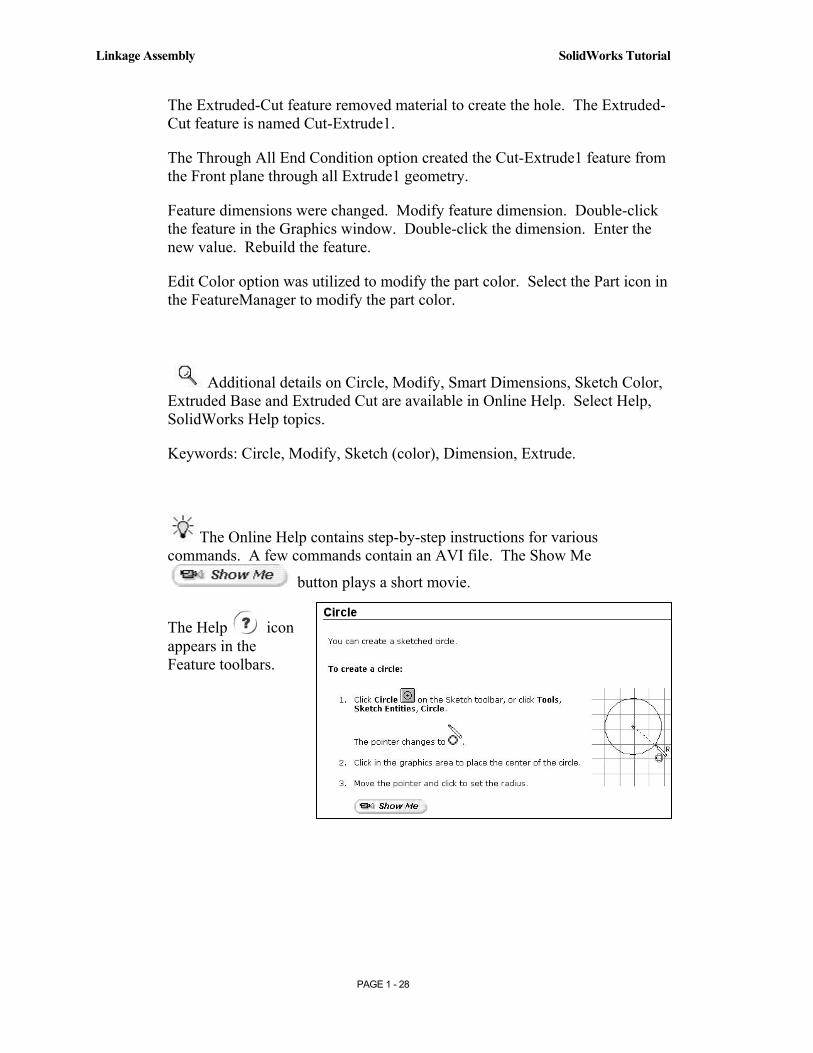
The Online Help contains step-by-step instructions for various commands. A few commands contain an AVI file. The Show Me
button plays a short movie.
The Help icon appears in the Feature toolbars.
Copyrighted Material
Copyrighted
Material
Copyrighted Material
Copyrighted
Material
SolidWorks Tutorial Linkage Assembly
PAGE 1 - 29
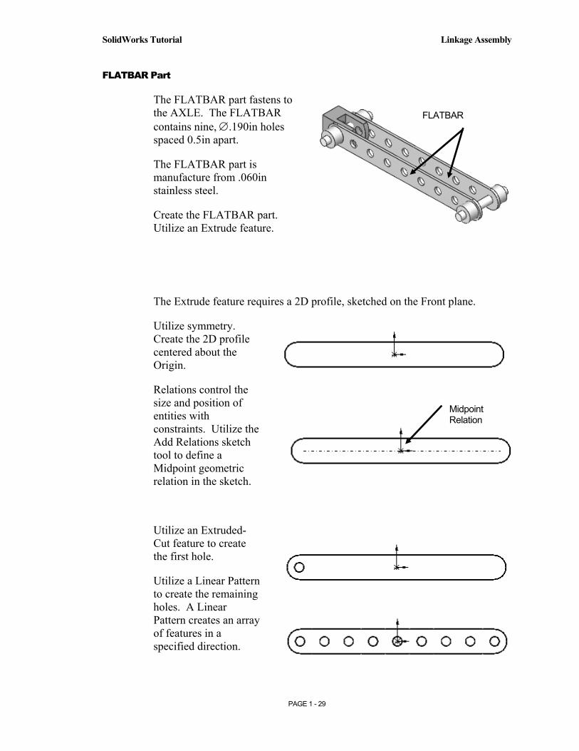
FLATBAR Part
The FLATBAR part fastens to the AXLE. The FLATBAR contains nine, ∅.190in holes spaced 0.5in apart.
The FLATBAR part is manufacture from .060in stainless steel.
Create the FLATBAR part. Utilize an Extrude feature.
The Extrude feature requires a 2D profile, sketched on the Front plane.
Utilize symmetry. Create the 2D profile centered about the Origin.
Relations control the size and position of entities with constraints. Utilize the Add Relations sketch tool to define a Midpoint geometric relation in the sketch.
Utilize an Extruded-Cut feature to create the first hole.
Utilize a Linear Pattern to create the remaining holes. A Linear Pattern creates an array of features in a specified direction.
FLATBAR
Midpoint Relation

Copyrighted Material
Copyrighted
Material
Copyrighted Material
Copyrighted
Material
Linkage Assembly SolidWorks Tutorial
PAGE 1 - 30
Create a New part. 128) Click New from the Standard toolbar.
129) The Templates tab is the default tab. Part is the default template from the New SolidWorks Document dialog box. Click OK.
Save the part. 130) Click File, Save As.
131) Select SW-TUTORIAL for the Save in folder file name.
132) Enter FLATBAR for File name.
133) Enter FLAT BAR 9 HOLES for Description.
134) Click the Save button.
Set the dimensioning standard and part units. 135) Click Tools from the Main menu.
136) Click Options.
137) Click the Document Properties Tab.
138) Select ANSI from the Dimensioning Standard list box.

Copyrighted Material
Copyrighted
Material
Copyrighted Material
Copyrighted
Material
SolidWorks Tutorial Linkage Assembly
PAGE 1 - 31
139) Click Units. Select IPS [MMGS] for Unit System.
140) Select 3 [2] for Length units Decimal places.
141) Select 0 [0] for Angular units Decimal places.
142) Click OK to set the document units.
Insert a new Sketch for the Extruded Base feature. 143) Click the Front
Plane
from the FeatureManager for the Sketch plane.
144) Click Sketch
from the Control Area.
145) Click Rectangle
from the Sketch toolbar.
Copyrighted Material
Copyrighted
Material
Copyrighted Material
Copyrighted
Material
Linkage Assembly SolidWorks Tutorial
PAGE 1 - 32
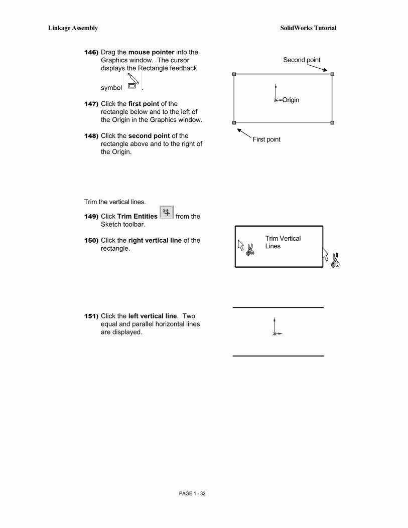
146) Drag the mouse pointer into the Graphics window. The cursor displays the Rectangle feedback
symbol .
147) Click the first point of the rectangle below and to the left of the Origin in the Graphics window.
148) Click the second point of the rectangle above and to the right of the Origin.
Trim the vertical lines.
149) Click Trim Entities from the Sketch toolbar.
150) Click the right vertical line of the rectangle.
151) Click the left vertical line. Two equal and parallel horizontal lines are displayed.
First point
Second point
Origin
Trim Vertical Lines

Copyrighted Material
Copyrighted
Material
Copyrighted Material
Copyrighted
Material
SolidWorks Tutorial Linkage Assembly
PAGE 1 - 33
Sketch the right Tangent Arc.
152) Click Tangent Arc from the Sketch toolbar.
153) Drag the mouse pointer along the top horizontal line to the right until a dotted horizontal line is displayed. The referenced top horizontal line is displayed in green.
154) Click the top right endpoint.
155) Drag the mouse pointer to the right and downward.
156) Click the bottom right endpoint. The cursor displays the
Coincident to point feedback symbol at each endpoint.
Sketch the left Tangent Arc. 157) Drag the mouse pointer along the top horizontal line to the
left until a dotted horizontal line is displayed.
158) Release the mouse pointer. The referenced top horizontal line is displayed in green.
159) Click the top left endpoint.
160) Drag the mouse pointer to the right and downward.
161) Click the bottom left endpoint. The cursor displays the
Coincident to point feedback symbol at each endpoint.
Copyrighted Material
Copyrighted
Material
Copyrighted Material
Copyrighted
Material
Linkage Assembly SolidWorks Tutorial
PAGE 1 - 34
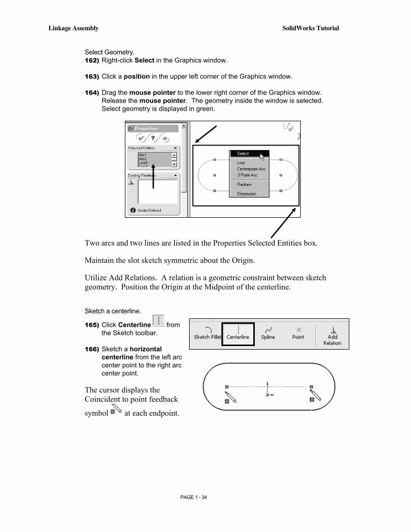
Select Geometry. 162) Right-click Select in the Graphics window.
163) Click a position in the upper left corner of the Graphics window.
164) Drag the mouse pointer to the lower right corner of the Graphics window. Release the mouse pointer. The geometry inside the window is selected. Select geometry is displayed in green.
Two arcs and two lines are listed in the Properties Selected Entities box.
Maintain the slot sketch symmetric about the Origin.
Utilize Add Relations. A relation is a geometric constraint between sketch geometry. Position the Origin at the Midpoint of the centerline.
Sketch a centerline.
165) Click Centerline from the Sketch toolbar.
166) Sketch a horizontal centerline from the left arc center point to the right arc center point.
The cursor displays the Coincident to point feedback
symbol at each endpoint.
Copyrighted Material
Copyrighted
Material
Copyrighted Material
Copyrighted
Material
SolidWorks Tutorial Linkage Assembly
PAGE 1 - 35
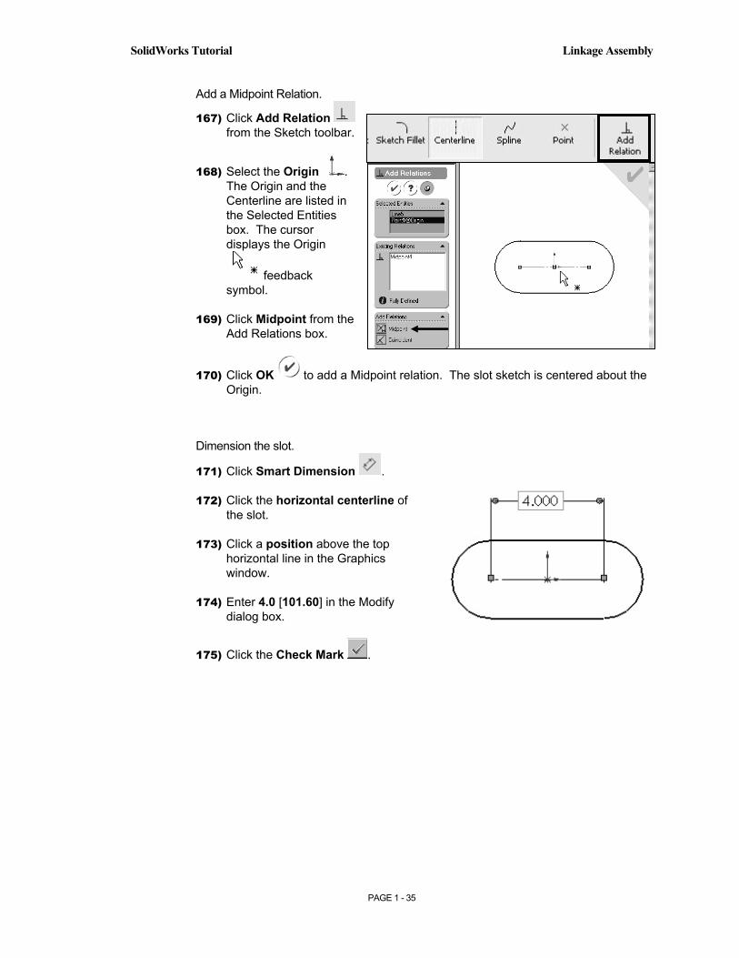
Add a Midpoint Relation.
167) Click Add Relation from the Sketch toolbar.
168) Select the Origin . The Origin and the Centerline are listed in the Selected Entities box. The cursor displays the Origin
feedback symbol.
169) Click Midpoint from the Add Relations box.
170) Click OK to add a Midpoint relation. The slot sketch is centered about the Origin.
Dimension the slot.
171) Click Smart Dimension .
172) Click the horizontal centerline of the slot.
173) Click a position above the top horizontal line in the Graphics window.
174) Enter 4.0 [101.60] in the Modify dialog box.
175) Click the Check Mark .

Copyrighted Material
Copyrighted
Material
Copyrighted Material
Copyrighted
Material
Linkage Assembly SolidWorks Tutorial
PAGE 1 - 36
176) Click the right arc of the slot.
177) Click a position to the right of the slot in the Graphics window to locate the dimension.
178) Enter .250 [6.35] in the Modify dialog box.
179) Click the Check Mark . The black sketch is fully defined.
Extrude the sketch to create the first feature.
180) Click Features from the Control Area.
181) Click Extruded
Boss/Base from the Features toolbar.
182) Enter .060 [1.5] for Depth.
183) Click OK to create the Extruded-Base feature.
184) Fit the model to the Graphics window. Press the f key.
Insert a new sketch for the Extruded-Cut. 185) Click the front slot face of the Extrude1 feature
for the Sketch plane. The cursor displays the
Face feedback symbol.

Copyrighted Material
Copyrighted
Material
Copyrighted Material
Copyrighted
Material
SolidWorks Tutorial Linkage Assembly
PAGE 1 - 37
186) Click Sketch
from the Control Area.
187) Display the Front view. Click the
Front view.
The process of placing the mouse pointer over an existing arc to find its center point is call “wake up”.
Wake up the center point.
188) Click Circle from the Sketch toolbar.
189) Place the mouse pointer on the left arc. Do not click. The center point of the slot arc is displayed.
190) Click the center point.
191) Click a position to the right of the center point to create the circle.
Copyrighted Material
Copyrighted
Material
Copyrighted Material
Copyrighted
Material
Linkage Assembly SolidWorks Tutorial
PAGE 1 - 38
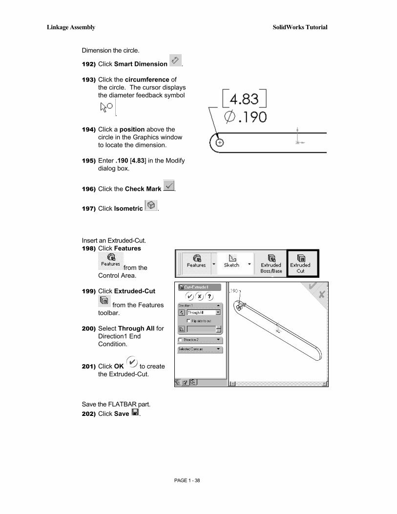
Dimension the circle.
192) Click Smart Dimension .
193) Click the circumference of the circle. The cursor displays the diameter feedback symbol
.
194) Click a position above the circle in the Graphics window to locate the dimension.
195) Enter .190 [4.83] in the Modify dialog box.
196) Click the Check Mark .
197) Click Isometric .
Insert an Extruded-Cut. 198) Click Features
from the Control Area.
199) Click Extruded-Cut
from the Features toolbar.
200) Select Through All for Direction1 End Condition.
201) Click OK to create the Extruded-Cut.
Save the FLATBAR part. 202) Click Save .
Copyrighted Material
Copyrighted
Material
Copyrighted Material
Copyrighted
Material
SolidWorks Tutorial Linkage Assembly
PAGE 1 - 39
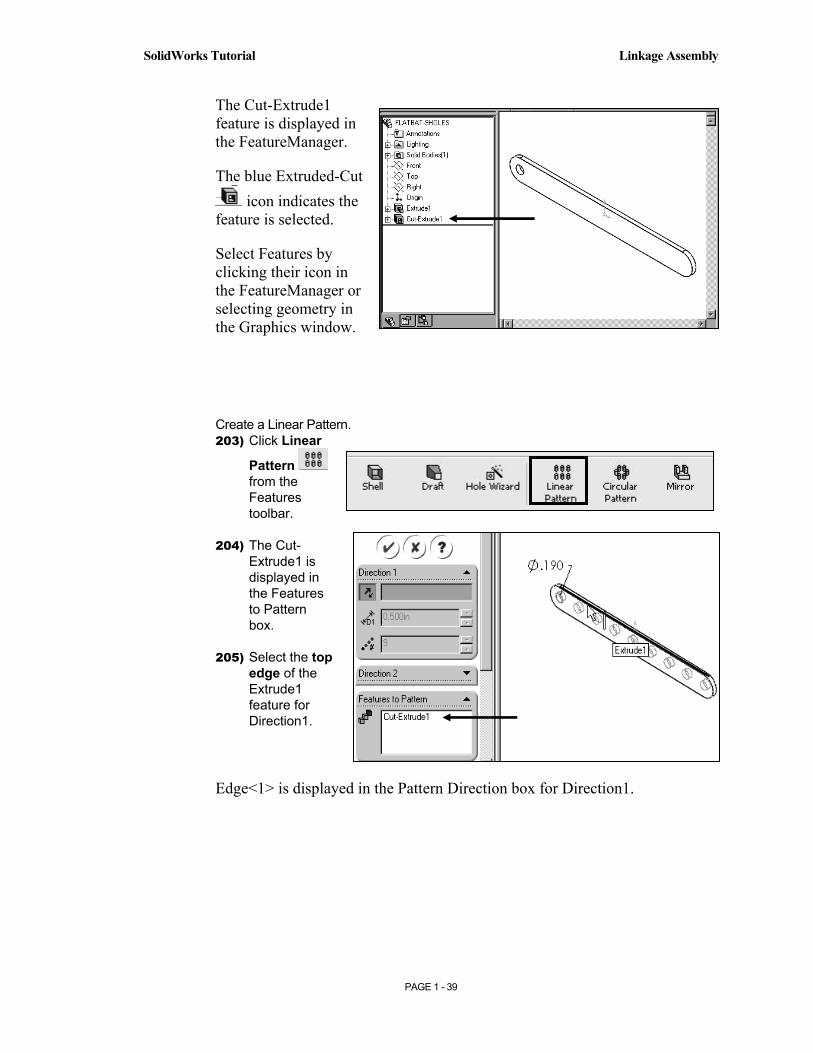
The Cut-Extrude1 feature is displayed in the FeatureManager.
The blue Extruded-Cut icon indicates the
feature is selected.
Select Features by clicking their icon in the FeatureManager or selecting geometry in the Graphics window.
Create a Linear Pattern. 203) Click Linear
Pattern from the Features toolbar.
204) The Cut-Extrude1 is displayed in the Features to Pattern box.
205) Select the top edge of the Extrude1 feature for Direction1.
Edge<1> is displayed in the Pattern Direction box for Direction1.

Copyrighted Material
Copyrighted
Material
Copyrighted Material
Copyrighted
Material
Linkage Assembly SolidWorks Tutorial
PAGE 1 - 40
206) Enter 0.5 [12.70] for Spacing.
207) Enter 9 for Number of Instances. Instances are the number of occurrences of a feature.
208) The Direction arrow points to the right. Click the Reverse Direction button if required.
209) Click OK to create the Linear Pattern.
The LPattern1 feature is listed in the FeatureManager.
Save the FLATBAR part. 210) Click Save . The FLATBAR part is complete.
Close all documents. 211) Click Windows from the Main toolbar.
212) Click Close All.
Pattern Direction
Copyrighted Material
Copyrighted
Material
Copyrighted Material
Copyrighted
Material
SolidWorks Tutorial Linkage Assembly
PAGE 1 - 41
Review the FLAT-BAR part.
The FLAT-BAR utilized an Extrude feature.
The Sketch plane was the Front plane.
The 2D sketch utilized the Rectangle and Tangent Arc Sketch tools to create the slot profile.
You created a Centerline between the two arc center points. The Midpoint relation maintained the slot profile symmetric about the Origin.
Linear and radial dimensions were added to define the overall size of the sketch.
The name of the feature is Extrude1. Extrude1 utilized the Blind End Condition.
The Extruded-Cut feature removed material to create the hole. The Extruded-Cut feature is named Cut-Extrude1.
The Through All End Condition option created the Cut-Extrude1 feature from the Front plane through all Extrude1 geometry.
The Linear Pattern created an array of 9 holes, equally spaced along the length of the FLATBAR.
Additional details on Rectangle, Trim Entities, Extruded Base, Extruded Boss, Extruded Cut and Linear Pattern are available in Online Help. Select Help, SolidWorks Help topics.
Keywords: Rectangle, Trim, Extrude, Features, Linear Pattern.
Additional information on Extruded features is available in Help, Introducing SolidWorks and Help, Online Tutorials.
Copyrighted Material
Copyrighted
Material
Copyrighted Material
Copyrighted
Material
Linkage Assembly SolidWorks Tutorial
PAGE 1 - 42
Linkage Assembly
An assembly is a document that contains two or more parts.
An assembly inserted into another assembly is called a sub-assembly.
A part or sub-assembly inserted into an assembly is called a component.
The LINKAGE assembly consists of the following components:
• AXLE part.
• SHAFT-COLLAR part.
• FLATBAR part.
• AirCylinder sub-assembly.
Establishing the correct component relationship in an assembly requires forethought on component interaction. Mates are geometric relationships that align and fit components in an assembly. Mates remove degrees of freedom from a component.
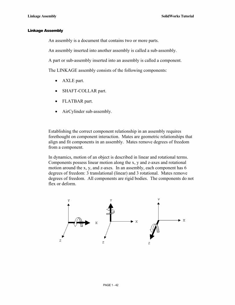
In dynamics, motion of an object is described in linear and rotational terms. Components possess linear motion along the x, y and z-axes and rotational motion around the x, y, and z-axes. In an assembly, each component has 6 degrees of freedom: 3 translational (linear) and 3 rotational. Mates remove degrees of freedom. All components are rigid bodies. The components do not flex or deform.
Copyrighted Material
Copyrighted
Material
Copyrighted Material
Copyrighted
Material
SolidWorks Tutorial Linkage Assembly
PAGE 1 - 43
Components are assembled with Standard Mate types. The Standard Mate types are Angle, Coincident, Concentric, Distance, Parallel, Perpendicular and Tangent.
The Advanced Mate types are Cam, Gear, Limit and Symmetric.
Mates require geometry from two different components.
Selected geometry includes Planar Faces, Cylindrical faces, Linear edges, Circular/Arc edges, Vertices, Axes, Temporary axes, Planes, Points and Origins.
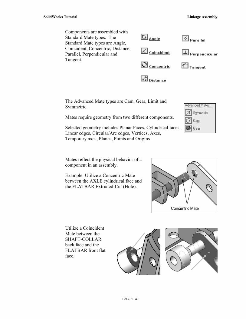
Mates reflect the physical behavior of a component in an assembly.
Example: Utilize a Concentric Mate between the AXLE cylindrical face and the FLATBAR Extruded-Cut (Hole).
Utilize a Coincident Mate between the SHAFT-COLLAR back face and the FLATBAR front flat face.
Concentric Mate
Copyrighted Material
Copyrighted
Material
Copyrighted Material
Copyrighted
Material
Linkage Assembly SolidWorks Tutorial
PAGE 1 - 44
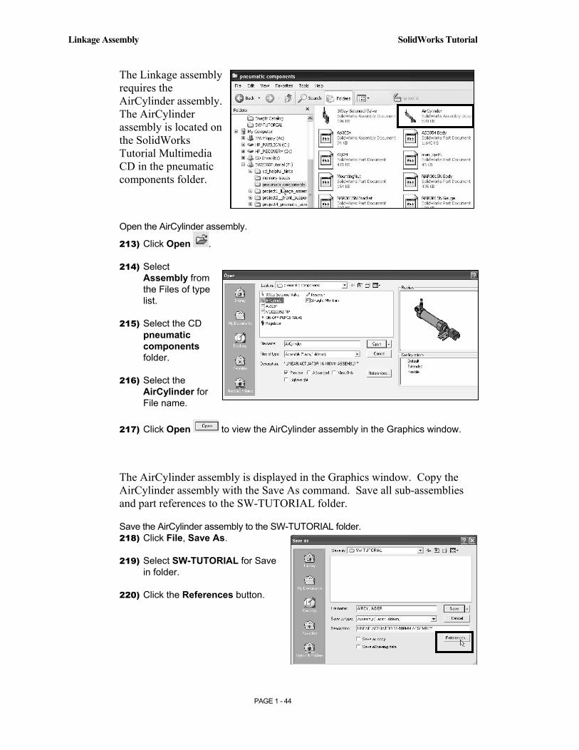
The Linkage assembly requires the AirCylinder assembly. The AirCylinder assembly is located on the SolidWorks Tutorial Multimedia CD in the pneumatic components folder.
Open the AirCylinder assembly.
213) Click Open .
214) Select Assembly from the Files of type list.
215) Select the CD pneumatic components folder.
216) Select the AirCylinder for File name.
217) Click Open to view the AirCylinder assembly in the Graphics window.
The AirCylinder assembly is displayed in the Graphics window. Copy the AirCylinder assembly with the Save As command. Save all sub-assemblies and part references to the SW-TUTORIAL folder.
Save the AirCylinder assembly to the SW-TUTORIAL folder. 218) Click File, Save As.
219) Select SW-TUTORIAL for Save in folder.
220) Click the References button.
Copyrighted Material
Copyrighted
Material
Copyrighted Material
Copyrighted
Material
SolidWorks Tutorial Linkage Assembly
PAGE 1 - 45
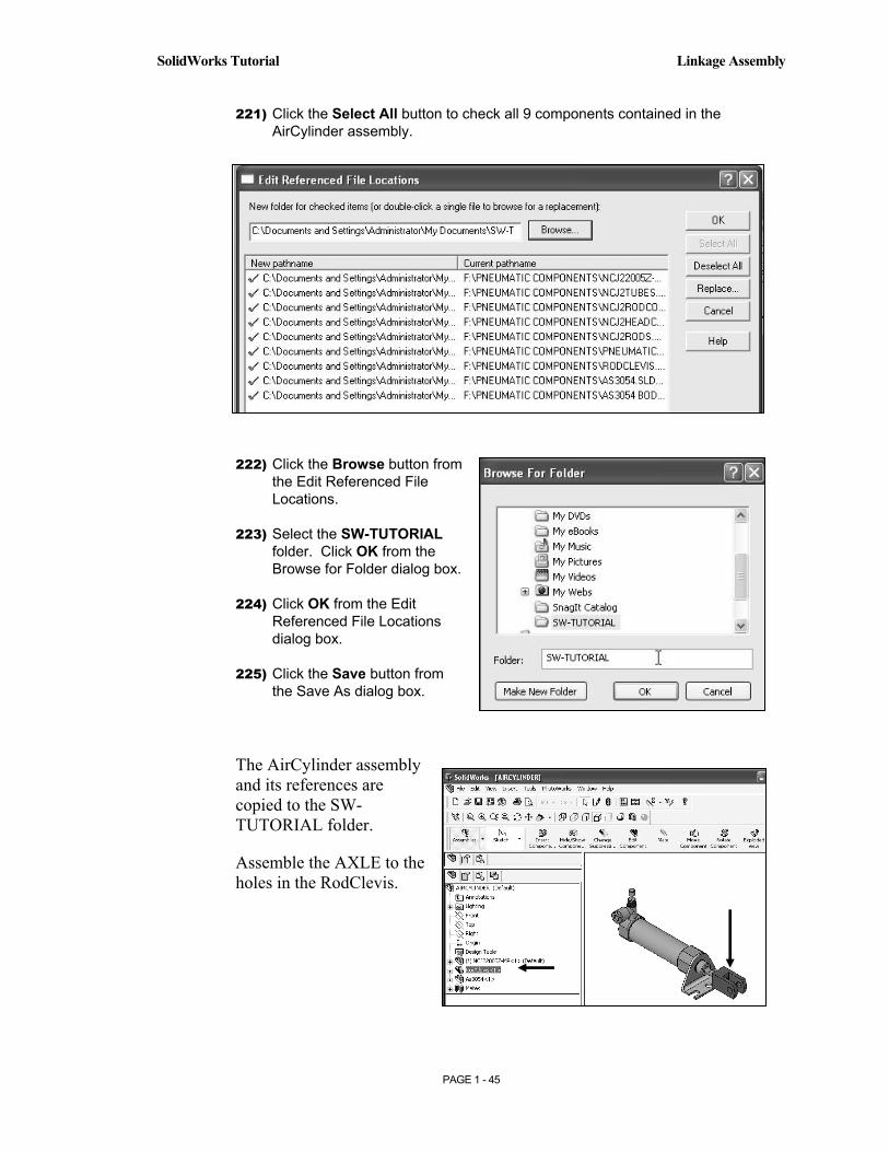
221) Click the Select All button to check all 9 components contained in the AirCylinder assembly.
222) Click the Browse button from the Edit Referenced File Locations.
223) Select the SW-TUTORIAL folder. Click OK from the Browse for Folder dialog box.
224) Click OK from the Edit Referenced File Locations dialog box.
225) Click the Save button from the Save As dialog box.
The AirCylinder assembly and its references are copied to the SW-TUTORIAL folder.
Assemble the AXLE to the holes in the RodClevis.
Copyrighted Material
Copyrighted
Material
Copyrighted Material
Copyrighted
Material
Linkage Assembly SolidWorks Tutorial
PAGE 1 - 46
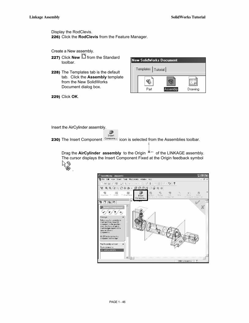
Display the RodClevis. 226) Click the RodClevis from the Feature Manager.
Create a New assembly. 227) Click New from the Standard
toolbar.
228) The Templates tab is the default tab. Click the Assembly template from the New SolidWorks Document dialog box.
229) Click OK.
Insert the AirCylinder assembly.
230) The Insert Component icon is selected from the Assemblies toolbar.
Drag the AirCylinder assembly to the Origin of the LINKAGE assembly. The cursor displays the Insert Component Fixed at the Origin feedback symbol
.
Copyrighted Material
Copyrighted
Material
Copyrighted Material
Copyrighted
Material
SolidWorks Tutorial Linkage Assembly
PAGE 1 - 47
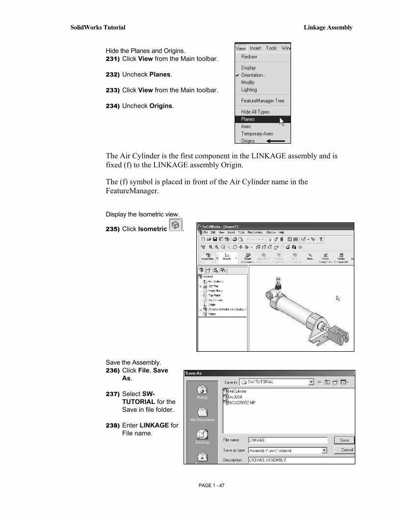
Hide the Planes and Origins. 231) Click View from the Main toolbar.
232) Uncheck Planes.
233) Click View from the Main toolbar.
234) Uncheck Origins.
The Air Cylinder is the first component in the LINKAGE assembly and is fixed (f) to the LINKAGE assembly Origin.
The (f) symbol is placed in front of the Air Cylinder name in the FeatureManager.
Display the Isometric view.
235) Click Isometric .
Save the Assembly. 236) Click File, Save
As.
237) Select SW-TUTORIAL for the Save in file folder.
238) Enter LINKAGE for File name.
Copyrighted Material
Copyrighted
Material
Copyrighted Material
Copyrighted
Material
Linkage Assembly SolidWorks Tutorial
PAGE 1 - 48
239) Enter LINKAGE ASSEMBLY for Description.
240) Click the Save button.
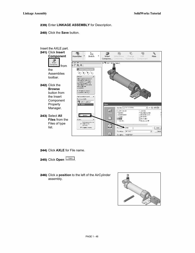
Insert the AXLE part. 241) Click Insert
Component
from the Assemblies toolbar.
242) Click the Browse button from the Insert Component Property Manager.
243) Select All Files from the Files of type list.
244) Click AXLE for File name.
245) Click Open .
246) Click a position to the left of the AirCylinder assembly.
Copyrighted Material
Copyrighted
Material
Copyrighted Material
Copyrighted
Material
SolidWorks Tutorial Linkage Assembly
PAGE 1 - 49
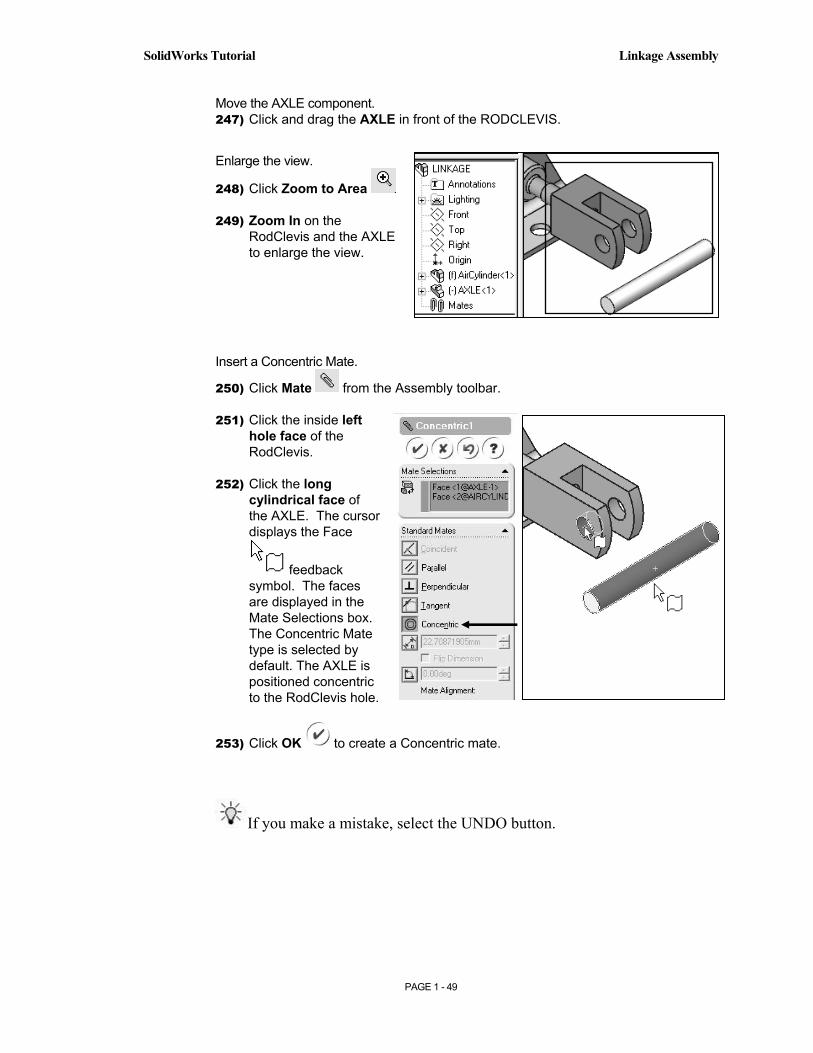
Move the AXLE component. 247) Click and drag the AXLE in front of the RODCLEVIS.
Enlarge the view.
248) Click Zoom to Area
249) Zoom In on the RodClevis and the AXLE to enlarge the view.
Insert a Concentric Mate.
250) Click Mate from the Assembly toolbar.
251) Click the inside left hole face of the RodClevis.
252) Click the long cylindrical face of the AXLE. The cursor displays the Face
feedback symbol. The faces are displayed in the Mate Selections box. The Concentric Mate type is selected by default. The AXLE is positioned concentric to the RodClevis hole.
253) Click OK to create a Concentric mate.
If you make a mistake, select the UNDO button.

Copyrighted Material
Copyrighted
Material
Copyrighted Material
Copyrighted
Material
Linkage Assembly SolidWorks Tutorial
PAGE 1 - 50
Move the AXLE. 254) Click and drag the AXLE left to
right. The AXLE translates in and out of the RodClevis holes.
255) Drag the AXLE vertically and horizontally. The AXLE rotates about its axis.
The Mate Pop-up toolbar is displayed after selecting the two cylindrical faces.
The Mate Pop-up toolbar minimizes the time required to create a Standard Mate.
Position the mouse pointer in the middle of the face, to select the entire face. Do not position the mouse pointer near the edge of the face. If the wrong face or edge is selected, perform one of the following actions:
• Click the face or edge again to remove it from the Items Selected text box.
• Right-click in the Graphics window. Click Clear Selections to remove all geometry from the Items Selected text box.
• Utilize the UNDO button to begin the Mate command again.
Copyrighted Material
Copyrighted
Material
Copyrighted Material
Copyrighted
Material
SolidWorks Tutorial Linkage Assembly
PAGE 1 - 51
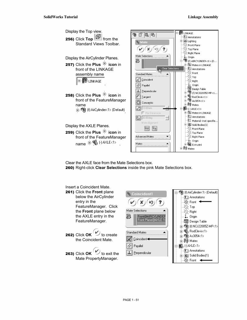
Display the Top view.
256) Click Top from the Standard Views Toolbar.
Display the AirCylinder Planes. 257) Click the Plus icon in
front of the LINKAGE assembly name
.
258) Click the Plus icon in front of the FeatureManager name
.
Display the AXLE Planes. 259) Click the Plus icon in
front of the FeatureManager
name .
Clear the AXLE face from the Mate Selections box. 260) Right-click Clear Selections inside the pink Mate Selections box.
Insert a Coincident Mate. 261) Click the Front plane
below the AirCylinder entry in the FeatureManager. Click the Front plane below the AXLE entry in the FeatureManager.
262) Click OK to create the Coincident Mate.
263) Click OK to exit the Mate PropertyManager.
Copyrighted Material
Copyrighted
Material
Copyrighted Material
Copyrighted
Material
Linkage Assembly SolidWorks Tutorial
PAGE 1 - 52
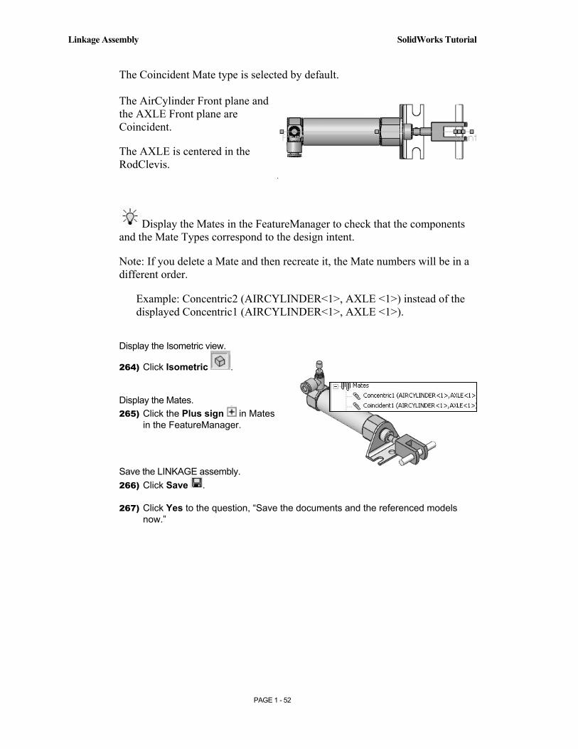
The Coincident Mate type is selected by default. The AirCylinder Front plane and the AXLE Front plane are Coincident.
The AXLE is centered in the RodClevis.
Display the Mates in the FeatureManager to check that the components and the Mate Types correspond to the design intent.
Note: If you delete a Mate and then recreate it, the Mate numbers will be in a different order.
Example: Concentric2 (AIRCYLINDER<1>, AXLE <1>) instead of the displayed Concentric1 (AIRCYLINDER<1>, AXLE <1>).
Display the Isometric view.
264) Click Isometric .
Display the Mates. 265) Click the Plus sign in Mates
in the FeatureManager.
Save the LINKAGE assembly. 266) Click Save .
267) Click Yes to the question, “Save the documents and the referenced models now.”
Copyrighted Material
Copyrighted
Material
Copyrighted Material
Copyrighted
Material
SolidWorks Tutorial Linkage Assembly
PAGE 1 - 53
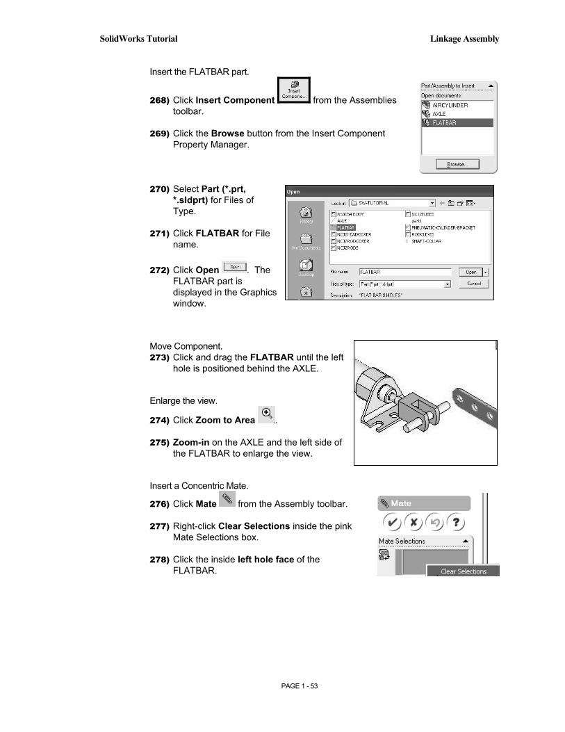
Insert the FLATBAR part.
268) Click Insert Component from the Assemblies toolbar.
269) Click the Browse button from the Insert Component Property Manager.
270) Select Part (*.prt, *.sldprt) for Files of Type.
271) Click FLATBAR for File name.
272) Click Open . The FLATBAR part is displayed in the Graphics window.
Move Component. 273) Click and drag the FLATBAR until the left
hole is positioned behind the AXLE.
Enlarge the view.
274) Click Zoom to Area .
275) Zoom-in on the AXLE and the left side of the FLATBAR to enlarge the view.
Insert a Concentric Mate.
276) Click Mate from the Assembly toolbar.
277) Right-click Clear Selections inside the pink Mate Selections box.
278) Click the inside left hole face of the FLATBAR.

Copyrighted Material
Copyrighted
Material
Copyrighted Material
Copyrighted
Material
Linkage Assembly SolidWorks Tutorial
PAGE 1 - 54
279) Click the long cylindrical face of the AXLE. The faces are displayed in the Mate Settings box. The Concentric Mate type is selected by default.
280) Click OK to create the Concentric Mate.
Move the FLATBAR. 281) Click and drag the FLATBAR.
The FLATBAR translates and rotates along the AXLE.
Insert a Coincident Mate. 282) Click the front face of the
FLATBAR.
283) Press the left arrow key 5 times to rotate the model.

Copyrighted Material
Copyrighted
Material
Copyrighted Material
Copyrighted
Material
SolidWorks Tutorial Linkage Assembly
PAGE 1 - 55
284) Click the back face of the RodClevis. The faces are displayed in the Mate Settings box. The Coincident Mate type is selected by default.
285) Click OK to create the Coincident Mate.
286) Click OK to exit the Mate PropertyManager.
Display the Isometric view.
287) Click Isometric .

Copyrighted Material
Copyrighted
Material
Copyrighted Material
Copyrighted
Material
Linkage Assembly SolidWorks Tutorial
PAGE 1 - 56
Insert the second FLATBAR.
288) Click Insert Component from the Assemblies toolbar.
289) Click the Browse button from the Insert Component Property Manager.
290) Select Part (*.prt, *.sldprt) for Files of Type.
291) Click FLATBAR for File name.
292) Click Open . The FLATBAR part is displayed in the Graphics window.
293) Click a position to the to the left of the AirCylinder.
Enlarge the view.
294) Click Zoom to Area
295) Zoom-in on the second FLATBAR and the AXLE.
Insert a Concentric Mate.
296) Click Mate from the Assembly toolbar.
297) Click the inside left hole face of the second FLATBAR.
298) Click the long cylindrical face of the AXLE. The faces are displayed in the Mate Selection box. The Concentric Mate type is selected by default.
299) Click OK to create the Concentric Mate.
Copyrighted Material
Copyrighted
Material
Copyrighted Material
Copyrighted
Material
SolidWorks Tutorial Linkage Assembly
PAGE 1 - 57
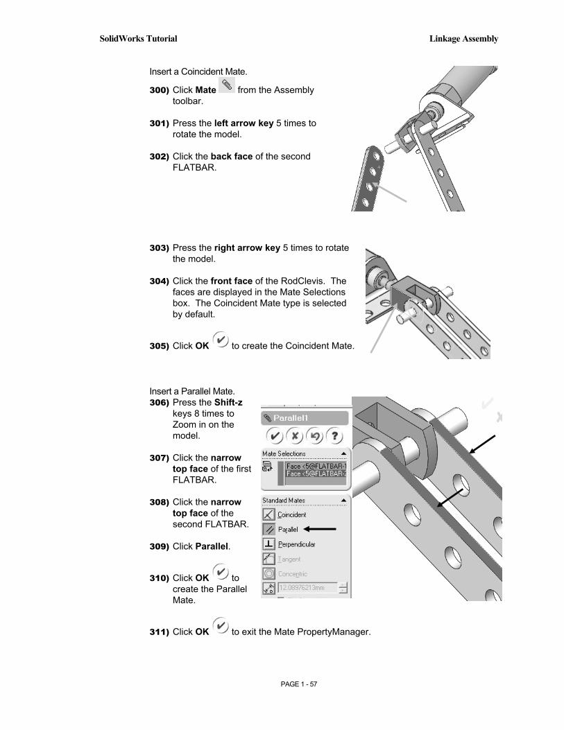
Insert a Coincident Mate.
300) Click Mate from the Assembly toolbar.
301) Press the left arrow key 5 times to rotate the model.
302) Click the back face of the second FLATBAR.
303) Press the right arrow key 5 times to rotate the model.
304) Click the front face of the RodClevis. The faces are displayed in the Mate Selections box. The Coincident Mate type is selected by default.
305) Click OK to create the Coincident Mate.
Insert a Parallel Mate. 306) Press the Shift-z
keys 8 times to Zoom in on the model.
307) Click the narrow top face of the first FLATBAR.
308) Click the narrow top face of the second FLATBAR.
309) Click Parallel.
310) Click OK to create the Parallel Mate.
311) Click OK to exit the Mate PropertyManager.
Copyrighted Material
Copyrighted
Material
Copyrighted Material
Copyrighted
Material
Linkage Assembly SolidWorks Tutorial
PAGE 1 - 58
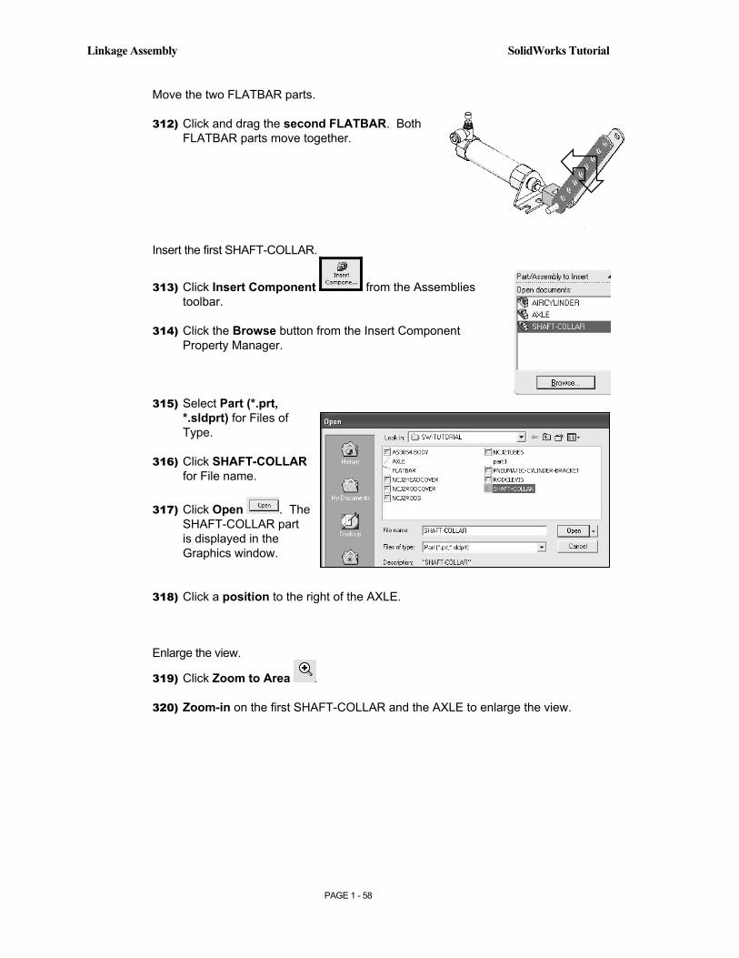
Move the two FLATBAR parts.
312) Click and drag the second FLATBAR. Both FLATBAR parts move together.
Insert the first SHAFT-COLLAR.
313) Click Insert Component from the Assemblies toolbar.
314) Click the Browse button from the Insert Component Property Manager.
315) Select Part (*.prt, *.sldprt) for Files of Type.
316) Click SHAFT-COLLAR for File name.
317) Click Open . The SHAFT-COLLAR part is displayed in the Graphics window.
318) Click a position to the right of the AXLE.
Enlarge the view.
319) Click Zoom to Area
320) Zoom-in on the first SHAFT-COLLAR and the AXLE to enlarge the view.
Copyrighted Material
Copyrighted
Material
Copyrighted Material
Copyrighted
Material
SolidWorks Tutorial Linkage Assembly
PAGE 1 - 59
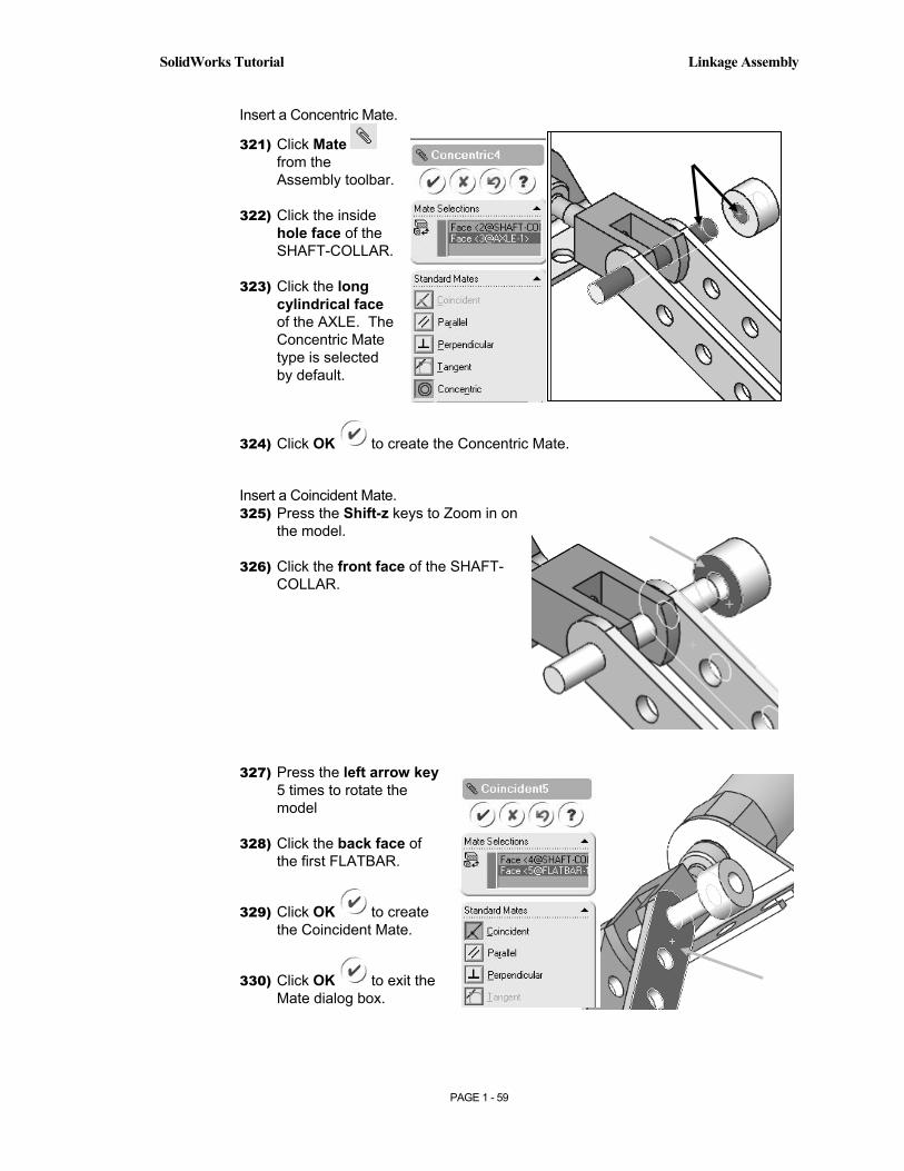
Insert a Concentric Mate.
321) Click Mate from the Assembly toolbar.
322) Click the inside hole face of the SHAFT-COLLAR.
323) Click the long cylindrical face of the AXLE. The Concentric Mate type is selected by default.
324) Click OK to create the Concentric Mate.
Insert a Coincident Mate. 325) Press the Shift-z keys to Zoom in on
the model.
326) Click the front face of the SHAFT-COLLAR.
327) Press the left arrow key 5 times to rotate the model
328) Click the back face of the first FLATBAR.
329) Click OK to create the Coincident Mate.
330) Click OK to exit the Mate dialog box.

Copyrighted Material
Copyrighted
Material
Copyrighted Material
Copyrighted
Material
Linkage Assembly SolidWorks Tutorial
PAGE 1 - 60
Display the Isometric view.
331) Click Isometric .
Insert the second SHAFT-COLLAR
332) Click Insert Component from the Assemblies toolbar.
333) Click the Browse button from the Insert Component Property Manager.
334) Select Part (*.prt, *.sldprt) for Files of Type.
335) Click SHAFT-COLLAR for File name.
336) Click Open . The SHAFT-COLLAR part is displayed in the Graphics window.
337) Click a position to the left of the AXLE.
Enlarge the view. 338) Click Zoom to Area
339) Zoom-in on the second SHAFT-COLLAR and the AXLE to enlarge the view.
Copyrighted Material
Copyrighted
Material
Copyrighted Material
Copyrighted
Material
SolidWorks Tutorial Linkage Assembly
PAGE 1 - 61
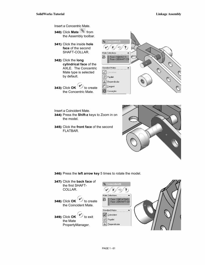
Insert a Concentric Mate.
340) Click Mate from the Assembly toolbar.
341) Click the inside hole face of the second SHAFT-COLLAR.
342) Click the long cylindrical face of the AXLE. The Concentric Mate type is selected by default.
343) Click OK to create the Concentric Mate.
Insert a Coincident Mate. 344) Press the Shift-z keys to Zoom in on
the model.
345) Click the front face of the second FLATBAR.
346) Press the left arrow key 5 times to rotate the model.
347) Click the back face of the first SHAFT-COLLAR.
348) Click OK to create the Coincident Mate.
349) Click OK to exit the Mate PropertyManager.
Copyrighted Material
Copyrighted
Material
Copyrighted Material
Copyrighted
Material
Linkage Assembly SolidWorks Tutorial
PAGE 1 - 62
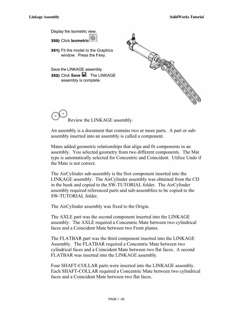
Display the Isometric view.
350) Click Isometric .
351) Fit the model to the Graphics window. Press the f key.
Save the LINKAGE assembly. 352) Click Save . The LINKAGE
assembly is complete.
Review the LINKAGE assembly.
An assembly is a document that contains two or more parts. A part or sub-assembly inserted into an assembly is called a component.
Mates added geometric relationships that align and fit components in an assembly. You selected geometry from two different components. The Mat type is automatically selected for Concentric and Coincident. Utilize Undo if the Mate is not correct.
The AirCylinder sub-assembly is the first component inserted into the LINKAGE assembly. The AirCylinder assembly was obtained from the CD in the book and copied to the SW-TUTORIAL folder. The AirCylinder assembly required referenced parts and sub-assemblies to be copied to the SW-TUTORIAL folder.
The AirCylinder assembly was fixed to the Origin.
The AXLE part was the second component inserted into the LINKAGE assembly. The AXLE required a Concentric Mate between two cylindrical faces and a Coincident Mate between two Front planes.
The FLATBAR part was the third component inserted into the LINKAGE Assembly. The FLATBAR required a Concentric Mate between two cylindrical faces and a Coincident Mate between two flat faces. A second FLATBAR was inserted into the LINKAGE assembly.
Four SHAFT-COLLAR parts were inserted into the LINKAGE assembly. Each SHAFT-COLLAR required a Concentric Mate between two cylindrical faces and a Coincident Mate between two flat faces.
Copyrighted Material
Copyrighted
Material
Copyrighted Material
Copyrighted
Material
SolidWorks Tutorial Linkage Assembly
PAGE 1 - 63
Physical Simulation Tools
The Physical Simulation tools represent the effects of motors, springs and gravity on an assembly. The Physical Simulation tools are combined with Mates and Physical Dynamics to translate and rotate components in an assembly.
The Simulation Toolbar contains four simulation tools: Linear Motor, Rotary Motor, Spring and Gravity.
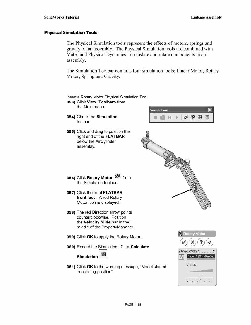
Insert a Rotary Motor Physical Simulation Tool. 353) Click View, Toolbars from
the Main menu.
354) Check the Simulation toolbar.
355) Click and drag to position the right end of the FLATBAR below the AirCylinder assembly.
356) Click Rotary Motor from the Simulation toolbar.
357) Click the front FLATBAR front face. A red Rotary Motor icon is displayed.
358) The red Direction arrow points counterclockwise. Position the Velocity Slide bar in the middle of the PropertyManager.
359) Click OK to apply the Rotary Motor.
360) Record the Simulation. Click Calculate
Simulation .
361) Click OK to the warning message, “Model started in colliding position”.

Copyrighted Material
Copyrighted
Material
Copyrighted Material
Copyrighted
Material
Linkage Assembly SolidWorks Tutorial
PAGE 1 - 64
The simulation continues and ignores the collisions. The FLATBAR rotates in a counterclockwise direction.
362) Stop the Simulation. Click Stop Simulation .
363) Return to the starting position. Click Reset Components .
364) Replay the Simulation. Click Replay .
365) Stop the Simulation. Click Stop Simulation .
366) Return to the starting position. Click Reset Components .
367) Fit the assembly to the Graphics window. Press the f key.
368) Save the LINKAGE assembly. Click Save .
369) Exit SolidWorks. Click File. Click Exit.
The LINKAGE assembly project is complete.
Linear Assembly Physical Simulation

Copyrighted Material
Copyrighted
Material
Copyrighted Material
Copyrighted
Material
SolidWorks Tutorial Linkage Assembly
PAGE 1 - 65
Review the Physical Simulation.
The Rotary Motor Physical Simulation tool combined Mates and Physical Dynamics to rotate the FLATBAR components in the LINKAGE assembly.
The Rotary Motor was applied to the front face of the FLATBAR.
You utilized Record to record the simulation and Play to view the simulation.
Additional details on Assembly, Mates and Simulation are available in Online Help. Select Help, SolidWorks Help topics.
Keywords: Standard Mates, Mate PropertyManager, Design Methods in Assembly, Physical Simulation.
Additional information on Assemblies is available in Help, Introducing SolidWorks and Help, Online Tutorials.
Review the Keyboard Short Cuts on page I-22 in the Introduction. Utilize the Keyboard Short Cuts to save modeling time.

Copyrighted Material
Copyrighted
Material
Copyrighted Material
Copyrighted
Material
Linkage Assembly SolidWorks Tutorial
PAGE 1 - 66
Project Summary
In this project you created three parts, downloaded the AirCylinder assembly and created the LINKAGE assembly.
You developed an understanding of the SolidWorks User Interface: Menus, Toolbars, System feedback, Keyboard shortcuts, Document Properties, Templates, Parts and Assemblies.
You obtained the knowledge of the following SolidWorks features: Extruded-Base, Extruded-Cut and Linear Pattern.
Features are the building blocks of parts. The Extrude feature required a sketch plane, sketch and depth.
The Extruded-Base feature added material to a part. The Extruded-Base feature was utilized in the AXLE, SHAFT-COLLAR and FLATBAR parts.
The Extruded-Cut removed material from the part. The Extruded-Cut feature was utilized to create a hole in the SHAFT-COLLAR and FLATBAR parts.
The Linear Pattern feature was utilized to create an array of holes in the FLATBAR part.
When parts are inserted into an assembly, they are called components. You created the LINKAGE assembly by inserting the AirCylinder assembly, AXLE, SHAFT-COLLAR and FLATBAR parts.
Mates are geometric relationships that align and fit components in an assembly. Concentric, Coincident and Parallel Mates were utilized to assemble the components.
The Rotary Motor Physical Simulation tool combined Mates and Physical Dynamics to rotate the FLATBAR components in the LINKAGE assembly.
Copyrighted Material
Copyrighted
Material
Copyrighted Material
Copyrighted
Material
SolidWorks Tutorial Linkage Assembly
PAGE 1 - 67
Project Terminology
Utilize Online Help for additional information about the terms utilized in this project.
Units: Used in the measurement of physical quantities. Millimeter dimensioning and decimal inch dimensioning are the two types of common units specified for engineering parts and drawings.
Dimensioning Standard: A set of drawing and detailing options developed by national and international organizations. The Dimensioning standard options are: ANSI, ISO, DIN, JIS, BSI, GOST and GB.
Part: A part is a single 3D object made up of features. The filename extension for a SolidWorks part file name is .SLDPRT.
Assembly: An assembly is a document in which parts, features, and other assemblies (sub-assemblies). When a part is inserted into an assembly it is called a component. Components are mated together. The filename extension for a SolidWorks assembly file name is .SLDASM.
Features: Features are geometry building blocks. Features add or remove material. Features are created from sketched profiles or from edges and faces of existing geometry.
Sketch: The name to describe a 2D profile is called a sketch. 2D Sketches are created on flat faces and planes within the model. Typical geometry types are lines, arcs, rectangles, circles, polygons and ellipses.
Status of a Sketch: Three states are utilized in this Project:
• Under Defined: There is inadequate definition of the sketch, (Blue).
• Fully Defined: Has complete information, (Black).
• Over Defined: Has duplicate dimensions, (Red).
Plane: To create a sketch, choose a plane. Planes are flat and infinite. They are represented on the screen with visible edges. The reference plane for this project is the Front Plane.
Relation: A relation is a geometric constraint between sketch entities or between a sketch entity and a plane, axis, edge, or vertex. Utilize Add Relations to manually connect related geometry.
Dimension: A value indicating the size of feature geometry.
Copyrighted Material
Copyrighted
Material
Copyrighted Material
Copyrighted
Material
Linkage Assembly SolidWorks Tutorial
PAGE 1 - 68
Trim Entities: Deletes selected sketched geometry. Extends a sketch segment unit it is coincident with another entity.
Component: A part or sub-assembly within an assembly.
Mates: A Mate is a geometric relationship between components in an assembly.
Menus: Menus provide access to the commands that the SolidWorks software offers.
Toolbars: The toolbar menus provide shortcuts enabling you to quickly access the most frequently used commands.
Mouse Buttons: The left and right mouse buttons have distinct meanings in SolidWorks. Left mouse button is utilized to select geometry. Right-mouse button is utilized to invoke commands.
Cursor Feedback: Feedback is provided by a symbol attached to the cursor arrow indicating your selection. As the cursor floats across the model, feedback is provided in the form of symbols, riding next to the cursor.
Project Features:
View the Multimedia CD for additional examples of the features utilized in this project.
Extruded-Base/Boss: Use to add material by extrusions. The Extruded is the first feature in a part. An Extruded Boss occurs after the first feature.
Steps to create an Extruded-Base/Boss:
• Select the Sketch plane.
• Sketch the profile.
• Add Dimensions and Relations.
• Select the Extrude Boss/Base from the Features toolbar.
• Enter Depth, select end conditions and or options.

Copyrighted Material
Copyrighted
Material
Copyrighted Material
Copyrighted
Material
SolidWorks Tutorial Linkage Assembly
PAGE 1 - 69
Extruded-Cut: Use to remove material from a solid. This is the opposite of the boss. Cuts begin as a 2D sketch and remove materials by extrusions.
Steps to create an Extruded-Cut:
• Select the Sketch plane.
• Sketch the profile.
• Add Dimensions and Relations.
• Select Extrude Cut from the Features toolbar.
• Enter Depth, select end conditions and or options.
Linear Pattern: A Linear Pattern repeats features or geometry in an array. A Linear Patten requires the number of instances and the spacing between instances.
Steps to create a Linear Pattern:
• Select the features to repeat.
• Select Linear Pattern from the Feature toolbar.
• Enter Direction of the pattern.
• Enter Number of pattern instances in each direction.
• Enter Distance between pattern instances.
• Optional: Pattern instances to skip.
Copyrighted Material
Copyrighted
Material
Copyrighted Material
Copyrighted
Material
Linkage Assembly SolidWorks Tutorial
PAGE 1 - 70
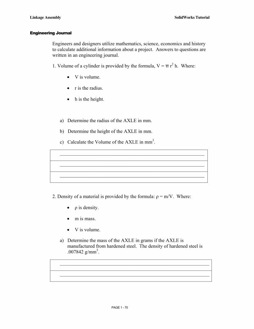
Engineering Journal
Engineers and designers utilize mathematics, science, economics and history to calculate additional information about a project. Answers to questions are written in an engineering journal.
1. Volume of a cylinder is provided by the formula, V = π r2 h. Where:
• V is volume.
• r is the radius.
• h is the height.
a) Determine the radius of the AXLE in mm.
b) Determine the height of the AXLE in mm.
c) Calculate the Volume of the AXLE in mm3.
__________________________________________________________
__________________________________________________________
__________________________________________________________
2. Density of a material is provided by the formula: ρ = m/V. Where:
• ρ is density.
• m is mass.
• V is volume.
a) Determine the mass of the AXLE in grams if the AXLE is manufactured from hardened steel. The density of hardened steel is .007842 g/mm3.
____________________________________________________________
____________________________________________________________

Copyrighted Material
Copyrighted
Material
Copyrighted Material
Copyrighted
Material
SolidWorks Tutorial Linkage Assembly
PAGE 1 - 71
3. The material supplier catalog lists Harden Steel Rod in foot lengths.
Harden Steel Rod (ø 3/16):
Part Number: Length: Cost:
23-123-1 1 ft $10.00
23-123-2 2 ft $18.00
23-123-3 3ft $24.00
Utilize the table above to determine the following questions:
a) How many 1-3/8 inch AXLES can be cut from each steel rod?
b) Twenty AXLE parts are required for a new assembly. What length of Harden Steel Rod should be purchased?
__________________________________________________________
__________________________________________________________
__________________________________________________________
__________________________________________________________
__________________________________________________________
__________________________________________________________
__________________________________________________________
__________________________________________________________
__________________________________________________________
Copyrighted Material
Copyrighted
Material
Copyrighted Material
Copyrighted
Material
Linkage Assembly SolidWorks Tutorial
PAGE 1 - 72
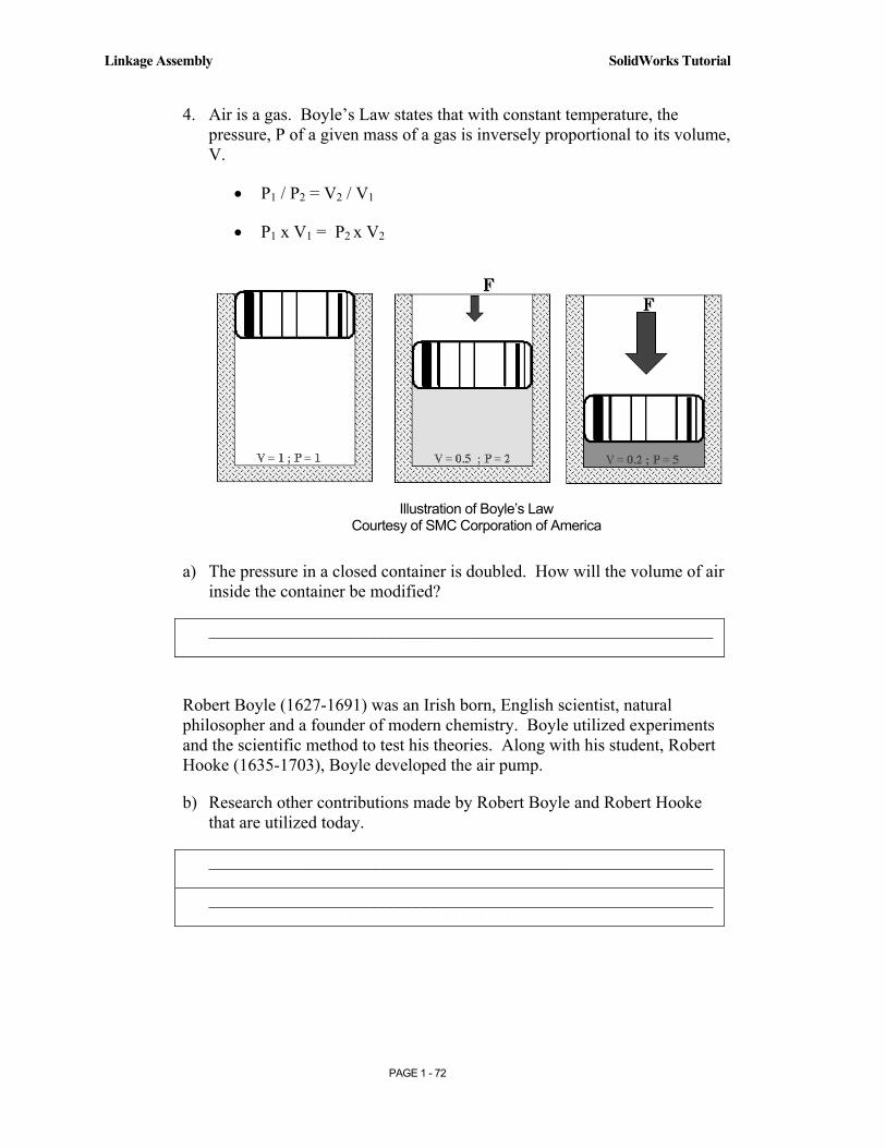
4. Air is a gas. Boyle’s Law states that with constant temperature, the pressure, P of a given mass of a gas is inversely proportional to its volume, V.
• P1 / P2 = V2 / V1
• P1 x V1 = P2 x V2
a) The pressure in a closed container is doubled. How will the volume of air inside the container be modified?
__________________________________________________________
Robert Boyle (1627-1691) was an Irish born, English scientist, natural philosopher and a founder of modern chemistry. Boyle utilized experiments and the scientific method to test his theories. Along with his student, Robert Hooke (1635-1703), Boyle developed the air pump.
b) Research other contributions made by Robert Boyle and Robert Hooke that are utilized today.
__________________________________________________________
__________________________________________________________
Illustration of Boyle’s Law Courtesy of SMC Corporation of America
Copyrighted Material
Copyrighted
Material
Copyrighted Material
Copyrighted
Material
SolidWorks Tutorial Linkage Assembly
PAGE 1 - 73
Questions
1. Explain the steps in starting a SolidWorks session.
2. Describe the procedure to begin a new sketch.
3. Explain the steps required to change part unit dimensions from inches to millimeters.
4. Describe a part.
5. Identify the three default reference planes.
6. What is the Base feature? Provide an example.
7. Describe the differences between an Extruded-Base feature and an Extruded-Cut feature.
8. The sketch color, black indicates a sketch is ___________ defined.
9. The sketch color, blue indicates a sketch is ___________ defined.
10. The sketch color, red indicates a sketch is ___________ defined.
11. Describe the procedure to “wake up” a centerpoint.
12. Define a relation. Provide an example.
13. What is a Linear Pattern? Provide an example.
14. Describe an assembly or sub-assembly.
15. What are Mates and why are they important in assembling components?
16. Describe Dynamic motion.
17. In an assembly, each component has_______# degrees of freedom? Name them.
18. True or False. A fixed component cannot move in an assembly.
19. Review the Design Intent section in the Introduction on page I-10. Identify how you incorporated design intent into the parts and assembly.
Copyrighted Material
Copyrighted
Material
Copyrighted Material
Copyrighted
Material
Linkage Assembly SolidWorks Tutorial
PAGE 1 - 74
Exercises
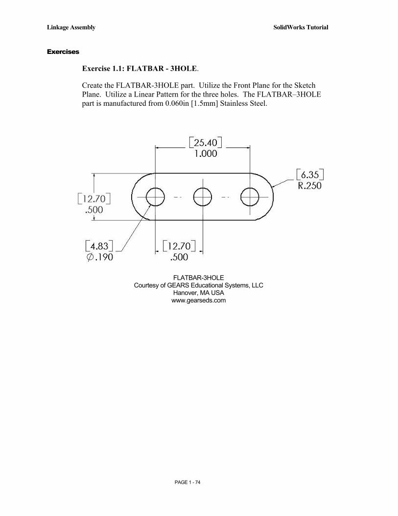
Exercise 1.1: FLATBAR - 3HOLE.
Create the FLATBAR-3HOLE part. Utilize the Front Plane for the Sketch Plane. Utilize a Linear Pattern for the three holes. The FLATBAR–3HOLE part is manufactured from 0.060in [1.5mm] Stainless Steel.
FLATBAR-3HOLE Courtesy of GEARS Educational Systems, LLC
Hanover, MA USA www.gearseds.com

Copyrighted Material
Copyrighted
Material
Copyrighted Material
Copyrighted
Material
SolidWorks Tutorial Linkage Assembly
PAGE 1 - 75
Exercise 1.2: FLATBAR-5HOLE.
Design the FLATBAR-5HOLE part.
Manually add dimensions to the 2D profile.
The dimensions for hole spacing, height and end arcs are the same as the FLATBAR-3HOLE part in Exercise 1.1.
Create the part. Utilize the Front Plane for the Sketch Plane. Utilize the Linear Pattern feature to create the hole pattern.
The FLATBAR–5HOLE part is manufactured from 0.060in [1.5mm] Stainless Steel.
FLATBAR-5HOLE Courtesy of GEARS Educational Systems, LLC
Hanover, MA USA www.gearseds.com

Copyrighted Material
Copyrighted
Material
Copyrighted Material
Copyrighted
Material
Linkage Assembly SolidWorks Tutorial
PAGE 1 - 76
Exercise 1.3a: LINKAGE-2 assembly.
Create the LINKAGE-2 assembly.
Open the LINKAGE assembly.
Select File, Save As from the Main menu.
Check the Save a Copy check box.
Enter LINKAGE-2 for file name.
The FLATBAR-3HOLE parts were created in Exercise 1.1.
Utilize 2 AXLE parts, 4 SHAFT COLLAR parts and 2 FLATBAR-3HOLE parts.
Linkage2 Assembly
Courtesy of Gears Educational Systems and
SMC Corporation of America.
Air Cylinder
SHAFT COLLAR
AXLE
FLATBAR
FLATBAR – 3HOLE

Copyrighted Material
Copyrighted
Material
Copyrighted Material
Copyrighted
Material
SolidWorks Tutorial Linkage Assembly
PAGE 1 - 77
Exercise 1.3b: LINKAGE-2 Assembly Simulation.
Create the LINKAGE-2 Assembly simulation
Apply a Rotary Motor to the front FLATBAR-3HOLE.
Record the Simulation.
Play the Simulation.
.
LINKAGE-2 Assembly Simulations
Collision
Copyrighted Material
Copyrighted
Material
Copyrighted Material
Copyrighted
Material
Linkage Assembly SolidWorks Tutorial
PAGE 1 - 78
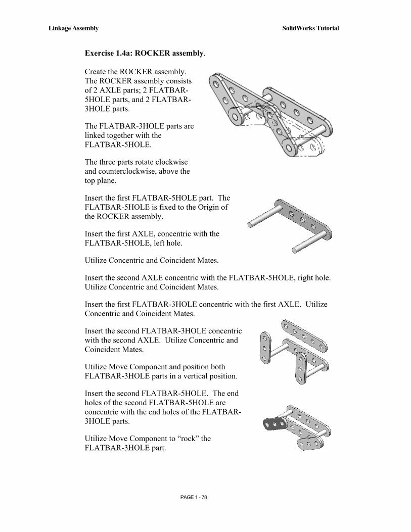
Exercise 1.4a: ROCKER assembly. Create the ROCKER assembly. The ROCKER assembly consists of 2 AXLE parts; 2 FLATBAR-5HOLE parts, and 2 FLATBAR-3HOLE parts.
The FLATBAR-3HOLE parts are linked together with the FLATBAR-5HOLE.
The three parts rotate clockwise and counterclockwise, above the top plane.
Insert the first FLATBAR-5HOLE part. The FLATBAR-5HOLE is fixed to the Origin of the ROCKER assembly.
Insert the first AXLE, concentric with the FLATBAR-5HOLE, left hole.
Utilize Concentric and Coincident Mates.
Insert the second AXLE concentric with the FLATBAR-5HOLE, right hole. Utilize Concentric and Coincident Mates.
Insert the first FLATBAR-3HOLE concentric with the first AXLE. Utilize Concentric and Coincident Mates.
Insert the second FLATBAR-3HOLE concentric with the second AXLE. Utilize Concentric and Coincident Mates.
Utilize Move Component and position both FLATBAR-3HOLE parts in a vertical position.
Insert the second FLATBAR-5HOLE. The end holes of the second FLATBAR-5HOLE are concentric with the end holes of the FLATBAR-3HOLE parts.
Utilize Move Component to “rock” the FLATBAR-3HOLE part.
Copyrighted Material
Copyrighted
Material
Copyrighted Material
Copyrighted
Material
SolidWorks Tutorial Linkage Assembly
PAGE 1 - 79
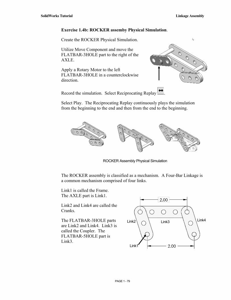
Exercise 1.4b: ROCKER assemby Physical Simulation.
Create the ROCKER Physical Simulation.
Utilize Move Component and move the FLATBAR-3HOLE part to the right of the AXLE.
Apply a Rotary Motor to the left FLATBAR-3HOLE in a counterclockwise direction.
Record the simulation. Select Reciprocating Replay .
Select Play. The Reciprocating Replay continuously plays the simulation from the beginning to the end and then from the end to the beginning.
The ROCKER assembly is classified as a mechanism. A Four-Bar Linkage is a common mechanism comprised of four links.
Link1 is called the Frame. The AXLE part is Link1.
Link2 and Link4 are called the Cranks.
The FLATBAR-3HOLE parts are Link2 and Link4. Link3 is called the Coupler. The FLATBAR-5HOLE part is Link3.
ROCKER Assembly Physical Simulation
Link1
Link3 Link2 Link4
Copyrighted Material
Copyrighted
Material
Copyrighted Material
Copyrighted
Material
Linkage Assembly SolidWorks Tutorial
PAGE 1 - 80
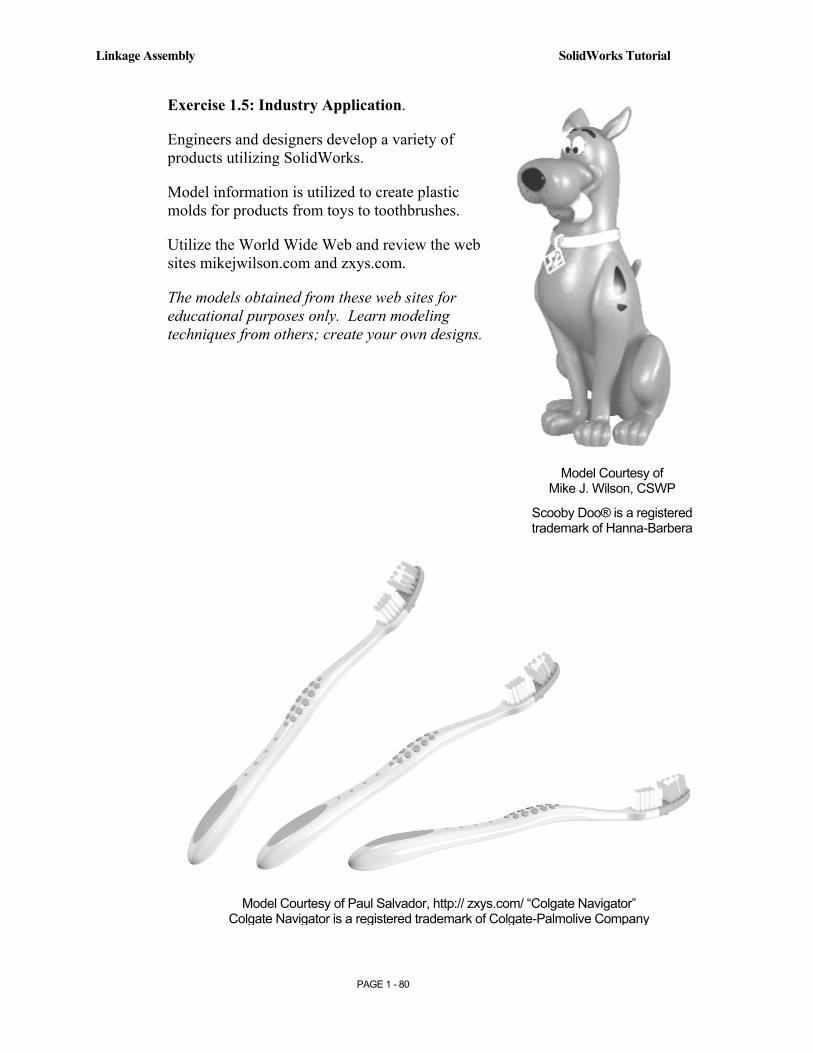
Exercise 1.5: Industry Application.
Engineers and designers develop a variety of products utilizing SolidWorks.
Model information is utilized to create plastic molds for products from toys to toothbrushes.
Utilize the World Wide Web and review the web sites mikejwilson.com and zxys.com.
The models obtained from these web sites for educational purposes only. Learn modeling techniques from others; create your own designs.
Model Courtesy of Paul Salvador, http:// zxys.com/ “Colgate Navigator” Colgate Navigator is a registered trademark of Colgate-Palmolive Company
Model Courtesy of Mike J. Wilson, CSWP
Scooby Doo® is a registered trademark of Hanna-Barbera
Copyrighted Material
Copyrighted
Material
Copyrighted Material
Copyrighted
Material
SolidWorks Tutorial Linkage Assembly
PAGE 1 - 81
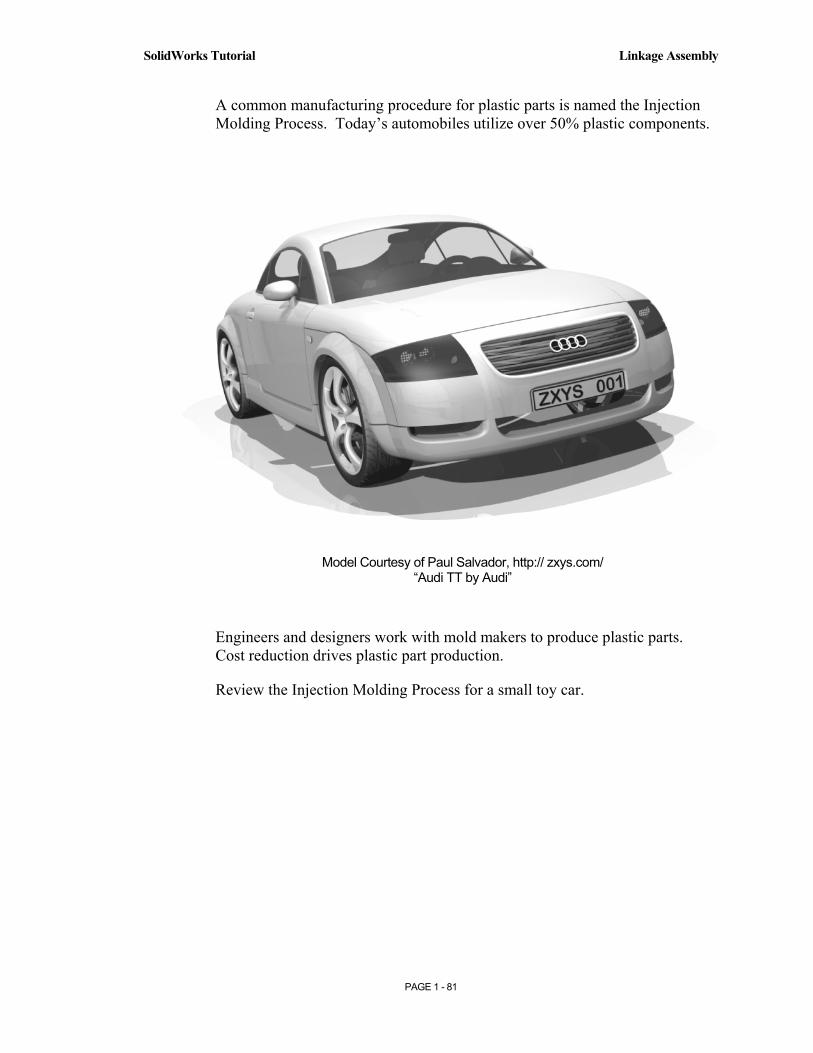
A common manufacturing procedure for plastic parts is named the Injection Molding Process. Today’s automobiles utilize over 50% plastic components.
Engineers and designers work with mold makers to produce plastic parts. Cost reduction drives plastic part production.
Review the Injection Molding Process for a small toy car.
Model Courtesy of Paul Salvador, http:// zxys.com/ “Audi TT by Audi”

Copyrighted Material
Copyrighted
Material
Copyrighted Material
Copyrighted
Material
Linkage Assembly SolidWorks Tutorial
PAGE 1 - 82
The Injection Molded Process. Lee Plastics of Sterling, MA is a precision injection molding company. Through the World Wide Web (www.leeplastics.com), review the injection molded manufacturing process.
The injection molding process is as follows:
An operator pours the plastic resin in the form of small dry pellets, into a hopper. The hopper feeds a large auger screw. The screw pushes the pellets forward into a heated chamber. The resin melts and accumulates into the front of the screw.
At high pressure, the screw pushes the molten plastic through a nozzle, to the gate and into a closed mold, (Plates A & B). Plates A and B are the machined plates that you will design in this project.
The plastic fills the part cavities through a narrow channel called a gate.
The plastic cools and forms a solid in the mold cavity. The mold opens, (along the parting line) and an ejection pin pushes the plastic part out of the mold into a slide.
Injection Molded Process (Courtesy of Lee Plastics, Inc.)
Plastic Resin
Plate A Plate B
Hopper
Screw
Gate
![1 1 1 1 1 1 1 ¢ 1 1 1 - pdfs.semanticscholar.org€¦ · 1 1 1 [ v . ] v 1 1 ¢ 1 1 1 1 ý y þ ï 1 1 1 ð 1 1 1 1 1 x](https://img.pdfslide.us/doc/110x75/5f7bc722cb31ab243d422a20/1-1-1-1-1-1-1-1-1-1-pdfs-1-1-1-v-v-1-1-1-1-1-1-y-1-1-1-.jpg)


![1 $SU VW (G +LWDFKL +HDOWKFDUH %XVLQHVV 8QLW 1 X ñ 1 … · 2020. 5. 26. · 1 1 1 1 1 x 1 1 , x _ y ] 1 1 1 1 1 1 ¢ 1 1 1 1 1 1 1 1 1 1 1 1 1 1 1 1 1 1 1 1 1 1 1 1 1 1 1 1 1 1](https://img.pdfslide.us/doc/110x75/5fbfc0fcc822f24c4706936b/1-su-vw-g-lwdfkl-hdowkfduh-xvlqhvv-8qlw-1-x-1-2020-5-26-1-1-1-1-1-x.jpg)


![$1RYHO2SWLRQ &KDSWHU $ORN6KDUPD +HPDQJL6DQH … · 1 1 1 1 1 1 1 ¢1 1 1 1 1 ¢ 1 1 1 1 1 1 1w1¼1wv]1 1 1 1 1 1 1 1 1 1 1 1 1 ï1 ð1 1 1 1 1 3](https://img.pdfslide.us/doc/110x75/5f3ff1245bf7aa711f5af641/1ryho2swlrq-kdswhu-orn6kdupd-hpdqjl6dqh-1-1-1-1-1-1-1-1-1-1-1-1-1-1.jpg)