Embed Size (px)
Citation preview
FEST
E DR
EHZA
HLEN
G 10
00 D
E GB
FR
D-22934 Bargteheide/Hamburg · P.O.BOX 1262 · Rudolf-Diesel-Str. 1 Fon +49 45 32 4 01-0 · Fax +49 45 32 4 01 2 53 · www.nord.com
Mat
. Nr.
6000
099.
4710
I N T E L L I G E N T D R I V E S Y S T E M S , W O R L D W I D E S E R V I C E S
FESTE DREHZAHLEN C O N S T A N T S P E E D S V I T E S S E S C O N S T A N T E S
G 1000 DE GB FR
G 1000 IE1 02_12_Umschlag 21 mm.indd 1 09.02.12 13:21
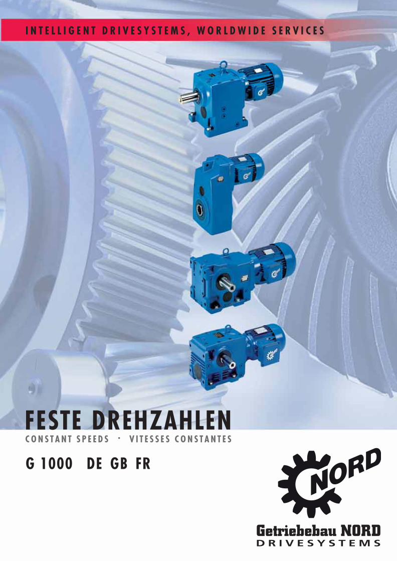
InhaltsübersichtTable of ContentsSommaire
www.nord.com I
Technische Erläuterungen - GetriebeExplanatory Notes - Gear UnitsDescription techniques - Réducteurs....................A 1
StirnradgetriebeHelical Gear UnitsRéducteurs à engrenages cylindriques ................B 1
FlachgetriebeParallel Shaft Gear UnitsRéducteurs à arbres paralléles.............................C 1
KegelradgetriebeHelical-Bevel Gear UnitsRéducteurs à couple conique ...............................D 1
Stirnrad-SchneckegetriebeHelical-Worm Gear UnitsRéducteurs à roue et vis sans fin .........................E 1
InhaltsübersichtTable of ContentsSommaire
II www.nord.com
MotorenMotorsMoteurs................................................................ F 1
Bremsmotoren und BremsenBrake Motors and BrakesMoteurs-frein et Freins ........................................G 1
Allgemeine ErsatzteileGeneral Parts ListVues éclatées et nomenclature ...........................H 1

Technical
Explanations
www.nord.com G1000 A1 GB
DESCRIPTIONS OF GEAR UNITS Helical gear units . . . . . . . . . . . . . . . . . . . . . . . . . . . . . . . . . A2 Parallel shaft gear units . . . . . . . . . . . . . . . . . . . . . . . . . . . . A2 Helical-bevel gear units . . . . . . . . . . . . . . . . . . . . . . . . . . . . A3 Helical worm gear units . . . . . . . . . . . . . . . . . . . . . . . . . . . . A3 W and IEC adapters . . . . . . . . . . . . . . . . . . . . . . . . . . . . . . . A4 MK top mount motor platform . . . . . . . . . . . . . . . . . . . . . . . . A4NOTES ON GEAR UNITS AND GEARED MOTORS Vertical mounting positions . . . . . . . . . . . . . . . . . . . . . . . . . . A5 External installation . . . . . . . . . . . . . . . . . . . . . . . . . . . . . . . . A5 Special ambient conditions . . . . . . . . . . . . . . . . . . . . . . . . . . A5 Storage before installation . . . . . . . . . . . . . . . . . . . . . . . . . . A5 Vents . . . . . . . . . . . . . . . . . . . . . . . . . . . . . . . . . . . . . . . . . . . A5 Multi-stage gear units . . . . . . . . . . . . . . . . . . . . . . . . . . . . . . A5 Drives for aerators, agitators, mixers and fans . . . . . . . . . . . A5GEAR SELECTION Criteria . . . . . . . . . . . . . . . . . . . . . . . . . . . . . . . . . . . . . . . . . A6 Drive power and service factor . . . . . . . . . . . . . . . . . . . . . . . A6 Classification of an operation (of uniformity) . . . . . . . . . . . . . A7 Overhung and axial forces . . . . . . . . . . . . . . . . . . . . . . . . . . A9NOMENCLATURE . . . . . . . . . . . . . . . . . . . . . . . . . . . . . . . . . . A10AVAILABLE DESIGNS Overview . . . . . . . . . . . . . . . . . . . . . . . . . . . . . . . . . . . . . . . . A14 Examples . . . . . . . . . . . . . . . . . . . . . . . . . . . . . . . . . . . . . . . A15TECHNICAL EXPLANATIONS Shrink discs . . . . . . . . . . . . . . . . . . . . . . . . . . . . . . . . . . . . . A22 Fixing elements, rubber buffers . . . . . . . . . . . . . . . . . . . . . . A27 Reinforced output shaft bearing VL2/VL3 . . . . . . . . . . . . . . . A30 Backstops, rotational direction . . . . . . . . . . . . . . . . . . . . . . . A31 Adapter for mounting servomotors . . . . . . . . . . . . . . . . . . . . A33 Motor brackets . . . . . . . . . . . . . . . . . . . . . . . . . . . . . . . . . . . A34 Oil expansion chamber . . . . . . . . . . . . . . . . . . . . . . . . . . . . . A37 Oil tank . . . . . . . . . . . . . . . . . . . . . . . . . . . . . . . . . . . . . . . . . A38 Oil cooler . . . . . . . . . . . . . . . . . . . . . . . . . . . . . . . . . . . . . . . . A39 Water cooling . . . . . . . . . . . . . . . . . . . . . . . . . . . . . . . . . . . . A40 Lubricants . . . . . . . . . . . . . . . . . . . . . . . . . . . . . . . . . . . . . . . A41 Lubricants for anti-friction bearings . . . . . . . . . . . . . . . . . . . . A42 Symbols for oil plugs in mounting positions . . . . . . . . . . . . . A43 Coating . . . . . . . . . . . . . . . . . . . . . . . . . . . . . . . . . . . . . . . . . A43INFORMATION AND DEFINITIONS Information about the dimension drawings . . . . . . . . . . . . . A44 Addition sample for dimension drawings . . . . . . . . . . . . . . . A44 Tolerances . . . . . . . . . . . . . . . . . . . . . . . . . . . . . . . . . . . . . . A45 Abbreviations in the output and selection Tables . . . . . . . . . A45 Structure of the performance tables Type Geared Motors . . . . . . . . . . . . . . . . . . . . . . . . . . . . . A46 Type W and IEC . . . . . . . . . . . . . . . . . . . . . . . . . . . . . . . . A47 Position of the shafts, flanges, torque arms and shrink discs for angular gear units . . . . . . . . . . . . . . . . . A48 Terminal box and cable entry . . . . . . . . . . . . . . . . . . . . . . . . A49 Mounting Positions . . . . . . . . . . . . . . . . . . . . . . . . . . . . . . . . A51TABLES Mounting positions with plugs . . . . . . . . . . . . . . . . . . . . . . . . A53 Oil Fill Volumes . . . . . . . . . . . . . . . . . . . . . . . . . . . . . . . . . . . A59 Maximum torque M2max . . . . . . . . . . . . . . . . . . . . . . . . . . . . A62 Overhung load conversion tables: output . . . . . . . . . . . . . . . A64 Overhung and axial loads for type W adapter . . . . . . . . . . . A66 Gear units with flange on drive side . . . . . . . . . . . . . . . . . . . A69
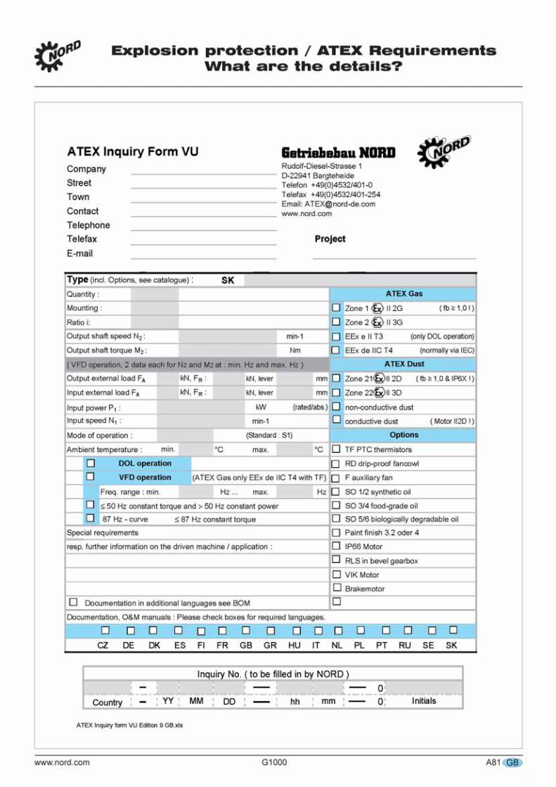
EXPLOSION PROTECTION/ATEX REQUIREMENTS . . . . A75-A81
Technical Explanations
A2 G1000 www.nord.comGB
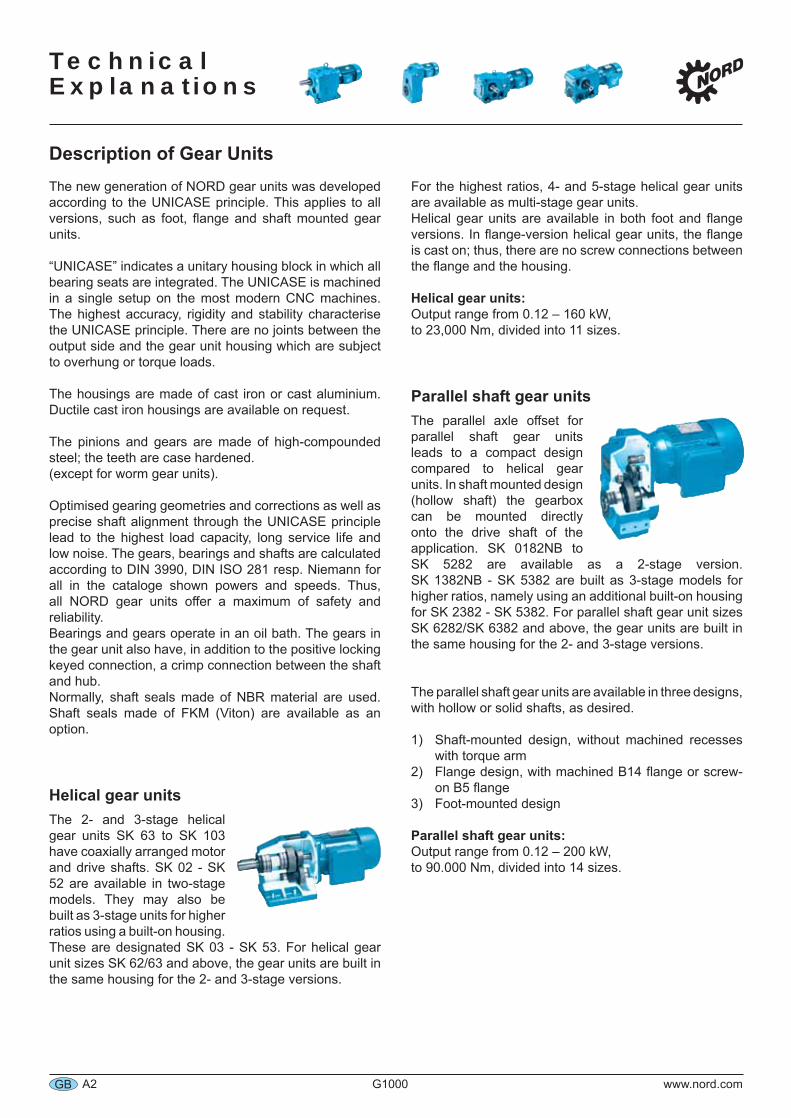
Description of Gear UnitsThe new generation of NORD gear units was developed according to the UNICASE principle. This applies to all versions, such as foot, flange and shaft mounted gear units.
“UNICASE” indicates a unitary housing block in which all bearing seats are integrated. The UNICASE is machined in a single setup on the most modern CNC machines. The highest accuracy, rigidity and stability characterise the UNICASE principle. There are no joints between the output side and the gear unit housing which are subject to overhung or torque loads.
The housings are made of cast iron or cast aluminium. Ductile cast iron housings are available on request.
The pinions and gears are made of high-compounded steel; the teeth are case hardened.(except for worm gear units).
Optimised gearing geometries and corrections as well as precise shaft alignment through the UNICASE principle lead to the highest load capacity, long service life and low noise. The gears, bearings and shafts are calculated according to DIN 3990, DIN ISO 281 resp. Niemann for all in the cataloge shown powers and speeds. Thus, all NORD gear units offer a maximum of safety and reliability.Bearings and gears operate in an oil bath. The gears in the gear unit also have, in addition to the positive locking keyed connection, a crimp connection between the shaft and hub.Normally, shaft seals made of NBR material are used. Shaft seals made of FKM (Viton) are available as an option.
Helical gear unitsThe 2- and 3-stage helical gear units SK 63 to SK 103 have coaxially arranged motor and drive shafts. SK 02 - SK 52 are available in two-stage models. They may also be built as 3-stage units for higher ratios using a built-on housing. These are designated SK 03 - SK 53. For helical gear unit sizes SK 62/63 and above, the gear units are built in the same housing for the 2- and 3-stage versions.
For the highest ratios, 4- and 5-stage helical gear units are available as multi-stage gear units.Helical gear units are available in both foot and flange versions. In flange-version helical gear units, the flange is cast on; thus, there are no screw connections between the flange and the housing.
Helical gear units:Output range from 0.12 – 160 kW,to 23,000 Nm, divided into 11 sizes.
Parallel shaft gear unitsThe parallel axle offset for parallel shaft gear units leads to a compact design compared to helical gear units. In shaft mounted design (hollow shaft) the gearbox can be mounted directly onto the drive shaft of the application. SK 0182NB to SK 5282 are available as a 2-stage version. SK 1382NB - SK 5382 are built as 3-stage models for higher ratios, namely using an additional built-on housing for SK 2382 - SK 5382. For parallel shaft gear unit sizes SK 6282/SK 6382 and above, the gear units are built in the same housing for the 2- and 3-stage versions.
The parallel shaft gear units are available in three designs, with hollow or solid shafts, as desired.
Shaft-mounted design, without machined recesses with torque armFlange design, with machined B14 flange or screw-on B5 flangeFoot-mounted design
Parallel shaft gear units:Output range from 0.12 – 200 kW,to 90.000 Nm, divided into 14 sizes.
1)
2)
3)

Technical
Explanations
www.nord.com G1000 A3 GB
Helical-bevel gear unitsHelical-bevel gear units are angular gear units in which the motor shaft and the output shaft form a 90° angle. Through this, a beneficial spatial arrangement of the drive arises. NORD helical-bevel gear units always have multiple gear stages.
The configuration of stages is a follows:
2-stage 3-stage 4-stageHelical stageHelical stageBevel gear stageHelical stage
--1.stage2.stage
--
--1.stage2.stage3.stage
1.stage2.stage3.stage4.stage
Helical-bevel gear units are available with an integrated backstop.
The bevel gear can be placed to the left or right of the bevel pinion, through which the direction of rotation between the drive shaft and output shaft reverses.
Efficiency η:The great advantage of the helical-bevel gear unit is the almost constant efficiency over the entire gear ratio range that practically equals that of helical and parallel shaft gear units.
Helical-bevel gear units:Output range from 0.12 – 200 kW,to 50.000 Nm, divided into 16 sizes.
Helical-worm gear unitsHelical-worm gear units are angular gear units in which the motor shaft and the output shaft form a 90° angle. Through this, a beneficial spatial arrangement of the drive arises. The helical worm gear units listed in this catalogue have multiple stages. NORD also has very economically priced single-stage worm gear series which are listed in catalogue G1035. Please request our catalogue G1035.
The helical gears of the helical worm gear units are made of high-compounded steel; the theeth are case hardened. Optimised gearing geometries and corrections as well as precise shaft alignment through the UNICASE principle lead to the highest load capacity, long service life and low noise. The worm stage has a hardened cylinder worm as well as a worm gear with a welded-on rim made of optimised special bronze. This combination guarantees a long service life. By using the most modern CNC processing machines, we offer the highest possible production quality ensured by constant inspection.
The helical worm gear unit series is lubricated for life at the factory with a high-quality, synthetic long-life lubricant with a polyglycol base. This synthetic lubricant leads to very high efficiency and a long service life through reduced friction.The helical worm gear units SK 02040 to SK 42125 are available in two-stage models. They may also be built as 3-stage units for higher ratios using a built-on housing. These are designated SK 13050 - SK 43125.
Helical worm gear units:Output range from 0.12 – 15 kW,to 3.000 Nm, divided into 6 sizes.
Efficiency η:NORD worm gear units achieve efficiencies up to 92%.Because the worm gear set in new gear units must be run in, the friction coefficient is larger before running in than after. Because of this, the efficiency is slightly lower than before running in. This effect is increased at lower incline angles, thus with a lower number of starts in the worm.Based on experience, the following allowances should be made:
- 1 gear up to approx. 12%- 2 gears up to approx. 6%- 3 gears up to approx. 3%- 6 gears up to approx. 2%
The number of worm threads is listed in the output and gear ratio tables. The run-in procedure is completed after approx. 25 hours operating time at maximum load. The following conditions must be met in order to achieve the efficiencies shown in the tables:
- gear unit is fully run-in- gear unit has reached a constant temperature- the required lubricant is filled- the rated torque must be taken off from the gear unit
Technical Explanations
A4 G1000 www.nord.comGB
W and IEC adaptersWith type W gear units (with free input shafts), the maximum drive output listed in the output and gear ratio tables is valid. With type IEC gear units, the standard power of each size according to DIN EN 50347 applies, but with the maximum power listed in the output and gear ratio tables. With rotation speeds higher than those listed in the output and gear ratio tables, special measures may be required. Please enquire.
With type W gear units, the input shaft bearings must be lubricated regularly (for two-stage gear units sizes SK 62 and SK 6282 and above and three-stage gear units sizes SK 73, SK 7382 and SK 9072.1 and above). We recommend that the exterior anti-friction bearings of the input shaft be lubricated, using the lubricating nipple provided, with approx. 20 to 25 g of grease approx. every 2,500 operating hours. Recommended lubricants: Petamo GHY 133 N (Klüber Lubrication). For the free input shaft an automatic lubricator as well as an external fan to improve the gearbox cooling are available on request, please enquire.
Two stage gear units with IEC adapter ≥ 160 of sizes SK 62 and SK 6282 and greater and three-stage gear units with IEC adapter ≥ 160 of sizes SK 73, SK 7382 and SK 9072.1 and greater normally have an automatic lubricator that supplies the external anti-friction bearings of the drive shaft with lubricant (see page H18, item 145). The lubricator supplies permanent lubricant to the bearing. The lubricator is filled with 120 cm3 of grease. Before commissioning the gear unit, the automatic lubricator should be activated and then exchanged every 12 months. This applies for an average run time ≤ 8 hours/day. With longer run times, the interval between exchanging is reduced to 6 months.
The lubricator is designed for normal use at ambient temperatures from 0°C to 40°C. If the ambient temperature differs from the specified standard value for longer periods of time, special lubricators should be used: please enquire.
The IEC adapter with motor size ≥ 160 with the automatic lubricator is, under certain operating conditions, normally not recommended for vertical mounting positions in which the motor is vertically upright. In this case, the direct mounted motor is strictly recommended.The vertical IEC adapter with motor size ≥ 160 (mounting position M2 or M4) must be checked and approved by NORD (with the actual operating conditions). Please pay to attation to this.In vertical alignments with motor downwards (mounting position M2), the service life of the seal may be decreased.
In this case, we recommend shorter intervals between maintenance. The smaller gear units with IEC adapters up to size SK 52 and SK 5282 (for two-stage gear units) and up to size SK 63, SK 6382 and SK 9052.1 (for three-stage gear units) have bearings which are specially sealed and lubricated for their service life. These are maintenance-free.The IEC adapter coupling for motor sizes 63 to 180 is not fail-safe. (Exception: IEC motor sizes 160 and 180 if the automatic lubricator is used. From IEC 200 and higher, the couplings used are fail-safe.) With hoists, lifts and other cases of operation with a danger of personal injury, special measures are required: we ask you to enquire about this.
Compared to the direct mounted motor, the IEC adapter has an additional shaft coupling and additional bearing seats. Compared to the direct mounted motor, there are higher no-load losses. We recommend to mount the motor directly, since it not only offers technical advantages, but also offers price advantages.
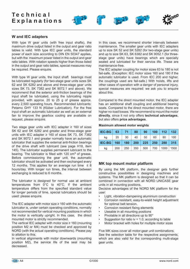
Maximum allowed motor weights
IEC-BG 63 71 80 90 100 112 132kg 25 30 40 50 60 80 100
IEC-BG 160 180 200 225 250 280 315kg 200 250 350 500 700 1000 1500
MK top mount motor platformBy using the MK platform, the designer gets further constructive possibilities in designing machines and systems. The MK platform is designed so that it can be combined in connection with all NORD UNICASE gear units in all mounting positions.Decisive advantages of the NORD MK platform for the user:
Light, vibration-dampening aluminium constructionCorrosion resistant, easy-to-wield height adjustment for optimal belt tension.Corrosion resistant fixing elementsUseable in all mounting positionsPivotable in all directions up to 90°Suggestion for ratio iv = 1.0, according to tableMotor bracket with holes for multiple motor sizes
Five MK sizes cover all motor-gear unit combinations.See the selection table for the respective assignments, which are also valid for the corresponding multi-stage gear units.
••
•••••
Technical
Explanations
www.nord.com G1000 A5 GB
Vertical mounting position for gear units and gear motorsGear units and gear motors may be mounted in positions with vertical shafts. (Exception: IEC adapters with certain sizes). For these mounting positions, the gear units are filled with increased amounts of lubricant. Some gearbox types are also equipped with specially sealed, grease lubricated bearings. These mounting positions show increased oil-splashing-losses, causing a higher temperature rise in operation (observe thermal limit rating – see page A6). For motors which are mounted vertically upwards (mounting position M4) and ratios < 20, we imperatively recommend oil expansion chambers in order to avoid leakage through the vent plug. Please contact us so that we can suggest an appropriate solution for the particular drive situation.
External installation, tropical useWhen installed externally, in damp rooms, or used in the tropics, special seals and anti-corrosion measures are required. Please inform us of such upon ordering.
Special ambient conditions Special ambient conditions are. for example:
aggressive or corrosive materials (contaminated air, gases, acids, bases, salts, etc.) in the surroundingsvery high relative humidity or contact between the gear unit motor and liquidsstrong dirt, dust or sand deposits on the gear unit motorstrong atmospheric pressure variationsradiationextremely high or low ambient temperature or temperature changesvibrations, accelerations, shocks, impacts or other abnormal ambient conditions
If special ambient conditions exist, including those which occur during transport or storage before commissioning, these should be taken into account during the project planning phase. Please enquire.
Storage before commissioningThe gear units and gear unit motors should only be stored in a dry area before commissioning. Special measures are required for longer storage. Please request the “Operating and Assembly Instructions B1000”, which are available for download on the Internet at www.nord.com.
•
•
•
•••
•
VentsThe gear units (except for SK 0182NB, SK 0282NB and SK 1382NB) are normally equipped with a vent which compensates for air pressure differences between the inner space of the gear unit and the atmosphere. This vent is closed upon delivery in order to avoid oil leakage during transport. Before commissioning, the vent should be activated by removing the sealing plug. Pressure vents are optionally available.
Multi-stage gear units
With four-, five- and six-stage multi-stage gear units, there is a relevant no-load loss because of the many rotating parts and the relatively small drive input power. Thus, a no-load loss of approx. 40 watts for 4-pole motors up to 0.75 kW is accounted in the perfomence tables.
Drives for aerators, agitators, mixers and fansDrives for aerators, agitators and mixers in sewage treatment plants, in anaerobic digesters for biogas and in process engineering as well as fan drives (e.g. in cooling towers) are normally subject to extremely hard operating conditions:
continuous 24h-operation at the rated power torque or rated outputhigh mass inertia on the output at lower gear unit ratiosvibrations in the drive train as well as high flexural bending moments and forces on the output shaft when the mixer and/or fan shaft are positioned directly on the gear unitvertical alignmentexternal installation, i.e. moisture and aggressive media as well as large temperature changes with condensationa high degree of environmental protection is required, e.g. fully leak-proof, safe oil maintenance and low noise level
Based on experience, NORD has developed a package of special measures in order to meet the needs of special operating conditions. NORD thus strongly recommends that you provide for these special measures; please enquire. A minimum service factor of fB 1,7 must be selected for drives on agitators and mixers because of their extreme duty. NORD recommends a service factor fB of higher than 2,0. Drives running on frequency inverters may experience control-induced vibrations e.g. from a slip-compensation. Such vibrations must be avoided. Please observe that a possible speed increase via frequency inverter will increase the absorbed power by the third power. Therefore the minimum service factor fB must always refer to the highest operating speed.
•
•
•
••
•
Notes on Gear units and Gear Unit Motors
Technical Explanations
A6 G1000 www.nord.comGB
Gear Unit SelectionSelecting a gear unit presupposes NORD three-phase asynchronous AC-motors or single phase AC-motors and also applies for technically comparable motors. When using other motors, please consult with NORD.If the following important guidelines for selecting a gear unit are not adhered to, an overload is likely. In this case, all warranties are inapplicable.When in doubt, please contact the NORD sales office which is responsible for you so that we may work together to check the gear unit design. In our mutual interests, all problems caused by overloading the gear units should be avoided in every case.
CriteriaSelection criteria constitute:
The mechanically transferable power P - this is considered by the service factor fB in the relevant table in the catalogue. The next chapter describes the determination of the required service factor.The thermally transferable power (thermal limit) - this should not be exceeded over a longer time period (3 hours) so that the gear unit does not overheat. The thermally transferable power only represents a possible limit for larger gear units of size SK 62 and SK 6282 and greater (for two-stage gear units) and of size SK 73, SK 7382 and SK 9072.1 and greater (for three-stage gear units). We recommend that you consult with NORD and check the specific operational situation exactly when two or more of the following items apply:vertical alignment (mounting position M2 or M4, see page A51)motor mount of type IEC, or type W free drive shaftdrive power P1 > 100 kWratio iges < 20 (for helical-bevel gear units iges < 40)drive speed n1 > 1500 min-1
elevated ambient temperature > 40°C
In general, we ask that you consult with us when there are special installation conditions, such as enclosing the gear unit, heat radiation, confined space, etc. Special measures (oil cooler, etc.) are available against thermal overload; please enquire.
1.
2.
•
•••••
Input power and service factorThe required input power for each application is determined by measurement or calculation. The rated power of the motor P1 is to be selected after this. It is normally slightly higher than the required power because safety factors for special operating conditions of the specific application are to be observed, and rated motor output levels are generally available in standard output level ranges. Short-term and infrequent torque impulses do not need to be accounted for when selecting the rated power of a three-phase AC-motor to be installed. When operating a three-phase AC-motor on a frequency inverter, additional factors influence the selection of the rated output; in this case, we ask for your detailed enquiry.
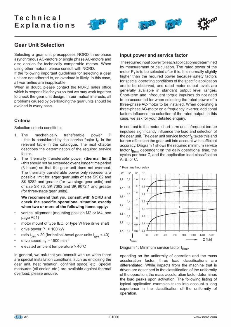
In contrast to the motor, short-term and infrequent torque impulses significantly influence the load and selection of the gear unit. The gear unit service factor fB takes this and further effects on the gear unit into account with sufficient accuracy. Diagram 1 shows the required minimum service factor fBmin dependent on the daily operational time, the cycles per hour Z, and the application load classification A, B, or C.
* Run time hours/day
Diagram 1: Minimum service factor fBmin
epending on the uniformity of operation and the mass acceleration factor, three load classifications are differentiated. While impacts from the machine that is driven are described in the classification of the uniformity of the operation, the mass acceleration factor determines the load peaks upon activation. The following listing of typical application examples takes into account a long experience in the classification of the uniformity of operation.
Z [1/h]fBmin
Technical
Explanations
www.nord.com G1000 A7 GB
Selecting a Gear UnitClassification of an operation (of uniformity):
A) uniform operation Light screw conveyors, fans, assembly belts, light conveyor belts, small agitators, elevators, cleaning machines, filling machines, testing machines and belt conveyors.
B) moderate shocks, non-uniform operation Decoilers, feed drives for wood processing machines, hoists, balancing machines, tapping units, heavy conveyor, belts, winches, sliding doors, stall dunging machines, packaging machines, cement mixers, crane travelling mechanisms, mills, bending machines and gear pumps.
C) heavy shocks, extreme non-uniform operation Stirrers and mixers, shears, presses, centrifuges, rolling stands, heavy winches and lifts, grinding mills, stone crushers, bucket elevators, punching machines, hammer mills, eccentric presses, folding machines, roller tables, tumbling barrels, choppers, shredders, vibrators.
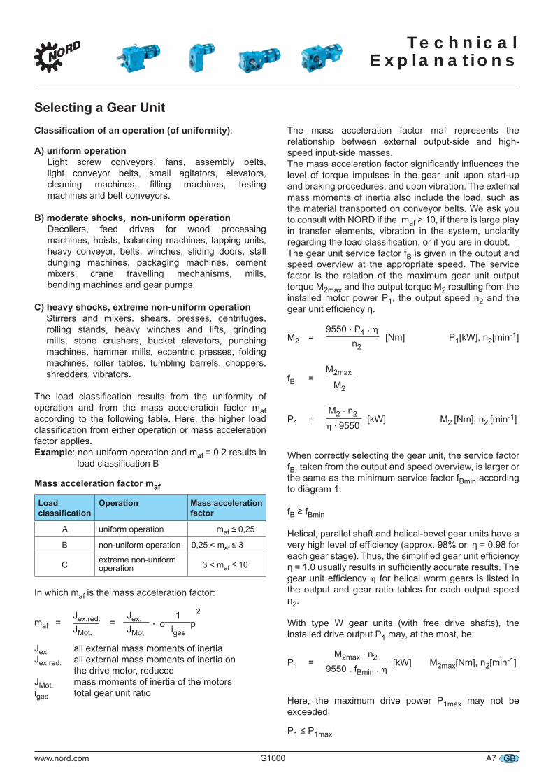
The load classification results from the uniformity of operation and from the mass acceleration factor maf according to the following table. Here, the higher load classification from either operation or mass acceleration factor applies. Example: non-uniform operation and maf = 0.2 results in load classification B
Mass acceleration factor maf
Load classification
Operation Mass acceleration factor
A uniform operation maf ≤ 0,25
B non-uniform operation 0,25 < maf ≤ 3
C extreme non-uniform operation 3 < maf ≤ 10
In which maf is the mass acceleration factor:
JMot.
1Jex.Jex.red.JMot.
2. po iges
maf = =
Jex. all external mass moments of inertia Jex.red. all external mass moments of inertia on the drive motor, reducedJMot. mass moments of inertia of the motorsiges total gear unit ratio
The mass acceleration factor maf represents the relationship between external output-side and high-speed input-side masses. The mass acceleration factor significantly influences the level of torque impulses in the gear unit upon start-up and braking procedures, and upon vibration. The external mass moments of inertia also include the load, such as the material transported on conveyor belts. We ask you to consult with NORD if the maf > 10, if there is large play in transfer elements, vibration in the system, unclarity regarding the load classification, or if you are in doubt.The gear unit service factor fB is given in the output and speed overview at the appropriate speed. The service factor is the relation of the maximum gear unit output torque M2max and the output torque M2 resulting from the installed motor power P1, the output speed n2 and the gear unit efficiency η.
M2 = [Nm] P1[kW], n2[min-1]9550 . P1 . η
n2
fB = M2max
M2
P1 = [kW] M2 [Nm], n2 [min-1] M2 . n2η ⋅ 9550
When correctly selecting the gear unit, the service factor fB, taken from the output and speed overview, is larger or the same as the minimum service factor fBmin according to diagram 1.
fB ≥ fBmin
Helical, parallel shaft and helical-bevel gear units have a very high level of efficiency (approx. 98% or η = 0.98 for each gear stage). Thus, the simplified gear unit efficiency η = 1.0 usually results in sufficiently accurate results. The gear unit efficiency η for helical worm gears is listed in the output and gear ratio tables for each output speed n2.
With type W gear units (with free drive shafts), the installed drive output P1 may, at the most, be:
P1 = [kW] M2max[Nm], n2[min-1]M2max . n2
9550 . fBmin . η
Here, the maximum drive power P1max may not be exceeded.
P1 ≤ P1max
Technical Explanations
A8 G1000 www.nord.comGB
Selecting a Gear UnitThe performence tables type W and IEC list for each output speed n2 the maximum gear unit output torque M2max and the maximum motor power P1max.
With brakes attached to the drive side, such as braking motors, the brake torque should also be considered in selecting a gear unit. For applications with relatively high external mass moments of inertia (maf > 2) – such as is often the case with travel drives, slewing gears, rotary tables, gate drives, agitators and surface aerators – we recommend that a braking torque that does not exceed 1.2 times the rated motor torque is selected. If higher braking torques are to be used, this should be considered when selecting the gear unit. Please enquire.
Energy efficient motors with the classification EFF1 and EPAct (see page F14) have higher breakdown torques and performance reserves. These may, when required by the application and not limited electrically, provide a non-admissible high performance permently. This should be considered when selecting a gear unit.
Especially unusual applications and extraordinarily extreme modes of operation, such as blockages, movements against solid limit stops, reversing while in motion, changing standstill loads, and gear ratios into fast speeds must be particularly considered when selecting a gear unit. Please enquire.
Especially for worm gear units:When designing worm gear units, you should consider that multi-start worms (reduced possibility of self-locking) should be used when torque impulses, back driving output torques or large mass acceleration factors maf can occur. The number of worm threads z1 is listed in the output and gear ratio tables. These apply:
maf ≤ 0,25 all numbers of worm threads are possiblemaf ≤ 3,00 numbers of worm threads z1 ≥ 3 is recommendedmaf ≤ 10,00 numbers of worm threads z1 ≥ 6 is recommended
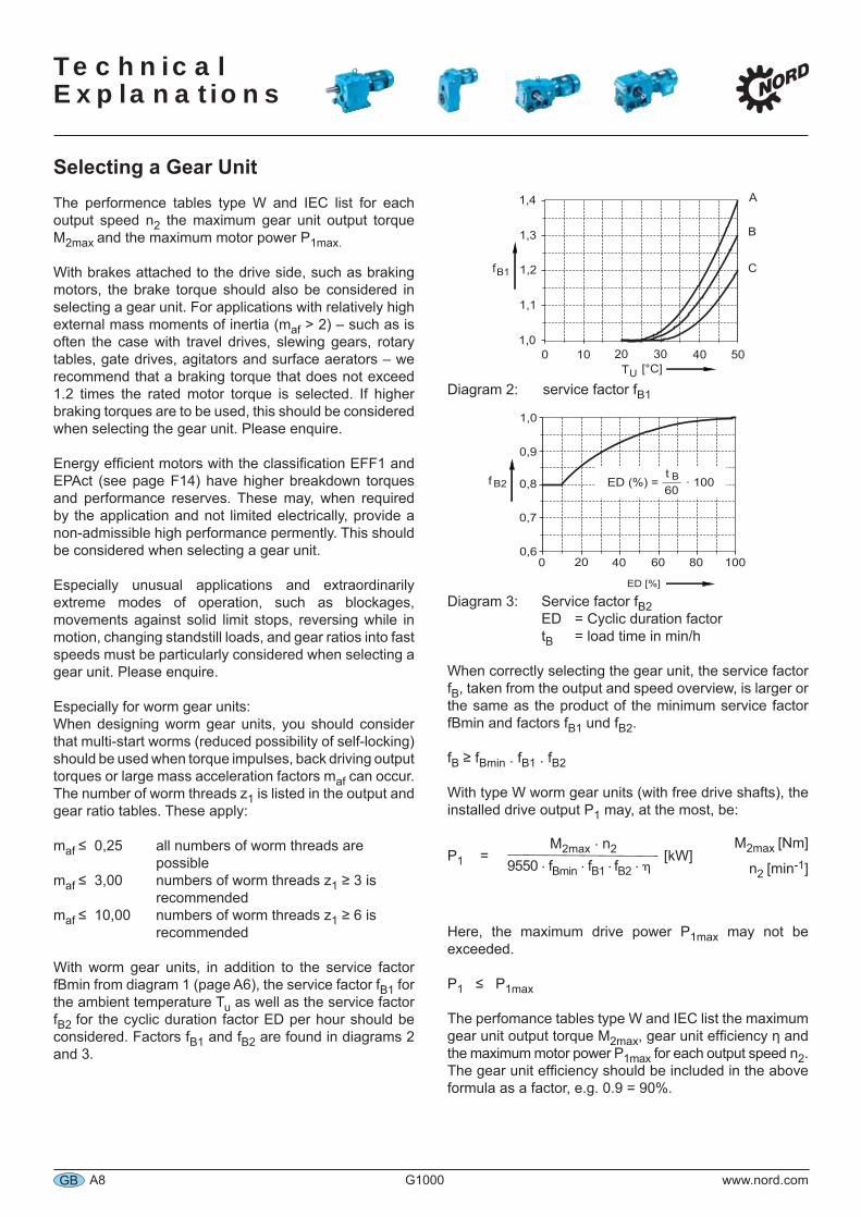
With worm gear units, in addition to the service factor fBmin from diagram 1 (page A6), the service factor fB1 for the ambient temperature Tu as well as the service factor fB2 for the cyclic duration factor ED per hour should be considered. Factors fB1 and fB2 are found in diagrams 2 and 3.
Diagram 2: service factor fB1
Diagram 3: Service factor fB2 ED = Cyclic duration factor tB = load time in min/h
When correctly selecting the gear unit, the service factor fB, taken from the output and speed overview, is larger or the same as the product of the minimum service factor fBmin and factors fB1 und fB2.
fB ≥ fBmin . fB1 . fB2
With type W worm gear units (with free drive shafts), the installed drive output P1 may, at the most, be:
P1 = [kW] M2max . n2
9550 . fBmin . fB1 . fB2 . η
Here, the maximum drive power P1max may not be exceeded.
P1 ≤ P1max
The perfomance tables type W and IEC list the maximum gear unit output torque M2max, gear unit efficiency η and the maximum motor power P1max for each output speed n2. The gear unit efficiency should be included in the above formula as a factor, e.g. 0.9 = 90%.
M2max [Nm]
n2 [min-1]
Technical
Explanations
www.nord.com G1000 A9 GB
Selecting a Gear Unit
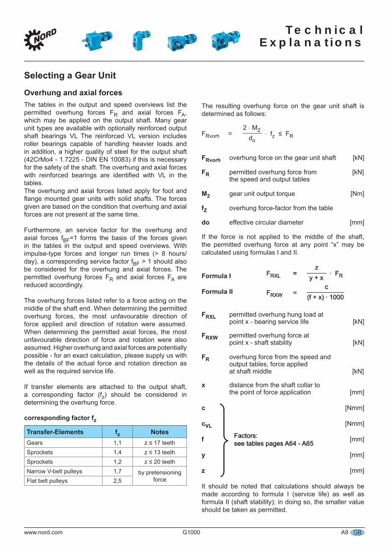
Overhung and axial forcesThe tables in the output and speed overviews list the permitted overhung forces FR and axial forces FA, which may be applied on the output shaft. Many gear unit types are available with optionally reinforced output shaft bearings VL The reinforced VL version includes roller bearings capable of handling heavier loads and in addition, a higher quality of steel for the output shaft (42CrMo4 - 1.7225 - DIN EN 10083) if this is necessary for the safety of the shaft. The overhung and axial forces with reinforced bearings are identified with VL in the tables.The overhung and axial forces listed apply for foot and flange mounted gear units with solid shafts. The forces given are based on the condition that overhung and axial forces are not present at the same time.
Furthermore, an service factor for the overhung and axial forces fBF=1 forms the basis of the forces given in the tables in the output and speed overviews. With impulse-type forces and longer run times (> 8 hours/day), a corresponding service factor fBF > 1 should also be considered for the overhung and axial forces. The permitted overhung forces FR and axial forces FA are reduced accordingly.
The overhung forces listed refer to a force acting on the middle of the shaft end. When determining the permitted overhung forces, the most unfavourable direction of force applied and direction of rotation were assumed. When determining the permitted axial forces, the most unfavourable direction of force and rotation were also assumed. Higher overhung and axial forces are potentially possible - for an exact calculation, please supply us with the details of the actual force and rotation direction as well as the required service life.
If transfer elements are attached to the output shaft, a corresponding factor (fz) should be considered in determining the overhung force.
corresponding factor fz
Transfer-Elements fz NotesGears 1,1 z ≤ 17 teethSprockets 1,4 z ≤ 13 teethSprockets 1,2 z ≤ 20 teethNarrow V-belt pulleys 1,7 by pretensioning
forceFlat belt pulleys 2,5
The resulting overhung force on the gear unit shaft is determined as follows:
FRvorh = . fz ≤ FR2 . M2
do
FRvorh overhung force on the gear unit shaft [kN]
FR permitted overhung force from [kN] the speed and output tables
M2 gear unit output torque [Nm]
fZ overhung force-factor from the table
do effective circular diameter [mm]
If the force is not applied to the middle of the shaft, the permitted overhung force at any point “x” may be calculated using formulas I and II.
Formula I Formula II
FRXL permitted overhung hung load at point x - bearing service life [kN]
FRXW permitted overhung force at point x - shaft stability [kN]
FR overhung force from the speed and output tables, force applied at shaft middle [kN]
x distance from the shaft collar to the point of force application [mm]
c [Nmm]
cVL [Nmm]
f [mm]
y [mm]
z [mm]
It should be noted that calculations should always be made according to formula I (service life) as well as formula II (shaft stability); in doing so, the smaller value should be taken as permitted.
FRXL = . FRz
y + xFRXL = . FR
z y + x
FRXW = c
(f + x) . 1000FRXW =
c(f + x) . 1000
Factors: see tables pages A64 - A65Factors: see tables pages A64 - A65
Technical Explanations
A10 G1000 www.nord.comGB
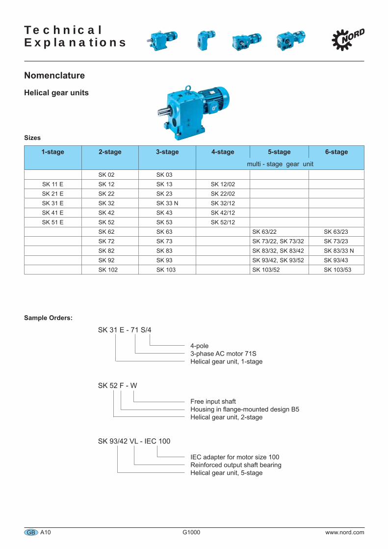
Nomenclature
Helical gear units
Sample Orders:
SK 31 E - 71 S/4
4-pole 3-phase AC motor 71S Helical gear unit, 1-stage
SK 52 F - W
Free input shaft Housing in flange-mounted design B5 Helical gear unit, 2-stage
SK 93/42 VL - IEC 100
IEC adapter for motor size 100 Reinforced output shaft bearing Helical gear unit, 5-stage
Sizes
1-stage 2-stage 3-stage 4-stage 5-stage 6-stage
multi - stage gear unitSK 02 SK 03
SK 11 E SK 12 SK 13 SK 12/02SK 21 E SK 22 SK 23 SK 22/02SK 31 E SK 32 SK 33 N SK 32/12SK 41 E SK 42 SK 43 SK 42/12SK 51 E SK 52 SK 53 SK 52/12
SK 62 SK 63 SK 63/22 SK 63/23SK 72 SK 73 SK 73/22, SK 73/32 SK 73/23SK 82 SK 83 SK 83/32, SK 83/42 SK 83/33 NSK 92 SK 93 SK 93/42, SK 93/52 SK 93/43SK 102 SK 103 SK 103/52 SK 103/53
Technical
Explanations
www.nord.com G1000 A11 GB
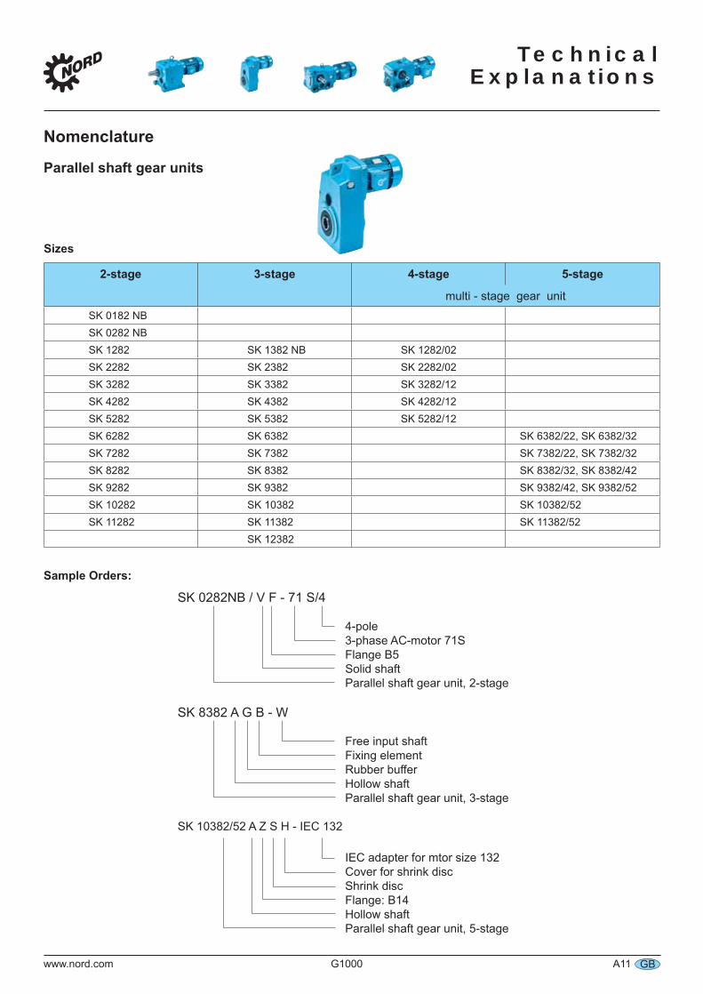
Nomenclature
Parallel shaft gear units
Sizes
2-stage 3-stage 4-stage 5-stage
multi - stage gear unitSK 0182 NBSK 0282 NBSK 1282 SK 1382 NB SK 1282/02SK 2282 SK 2382 SK 2282/02SK 3282 SK 3382 SK 3282/12SK 4282 SK 4382 SK 4282/12SK 5282 SK 5382 SK 5282/12SK 6282 SK 6382 SK 6382/22, SK 6382/32SK 7282 SK 7382 SK 7382/22, SK 7382/32SK 8282 SK 8382 SK 8382/32, SK 8382/42SK 9282 SK 9382 SK 9382/42, SK 9382/52SK 10282 SK 10382 SK 10382/52SK 11282 SK 11382 SK 11382/52
SK 12382
Sample Orders:
SK 0282NB / V F - 71 S/4
4-pole 3-phase AC-motor 71S Flange B5 Solid shaft Parallel shaft gear unit, 2-stage
SK 8382 A G B - W
Free input shaft Fixing element Rubber buffer Hollow shaft Parallel shaft gear unit, 3-stage
SK 10382/52 A Z S H - IEC 132
IEC adapter for mtor size 132 Cover for shrink disc Shrink disc Flange: B14 Hollow shaft Parallel shaft gear unit, 5-stage
Technical Explanations
A12 G1000 www.nord.comGB
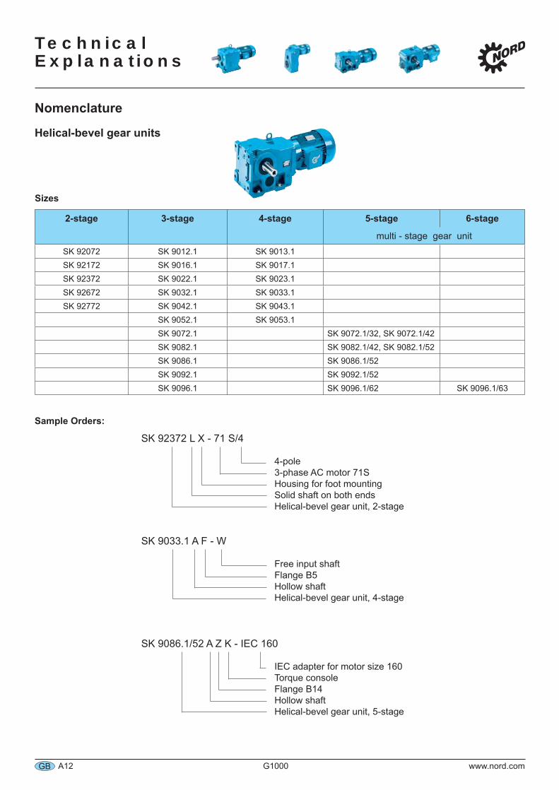
Nomenclature
Helical-bevel gear units
Sample Orders:
SK 92372 L X - 71 S/4
4-pole 3-phase AC motor 71S Housing for foot mounting Solid shaft on both ends Helical-bevel gear unit, 2-stage
SK 9033.1 A F - W
Free input shaft Flange B5 Hollow shaft Helical-bevel gear unit, 4-stage
SK 9086.1/52 A Z K - IEC 160
IEC adapter for motor size 160 Torque console Flange B14 Hollow shaft Helical-bevel gear unit, 5-stage
Sizes
2-stage 3-stage 4-stage 5-stage 6-stage
multi - stage gear unitSK 92072 SK 9012.1 SK 9013.1SK 92172 SK 9016.1 SK 9017.1SK 92372 SK 9022.1 SK 9023.1SK 92672 SK 9032.1 SK 9033.1SK 92772 SK 9042.1 SK 9043.1
SK 9052.1 SK 9053.1SK 9072.1 SK 9072.1/32, SK 9072.1/42SK 9082.1 SK 9082.1/42, SK 9082.1/52SK 9086.1 SK 9086.1/52SK 9092.1 SK 9092.1/52SK 9096.1 SK 9096.1/62 SK 9096.1/63
Technical
Explanations
www.nord.com G1000 A13 GB
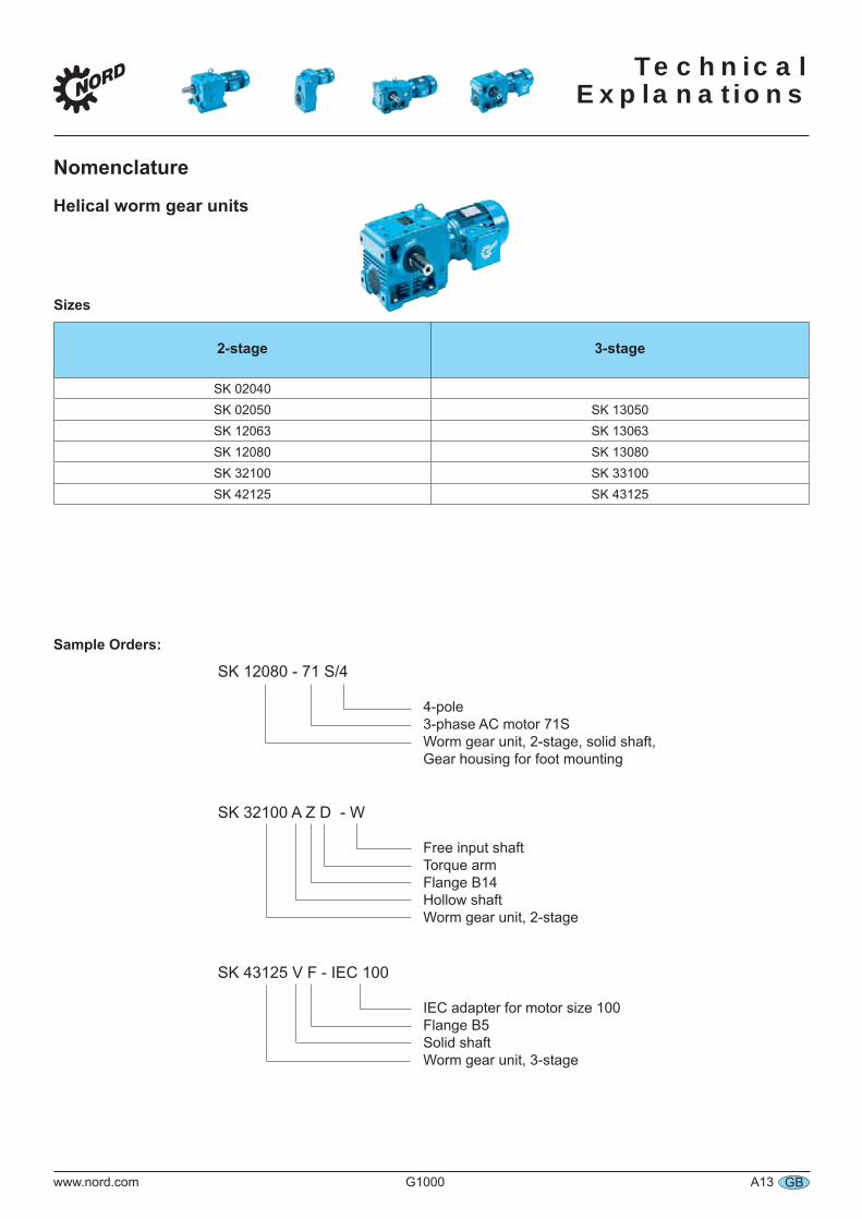
Sizes
2-stage 3-stage
SK 02040SK 02050 SK 13050SK 12063 SK 13063SK 12080 SK 13080SK 32100 SK 33100SK 42125 SK 43125
Sample Orders:
SK 12080 - 71 S/4
4-pole 3-phase AC motor 71S Worm gear unit, 2-stage, solid shaft, Gear housing for foot mounting
SK 32100 A Z D - W
Free input shaft Torque arm Flange B14 Hollow shaft Worm gear unit, 2-stage
SK 43125 V F - IEC 100
IEC adapter for motor size 100 Flange B5 Solid shaft Worm gear unit, 3-stage
Nomenclature
Helical worm gear units
Technical Explanations
A14 G1000 www.nord.comGB
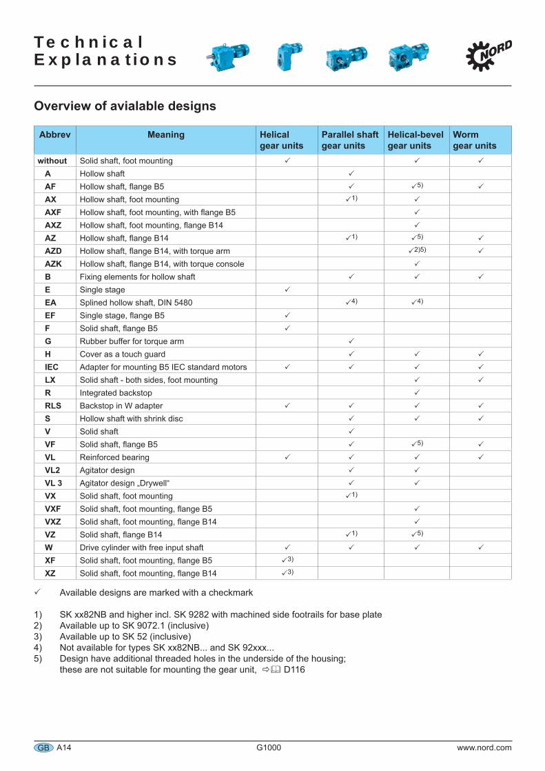
Overview of avialable designs
Abbrev Meaning Helicalgear units
Parallel shaft gear units
Helical-bevel gear units
Wormgear units
without Solid shaft, foot mountingA Hollow shaftAF Hollow shaft, flange B5 5)
AX Hollow shaft, foot mounting 1)
AXF Hollow shaft, foot mounting, with flange B5AXZ Hollow shaft, foot mounting, flange B14AZ Hollow shaft, flange B14 1) 5)
AZD Hollow shaft, flange B14, with torque arm 2)5)
AZK Hollow shaft, flange B14, with torque consoleB Fixing elements for hollow shaftE Single stageEA Splined hollow shaft, DIN 5480 4) 4)
EF Single stage, flange B5F Solid shaft, flange B5G Rubber buffer for torque armH Cover as a touch guardIEC Adapter for mounting B5 IEC standard motorsLX Solid shaft - both sides, foot mountingR Integrated backstopRLS Backstop in W adapterS Hollow shaft with shrink discV Solid shaftVF Solid shaft, flange B5 5)
VL Reinforced bearingVL2 Agitator designVL 3 Agitator design „Drywell“VX Solid shaft, foot mounting 1)
VXF Solid shaft, foot mounting, flange B5VXZ Solid shaft, foot mounting, flange B14VZ Solid shaft, flange B14 1) 5)
W Drive cylinder with free input shaftXF Solid shaft, foot mounting, flange B5 3)
XZ Solid shaft, foot mounting, flange B14 3)
Available designs are marked with a checkmark
1) SK xx82NB and higher incl. SK 9282 with machined side footrails for base plate2) Available up to SK 9072.1 (inclusive)3) Available up to SK 52 (inclusive)4) Not available for types SK xx82NB... and SK 92xxx...5) Design have additional threaded holes in the underside of the housing; these are not suitable for mounting the gear unit, D116
Technical
Explanations
www.nord.com G1000 A15 GB
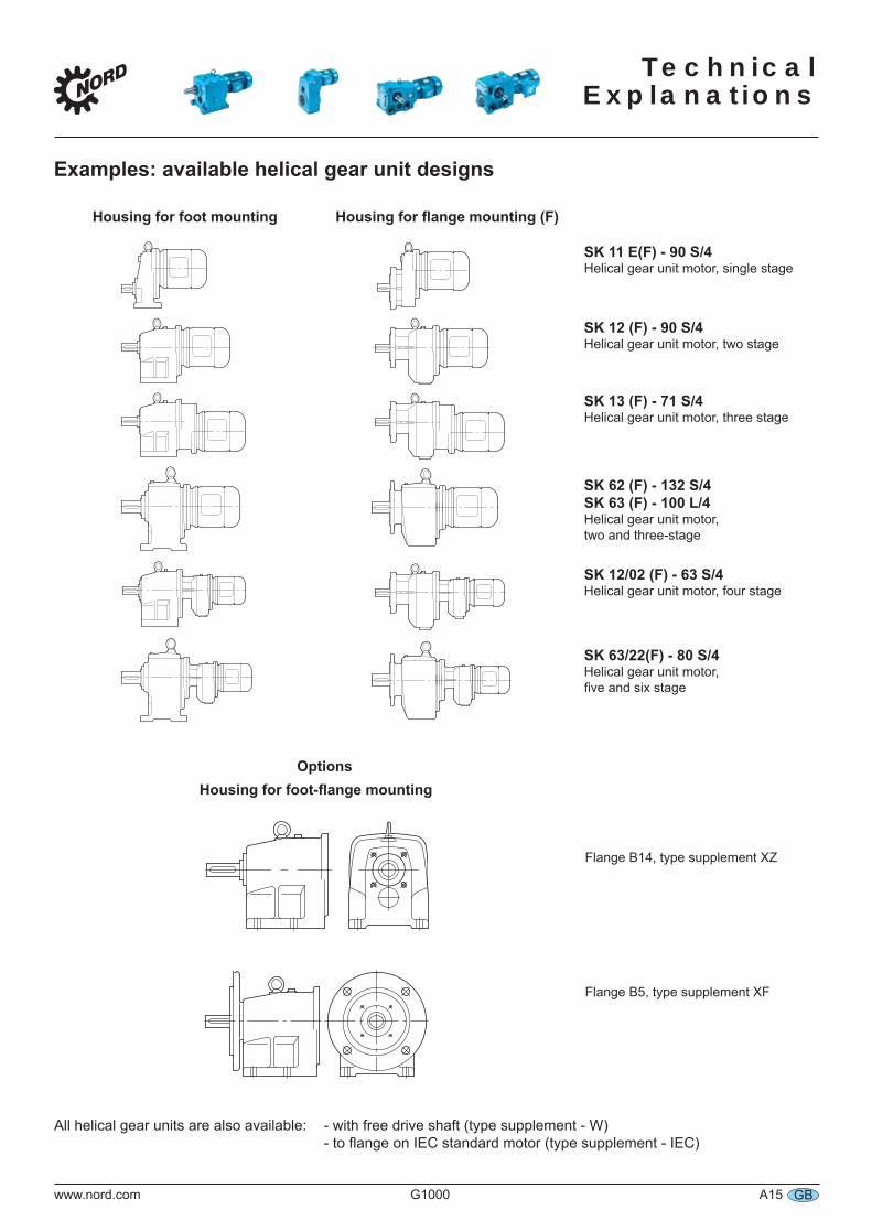
Examples: available helical gear unit designs
Housing for foot mounting Housing for flange mounting (F)
SK 11 E(F) - 90 S/4Helical gear unit motor, single stage
SK 12 (F) - 90 S/4Helical gear unit motor, two stage
SK 13 (F) - 71 S/4Helical gear unit motor, three stage
SK 62 (F) - 132 S/4SK 63 (F) - 100 L/4Helical gear unit motor, two and three-stage
SK 12/02 (F) - 63 S/4Helical gear unit motor, four stage
SK 63/22(F) - 80 S/4Helical gear unit motor, five and six stage
Flange B14, type supplement XZ
Flange B5, type supplement XF
All helical gear units are also available: - with free drive shaft (type supplement - W) - to flange on IEC standard motor (type supplement - IEC)
OptionsHousing for foot-flange mounting
Technical Explanations
A16 G1000 www.nord.comGB
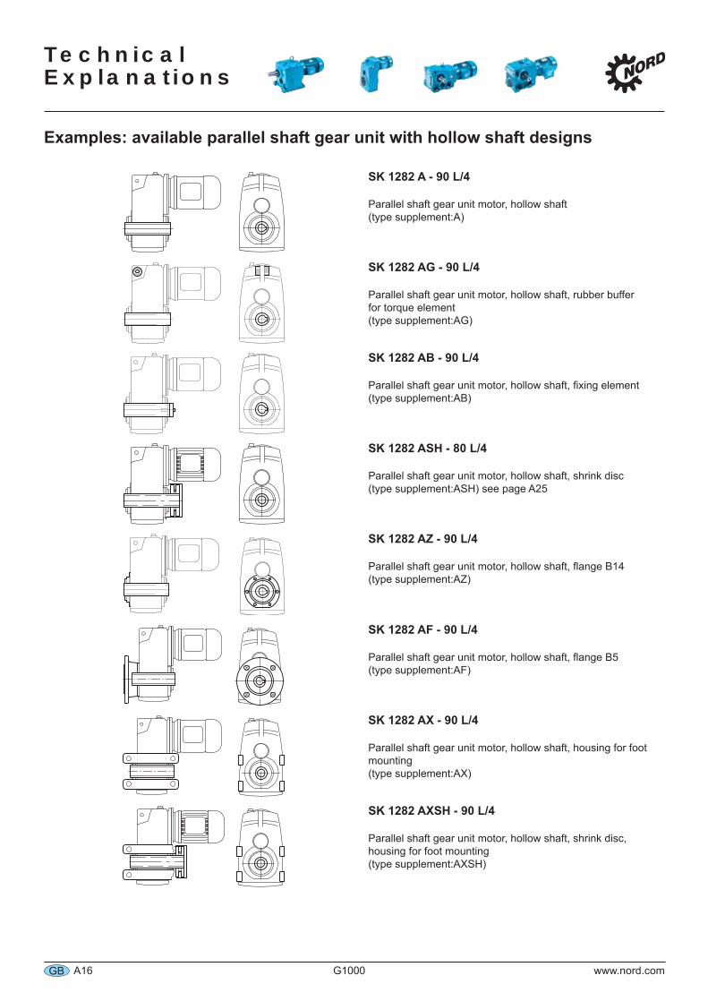
Examples: available parallel shaft gear unit with hollow shaft designs
SK 1282 A - 90 L/4
Parallel shaft gear unit motor, hollow shaft(type supplement:A)
SK 1282 AG - 90 L/4
Parallel shaft gear unit motor, hollow shaft, rubber buffer for torque element (type supplement:AG)
SK 1282 AB - 90 L/4
Parallel shaft gear unit motor, hollow shaft, fixing element(type supplement:AB)
SK 1282 ASH - 80 L/4
Parallel shaft gear unit motor, hollow shaft, shrink disc(type supplement:ASH) see page A25
SK 1282 AZ - 90 L/4
Parallel shaft gear unit motor, hollow shaft, flange B14(type supplement:AZ)
SK 1282 AF - 90 L/4
Parallel shaft gear unit motor, hollow shaft, flange B5(type supplement:AF)
SK 1282 AX - 90 L/4
Parallel shaft gear unit motor, hollow shaft, housing for foot mounting (type supplement:AX)
SK 1282 AXSH - 90 L/4
Parallel shaft gear unit motor, hollow shaft, shrink disc, housing for foot mounting (type supplement:AXSH)
Technical
Explanations
www.nord.com G1000 A17 GB
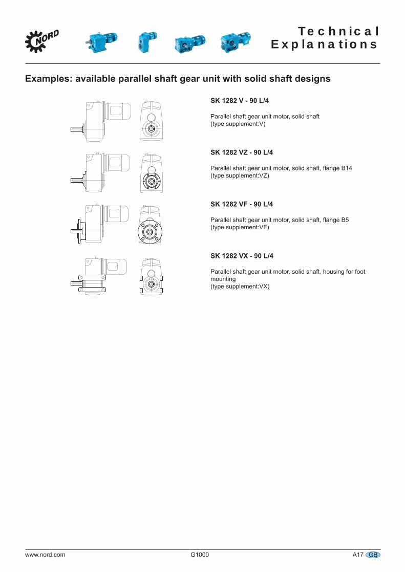
Examples: available parallel shaft gear unit with solid shaft designs
SK 1282 V - 90 L/4
Parallel shaft gear unit motor, solid shaft(type supplement:V)
SK 1282 VZ - 90 L/4
Parallel shaft gear unit motor, solid shaft, flange B14(type supplement:VZ)
SK 1282 VF - 90 L/4
Parallel shaft gear unit motor, solid shaft, flange B5(type supplement:VF)
SK 1282 VX - 90 L/4
Parallel shaft gear unit motor, solid shaft, housing for foot mounting (type supplement:VX)
Technical Explanations
A18 G1000 www.nord.comGB
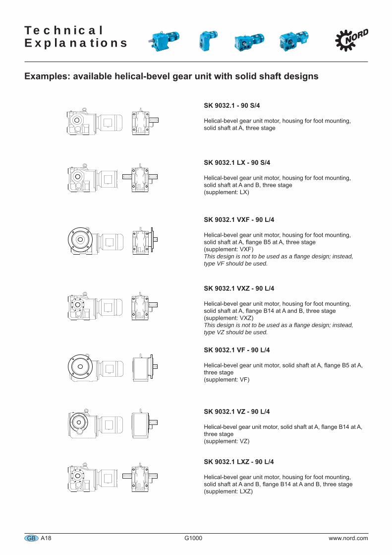
Examples: available helical-bevel gear unit with solid shaft designs
SK 9032.1 - 90 S/4
Helical-bevel gear unit motor, housing for foot mounting,solid shaft at A, three stage
SK 9032.1 LX - 90 S/4
Helical-bevel gear unit motor, housing for foot mounting,solid shaft at A and B, three stage (supplement: LX)
SK 9032.1 VXF - 90 L/4
Helical-bevel gear unit motor, housing for foot mounting,solid shaft at A, flange B5 at A, three stage (supplement: VXF)This design is not to be used as a flange design; instead, type VF should be used.
SK 9032.1 VXZ - 90 L/4
Helical-bevel gear unit motor, housing for foot mounting,solid shaft at A, flange B14 at A and B, three stage (supplement: VXZ)This design is not to be used as a flange design; instead, type VZ should be used.
SK 9032.1 VF - 90 L/4
Helical-bevel gear unit motor, solid shaft at A, flange B5 at A, three stage (supplement: VF)
SK 9032.1 VZ - 90 L/4
Helical-bevel gear unit motor, solid shaft at A, flange B14 at A, three stage (supplement: VZ)
SK 9032.1 LXZ - 90 L/4
Helical-bevel gear unit motor, housing for foot mounting, solid shaft at A and B, flange B14 at A and B, three stage (supplement: LXZ)
Technical
Explanations
www.nord.com G1000 A19 GB
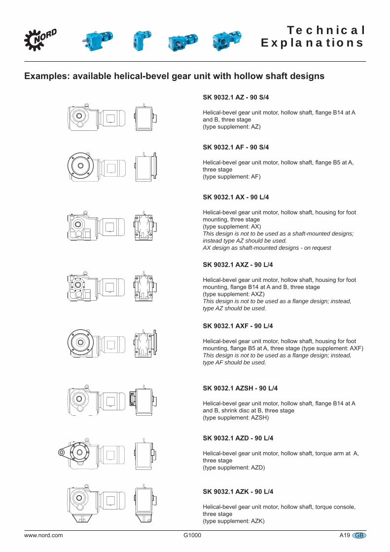
Examples: available helical-bevel gear unit with hollow shaft designs
SK 9032.1 AZ - 90 S/4
Helical-bevel gear unit motor, hollow shaft, flange B14 at A and B, three stage (type supplement: AZ)
SK 9032.1 AF - 90 S/4
Helical-bevel gear unit motor, hollow shaft, flange B5 at A, three stage (type supplement: AF)
SK 9032.1 AX - 90 L/4
Helical-bevel gear unit motor, hollow shaft, housing for foot mounting, three stage (type supplement: AX)This design is not to be used as a shaft-mounted designs; instead type AZ should be used.AX design as shaft-mounted designs - on request
SK 9032.1 AXZ - 90 L/4
Helical-bevel gear unit motor, hollow shaft, housing for foot mounting, flange B14 at A and B, three stage (type supplement: AXZ) This design is not to be used as a flange design; instead, type AZ should be used.
SK 9032.1 AXF - 90 L/4
Helical-bevel gear unit motor, hollow shaft, housing for foot mounting, flange B5 at A, three stage (type supplement: AXF) This design is not to be used as a flange design; instead, type AF should be used.
SK 9032.1 AZSH - 90 L/4
Helical-bevel gear unit motor, hollow shaft, flange B14 at A and B, shrink disc at B, three stage (type supplement: AZSH)
SK 9032.1 AZD - 90 L/4
Helical-bevel gear unit motor, hollow shaft, torque arm at A, three stage (type supplement: AZD)
SK 9032.1 AZK - 90 L/4
Helical-bevel gear unit motor, hollow shaft, torque console, three stage (type supplement: AZK)
Technical Explanations
A20 G1000 www.nord.comGB
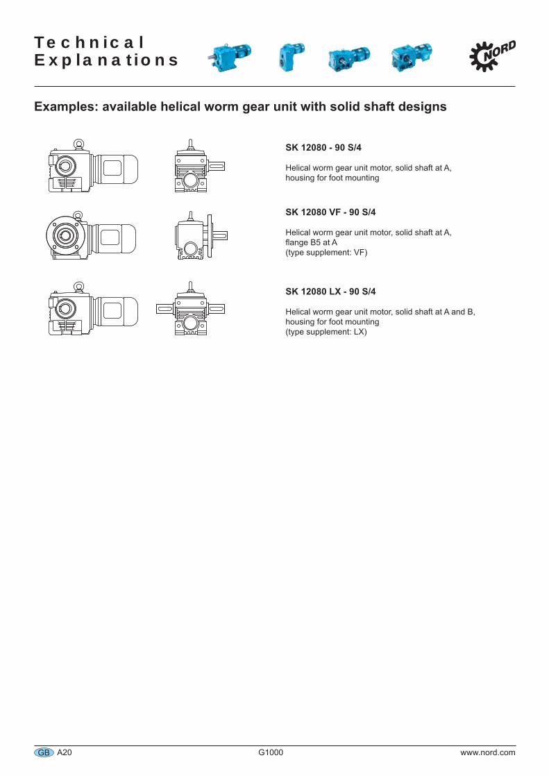
Examples: available helical worm gear unit with solid shaft designs
SK 12080 - 90 S/4
Helical worm gear unit motor, solid shaft at A, housing for foot mounting
SK 12080 VF - 90 S/4
Helical worm gear unit motor, solid shaft at A, flange B5 at A (type supplement: VF)
SK 12080 LX - 90 S/4
Helical worm gear unit motor, solid shaft at A and B, housing for foot mounting (type supplement: LX)
Technical
Explanations
www.nord.com G1000 A21 GB
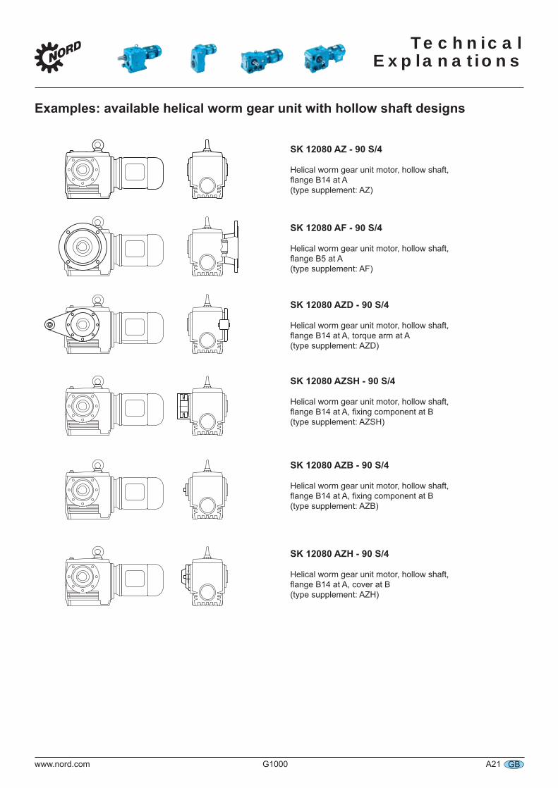
Examples: available helical worm gear unit with hollow shaft designs
SK 12080 AZ - 90 S/4
Helical worm gear unit motor, hollow shaft, flange B14 at A (type supplement: AZ)
SK 12080 AF - 90 S/4
Helical worm gear unit motor, hollow shaft, flange B5 at A (type supplement: AF)
SK 12080 AZD - 90 S/4
Helical worm gear unit motor, hollow shaft, flange B14 at A, torque arm at A (type supplement: AZD)
SK 12080 AZSH - 90 S/4
Helical worm gear unit motor, hollow shaft, flange B14 at A, fixing component at B (type supplement: AZSH)
SK 12080 AZB - 90 S/4
Helical worm gear unit motor, hollow shaft, flange B14 at A, fixing component at B(type supplement: AZB)
SK 12080 AZH - 90 S/4
Helical worm gear unit motor, hollow shaft, flange B14 at A, cover at B (type supplement: AZH)
Technical Explanations
A22 G1000 www.nord.comGB
Shrink discs
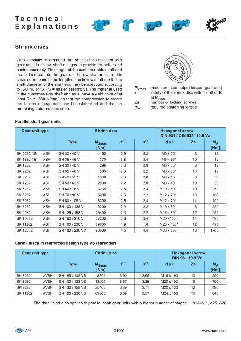
We especially recommend that shrink discs be used with gear units in hollow shaft designs to provide for better and easier assembly. The length of the customer-side shaft end that is inserted into the gear unit hollow shaft must, in this case, correspond to the length of the hollow shaft (mH). The shaft diameter of the shaft end may be executed according to ISO h6 or f6. (f6 = easier assembly). The material used in the customer-side shaft end must have a yield point of at least Re = 360 N/mm2 so that the compression to create the friction engagement can be established and that no remaining deformations arise.
M2max max. permitted output torque (gear unit)s safety of the shrink disc with fits h6 or f6 at M2maxZs number of locking screwsMA required tightening torque
Parallel shaft gear units
Gear unit type Shrink disc Hexagonal screwDIN 931 / DIN 933* 10.9 Vz
Type M2max[Nm]
sh6 sf6 d x l Zs MA[Nm]
SK 0282 NB ASH SN 30 / 40 V 165 5,9 5,2 M6 x 35* 8 12SK 1382 NB ASH SN 35 / 46 V 370 3,8 3,4 M6 x 35* 10 12SK 1282 ASH SN 30 / 40 V 296 3,3 2,9 M6 x 35* 8 12SK 2282 ASH SN 35 / 46 V 563 2,6 2,2 M6 x 35* 10 12SK 3282 ASH SN 40 / 55 V 1039 2,3 2,0 M8 x 40 8 30SK 4282 ASH SN 50 / 62 V 2000 2,2 2,0 M8 x 40 10 30SK 5282 ASH SN 60 / 76 V 3235 2,5 2,3 M10 x 50 10 59SK 6282 ASH SN 70 / 90 V 6000 2,3 2,2 M12 x 70* 10 100SK 7282 ASH SN 80 / 108 V 8300 2,5 2,4 M12 x 70* 14 100SK 8282 ASH SN 100 / 128 V 13200 2,3 2,2 M16 x 80* 8 250SK 9282 ASH SN 125 / 158 V 25400 2,3 2,2 M16 x 80* 12 250SK 10282 ASH SN 160 / 210 V 37200 3,6 3,4 M20 x100 14 490SK 11282 ASH SN 180 / 230 V 69000 1,9 1,8 M20 x 100* 12 490SK 12382 ASH SN 180 / 230 VV 90000 4,5 4,4 M30 x 200 16 1700
Shrink discs in reinforced design type VS (shredder)
Gear unit type Shrink disc Hexagonal screwDIN 931 10.9 Vz
Type M2max[Nm]
sh6 sf6 d x l Zs MA[Nm]
SK 7282 AVSH SN 85 / 108 VS 8300 3,90 3,65 M16 x 90 10 250SK 8282 AVSH SN 100 / 128 VS 13200 3,57 3,35 M20 x 100 8 490SK 9282 AVSH SN 130 / 158 VS 25400 3,89 3,71 M20 x 130 12 490SK 11282 AVSH SN 180 / 230 VS 69000 3,69 3,57 M24 x 150 16 840
The data listed also applies to parallel shaft gear units with a higher number of stages. A11, A25, A26
Technical
Explanations
www.nord.com G1000 A23 GB
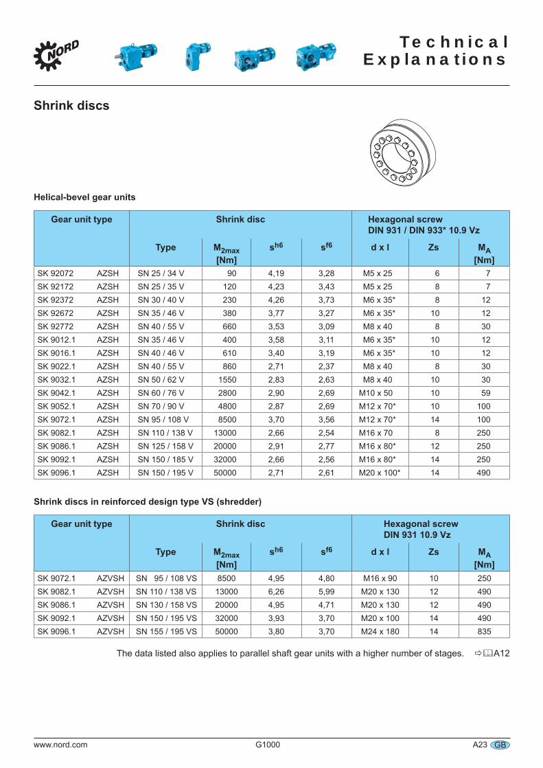
Shrink discs
Helical-bevel gear units
Gear unit type Shrink disc Hexagonal screwDIN 931 / DIN 933* 10.9 Vz
Type M2max[Nm]
sh6 sf6 d x l Zs MA[Nm]
SK 92072 AZSH SN 25 / 34 V 90 4,19 3,28 M5 x 25 6 7SK 92172 AZSH SN 25 / 35 V 120 4,23 3,43 M5 x 25 8 7SK 92372 AZSH SN 30 / 40 V 230 4,26 3,73 M6 x 35* 8 12SK 92672 AZSH SN 35 / 46 V 380 3,77 3,27 M6 x 35* 10 12SK 92772 AZSH SN 40 / 55 V 660 3,53 3,09 M8 x 40 8 30SK 9012.1 AZSH SN 35 / 46 V 400 3,58 3,11 M6 x 35* 10 12SK 9016.1 AZSH SN 40 / 46 V 610 3,40 3,19 M6 x 35* 10 12SK 9022.1 AZSH SN 40 / 55 V 860 2,71 2,37 M8 x 40 8 30SK 9032.1 AZSH SN 50 / 62 V 1550 2,83 2,63 M8 x 40 10 30SK 9042.1 AZSH SN 60 / 76 V 2800 2,90 2,69 M10 x 50 10 59SK 9052.1 AZSH SN 70 / 90 V 4800 2,87 2,69 M12 x 70* 10 100SK 9072.1 AZSH SN 95 / 108 V 8500 3,70 3,56 M12 x 70* 14 100SK 9082.1 AZSH SN 110 / 138 V 13000 2,66 2,54 M16 x 70 8 250SK 9086.1 AZSH SN 125 / 158 V 20000 2,91 2,77 M16 x 80* 12 250SK 9092.1 AZSH SN 150 / 185 V 32000 2,66 2,56 M16 x 80* 14 250SK 9096.1 AZSH SN 150 / 195 V 50000 2,71 2,61 M20 x 100* 14 490
Shrink discs in reinforced design type VS (shredder)
Gear unit type Shrink disc Hexagonal screwDIN 931 10.9 Vz
Type M2max[Nm]
sh6 sf6 d x l Zs MA[Nm]
SK 9072.1 AZVSH SN 95 / 108 VS 8500 4,95 4,80 M16 x 90 10 250SK 9082.1 AZVSH SN 110 / 138 VS 13000 6,26 5,99 M20 x 130 12 490SK 9086.1 AZVSH SN 130 / 158 VS 20000 4,95 4,71 M20 x 130 12 490SK 9092.1 AZVSH SN 150 / 195 VS 32000 3,93 3,70 M20 x 100 14 490SK 9096.1 AZVSH SN 155 / 195 VS 50000 3,80 3,70 M24 x 180 14 835
The data listed also applies to parallel shaft gear units with a higher number of stages. A12
Technical Explanations
A24 G1000 www.nord.comGB
Shrink discs
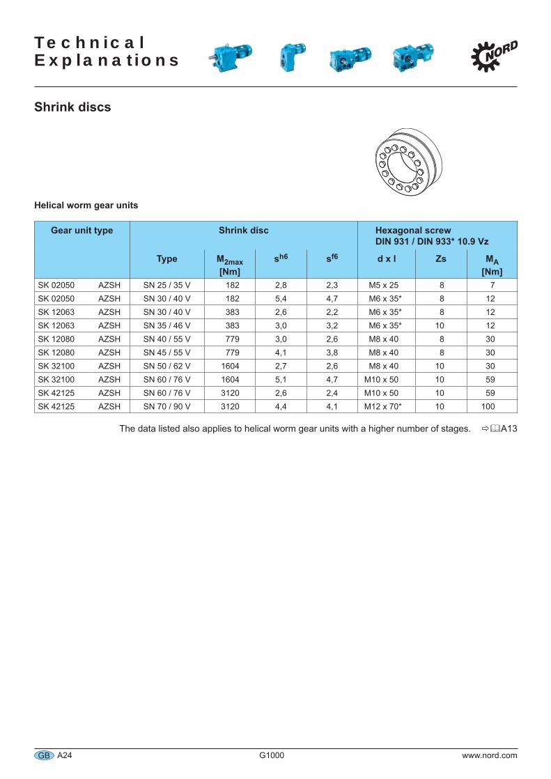
Helical worm gear units
Gear unit type Shrink disc Hexagonal screwDIN 931 / DIN 933* 10.9 Vz
Type M2max[Nm]
sh6 sf6 d x l Zs MA[Nm]
SK 02050 AZSH SN 25 / 35 V 182 2,8 2,3 M5 x 25 8 7SK 02050 AZSH SN 30 / 40 V 182 5,4 4,7 M6 x 35* 8 12SK 12063 AZSH SN 30 / 40 V 383 2,6 2,2 M6 x 35* 8 12SK 12063 AZSH SN 35 / 46 V 383 3,0 3,2 M6 x 35* 10 12SK 12080 AZSH SN 40 / 55 V 779 3,0 2,6 M8 x 40 8 30SK 12080 AZSH SN 45 / 55 V 779 4,1 3,8 M8 x 40 8 30SK 32100 AZSH SN 50 / 62 V 1604 2,7 2,6 M8 x 40 10 30SK 32100 AZSH SN 60 / 76 V 1604 5,1 4,7 M10 x 50 10 59SK 42125 AZSH SN 60 / 76 V 3120 2,6 2,4 M10 x 50 10 59SK 42125 AZSH SN 70 / 90 V 3120 4,4 4,1 M12 x 70* 10 100
The data listed also applies to helical worm gear units with a higher number of stages. A13
Technical
Explanations
www.nord.com G1000 A25 GB
Shrink discs
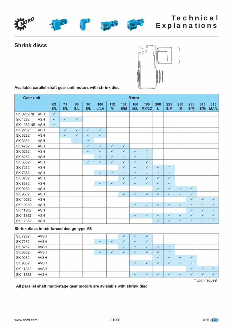
Available parallel shaft gear unit motors with shrink disc
Gear unit Motor63 S/L
71 S/L
80 S/L
90 S/L
100 L/LA
112 M
132S/M
160 M/L
180 MX/LX
200 L
225 S/M
250 M
280 S/M
315 S/M
315 MA/L
SK 0282 NB ASHSK 1282 ASHSK 1382 NB ASHSK 2282 ASHSK 3282 ASHSK 3382 ASHSK 4282 ASHSK 5282 ASH *
SK 6282 ASHSK 6382 ASHSK 7282 ASH *
SK 7382 ASH *
SK 8282 ASHSK 8382 ASHSK 9282 ASHSK 9382 ASHSK 10282 ASHSK 10382 ASHSK 11282 ASHSK 11382 ASHSK 12382 ASH
Shrink discs in reinforced design type VS
SK 7282 AVSHSK 7382 AVSHSK 8282 AVSH *
SK 8382 AVSH *
SK 9282 AVSHSK 9382 AVSHSK 11282 AVSHSK 11382 AVSH
* upon request
All parallel shaft multi-stage gear motors are avialable with shrink disc
Technical Explanations
A26 G1000 www.nord.comGB
Shrink discs
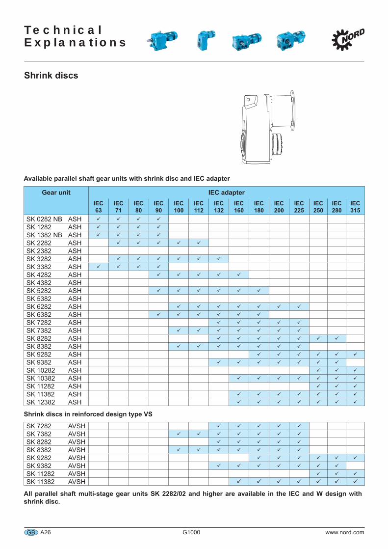
Available parallel shaft gear units with shrink disc and IEC adapter
Gear unit IEC adapterIEC 63
IEC 71
IEC 80
IEC 90
IEC 100
IEC 112
IEC 132
IEC 160
IEC 180
IEC 200
IEC 225
IEC 250
IEC 280
IEC 315
SK 0282 NB ASHSK 1282 ASHSK 1382 NB ASHSK 2282 ASHSK 2382 ASHSK 3282 ASHSK 3382 ASHSK 4282 ASHSK 4382 ASHSK 5282 ASHSK 5382 ASHSK 6282 ASHSK 6382 ASHSK 7282 ASHSK 7382 ASHSK 8282 ASHSK 8382 ASHSK 9282 ASHSK 9382 ASHSK 10282 ASHSK 10382 ASHSK 11282 ASHSK 11382 ASHSK 12382 ASH
Shrink discs in reinforced design type VS
SK 7282 AVSHSK 7382 AVSHSK 8282 AVSHSK 8382 AVSHSK 9282 AVSHSK 9382 AVSHSK 11282 AVSHSK 11382 AVSH
All parallel shaft multi-stage gear units SK 2282/02 and higher are available in the IEC and W design with shrink disc.
Technical
Explanations
www.nord.com G1000 A27 GB
Fixing elements
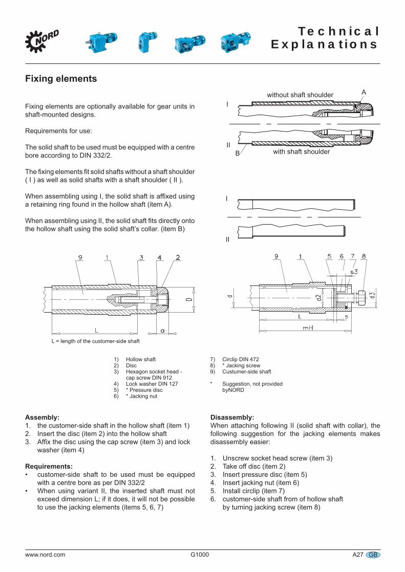
Fixing elements are optionally available for gear units in shaft-mounted designs.
Requirements for use:
The solid shaft to be used must be equipped with a centre bore according to DIN 332/2.
The fixing elements fit solid shafts without a shaft shoulder ( I ) as well as solid shafts with a shaft shoulder ( II ).
When assembling using I, the solid shaft is affixed using a retaining ring found in the hollow shaft (item A).
When assembling using II, the solid shaft fits directly onto the hollow shaft using the solid shaft’s collar. (item B)
without shaft shoulder A
B
I
II
I
II
with shaft shoulder
L = length of the customer-side shaft
1) Hollow shaft2) Disc3) Hexagon socket head - cap screw DIN 9124) Lock washer DIN 1275) * Pressure disc6) * Jacking nut
7) Circlip DIN 4728) * Jacking screw9) Custumer-side shaft
* Suggestion, not provided byNORD
Assembly:1. the customer-side shaft in the hollow shaft (item 1)2. Insert the disc (item 2) into the hollow shaft3. Affix the disc using the cap screw (item 3) and lock washer (item 4)
Requirements:customer-side shaft to be used must be equipped with a centre bore as per DIN 332/2When using variant II, the inserted shaft must not exceed dimension L; if it does, it will not be possible to use the jacking elements (items 5, 6, 7)
•
•
Disassembly:When attaching following II (solid shaft with collar), the following suggestion for the jacking elements makes disassembly easier:
1. Unscrew socket head screw (item 3)2. Take off disc (item 2)3. Insert pressure disc (item 5)4. Insert jacking nut (item 6)5. Install circlip (item 7)6. customer-side shaft from of hollow shaft by turning jacking screw (item 8)
Technical Explanations
A28 G1000 www.nord.comGB
Fixing elements
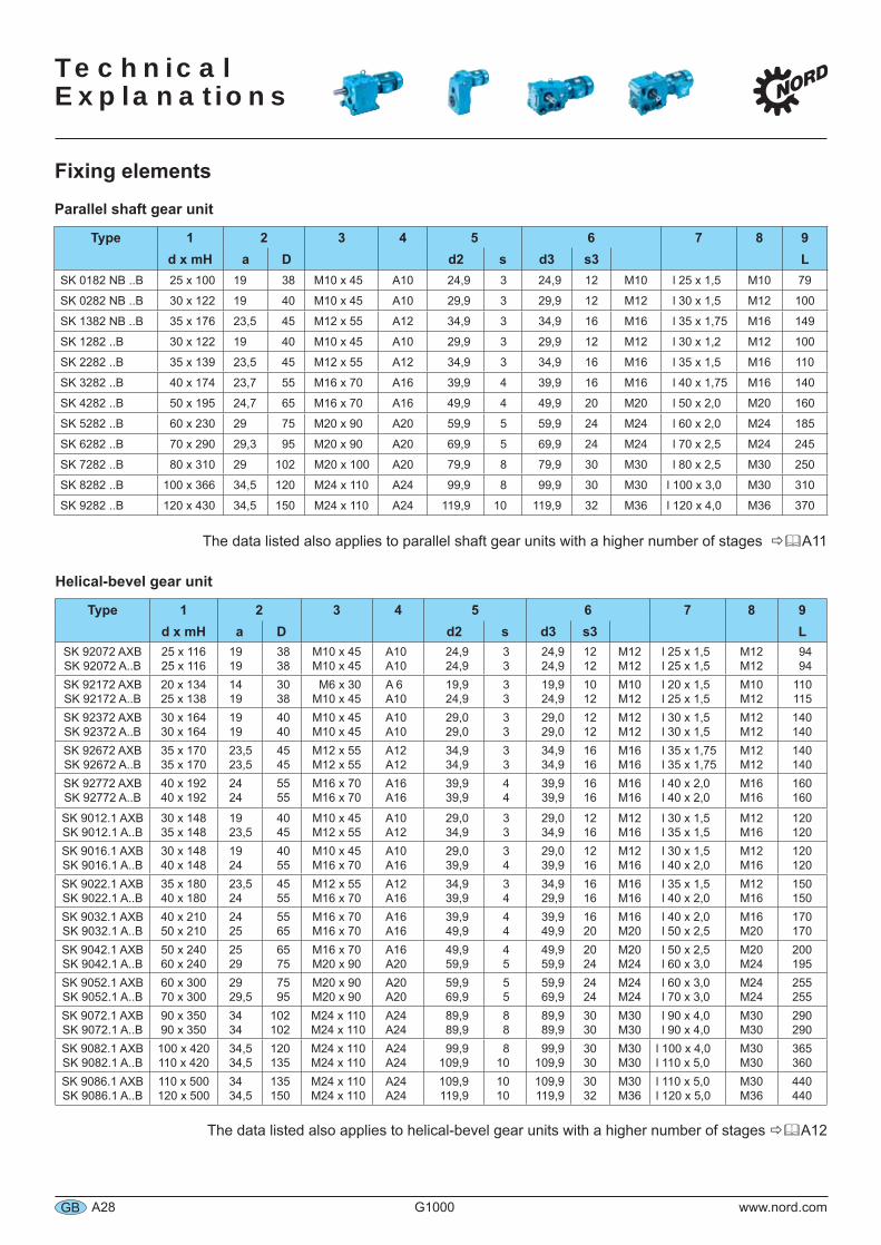
Parallel shaft gear unit
Type 1 2 3 4 5 6 7 8 9d x mH a D d2 s d3 s3 L
SK 0182 NB ..B 25 x 100 19 38 M10 x 45 A10 24,9 3 24,9 12 M10 l 25 x 1,5 M10 79
SK 0282 NB ..B 30 x 122 19 40 M10 x 45 A10 29,9 3 29,9 12 M12 l 30 x 1,5 M12 100
SK 1382 NB ..B 35 x 176 23,5 45 M12 x 55 A12 34,9 3 34,9 16 M16 l 35 x 1,75 M16 149
SK 1282 ..B 30 x 122 19 40 M10 x 45 A10 29,9 3 29,9 12 M12 l 30 x 1,2 M12 100
SK 2282 ..B 35 x 139 23,5 45 M12 x 55 A12 34,9 3 34,9 16 M16 l 35 x 1,5 M16 110
SK 3282 ..B 40 x 174 23,7 55 M16 x 70 A16 39,9 4 39,9 16 M16 l 40 x 1,75 M16 140
SK 4282 ..B 50 x 195 24,7 65 M16 x 70 A16 49,9 4 49,9 20 M20 l 50 x 2,0 M20 160
SK 5282 ..B 60 x 230 29 75 M20 x 90 A20 59,9 5 59,9 24 M24 l 60 x 2,0 M24 185
SK 6282 ..B 70 x 290 29,3 95 M20 x 90 A20 69,9 5 69,9 24 M24 l 70 x 2,5 M24 245
SK 7282 ..B 80 x 310 29 102 M20 x 100 A20 79,9 8 79,9 30 M30 l 80 x 2,5 M30 250
SK 8282 ..B 100 x 366 34,5 120 M24 x 110 A24 99,9 8 99,9 30 M30 l 100 x 3,0 M30 310
SK 9282 ..B 120 x 430 34,5 150 M24 x 110 A24 119,9 10 119,9 32 M36 l 120 x 4,0 M36 370
The data listed also applies to parallel shaft gear units with a higher number of stages A11
Helical-bevel gear unit
Type 1 2 3 4 5 6 7 8 9d x mH a D d2 s d3 s3 L
SK 92072 AXBSK 92072 A..B
25 x 11625 x 116
1919
3838
M10 x 45M10 x 45
A10A10
24,924,9
33
24,924,9
1212
M12M12
l 25 x 1,5l 25 x 1,5
M12M12
9494
SK 92172 AXBSK 92172 A..B
20 x 13425 x 138
1419
3038
M6 x 30M10 x 45
A 6A10
19,924,9
33
19,924,9
1012
M10M12
l 20 x 1,5l 25 x 1,5
M10M12
110115
SK 92372 AXBSK 92372 A..B
30 x 16430 x 164
1919
4040
M10 x 45M10 x 45
A10A10
29,029,0
33
29,029,0
1212
M12M12
l 30 x 1,5l 30 x 1,5
M12M12
140140
SK 92672 AXBSK 92672 A..B
35 x 17035 x 170
23,523,5
4545
M12 x 55M12 x 55
A12A12
34,934,9
33
34,934,9
1616
M16M16
l 35 x 1,75l 35 x 1,75
M12M12
140140
SK 92772 AXBSK 92772 A..B
40 x 19240 x 192
2424
5555
M16 x 70M16 x 70
A16A16
39,939,9
44
39,939,9
1616
M16M16
l 40 x 2,0l 40 x 2,0
M16M16
160160
SK 9012.1 AXBSK 9012.1 A..B
30 x 14835 x 148
1923,5
4045
M10 x 45M12 x 55
A10A12
29,034,9
33
29,034,9
1216
M12M16
l 30 x 1,5l 35 x 1,5
M12M16
120120
SK 9016.1 AXBSK 9016.1 A..B
30 x 14840 x 148
1924
4055
M10 x 45M16 x 70
A10A16
29,039,9
34
29,039,9
1216
M12M16
l 30 x 1,5l 40 x 2,0
M12M16
120120
SK 9022.1 AXBSK 9022.1 A..B
35 x 18040 x 180
23,524
4555
M12 x 55M16 x 70
A12A16
34,939,9
34
34,929,9
1616
M16M16
l 35 x 1,5l 40 x 2,0
M12M16
150150
SK 9032.1 AXBSK 9032.1 A..B
40 x 21050 x 210
2425
5565
M16 x 70M16 x 70
A16A16
39,949,9
44
39,949,9
1620
M16M20
l 40 x 2,0l 50 x 2,5
M16M20
170170
SK 9042.1 AXBSK 9042.1 A..B
50 x 24060 x 240
2529
6575
M16 x 70M20 x 90
A16A20
49,959,9
45
49,959,9
2024
M20M24
l 50 x 2,5l 60 x 3,0
M20M24
200195
SK 9052.1 AXBSK 9052.1 A..B
60 x 30070 x 300
2929,5
7595
M20 x 90M20 x 90
A20A20
59,969,9
55
59,969,9
2424
M24M24
l 60 x 3,0l 70 x 3,0
M24M24
255255
SK 9072.1 AXBSK 9072.1 A..B
90 x 35090 x 350
3434
102102
M24 x 110 M24 x 110
A24A24
89,989,9
88
89,989,9
3030
M30M30
l 90 x 4,0l 90 x 4,0
M30M30
290290
SK 9082.1 AXBSK 9082.1 A..B
100 x 420110 x 420
34,534,5
120135
M24 x 110 M24 x 110
A24A24
99,9109,9
810
99,9109,9
3030
M30M30
l 100 x 4,0l 110 x 5,0
M30M30
365360
SK 9086.1 AXBSK 9086.1 A..B
110 x 500120 x 500
3434,5
135150
M24 x 110 M24 x 110
A24A24
109,9119,9
1010
109,9119,9
3032
M30M36
l 110 x 5,0l 120 x 5,0
M30M36
440440
The data listed also applies to helical-bevel gear units with a higher number of stages A12
Technical
Explanations
www.nord.com G1000 A29 GB
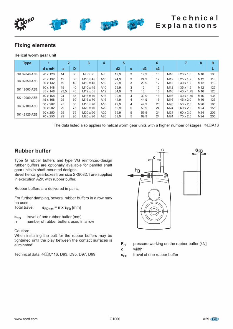
Rubber bufferType G rubber buffers and type VG reinforced-design rubber buffers are optionally available for parallel shaft gear units in shaft-mounted designs.Bevel helical gearboxes from size SK9082.1 are supplied in execution AZK with rubber buffer.
Rubber buffers are delivered in pairs.
For further damping, several rubber buffers in a row may be used.Total travel: sFD tot = n x sFD [mm]
sFD travel of one rubber buffer [mm]n number of rubber buffers used in a row
FD pressure working on the rubber buffer [kN]c widthsFD travel of one rubber buffer
Fixing elements
Helical worm gear unit
Type 1 2 3 4 5 6 7 8 9d x mH a D d2 s d3 s3 L
SK 02040 AZB 20 x 120 14 30 M6 x 30 A 6 19,9 3 19,9 10 M10 l 20 x 1,5 M10 100
SK 02050 AZB 25 x 13230 x 132
1919
3840
M10 x 45M10 x 45
A10A10
24,929,9
33
24,929,9
1212
M12M12
l 25 x 1,2l 30 x 1,2
M12M12
110110
SK 12063 AZB 30 x 14835 x 148
1923,5
4045
M10 x 45M12 x 55
A10A12
29,934,9
33
1216
1216
M12M16
l 35 x 1,5l 40 x 1,75
M12M16
125120
SK 12080 AZB 40 x 16845 x 168
2425
5560
M16 x 70M16 x 70
A16A16
39,944,9
44
39,944,9
1616
M16M16
l 40 x 1,75l 45 x 2,0
M16M16
135135
SK 32100 AZB 50 x 20260 x 202
2529
6575
M16 x 70M20 x 70
A16A20
49,959,9
45
49,959,9
2024
M20M24
l 50 x 2,0l 60 x 2,0
M20M24
165155
SK 42125 AZB 60 x 25070 x 250
2929
7595
M20 x 90M20 x 90
A20A20
59,969,9
55
59,969,9
2424
M24M24
l 60 x 2,0l 70 x 2,5
M24M24
205205
The data listed also applies to helical worm gear units with a higher number of stages A13
Caution:When installing the bolt for the rubber buffers may betightened until the play between the contact surfaces iseliminated!
Technical data C116, D93, D95, D97, D99
Technical Explanations
A30 G1000 www.nord.comGB
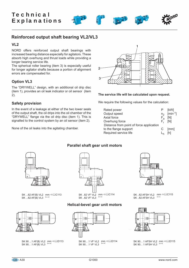
VL2NORD offers reinforced output shaft bearings with increased bearing distance especially for agitators. These absorb high overhung and thrust loads while providing a longer bearing service life. The spherical roller bearing (item 3) is especially useful for longer agitator shafts because a portion of alignment errors are compensated for.
Option VL3The “DRYWELL” design, with an additional oil drip disc (item 1), provides an oil leak indicator or oil sensor (item 2).
Safety provisionIn the event of a leakage at either of the two lower seals of the output shaft, the oil drips into the oil chamber of the “DRYWELL” flange via the oil drip disc (item 1). This is signalled to the control system by an oil sensor (item 2).
None of the oil leaks into the agitating chamber.
The service life will be calculated upon request.
We require the following values for the calculation:
Rated power P [kW] Output speed n2 [min-1] Axial force Fa [N] Overhung force Fr [N] Distance from point of force application to the flange support C [mm] Required service life Lh [h]
11
22
33
Reinforced output shaft bearing VL2/VL3
Parallel shaft gear unit motors
SK ...82 AF(B) VL2SK ...82 AF(B) VL3
SK ..82 VF VL2SK ..82 VF VL3
SK ..82 AFSH VL2SK ..82 AFSH VL3
Helical-bevel gear unit motors
SK 90 ...1 AF(B) VL2SK 90.. .1 AF(B) VL3
SK 90.. .1 VF VL2SK 90.. .1 VF VL3
SK 90.. .1 AFSH VL2SK 90.. .1 AFSH VL3
mm C114
mm D113
mm C113 mm C115
mm D114 mm D115
Technical
Explanations
www.nord.com G1000 A31 GB
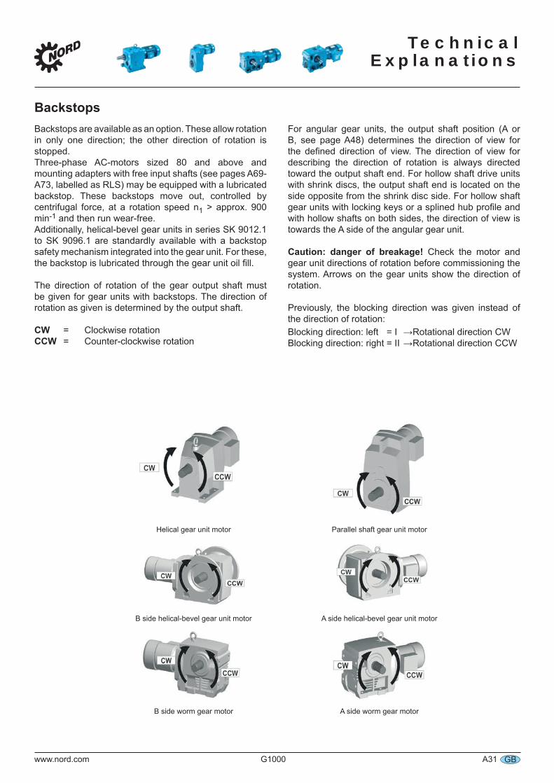
Backstops are available as an option. These allow rotation in only one direction; the other direction of rotation is stopped.Three-phase AC-motors sized 80 and above and mounting adapters with free input shafts (see pages A69-A73, labelled as RLS) may be equipped with a lubricated backstop. These backstops move out, controlled by centrifugal force, at a rotation speed n1 > approx. 900 min-1 and then run wear-free.Additionally, helical-bevel gear units in series SK 9012.1 to SK 9096.1 are standardly available with a backstop safety mechanism integrated into the gear unit. For these, the backstop is lubricated through the gear unit oil fill.
The direction of rotation of the gear output shaft must be given for gear units with backstops. The direction of rotation as given is determined by the output shaft.
CW = Clockwise rotationCCW = Counter-clockwise rotation
For angular gear units, the output shaft position (A or B, see page A48) determines the direction of view for the defined direction of view. The direction of view for describing the direction of rotation is always directed toward the output shaft end. For hollow shaft drive units with shrink discs, the output shaft end is located on the side opposite from the shrink disc side. For hollow shaft gear units with locking keys or a splined hub profile and with hollow shafts on both sides, the direction of view is towards the A side of the angular gear unit.
Caution: danger of breakage! Check the motor and gear unit directions of rotation before commissioning the system. Arrows on the gear units show the direction of rotation.
Previously, the blocking direction was given instead of the direction of rotation:Blocking direction: left = I →Rotational direction CWBlocking direction: right = II →Rotational direction CCW
Helical gear unit motor Parallel shaft gear unit motor
B side helical-bevel gear unit motor A side helical-bevel gear unit motor
B side worm gear motor A side worm gear motor
Backstops
Technical Explanations
A32 G1000 www.nord.comGB
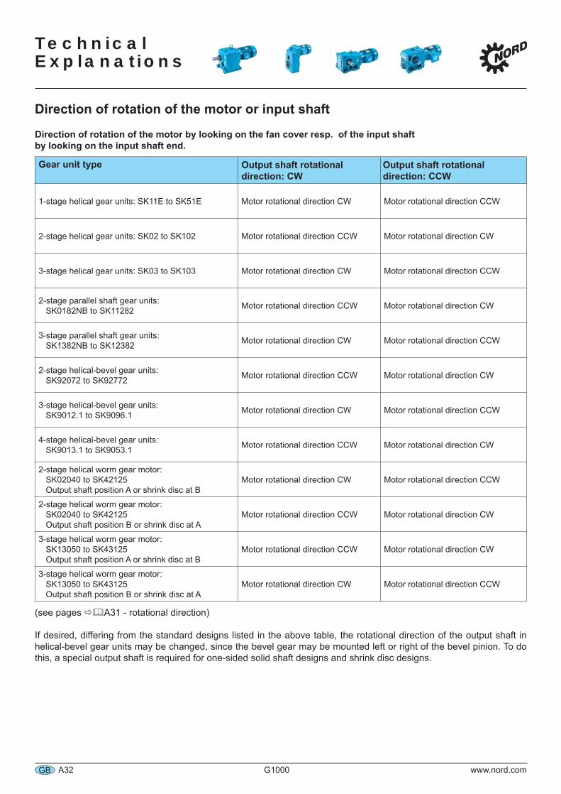
Direction of rotation of the motor or input shaft
Direction of rotation of the motor by looking on the fan cover resp. of the input shaft by looking on the input shaft end.
Gear unit type Output shaft rotational direction: CW
Output shaft rotational direction: CCW
1-stage helical gear units: SK11E to SK51E Motor rotational direction CW Motor rotational direction CCW
2-stage helical gear units: SK02 to SK102 Motor rotational direction CCW Motor rotational direction CW
3-stage helical gear units: SK03 to SK103 Motor rotational direction CW Motor rotational direction CCW
2-stage parallel shaft gear units: SK0182NB to SK11282 Motor rotational direction CCW Motor rotational direction CW
3-stage parallel shaft gear units: SK1382NB to SK12382 Motor rotational direction CW Motor rotational direction CCW
2-stage helical-bevel gear units: SK92072 to SK92772 Motor rotational direction CCW Motor rotational direction CW
3-stage helical-bevel gear units:SK9012.1 to SK9096.1 Motor rotational direction CW Motor rotational direction CCW
4-stage helical-bevel gear units:SK9013.1 to SK9053.1 Motor rotational direction CCW Motor rotational direction CW
2-stage helical worm gear motor:SK02040 to SK42125Output shaft position A or shrink disc at B
Motor rotational direction CW Motor rotational direction CCW
2-stage helical worm gear motor:SK02040 to SK42125Output shaft position B or shrink disc at A
Motor rotational direction CCW Motor rotational direction CW
3-stage helical worm gear motor:SK13050 to SK43125Output shaft position A or shrink disc at B
Motor rotational direction CCW Motor rotational direction CW
3-stage helical worm gear motor:SK13050 to SK43125Output shaft position B or shrink disc at A
Motor rotational direction CW Motor rotational direction CCW
(see pages A31 - rotational direction)
If desired, differing from the standard designs listed in the above table, the rotational direction of the output shaft in helical-bevel gear units may be changed, since the bevel gear may be mounted left or right of the bevel pinion. To do this, a special output shaft is required for one-sided solid shaft designs and shrink disc designs.
Technical
Explanations
www.nord.com G1000 A33 GB
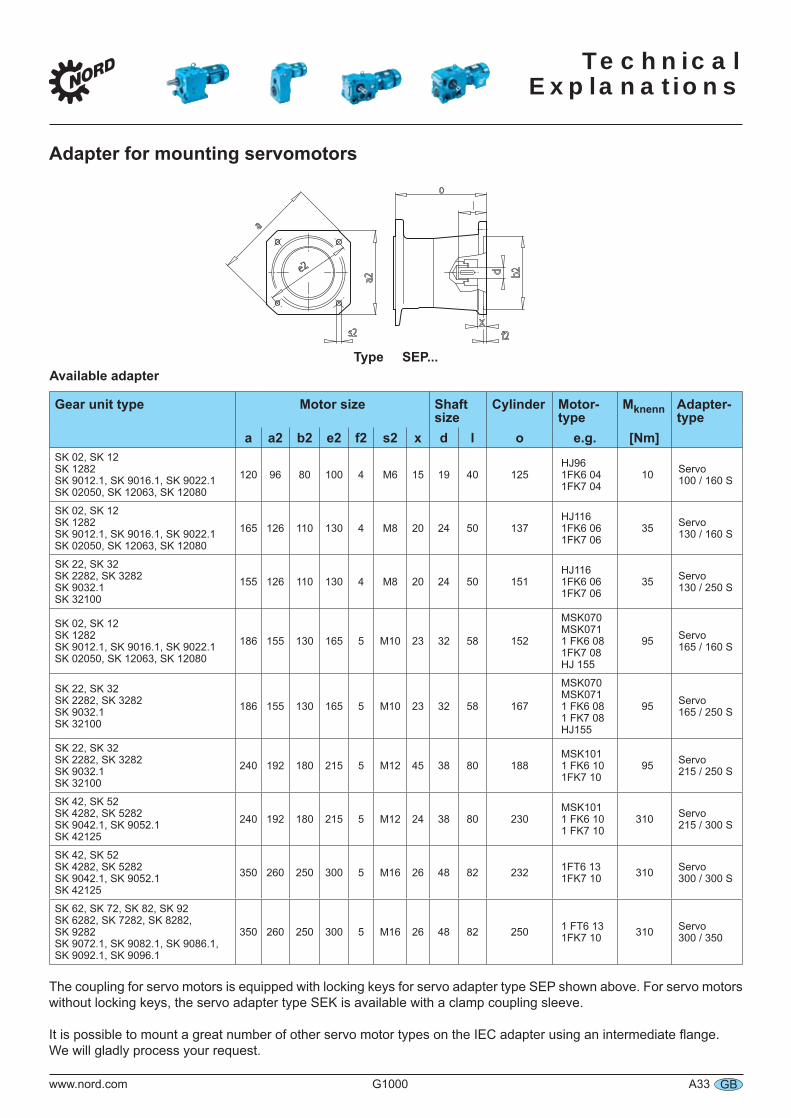
Adapter for mounting servomotors
Type SEP...Available adapter
Gear unit type Motor size Shaft size
Cylinder Motor-type
Mknenn Adapter- type
a a2 b2 e2 f2 s2 x d l o e.g. [Nm]SK 02, SK 12SK 1282SK 9012.1, SK 9016.1, SK 9022.1SK 02050, SK 12063, SK 12080
120 96 80 100 4 M6 15 19 40 125HJ961FK6 041FK7 04
10 Servo 100 / 160 S
SK 02, SK 12SK 1282SK 9012.1, SK 9016.1, SK 9022.1SK 02050, SK 12063, SK 12080
165 126 110 130 4 M8 20 24 50 137HJ1161FK6 061FK7 06
35 Servo 130 / 160 S
SK 22, SK 32SK 2282, SK 3282SK 9032.1SK 32100
155 126 110 130 4 M8 20 24 50 151HJ1161FK6 061FK7 06
35 Servo 130 / 250 S
SK 02, SK 12SK 1282SK 9012.1, SK 9016.1, SK 9022.1SK 02050, SK 12063, SK 12080
186 155 130 165 5 M10 23 32 58 152
MSK070MSK0711 FK6 081FK7 08HJ 155
95 Servo 165 / 160 S
SK 22, SK 32SK 2282, SK 3282SK 9032.1SK 32100
186 155 130 165 5 M10 23 32 58 167
MSK070MSK0711 FK6 081 FK7 08HJ155
95 Servo 165 / 250 S
SK 22, SK 32SK 2282, SK 3282SK 9032.1SK 32100
240 192 180 215 5 M12 45 38 80 188MSK1011 FK6 101FK7 10
95 Servo 215 / 250 S
SK 42, SK 52SK 4282, SK 5282SK 9042.1, SK 9052.1SK 42125
240 192 180 215 5 M12 24 38 80 230MSK1011 FK6 101 FK7 10
310 Servo215 / 300 S
SK 42, SK 52SK 4282, SK 5282SK 9042.1, SK 9052.1SK 42125
350 260 250 300 5 M16 26 48 82 232 1FT6 131FK7 10 310 Servo
300 / 300 S
SK 62, SK 72, SK 82, SK 92SK 6282, SK 7282, SK 8282, SK 9282SK 9072.1, SK 9082.1, SK 9086.1, SK 9092.1, SK 9096.1
350 260 250 300 5 M16 26 48 82 250 1 FT6 131FK7 10 310 Servo
300 / 350
The coupling for servo motors is equipped with locking keys for servo adapter type SEP shown above. For servo motors without locking keys, the servo adapter type SEK is available with a clamp coupling sleeve.
It is possible to mount a great number of other servo motor types on the IEC adapter using an intermediate flange. We will gladly process your request.
Technical Explanations
A34 G1000 www.nord.comGB
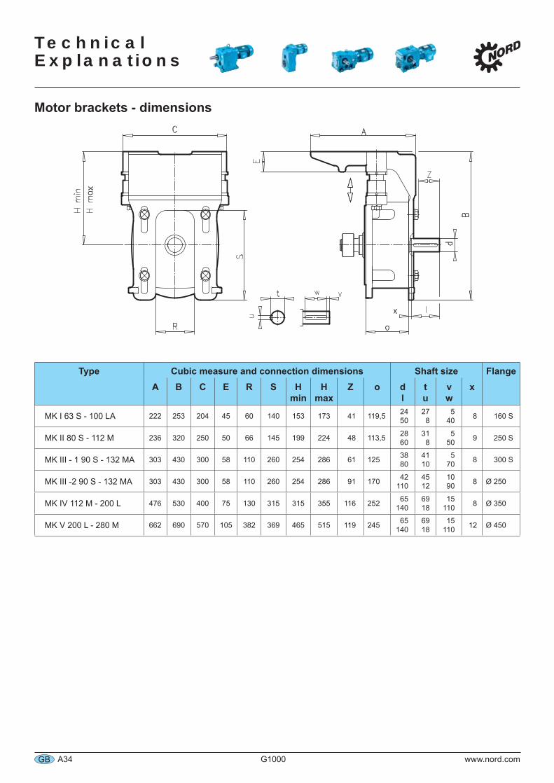
Motor brackets - dimensions
Type Cubic measure and connection dimensions Shaft size FlangeA B C E R S H
minH
maxZ o d
ltu
vw
x
MK I 63 S - 100 LA 222 253 204 45 60 140 153 173 41 119,5 2450
278
540 8 160 S
MK II 80 S - 112 M 236 320 250 50 66 145 199 224 48 113,5 2860
318
550 9 250 S
MK III - 1 90 S - 132 MA 303 430 300 58 110 260 254 286 61 125 3880
4110
570 8 300 S
MK III -2 90 S - 132 MA 303 430 300 58 110 260 254 286 91 170 42110
4512
1090 8 Ø 250
MK IV 112 M - 200 L 476 530 400 75 130 315 315 355 116 252 65140
6918
15110 8 Ø 350
MK V 200 L - 280 M 662 690 570 105 382 369 465 515 119 245 65140
6918
15110 12 Ø 450
Technical
Explanations
www.nord.com G1000 A35 GB
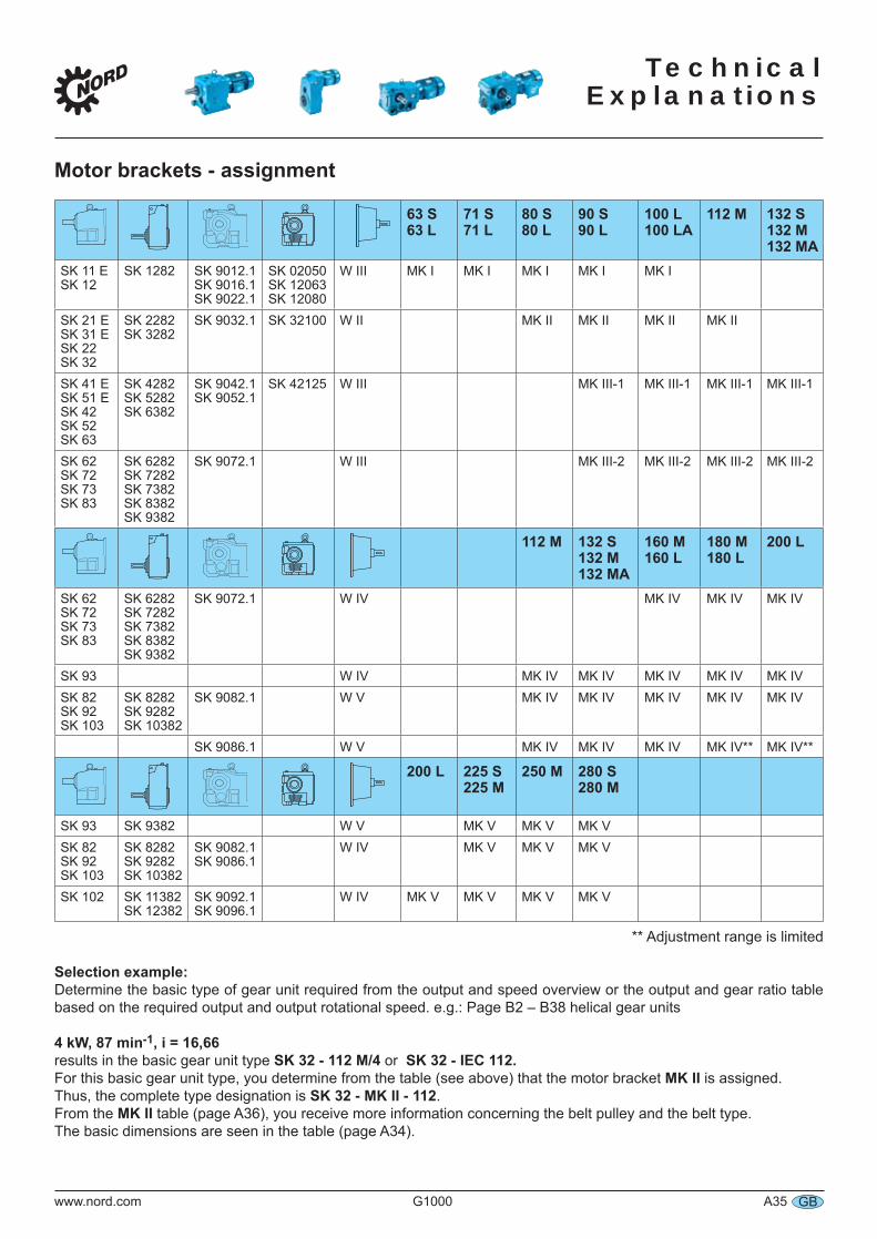
Motor brackets - assignment
63 S63 L
71 S71 L
80 S80 L
90 S90 L
100 L100 LA
112 M 132 S132 M132 MA
SK 11 ESK 12
SK 1282 SK 9012.1SK 9016.1SK 9022.1
SK 02050SK 12063SK 12080
W III MK I MK I MK I MK I MK I
SK 21 ESK 31 ESK 22SK 32
SK 2282SK 3282
SK 9032.1 SK 32100 W II MK II MK II MK II MK II
SK 41 ESK 51 ESK 42SK 52SK 63
SK 4282SK 5282SK 6382
SK 9042.1SK 9052.1
SK 42125 W III MK III-1 MK III-1 MK III-1 MK III-1
SK 62SK 72SK 73SK 83
SK 6282SK 7282SK 7382SK 8382SK 9382
SK 9072.1 W III MK III-2 MK III-2 MK III-2 MK III-2
112 M 132 S132 M132 MA
160 M160 L
180 M180 L
200 L
SK 62SK 72SK 73SK 83
SK 6282SK 7282SK 7382SK 8382SK 9382
SK 9072.1 W IV MK IV MK IV MK IV
SK 93 W IV MK IV MK IV MK IV MK IV MK IVSK 82SK 92SK 103
SK 8282SK 9282SK 10382
SK 9082.1 W V MK IV MK IV MK IV MK IV MK IV
SK 9086.1 W V MK IV MK IV MK IV MK IV** MK IV**
200 L 225 S225 M
250 M 280 S280 M
SK 93 SK 9382 W V MK V MK V MK VSK 82SK 92SK 103
SK 8282SK 9282SK 10382
SK 9082.1SK 9086.1
W IV MK V MK V MK V
SK 102 SK 11382SK 12382
SK 9092.1SK 9096.1
W IV MK V MK V MK V MK V
** Adjustment range is limited
Selection example:Determine the basic type of gear unit required from the output and speed overview or the output and gear ratio table based on the required output and output rotational speed. e.g.: Page B2 – B38 helical gear units 4 kW, 87 min-1, i = 16,66results in the basic gear unit type SK 32 - 112 M/4 or SK 32 - IEC 112.For this basic gear unit type, you determine from the table (see above) that the motor bracket MK II is assigned.Thus, the complete type designation is SK 32 - MK II - 112.From the MK II table (page A36), you receive more information concerning the belt pulley and the belt type.The basic dimensions are seen in the table (page A34).
Technical Explanations
A36 G1000 www.nord.comGB
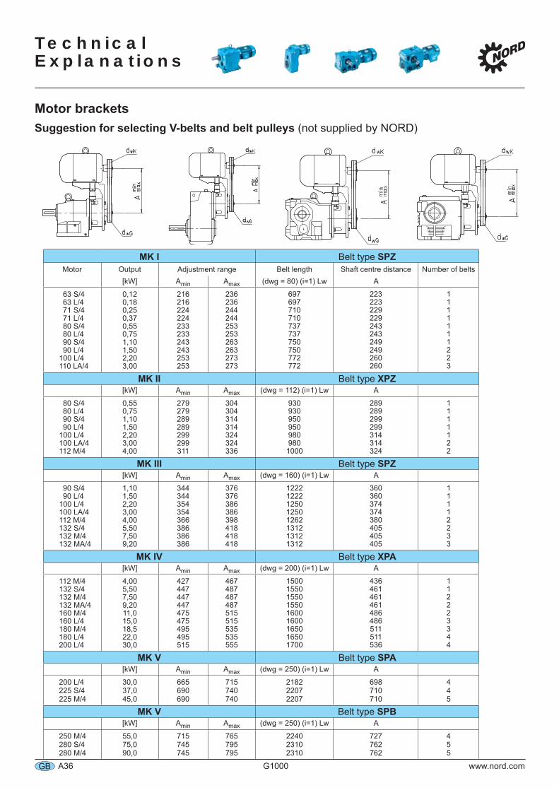
Motor bracketsSuggestion for selecting V-belts and belt pulleys (not supplied by NORD)
MK I Belt type SPZMotor Output Adjustment range Belt length Shaft centre distance Number of belts
[kW] Amin Amax (dwg = 80) (i=1) Lw A
63 S/463 L/471 S/471 L/480 S/480 L/490 S/490 L/4
100 L/4110 LA/4
0,120,180,250,370,550,751,101,502,203,00
216216224224233233243243253253
236236244244253253263263273273
697697710710737737750750772772
223223229229243243249249260260
1111111223
MK II Belt type XPZ[kW] Amin Amax (dwg = 112) (i=1) Lw A
80 S/480 L/490 S/490 L/4
100 L/4100 LA/4112 M/4
0,550,751,101,502,203,004,00
279279289289299299311
304304314314324324336
9309309509509809801000
289289299299314314324
1111122
MK III Belt type SPZ[kW] Amin Amax (dwg = 160) (i=1) Lw A
90 S/490 L/4
100 L/4100 LA/4112 M/4132 S/4132 M/4132 MA/4
1,101,502,203,004,005,507,509,20
344344354354366386386386
376376386386398418418418
12221222125012501262131213121312
360360374374380405405405
11112233
MK IV Belt type XPA[kW] Amin Amax (dwg = 200) (i=1) Lw A
112 M/4132 S/4132 M/4132 MA/4160 M/4160 L/4180 M/4180 L/4200 L/4
4,005,507,509,2011,015,018,522,030,0
427447447447475475495495515
467487487487515515535535555
150015501550155016001600165016501700
436461461461486486511511536
112223344
MK V Belt type SPA[kW] Amin Amax (dwg = 250) (i=1) Lw A
200 L/4225 S/4225 M/4
30,037,045,0
665690690
715740740
218222072207
698710710
445
MK V Belt type SPB[kW] Amin Amax (dwg = 250) (i=1) Lw A
250 M/4280 S/4280 M/4
55,075,090,0
715745745
765795795
224023102310
727762762
455
Technical
Explanations
www.nord.com G1000 A37 GB
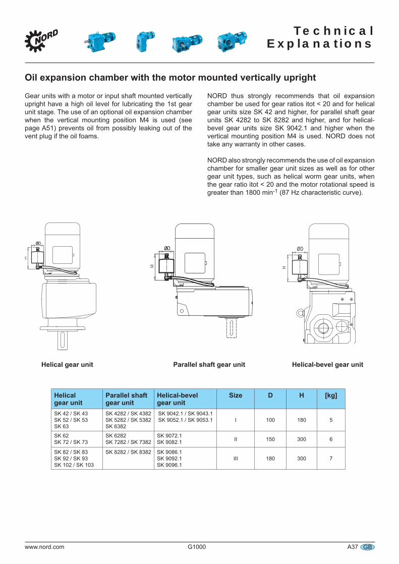
Oil expansion chamber with the motor mounted vertically upright
Helical gear unit
Parallel shaftgear unit
Helical-bevelgear unit
Size D H [kg]
SK 42 / SK 43SK 52 / SK 53SK 63
SK 4282 / SK 4382SK 5282 / SK 5382SK 6382
SK 9042.1 / SK 9043.1SK 9052.1 / SK 9053.1 I 100 180 5
SK 62SK 72 / SK 73
SK 6282SK 7282 / SK 7382
SK 9072.1SK 9082.1 II 150 300 6
SK 82 / SK 83SK 92 / SK 93SK 102 / SK 103
SK 8282 / SK 8382 SK 9086.1SK 9092.1SK 9096.1
III 180 300 7
Gear units with a motor or input shaft mounted vertically upright have a high oil level for lubricating the 1st gear unit stage. The use of an optional oil expansion chamber when the vertical mounting position M4 is used (see page A51) prevents oil from possibly leaking out of the vent plug if the oil foams.
NORD thus strongly recommends that oil expansion chamber be used for gear ratios itot < 20 and for helical gear units size SK 42 and higher, for parallel shaft gear units SK 4282 to SK 8282 and higher, and for helical-bevel gear units size SK 9042.1 and higher when the vertical mounting position M4 is used. NORD does not take any warranty in other cases.
NORD also strongly recommends the use of oil expansion chamber for smaller gear unit sizes as well as for other gear unit types, such as helical worm gear units, when the gear ratio itot < 20 and the motor rotational speed is greater than 1800 min-1 (87 Hz characteristic curve).
Helical-bevel gear unitHelical gear unit Parallel shaft gear unit
Technical Explanations
A38 G1000 www.nord.comGB
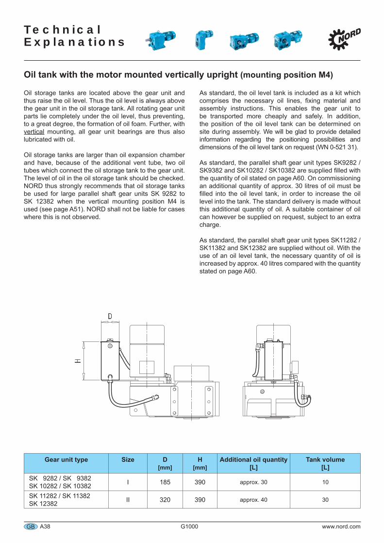
Oil tank with the motor mounted vertically upright (mounting position M4)
Gear unit type Size D[mm]
H[mm]
Additional oil quantity[L]
Tank volume [L]
SK 9282 / SK 9382SK 10282 / SK 10382 I 185 390 approx. 30 10
SK 11282 / SK 11382SK 12382 II 320 390 approx. 40 30
Oil storage tanks are located above the gear unit and thus raise the oil level. Thus the oil level is always above the gear unit in the oil storage tank. All rotating gear unit parts lie completely under the oil level, thus preventing, to a great degree, the formation of oil foam. Further, with vertical mounting, all gear unit bearings are thus also lubricated with oil.
Oil storage tanks are larger than oil expansion chamber and have, because of the additional vent tube, two oil tubes which connect the oil storage tank to the gear unit. The level of oil in the oil storage tank should be checked. NORD thus strongly recommends that oil storage tanks be used for large parallel shaft gear units SK 9282 to SK 12382 when the vertical mounting position M4 is used (see page A51). NORD shall not be liable for cases where this is not observed.
As standard, the oil level tank is included as a kit which comprises the necessary oil lines, fixing material and assembly instructions. This enables the gear unit to be transported more cheaply and safely. In addition, the position of the oil level tank can be determined on site during assembly. We will be glad to provide detailed information regarding the positioning possibilities and dimensions of the oil level tank on request (WN 0-521 31).
As standard, the parallel shaft gear unit types SK9282 / SK9382 and SK10282 / SK10382 are supplied filled with the quantity of oil stated on page A60. On commissioning an additional quantity of approx. 30 litres of oil must be filled into the oil level tank, in order to increase the oil level into the tank. The standard delivery is made without this additional quantity of oil. A suitable container of oil can however be supplied on request, subject to an extra charge.
As standard, the parallel shaft gear unit types SK11282 / SK11382 and SK12382 are supplied without oil. With the use of an oil level tank, the necessary quantity of oil is increased by approx. 40 litres compared with the quantity stated on page A60.
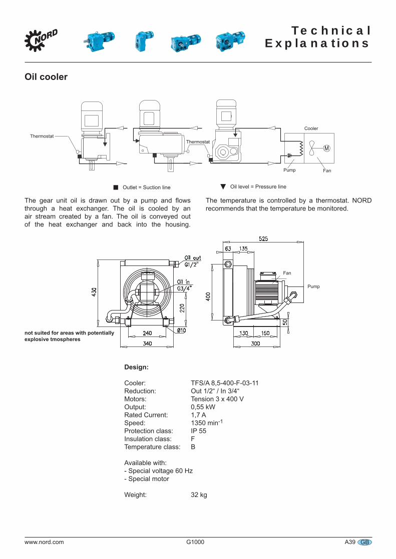
Technical
Explanations
www.nord.com G1000 A39 GB
Oil cooler
The gear unit oil is drawn out by a pump and flows through a heat exchanger. The oil is cooled by an air stream created by a fan. The oil is conveyed out of the heat exchanger and back into the housing.
The temperature is controlled by a thermostat. NORD recommends that the temperature be monitored.
not suited for areas with potentially explosive tmospheres
ThermostatThermostat
Cooler
FanPump
▼Outlet = Suction line Oil level = Pressure line
Fan
Pump
Design:
Cooler: TFS/A 8,5-400-F-03-11Reduction: Out 1/2“ / In 3/4“Motors: Tension 3 x 400 VOutput: 0,55 kWRated Current: 1,7 ASpeed: 1350 min-1
Protection class: IP 55Insulation class: FTemperature class: B
Available with:- Special voltage 60 Hz- Special motor
Weight: 32 kg
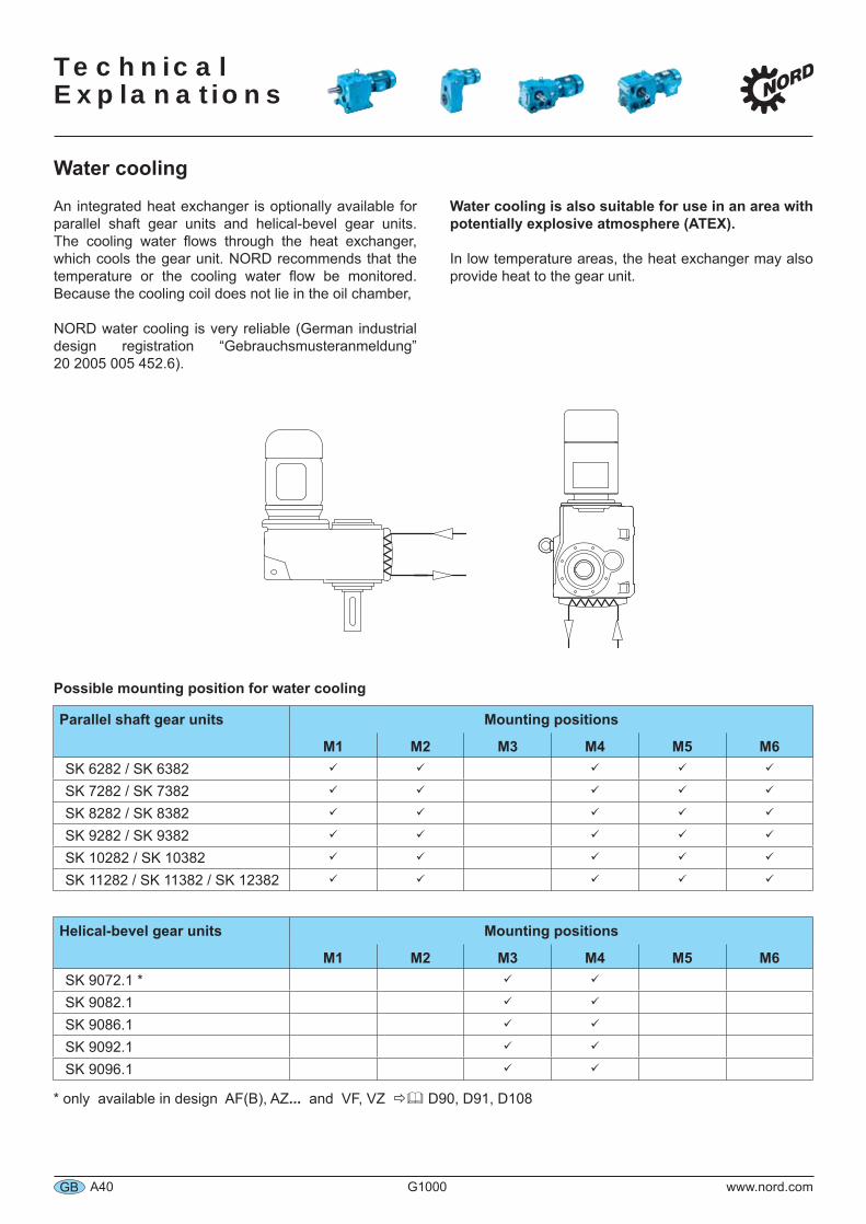
Technical Explanations
A40 G1000 www.nord.comGB
Water cooling
An integrated heat exchanger is optionally available for parallel shaft gear units and helical-bevel gear units. The cooling water flows through the heat exchanger, which cools the gear unit. NORD recommends that the temperature or the cooling water flow be monitored. Because the cooling coil does not lie in the oil chamber,
NORD water cooling is very reliable (German industrial design registration “Gebrauchsmusteranmeldung” 20 2005 005 452.6).
Water cooling is also suitable for use in an area with potentially explosive atmosphere (ATEX).
In low temperature areas, the heat exchanger may also provide heat to the gear unit.
Possible mounting position for water cooling
Parallel shaft gear units Mounting positions
M1 M2 M3 M4 M5 M6SK 6282 / SK 6382SK 7282 / SK 7382SK 8282 / SK 8382SK 9282 / SK 9382SK 10282 / SK 10382SK 11282 / SK 11382 / SK 12382
Helical-bevel gear units Mounting positions
M1 M2 M3 M4 M5 M6SK 9072.1 *SK 9082.1SK 9086.1SK 9092.1SK 9096.1
* only available in design AF(B), AZ... and VF, VZ D90, D91, D108
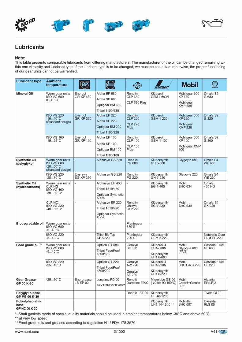
www.nord.com G1000 A41 GB
Lubricants
Note:This table presents comparable lubricants from differing manufacturers. The manufacturer of the oil can be changed remaining wi-thin one viscosity and lubricant type. If the lubricant type is to be changed, we must be consulted; otherwise, the proper functioning of our gear units cannot be warrantied.
Lubricant type Ambient temperature
Mineral Oil Worm gear unitsISO VG 6800...40°C
Energol GR-XP 680
Alpha EP 680
Alpha SP 680
Optigear BM 680
Tribol 1100/680
RenolinCLP 680
CLP 680 Plus
KlüberoilGEM 1-680N
Mobilgear 600XP 680
MobilgearXMP 680
Omala S2 G 680
ISO VG 220-10...40°C(Standard design)
EnergolGR-XP 220
Alpha EP 220
Alpha SP 220
Optigear BM 220
Tribol 1100/220
RenolinCLP 220
CLP 220Plus
KlüberoilGEM 1-220
Mobilgear 600XP 220
MobilgearXMP 220
Omala S2 G 220
ISO VG 100-15...25°C
EnergolGR-XP 100
Alpha EP 100
Alpha SP 100
Optigear BM 100
Tribol 1100/100
RenolinCLP 100
CLP 100Plus
KlüberoilGEM 1-100
Mobilgear 600XP 100
Mobilgear XMP 100
Omala S2 G 100
Synthetic Oil(polyglykol)
Worm gear unitsISO VG 680-20...60°C(Standard design)
- Alphasyn GS 680 RenolinPG 680
KlübersynthGH 6-680
Glygoyle 680 Omala S4 WE 680
ISO VG 220-25...80°C
EnersynSG-XP 220
Alphasyn GS 220 RenolinPG 220
KlübersynthGH 6-220
Glygoyle 220 Omala S4 WE 220
Synthetic Oil (hydrocarbons)
Worm gear unitsCLP HGISO VG 460-30...80°C*
- Alphasyn EP 460
Tribol 1510/460
Optigear Synthetic X 460
- KlübersynthEG 4-460
MobilSHC 634
Omala 460 HD
CLP HC ISO VG 220-40...80°C*
- Alphasyn EP 220
Tribol 1510/220
Optigear Synthetic X 220
RenolinUnisynCLP 220
KlübersynthEG 4-220
MobilSHC 630
Omala S4 GX 220
Biodegradable oil Worm gear unitsISO VG 680-5...40°C
- - Plantogear680 S
- - -
ISO VG 220-5...40°C
- Tribol Bio Top1418/220
Plantogear220 S
KlübersynthGEM 2-220
- Naturelle Gear Fluid EP 220
Food grade oil 1) Worm gear unitsISO VG 680-5...40°C
- Optileb GT 680
Tribol FoodPoof 1800/680
GeralynSF 680
Klüberoil 4UH1-680N
KlübersynthUH1 6-680
Mobil Glygoyle 680(PAG)
Cassida FluidGL 680
ISO VG 220-25...40°C
- Optileb GT 220
Tribol FoodPoof 1800/220
GeralynAW 220
GeralynSF 220
Klüberoil 4UH1-220N
KlübersynthUH1 6-220
Mobil SHC Cibus 220
Cassida FluidGL 220
Gear-GreaseGP 00 K-30
-25...60°C EnergreaseLS-EP 00
Longtime PD 00
Tribol 3020/1000-00**
RenolitDuraplex EP00
Microlube GB 00(-20 bis 90/150°C)
Mobil Chassis Grease LBZ
Alvania EP(LF)2
PolyglykolbaseGP PG 00 K-30
Renolit LST 00 KlübersynthGE 46-1200
Tivela GL00
Polyalphaolefi n-base GP HC 00 K-30
KlübersynthUH1 14-1600 1)
MobilithSHC 007
Cassida RLS 00
* Shaft gaskets made of special quality materials should be used in ambient temperatures below -30°C and above 60°C.** at very low speed1) Food grade oils and greases according to regulation H1 / FDA 178.3570
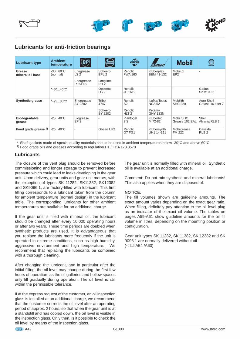
A42 G1000 www.nord.comGB
Lubricants for anti-friction bearings
Lubricants
The closure of the vent plug should be removed before commissioning and longer storage to prevent increased pressure which could lead to leaks developing in the gear unit. Upon delivery, gear units and gear unit motors, with the exception of types SK 11282, SK11382, SK12382 and SK9096.1, are factory- lled with lubricant. This rst lling corresponds to a lubricant taken from the column for ambient temperature (normal design) in the lubricant table. The corresponding lubricants for other ambient temperatures are available for an additional charge.
If the gear unit is lled with mineral oil, the lubricant should be changed after every 10,000 operating hours or after two years. These time periods are doubled when synthetic products are used. It is advantageous that you replace the lubricants more frequently if the unit is operated in extreme conditions, such as high humidity, aggressive environment and high temperature. We recommend that replacing the lubricants be combined with a thorough cleaning.
After changing the lubricant, and in particular after the initial lling, the oil level may change during the rst few hours of operation, as the oil galleries and hollow spaces only ll gradually during operation. The oil level is still within the permissible tolerance.
If at the express request of the customer, an oil inspection glass is installed at an additional charge, we recommend that the customer corrects the oil level after an operating period of approx. 2 hours, so that when the gear unit is at a standstill and has cooled down, the oil level is visible in the inspection glass. Only then, is it possible to check the oil level by means of the inspection glass.
The gear unit is normally lled with mineral oil. Synthetic oil is available at an additional charge.
Comment: Do not mix synthetic and mineral lubricants! This also applies when they are disposed of.
NOTICE:The ll volumes shown are guideline amounts. The exact amount varies depending on the exact gear ratio. When lling, de nitely pay attention to the oil level plug as an indicator of the exact oil volume. The tables on pages A59-A61 show guideline amounts for the oil ll volume in litres, depending on the mounting position or con guration.
Gear unit types SK 11282, SK 11382, SK 12382 and SK 9096.1 are normally delivered without oil. ( A54 /A60)
Lubricant type Ambient temperature
Greasemineral oil base
-30...60°C(normal)
EnegreaseLS 2
Energrease LS2-EP2
SpheerolEPL 2
Longtime PD 2
RenolitFWA 160
KlüberplexBEM 41-132
Mobilux EP2
-
*-50...40°C - Optitemp LG 2
RenolitJP 1619
- - Gadus S2 V100 2
Synthetic grease *-25...80°C Energrease SY 2202
Tribol 4747
Spheerol SY 2202
Renolit S2
RenolitHLT 2
Iso ex TopasNCA 52
PetamoGHY 133N
MobilithSHC 220
Aero ShellGrease 16 oder 7
Biodegradable grease
-25...40°C Biogrease EP 2
- Plantogel2 S
KlüberbioM 72-82
Mobil SHCGrease 102 EAL
ShellAlvania RLB 2
Food grade grease 1) -25...40°C - Obeen UF2 RenolitG7 FG1
KlübersynthUH1 14-151
MobilgreaseFM 222
CassidaRLS 2
* Shaft gaskets made of special quality materials should be used in ambient temperatures below -30°C and above 60°C.1) Food grade oils and greases according to regulation H1 / FDA 178.3570
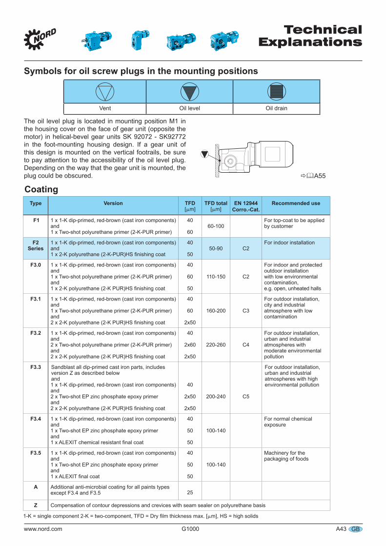
TechnicalExplanations
www.nord.com G1000 A43 GB
Symbols for oil screw plugs in the mounting positions
Coating
Vent Oil level Oil drain
The oil level plug is located in mounting position M1 in the housing cover on the face of gear unit (opposite the motor) in helical-bevel gear units SK 92072 - SK92772 in the foot-mounting housing design. If a gear unit of this design is mounted on the vertical footrails, be sure to pay attention to the accessibility of the oil level plug. Depending on the way that the gear unit is mounted, the plug could be obscured. A55
Type Version TFD[m]
TFD total[m]
EN 12944 Corro.-Cat.
Recommended use
F1 1 x 1-K dip-primed, red-brown (cast iron components)and 1 x Two-shot polyurethane primer (2-K-PUR primer)
40
6060-100
For top-coat to be applied by customer
F2Series
1 x 1-K dip-primed, red-brown (cast iron components)and
40
5050-90 C2
For indoor installation
F3.0 1 x 1-K dip-primed, red-brown (cast iron components)and 1 x Two-shot polyurethane primer (2-K-PUR primer)and
40
60
50
110-150 C2
For indoor and protected outdoor installation with low environmental contamination, e.g. open, unheated halls
F3.1 1 x 1-K dip-primed, red-brown (cast iron components)and1 x Two-shot polyurethane primer (2-K-PUR primer)and
40
60
2x50
160-200 C3
For outdoor installation, city and industrial atmosphere with low contamination
F3.2 1 x 1-K dip-primed, red-brown (cast iron components)and2 x Two-shot polyurethane primer (2-K-PUR primer)and
40
2x60
2x50
220-260 C4
For outdoor installation, urban and industrial atmospheres with moderate environmental pollution
F3.3
1 x 1-K dip-primed, red-brown (cast iron components)and2 x Two-shot EP zinc phosphate epoxy primerand
40
2x50
2x50
200-240 C5
F3.4 1 x 1-K dip-primed, red-brown (cast iron components)and1 x Two-shot EP zinc phosphate epoxy primerand
40
50
50
100-140
For normal chemical exposure
F3.5 1 x 1-K dip-primed, red-brown (cast iron components)and1 x Two-shot EP zinc phosphate epoxy primerand
40
50
50
100-140
Machinery for the packaging of foods
A Additional anti-microbial coating for all paints types except F3.4 and F3.5 25
Z Compensation of contour depressions and crevices with seam sealer on polyurethane basis
m], HS = high solids
Sandblast all dip-primed cast iron parts, includesversion Z as described below and
For outdoor installation, urban and industrial atmospheres with high environmental pollution
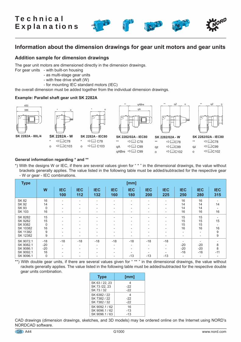
Technical Explanations
A44 G1000 www.nord.comGB
Information about the dimension drawings for gear unit motors and gear units
Addition sample for dimension drawingsThe gear unit motors are dimensioned directly in the dimension drawings.For gear units - with built-on housing - as multi-stage gear units - with free drive shaft (W) - for mounting IEC standard motors (IEC)the overall dimension must be added together from the individual dimension drawings.
Example: Parallel shaft gear unit SK 2282A
General information regarding * and ***) With the designs W or IEC, if there are several values given for “ * ” in the dimensional drawings, the value without brackets generally applies. The value listed in the following table must be added/subtracted for the respective gear - W or gear - IEC combinations.
Type [mm]W IEC
100IEC112
IEC 132
IEC 160
IEC 180
IEC 200
IEC 225
IEC 250
IEC 280
IEC 315
SK 82SK 92SK 93SK 103
16140
16
----
----
----
----
----
----
----
16141416
16141416
-14-
16
SK 8282SK 9282SK 9382SK 10382SK 11382SK 12382
15150
1699
------
------
------
------
------
------
------
15151516--
15151516--
-15-
1699
SK 9072.1SK 9082.1SK 9086.1SK 9092.1SK 9096.1
-18-20-20160
-18----
-18----
-18----
-18----
-18---
-13
-18---
-13
-18---
-13
--20-20-16-
--20-20-16-
-88
-11-
**) With double gear units, if there are several values given for “ ** ” in the dimensional drawings, the value without rackets generally applies. The value listed in the following table must be added/subtracted for the respective double gear units combination.
Type [mm]SK 63 / 22, 23SK 73 /22, 23SK 73 / 32
4-22-22
SK 6382 / 22SK 7382 / 22SK 7382 / 32
4-22-22
SK 9092.1 / 62 SK 9096.1 / 62SK 9096.1 / 63
16-13-13
CAD drawings (dimension drawings, sketches, and 3D models) may be ordered online on the Internet using NORD’s NORDCAD software.
SK 2282A - W* C78o C103
SK 2282A - 80L/4 SK 2282A - IEC80* C78o C103
SK 2282/02A - IEC80** C78qA C99qABre C99
SK 2282/02A - W** C78qz C99o C102
SK 2282/02A - IEC80** C78qz C99o C102
450
386 * o * o
** qABre ** qZ o ** qZ o
qA
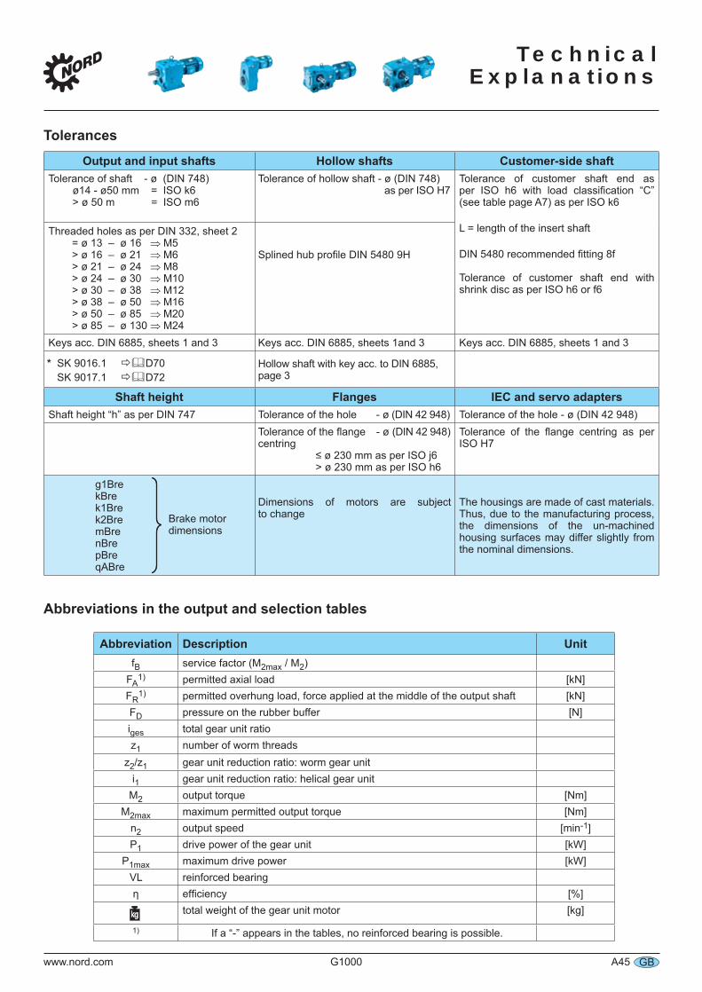
Technical
Explanations
www.nord.com G1000 A45 GB
Tolerances
Output and input shafts Hollow shafts Customer-side shaftTolerance of shaft - ø (DIN 748)
ø14 - ø50 mm = ISO k6> ø 50 m = ISO m6
Tolerance of hollow shaft - ø (DIN 748) as per ISO H7
Tolerance of customer shaft end as per ISO h6 with load classification “C” (see table page A7) as per ISO k6
L = length of the insert shaft
DIN 5480 recommended fitting 8f
Tolerance of customer shaft end with shrink disc as per ISO h6 or f6
Threaded holes as per DIN 332, sheet 2= ø 13 – ø 16 ⇒ M5 > ø 16 – ø 21 ⇒ M6 > ø 21 – ø 24 ⇒ M8> ø 24 – ø 30 ⇒ M10> ø 30 – ø 38 ⇒ M12> ø 38 – ø 50 ⇒ M16> ø 50 – ø 85 ⇒ M20> ø 85 – ø 130 ⇒ M24
Splined hub profile DIN 5480 9H
Keys acc. DIN 6885, sheets 1 and 3 Keys acc. DIN 6885, sheets 1and 3 Keys acc. DIN 6885, sheets 1 and 3
* SK 9016.1 D70 SK 9017.1 D72
Hollow shaft with key acc. to DIN 6885, page 3
Shaft height Flanges IEC and servo adaptersShaft height “h” as per DIN 747 Tolerance of the hole - ø (DIN 42 948) Tolerance of the hole - ø (DIN 42 948)
Tolerance of the flange - ø (DIN 42 948) centring
≤ ø 230 mm as per ISO j6> ø 230 mm as per ISO h6
Tolerance of the flange centring as per ISO H7
g1BrekBrek1Brek2BremBrenBre pBre qABre
Dimensions of motors are subject to change
The housings are made of cast materials. Thus, due to the manufacturing process, the dimensions of the un-machined housing surfaces may differ slightly from the nominal dimensions.
Abbreviations in the output and selection tables
Abbreviation Description UnitfB service factor (M2max / M2)
FA1) permitted axial load [kN]
FR1) permitted overhung load, force applied at the middle of the output shaft [kN]
FD pressure on the rubber buffer [N]iges total gear unit ratioz1 number of worm threads
z2/z1 gear unit reduction ratio: worm gear uniti1 gear unit reduction ratio: helical gear unit
M2 output torque [Nm]M2max maximum permitted output torque [Nm]
n2 output speed [min-1]P1 drive power of the gear unit [kW]
P1max maximum drive power [kW]VL reinforced bearingη efficiency [%]
total weight of the gear unit motor [kg]
1) If a “-” appears in the tables, no reinforced bearing is possible.
Brake motor dimensions
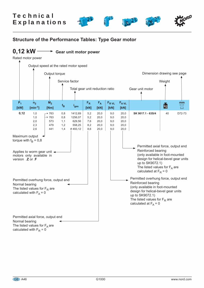
Technical Explanations
A46 G1000 www.nord.comGB
Applies to worm gear unit motors only available in version .Z or .F
P1 n2 M2 fB igesFR FA FR VL FA VL mm
[kW] [min-1] [Nm] [kN] [kN] [kN] [kN]
0,12 1,0 763 0,8 1412,69 5,2 20,0 9,0 20,0 SK 9017.1 - 63S/4 40 D72-731,0 763 0,8 1256,07 5,2 20,0 9,0 20,02,0 573 1,1 629,56 7,6 20,0 9,0 20,02,3 479 1,2 558,25 8,2 20,0 9,0 20,02,6 441 1,4 # 493,12 8,6 20,0 9,0 20,0
Maximum output torque with fB = 0,8
Structure of the Performance Tables: Type Gear motor
0,12 kW Gear unit motor power
Total gear unit reduction ratio
Service factor
Output torque
Output speed at the rated motor speed
Rated motor power
Gear unit motor
Weight
Dimension drawing see page
Permitted overhung force, output endNormal bearingThe listed values for FR arecalculated with FA = 0
Permitted axial force, output endNormal bearingThe listed values for FA arecalculated with FR = 0
Permitted axial force, output endReinforced bearing(only available in foot-mounteddesign for helical-bevel gear units up to SK9072.1)The listed values for FA are calculated at FR = 0
Permitted overhung force, output endReinforced bearing(only available in foot-mounteddesign for helical-bevel gear unitsup to SK9072.1)The listed values for FR are calculated at FA = 0
**
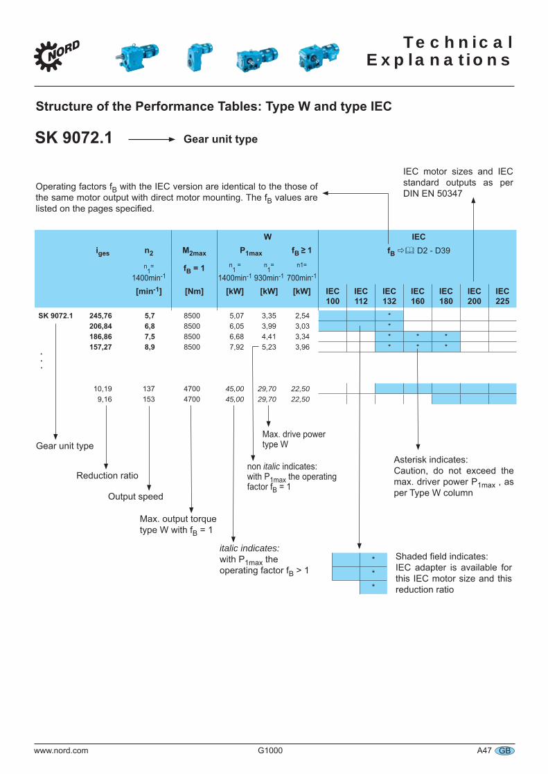
Technical
Explanations
www.nord.com G1000 A47 GB
W IECiges n2 M2max P1max fB ≥ 1 fB D2 - D39
n1= fB = 1 n
1 = n
1= n1=
1400min-1 1400min-1 930min-1 700min-1
[min-1] [Nm] [kW] [kW] [kW] IEC100
IEC112
IEC 132
IEC160
IEC180
IEC200
IEC225
SK 9072.1 245,76 5,7 8500 5,07 3,35 2,54 *206,84 6,8 8500 6,05 3,99 3,03 *186,86 7,5 8500 6,68 4,41 3,34 * * *157,27 8,9 8500 7,92 5,23 3,96 * * *
10,19 137 4700 45,00 29,70 22,509,16 153 4700 45,00 29,70 22,50
SK 9072.1 Gear unit type
Gear unit type
Reduction ratio
Output speed
Max. output torquetype W with fB = 1
italic indicates: with P1max the operating factor fB > 1
***
Shaded field indicates:IEC adapter is available for this IEC motor size and this reduction ratio
Max. drive power type W
non italic indicates: with P1max the operating
factor fB = 1
Operating factors fB with the IEC version are identical to the those of the same motor output with direct motor mounting. The fB values are listed on the pages specified.
..
.
IEC motor sizes and IEC standard outputs as per DIN EN 50347
Asterisk indicates:Caution, do not exceed the max. driver power P1max , as per Type W column
Structure of the Performance Tables: Type W and type IEC
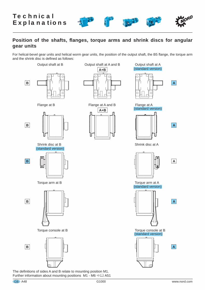
TechnicalExplanations
A48 G1000 www.nord.comGB
Position of the shafts, anges, torque arms and shrink discs for angular gear unitsFor helical-bevel gear units and helical worm gear units, the position of the output shaft, the B5 ange, the torque arm and the shrink disc is de ned as follows:
B A
Torque arm at ATorque arm at B
B A
Shrink disc at B Shrink disc at A
The de nitions of sides A and B relate to mounting position M1.Further information about mounting positions M1 - M6 A51
B A
Output shaft at B Output shaft at A and B Output shaft at AA+B
Torque console at B Torque console at B
AB
B A
Flange at B Flange at A and B Flange at AA+B
(standard version)
(standard version)
(standard version)
(standard version)
(standard version)
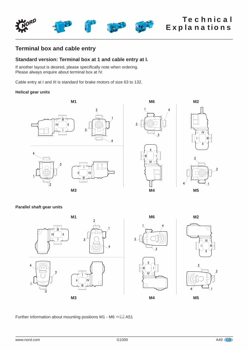
TechnicalExplanations
www.nord.com G1000 A49 GB
Terminal box and cable entry
Standard version: Terminal box at 1 and cable entry at I.If another layout is desired, please speci cally note when ordering.Please always enquire about terminal box at IV.
Cable entry at I and III is standard for brake motors of size 63 to 132.
Helical gear units
Parallel shaft gear units
Further information about mounting positions M1 - M6 A51
11
22
33
44
II
IIII
IIIIII
IVIV
IVIV
IIIIII
44
33
22
IIII
II
11
IVIV
IIIIII
44
33
22
IIII
II
11
IVIV
IIIIII
44
33
22
IIII
II
11
M1
M3
M2M6
2
1
2
3
4
I
II IV
III
1
3
4
I
II
III
IV
IV
III3
I
II
41
2
III
II
IV
I
4
3
2
1
M3
M2M6M1
M5M4
M5M4
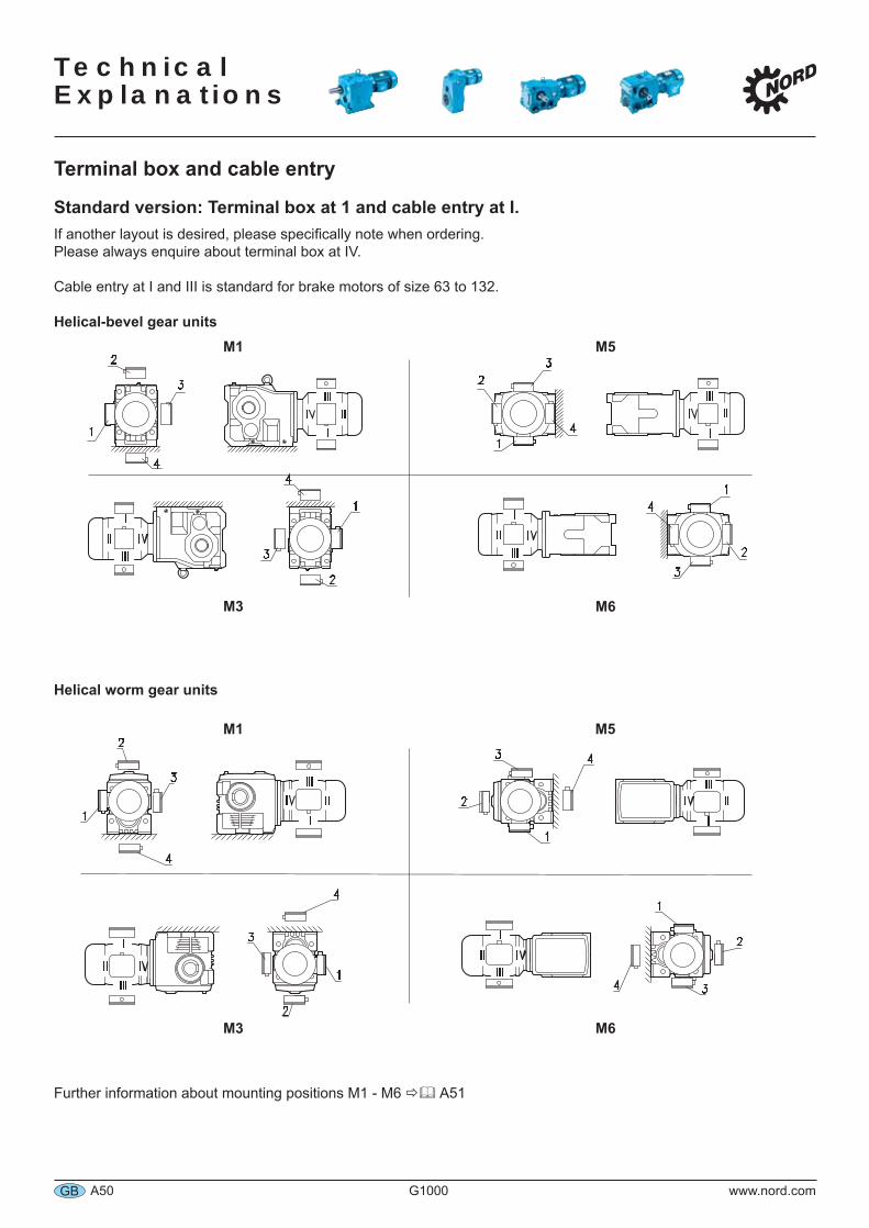
Technical Explanations
A50 G1000 www.nord.comGB
Terminal box and cable entry
Standard version: Terminal box at 1 and cable entry at I.If another layout is desired, please specifically note when ordering.Please always enquire about terminal box at IV.
Cable entry at I and III is standard for brake motors of size 63 to 132.
Helical-bevel gear units
Helical worm gear units
Further information about mounting positions M1 - M6 A51
M1
M3 M6
M5
M3 M6
M5M1
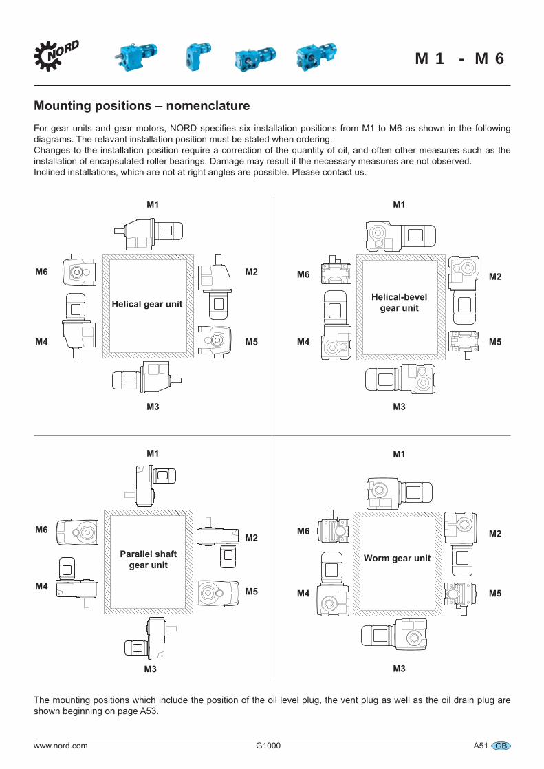
www.nord.com G1000 A51 GB
Mounting positions – nomenclatureFor gear units and gear motors, NORD specifies six installation positions from M1 to M6 as shown in the following diagrams. The relavant installation position must be stated when ordering.Changes to the installation position require a correction of the quantity of oil, and often other measures such as the installation of encapsulated roller bearings. Damage may result if the necessary measures are not observed.Inclined installations, which are not at right angles are possible. Please contact us.
Helical gear unitHelical-bevel
gear unit
Parallel shaftgear unit
Worm gear unit
M1
M4
M6
M1
M6
M4
M3
M5
M2
M3
M5
M2
M1
M5
M2
M4
M6
M1
M3
M5
M2
M4
M6
M3
The mounting positions which include the position of the oil level plug, the vent plug as well as the oil drain plug are shown beginning on page A53.
M1 - M6
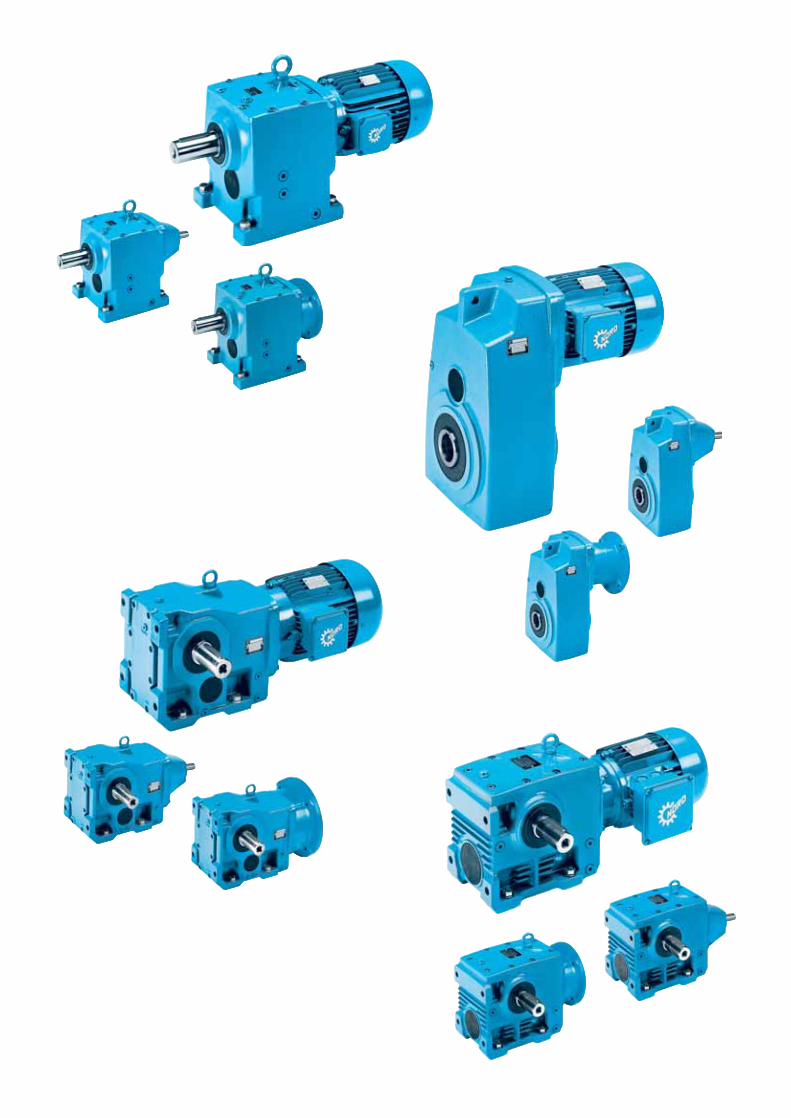
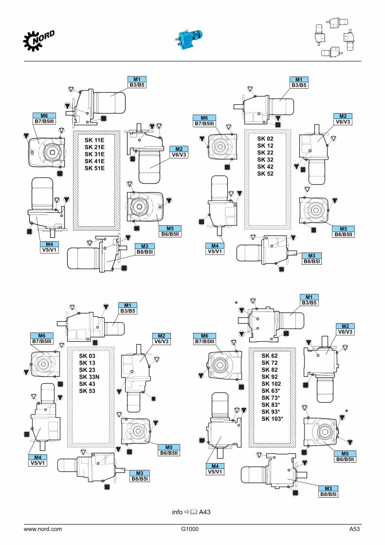
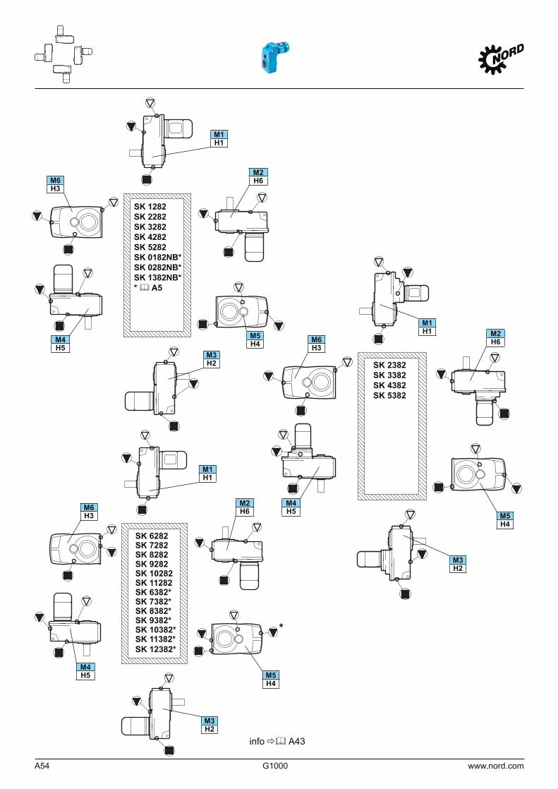
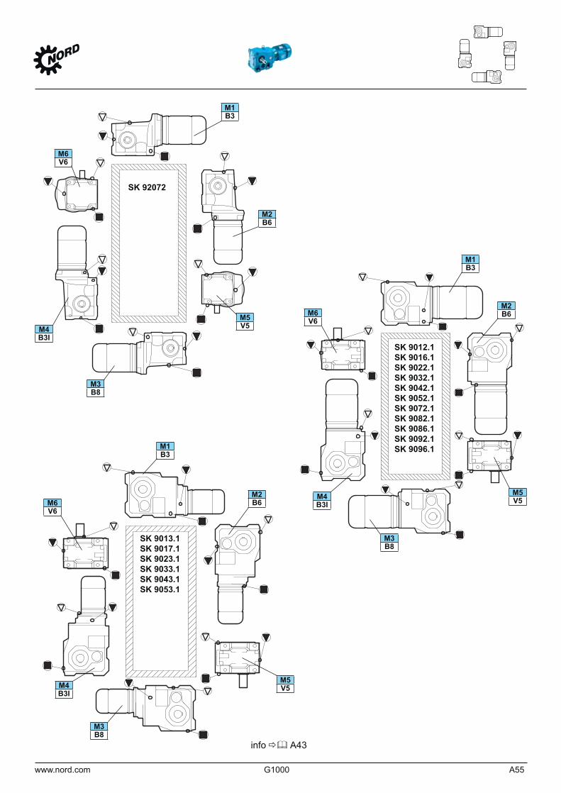
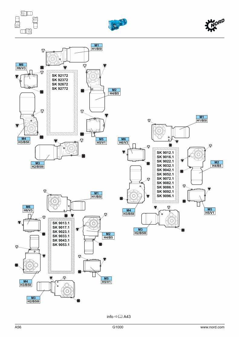
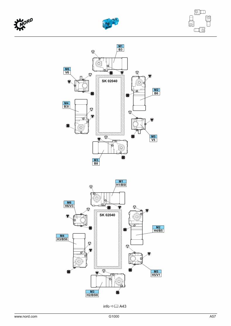
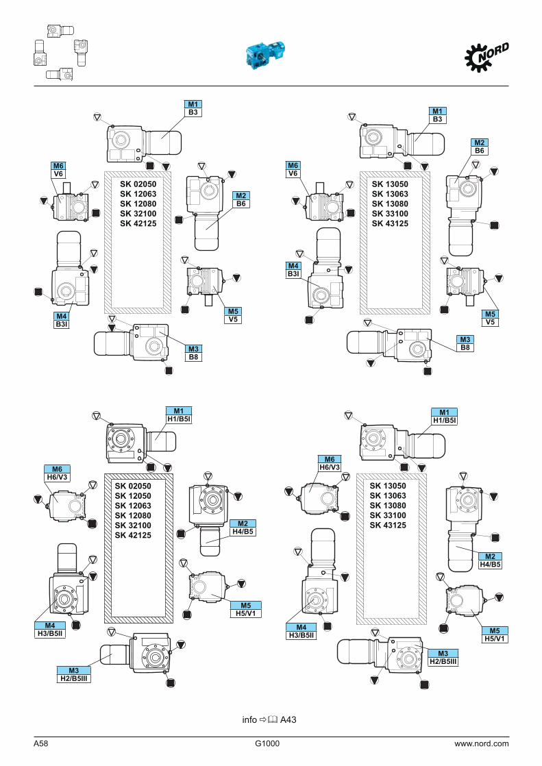
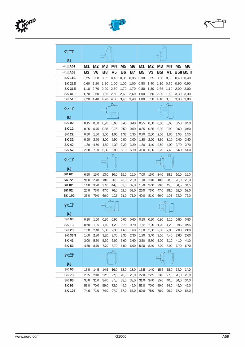
www.nord.com G1000 A59
[L]
A51 M1 M2 M3 M4 M5 M6 M1 M2 M3 M4 M5 M6A53 B3 V6 B8 V5 B6 B7 B5 V3 B5I V1 B5II B5III
SK 11E 0,25 0,50 0,55 0,40 0,35 0,35 0,30 0,35 0,50 0,30 0,40 0,40SK 21E 0,60 1,20 1,20 1,00 1,00 1,00 0,50 1,40 1,10 0,70 0,90 0,90SK 31E 1,10 2,70 2,20 2,30 1,70 1,70 0,80 1,30 1,65 1,10 2,00 2,00SK 41E 1,70 2,60 3,30 2,50 2,60 2,60 1,00 2,60 2,80 1,60 3,30 3,30SK 51E 2,20 4,40 4,70 4,00 3,40 3,40 1,80 3,50 4,10 3,00 3,80 3,80
[L]SK 02 0,15 0,60 0,70 0,60 0,40 0,40 0,25 0,60 0,60 0,60 0,50 0,50SK 12 0,25 0,75 0,85 0,75 0,50 0,50 0,35 0,85 0,90 0,90 0,60 0,60SK 22 0,50 1,80 2,00 1,80 1,35 1,35 0,70 2,00 2,00 1,80 1,55 1,55SK 32 0,90 2,50 3,00 2,90 2,00 2,00 1,30 2,90 3,30 3,10 2,40 2,40SK 42 1,30 4,50 4,50 4,30 3,20 3,20 1,80 4,40 4,50 4,00 3,70 3,70SK 52 2,50 7,00 6,80 6,80 5,10 5,10 3,00 6,80 6,20 7,40 5,60 5,60
[L]SK 62 6,50 15,0 13,0 16,0 15,0 15,0 7,00 15,0 14,0 18,5 16,0 16,0SK 72 9,00 23,0 18,0 26,0 23,0 23,0 10,0 23,0 18,5 28,0 23,0 23,0SK 82 14,0 35,0 27,0 44,0 32,0 32,0 15,0 37,0 29,0 45,0 34,5 34,5SK 92 25,0 73,0 47,0 76,0 52,0 52,0 26,0 73,0 47,0 78,0 52,0 52,0SK 102 36,0 79,0 66,0 102 71,0 71,0 40,0 81,0 66,0 104 72,0 72,0
[L]SK 03 0,30 1,00 0,80 0,90 0,60 0,60 0,50 0,80 0,90 1,10 0,80 0,80SK 13 0,60 1,25 1,10 1,20 0,70 0,70 0.,85 1,20 1,20 1,20 0,95 0,95SK 23 1,30 2,40 2,30 2,35 1,60 1,60 1,50 2,60 2,50 2,80 2,80 2,80SK 33N 1,60 2,90 3,20 3,70 2,30 2,30 1,90 3,40 3,50 4,40 2,60 2,60SK 43 3,00 5,60 5,30 6,60 3,60 3,60 3,50 5,70 5,00 6,10 4,10 4,10SK 53 4,50 8,70 7,70 8,70 6,00 6,00 5,20 8,40 7,00 8,90 6,70 6,70
[L]SK 63 13,0 14,5 14,5 16,0 13,0 13,0 13,5 14,0 15,5 18,0 14,0 14,0SK 73 20,5 20,0 22,5 27,0 20,0 20,0 22,0 22,5 23,0 27,5 20,0 20,0SK 83 30,0 31,0 34,0 37,0 33,0 33,0 31,0 34,0 35,0 40,0 34,0 34,0SK 93 53,0 70,0 59,0 72,0 49,0 49,0 53,0 70,0 59,0 74,0 49,0 49,0SK 103 74,0 71,0 74,0 97,0 67,0 67,0 69,0 78,0 78,0 99,0 67,0 67,0
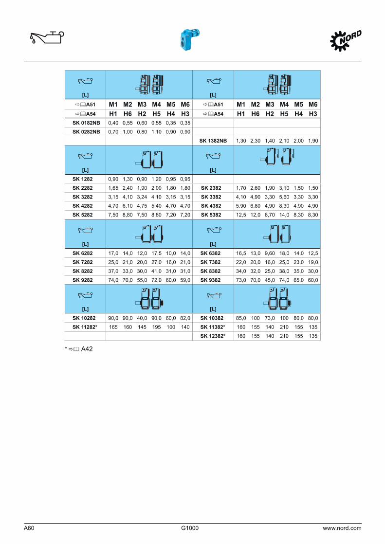
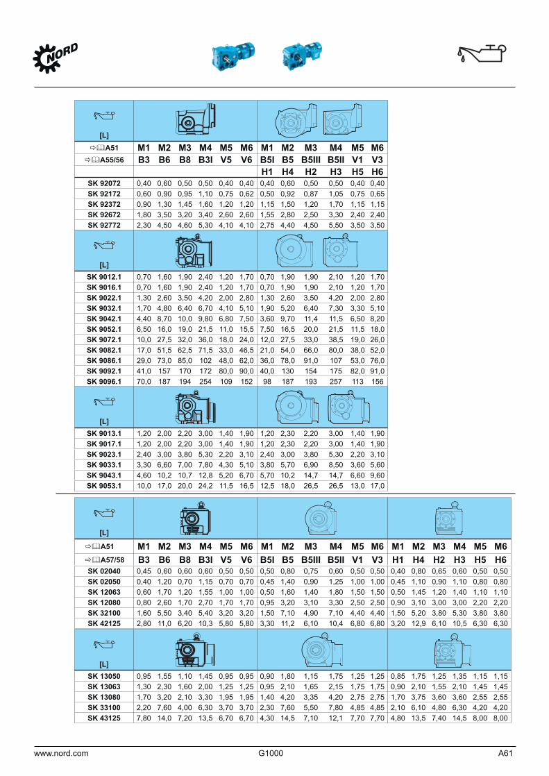
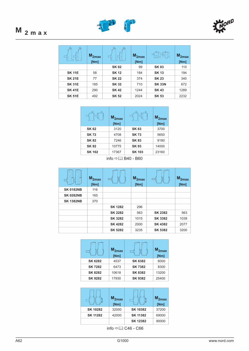
M2max
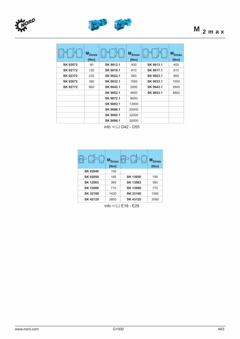
M2max
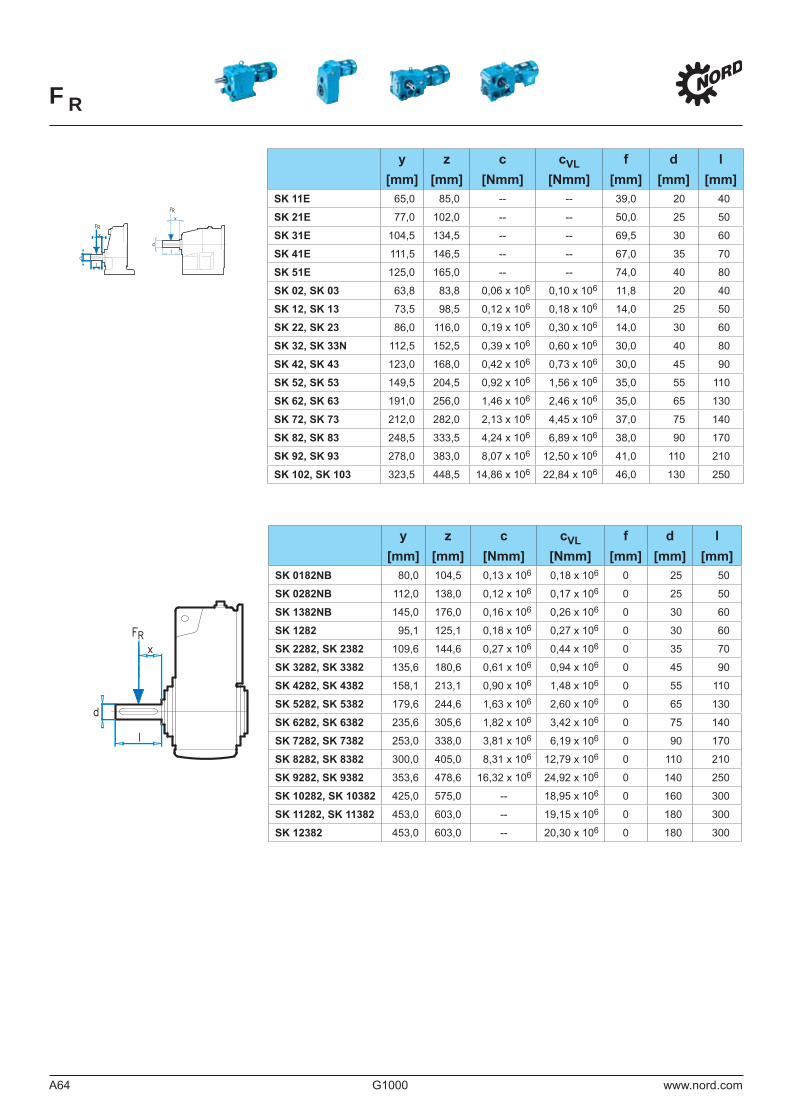
FR
dl
F
dl
RF
x
x
RR
RRFF
dd
ll
xx
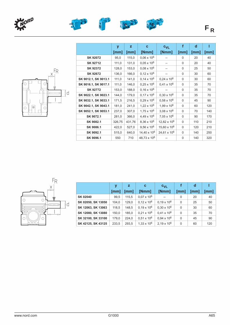
ddll
RRFFxx
ddll
RRFFxx
FR
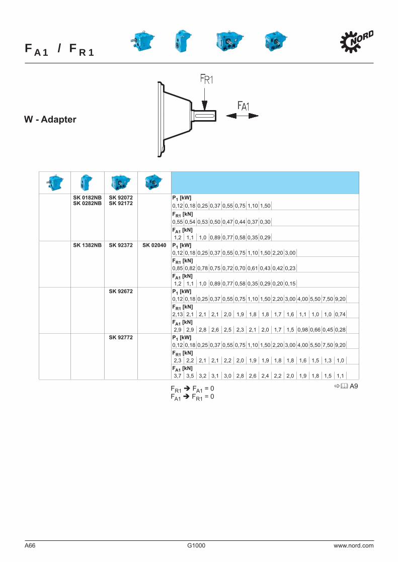
FA1 / FR1
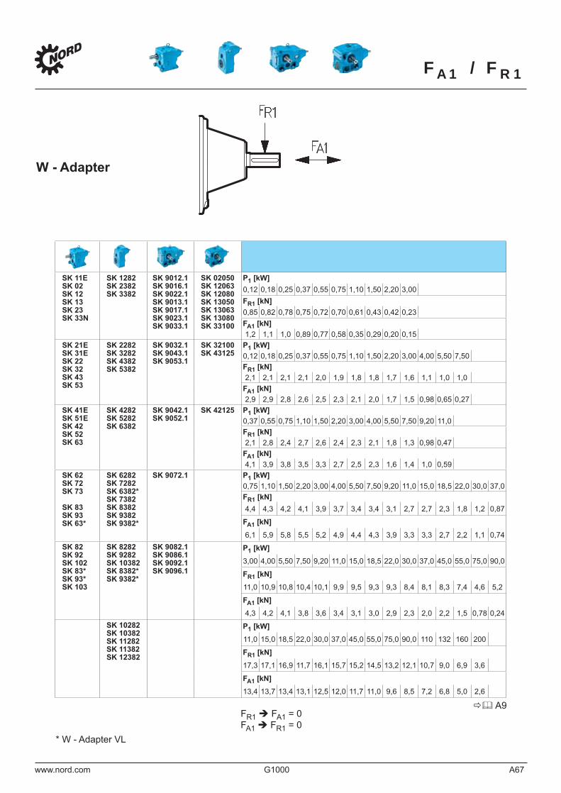
FA1 / FR1
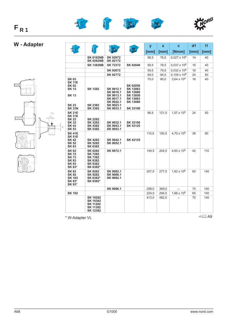
FR1
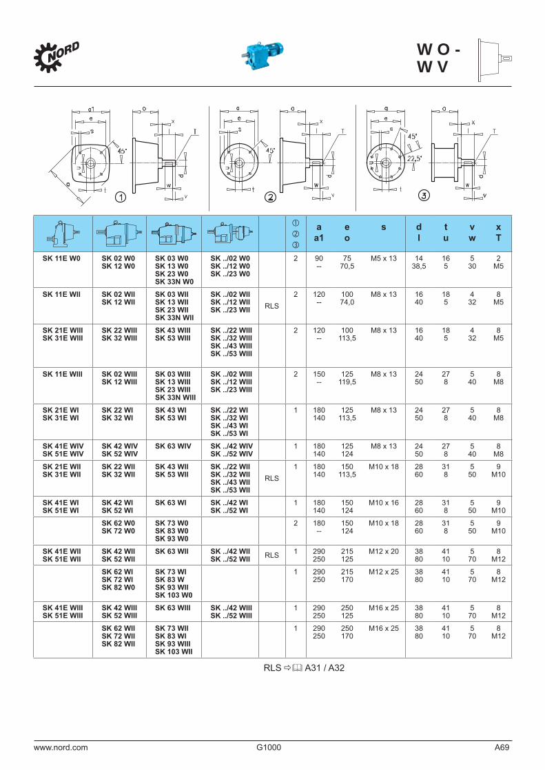
WO-WV
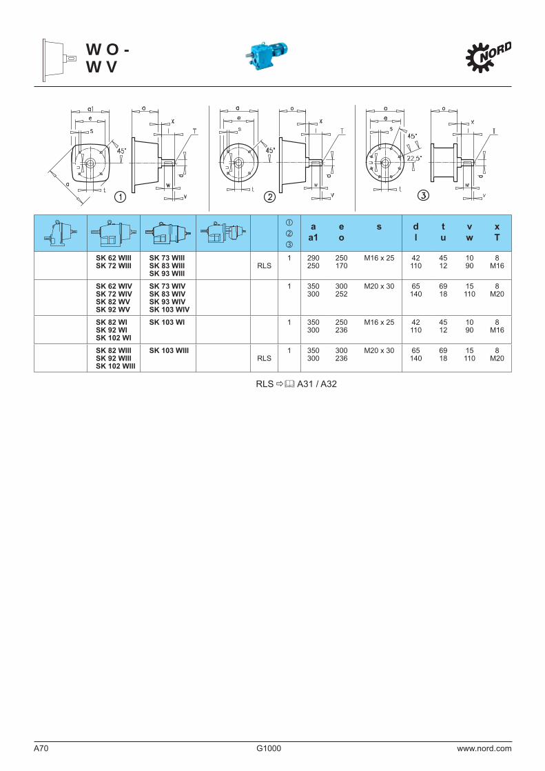
WO-WV
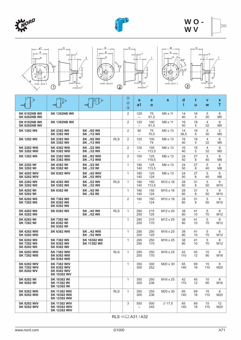
WO-WV
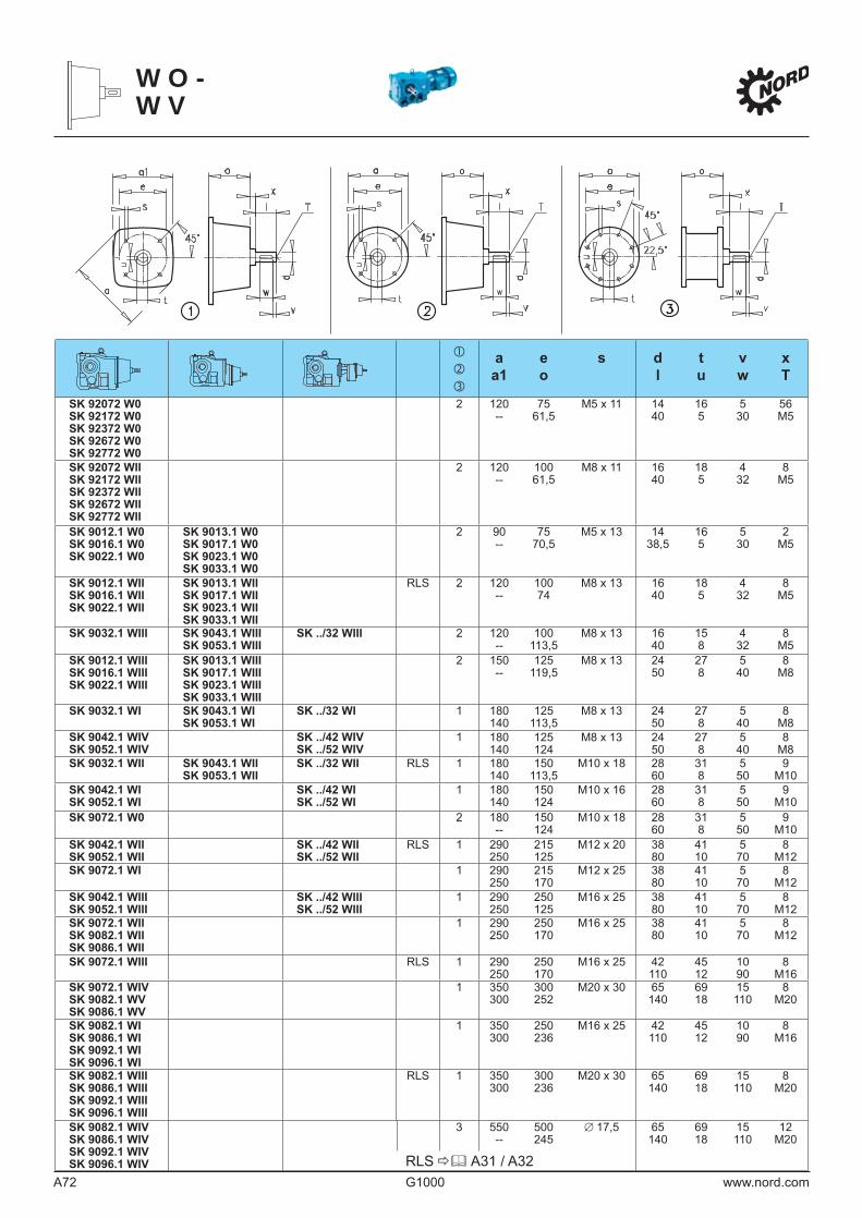
WO-WV
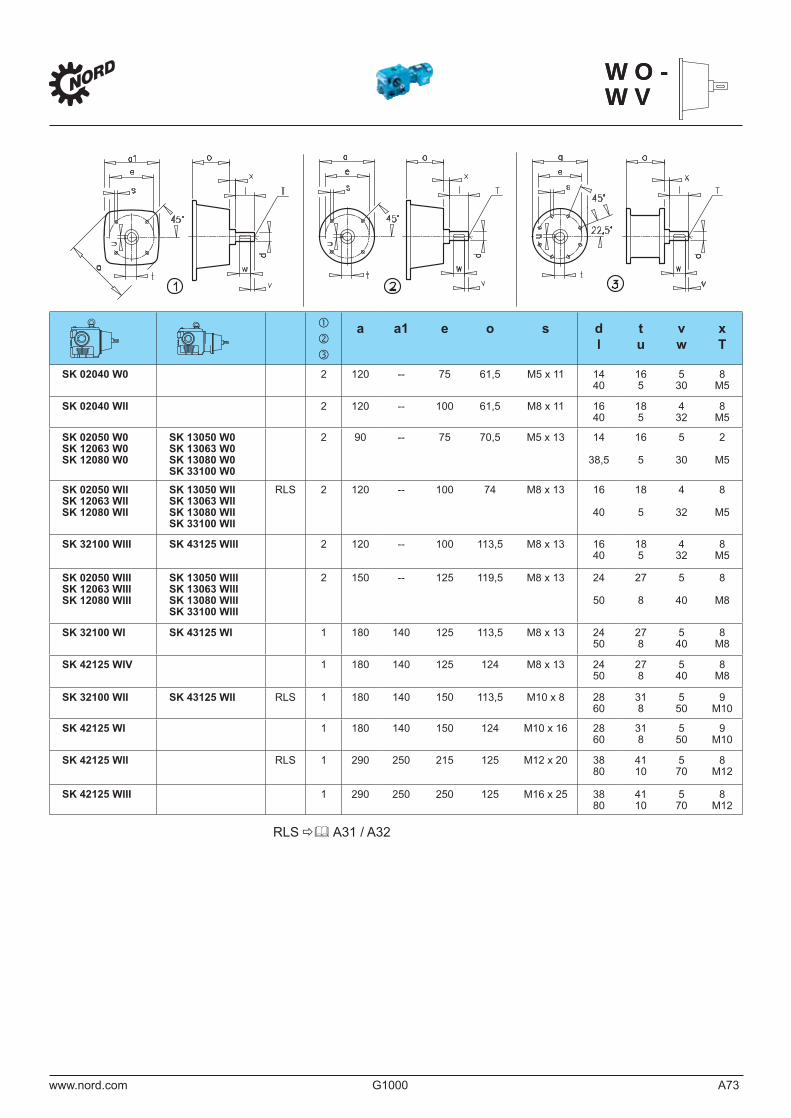
WO-WVWO-WV
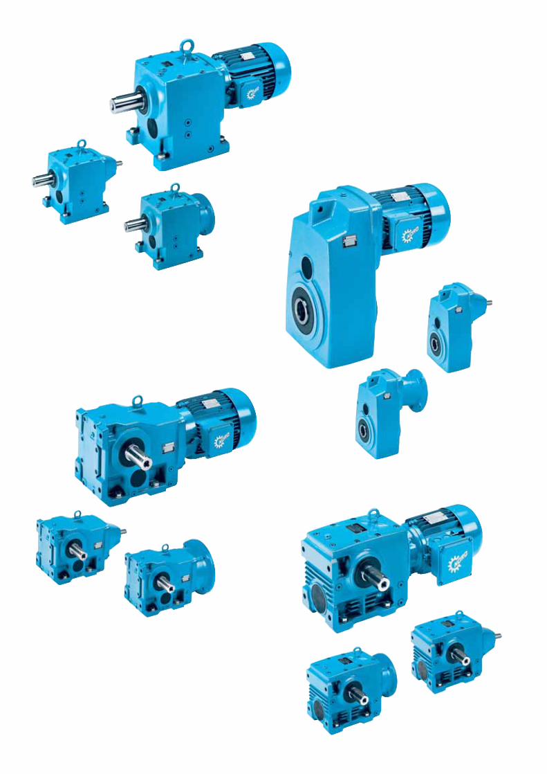
Explosion protection / ATEX Requirements What are the details?
GBwww.nord.com G1000 A75
Potentially explosive gas or dust atmospheres are found in various areas of industry and manual trade. These are mostly caused by oxygen mixing with ignitable gases or airborne or settled ignitable dust. Therefore, electrical and mechanical equipment for explosion-risk areas is subject to special national and international standards and guidelines. Explosion protection regulations are aimed at protecting persons and objects from potential explosion hazards. Integrated explosion protection indicates that explosion protection measures should be taken in a defined order:
- Rules for preventing the development of potentially explosive atmospheres- Avoiding ignition of potentially explosive atmospheres- Keeping the impact of an explosion within safe limits
Mechanical and electrical equipment is constructed with a view to avoiding ignition and/or limiting its impact. This is where explosion protection requirements are implemented.
The term ATEX which is frequently used for explosion protection consists of the first letters of an old French directive title: “Atmospheres Explosives”. On the basis of this, the European Parliament issued EU directive 94/9/EC in March 1994, equalizing the legal requirements for equipment and protective systems intended for use in potentially explosive atmospheres. This directive is also referred to as the “equipment directive” in order to distinguish it from the workplace directive 99/92/EC for companies with explosion-risk areas. As of 1 July, 2003, directive 94/9/EC for explosion-proof applications has been adopted exclusively and is mandatory throughout the EU. Basic safety and health requirements are met by drawing on harmonized standards, examples of which are listed below:
Standards for electrical equipment:DIN EN 60 079 - 0 General requirementsDIN EN 60 079 - 1 Flameproof enclosure “d”DIN EN 60 079 - 7 Increased safety “e” DIN EN 60 079 - 15 Non sparking “n” DIN EN 50281 - Combustible dust
Standards for mechanical equipmentSeries of standards EN 13463especially EN 13463-1 Basic methodand EN 13463-5 Protection by constructional safety
Directive 94/9/EC means that besides special motors, mechanical equipment and protective systems must also meet specific requirements. Furthermore, quality assurance was added as an additional safety measure. Every manufacturer of electrical EX equipment (Category 1 or 2) must submit to auditing. Auditing is conducted by a “Notified Body”. → cf. the Getriebebau NORD certificate at page A80.
“Equipment” and “Component” Directive 94/9/EC defines “equipment” as “machines, apparatus…which, separately or jointly, are intended for the generation, transfer, storage, measurement, control and conversion of energy for the processing of material and which are capable of causing an explosion through their own potential sources of ignition”. Therefore, all gear units and motors supplied by NORD for explosion protection are defined as equipment.“Components” are defined as “any item essential to the safe functioning of equipment and protective systems but with no autonomous function”.
The term “Equipment Group”The ATEX directive distinguishes two equipment groups: Group I applies to equipment intended for use in mines, whereas group II applies to all other uses of equipment. Thus, for most applications, the EX protection declaration on the name plate begins with a “II”, so that special features of Group I systems shall not be taken into consideration any further.
Equipment category (e.g.: 2G, 3G, 2D or 3D)The equipment category indicates instantly whether the equipment is intended for use in gas atmospheres (G = gas) or dust atmospheres (D = dust). The choice of a category number is based on the zone defined for the operating environment of a gear motor. Here, it is important to consider whether the equipment is exposed to potentially explosive atmospheres
- infrequently (Zone 2 for gas, Zone 22 for dust),- occasionally (Zone 1 for gas, Zone 21 for dust),- continuously, for long periods or frequently (Zone 0 for gas, Zone 20 for dust)
As an exception, a Category 2D motor is also required for Zone 22 in the case of conductive dust, e.g. coal dust. For Zone 20 and Zone 0 environments, e.g. inside pipelines, electrical gear units are usually not available. This is a typical domain for other solutions such as compressed-air technologies. This is also the reason why NORD does not supply any gear units for category 1.
Explosion protection / ATEX Requirements What are the details?
GB A76 G1000 www.nord.com
Zone categorization for combustible gases, vapours and mists Zone 0:The area where a potentially explosive atmosphere caused by a mixture of air with combustible gases, vapours or mists is present continuously, for long periods or frequently.Zone 1:The area where a potentially explosive atmosphere caused by a mixture of air with combustible gases, vapours or mists is likely to occur occasionally during normal operation.Zone 2:The area where a potentially explosive atmosphere caused by a mixture of air with combustible gases, vapours or mists is unlikely to occur or only occurs for short periods during normal operation.
Zone categorization for combustible dustZone 20:The area where a potentially explosive atmosphere in the form of a cloud made up of combustible dust contained in the air is present continuously, for long periods or frequently.Zone21:The area where a potentially explosive atmosphere in the form of a cloud made up of combustible dust contained in the air can occur occasionally during normal operation.Zone 22:The area where a potentially explosive atmosphere in the form of a cloud made up of combustible dust contained in the air is unlikely to occur or only occurs for short periods during normal operation.
Protection type Following the equipment category and the risk category, the lower case characters in the EX protection declaration indicate the exact protection types of a piece of equipment. The main protection options to be considered in the case of drives are enclosures and construction measures. Depending on the danger zone and equipment category, different solutions are premissible and possible.Protection type
Electrical: Short reference:Flameproof enclosure d
Increased safety e
Non sparking n
Mechanical: Short reference:Constructional safety c
Liquid immersion k
Constructional safety, e.g. “c”A gear unit usually becomes an EX-proof system on account of the constructional safety measures incorporated in its design. The requirements for technical components are set out in the highly informative EN 13463-5 which describes protection type “c”. Some drive manufacturers tend to be sceptical as to whether liquid immersion according to protection type “k” is a suitable alternative form of explosion protection for drives. A risk of sparks cannot be excluded, e.g. in cases of breakage, at least within systems that are only partly immersed in oil.
Increased safety (Ex e)For motors falling into equipment categories 2G and 3G, i.e. EX zones 1 and 2, sparks and impermissible temperatures are avoided in accordance with protection type “e” (Increased safety). This is achieved by constructing fans and fan hoods, as well as by proper storage and terminal boxes. One of the characteristic features of such arrangements is the low surface resistance of plastic fans (depending on the fan circumference speed). There are considerable air gaps between rotating parts and large air and creepage distances in the terminal box.When choosing a model, you have to be aware that drives falling under protection type “e” often have less output power than the corresponding standard motors. These motors have different windings to comparable motors designed for non Ex areas. In practice, this results in lower performance levels. These motors are usually used for temperatures up to Temperature class T3.
Flameproof enclosure (Ex d and Ex de)Protection type “de” offers a different kind of protection:These motors are constructed so as to bear up against explosions in the internal space of the motor and prevent a transmission of the explosion to the surrounding atmosphere. Such motors are fitted with stronger walls to contain the excess pressure developing inside them during ignition. These systems also have fans of protection type “e”.The drives offer the same rated power as non-EX-proof motors and can normally be used in the same way as gear motors with protection type “e” in Zone 1 and 2. These motors are frequently used for inverter operations, brakes, encoders and/or when a very high degree of safety is required. Typically, the flameproof motors supplied by NORD meet the requirements of Explosion group IIC and Temperature class T4.
Zone Categorization - What and Where
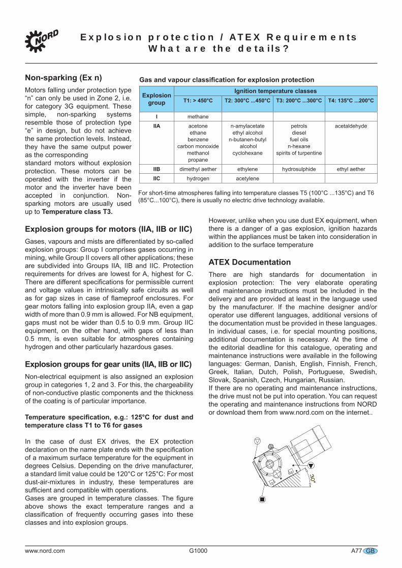
Explosion protection / ATEX Requirements What are the details?
GBwww.nord.com G1000 A77
Non-sparking (Ex n)Motors falling under protection type “n” can only be used in Zone 2, i.e. for category 3G equipment. These simple, non-sparking systems resemble those of protection type “e” in design, but do not achieve the same protection levels. Instead, they have the same output power as the correspondingstandard motors without explosion protection. These motors can be operated with the inverter if the motor and the inverter have been accepted in conjunction. Non-sparking motors are usually used up to Temperature class T3.
Explosion groups for motors (IIA, IIB or IIC)Gases, vapours and mists are differentiated by so-called explosion groups: Group I comprises gases occurring in mining, while Group II covers all other applications; these are subdivided into Groups IIA, IIB and IIC. Protection requirements for drives are lowest for A, highest for C. There are different specifications for permissible current and voltage values in intrinsically safe circuits as well as for gap sizes in case of flameproof enclosures. For gear motors falling into explosion group IIA, even a gap width of more than 0.9 mm is allowed. For NB equipment, gaps must not be wider than 0.5 to 0.9 mm. Group IIC equipment, on the other hand, with gaps of less than 0.5 mm, is even suitable for atmospheres containing hydrogen and other particularly hazardous gases.
Explosion groups for gear units (IIA, IIB or IIC)Non-electrical equipment is also assigned an explosion group in categories 1, 2 and 3. For this, the chargeability of non-conductive plastic components and the thickness of the coating is of particular importance.
Temperature specification, e.g.: 125°C for dust and temperature class T1 to T6 for gases
In the case of dust EX drives, the EX protection declaration on the name plate ends with the specification of a maximum surface temperature for the equipment in degrees Celsius. Depending on the drive manufacturer, a standard limit value could be 120°C or 125°C: For most dust-air-mixtures in industry, these temperatures are sufficient and compatible with operations.Gases are grouped in temperature classes. The figure above shows the exact temperature ranges and a classification of frequently occurring gases into these classes and into explosion groups.
However, unlike when you use dust EX equipment, when there is a danger of a gas explosion, ignition hazards within the appliances must be taken into consideration in addition to the surface temperature
ATEX DocumentationThere are high standards for documentation in explosion protection: The very elaborate operating and maintenance instructions must be included in the delivery and are provided at least in the language used by the manufacturer. If the machine designer and/or operator use different languages, additional versions of the documentation must be provided in these languages. In individual cases, i.e. for special mounting positions, additional documentation is necessary. At the time of the editorial deadline for this catalogue, operating and maintenance instructions were available in the following languages: German, Danish, English, Finnish, French, Greek, Italian, Dutch, Polish, Portuguese, Swedish, Slovak, Spanish, Czech, Hungarian, Russian.If there are no operating and maintenance instructions, the drive must not be put into operation. You can request the operating and maintenance instructions from NORD or download them from www.nord.com on the internet..
30°
Gas and vapour classification for explosion protection
Explosion group
Ignition temperature classesT1: > 450°C T2: 300°C ...450°C T3: 200°C ...300°C T4: 135°C ...200°C
I methane
IIA acetoneethane
benzenecarbon monoxide
methanolpropane
n-amylacetateethyl alcohol
n-butanen-butyl alcohol
cyclohexane
petrolsdiesel
fuel oilsn-hexane
spirits of turpentine
acetaldehyde
IIB dimethyl aether ethylene hydrosulphide ethyl aether
IIC hydrogen acetylene
For short-time atmospheres falling into temperature classes T5 (100°C ...135°C) and T6 (85°C...100°C), there is usually no electric drive technology available.
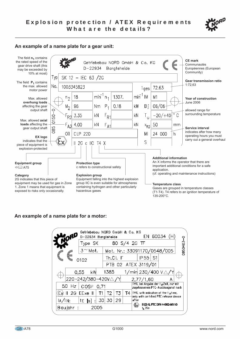
Explosion protection / ATEX Requirements What are the details?
GB A78 G1000 www.nord.com
An example of a name plate for a gear unit:
An example of a name plate for a motor:
Typ
D-22934 Bargteheide
Getriebebau NORD GmbH & Co. KG
No.
n
M
SK 12 - IEC 63 /2G
F
085 0150-0
2
R2
FA2 FA1
FR1
Nm
kN
kN
min-1
1n min-1
kW
kN
kN
IM
Bj
°C
i ges
MI h
P1
Tu
2
R2x mm
Oil
S
1003345823
18
96
3.35
4.00
CLP 220
1307.
0.18
72.63
M1
06/06
-20/+40
50
24 000
II 2G c IIC T4 X
The field n1 contains the rated speed of the
gear drive shaft (this may be exceeded by
10% at most)
The field P1 contains the max. allowed
motor power
Max. allowed overhung loads affecting the gear
output shaft
Max. allowed axial loads affecting the
gear output shaft
EX logoindicates that the
piece of equipment is explosion-protected
CE markCommunautés Européennes (European Community)
Gear transmission ratio1:72,63
Year of constructionJune 2006
allowed range for surrounding temperature
Service intervalindicates after how many operating hours you must carry out a general overhaul
Additional informationAn X informs the operator that there are important additional conditions for a safe application. (cf. operating and maintenance instructions)
Temperature classGases are grouped in temperature classes (T1-T4). T4 refers to an ignition temperature of 135-200°C.
Protection typec refers to constructional safety
Equipment group A75
Category2G indicates that this piece of equipment may be used for gas in Zone 1. Zone 1 means that equipment is exposed to risks only occasionally.
Explosion groupEquipment falling into the highest explosion group IIC is even suitable for atmospheres containing hydrogen and other particularly hazardous gases
V /Y
1/min
PTB ATEX
I /I
Hz COS
Th.Cl. F
3 Mot.
Type SK
Mot. Nr.:
kW
IP
0850403-0
S1
Getriebebau NORD GmbH & Co. KG
D-22934 Bargteheide EN 60034 (H)
Ex II 2G EExe II
A N:
Baujahr :
0102
T1 T2 T3 T4
E [s] :t
A
V /Y
80 S/4 2G TF
33091170/0548/005
55
02 3119/01
0,55 1385 230/400
220-242/380-420
50 0,71
30 30 29
2005
TMS, bei Angabe der t -Zeit, nur mit
zugelassenem PTC-Auslösegerät nach
II (2) G, PTC DIN 44082-M110t 35s
A
A
ATMS, with indication of the t -time,
only with certified PTC release device
after
2,77/1,60
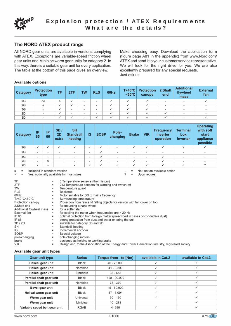
Explosion protection / ATEX Requirements What are the details?
GBwww.nord.com G1000 A79
The NORD ATEX product rangeAll NORD gear units are available in versions complying with ATEX. Exceptions are variable-speed friction wheel gear units and Minibloc worm gear units for category 2. In this way, there is a suitable gear unit for every application. The table at the bottom of this page gives an overview.
Make choosing easy. Download the application form (figure page A81 in the appendix) from www.Nord.com/ATEX and send it to your customer service representative. We will look for the right drive for you. We are also excellently prepared for any special requests.Just ask us.
Available options
Category Protectiontype TF 2TF TW RLS 60Hz T>40°C
<60°CProtection
canopy2.Shaft
end
Additionalflywheel
mass
Externalfan
2G de s - - - -2G e - - - - -3G n - - - - - -2D - - - - - -3D - - -
Category IP65
IP66
3D / 2D
extra
SH Standstillheating
IG SOSP Pole-changing Brake VIK
Frequencyinverter
operation
Terminal box
inverter
Operatingwith soft
start appliancepossible
2G ?2G - - - - - - - - -3G - - - - - - - - - -2D - S - - - - - -2D - - - ?
s = Included in standard version - = Not, not an available option = Yes, optionally available for most sizes ? = Upon request
TF = 3 Temperature sensors (thermistors) 2TF = 2x3 Temperature sensors for warning and switch-offTW = Temperature guardRLS = Backstop60Hz = Motor suitable for 60Hz mains frequencyT>40°C<60°C = Surrounding temperatureProtection canopy = Protection from rain and falling objects for version with fan cover on top2.Shaft end = for mounting a hand wheel Additional flywheel mass = for a softer startExternal fan = for cooling the motor when frequencies are < 20 HzIP 65 = optimal protection from foreign matter (prescribed in cases of conductive dust)IP 66 = strong protection from dust and water entering the unit 3D / 2D = suitable for category 3D and 2DSH = Standstill heatingIG = Incremental encoderSOSP = Special voltagepole-changing = pole-changing motorsbrake = designed as holding or working brakeVIK = Design acc. to the Association of the Energy and Power Generation Industry, registered society
Available gear unit typesGear unit type Series Torque from - to [Nm] available in Cat.2 available in Cat.3Helical gear unit Block 46 - 23.000Helical gear unit Nordbloc 41 - 3.200Helical gear unit Standard 38 - 658
Parallel shaft gear unit Block 128 - 90.000Parallel shaft gear unit Nordbloc 73 - 370
Bevel gear unit Block 45 - 50.000Helical worm gear unit Block 37 - 3.094
Worm gear unit Universal 30 - 160Worm gear unit Minibloc 10 - 283
Variable speed belt gear unit RGAE 4- 690
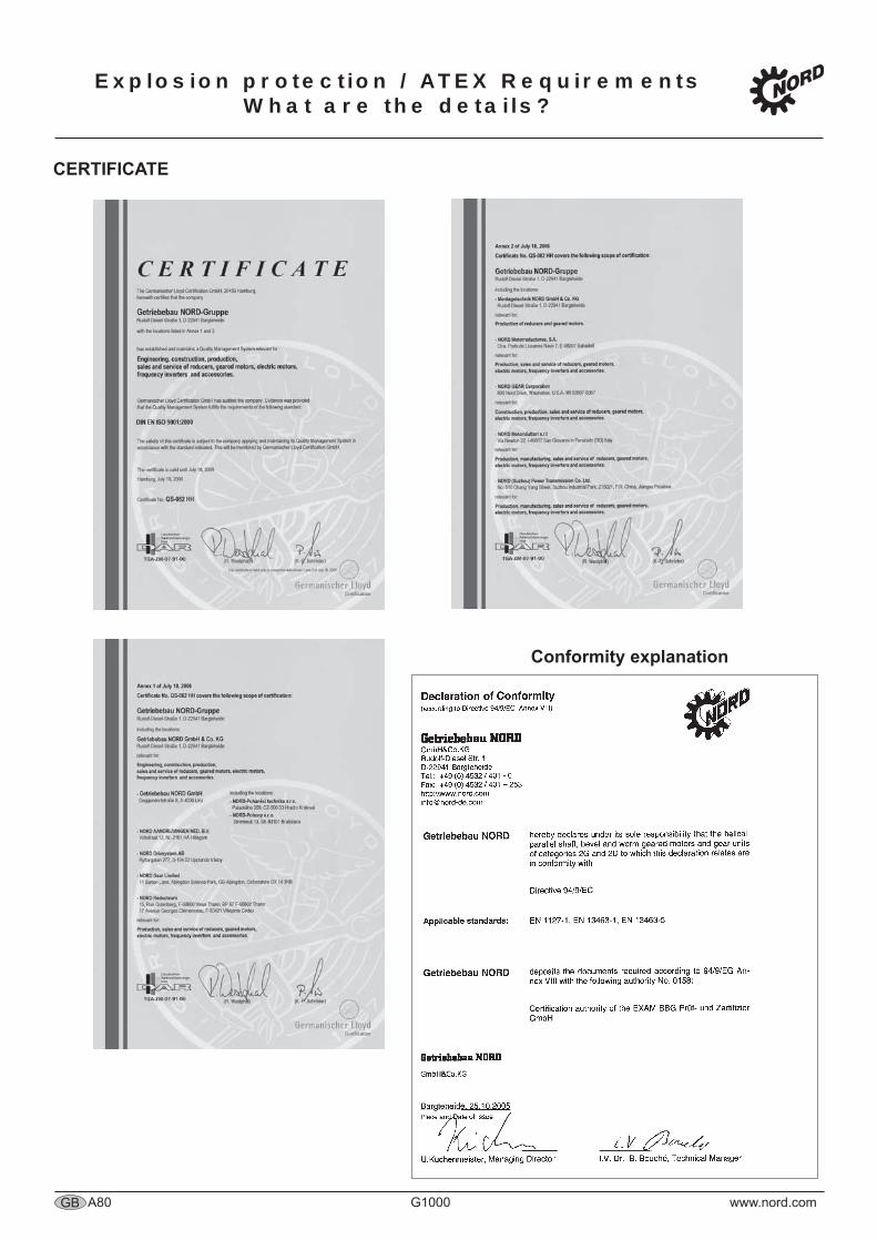
Explosion protection / ATEX Requirements What are the details?
GB A80 G1000 www.nord.com
CERTIFICATE
Conformity explanation