Embed Size (px)
Citation preview
1© 2003, Cisco Systems, Inc. All rights reserved.Jan 2003
Improving Availability in Multilayer Switched Networks
222© 2003, Cisco Systems, Inc. All rights reserved.Jan 2003
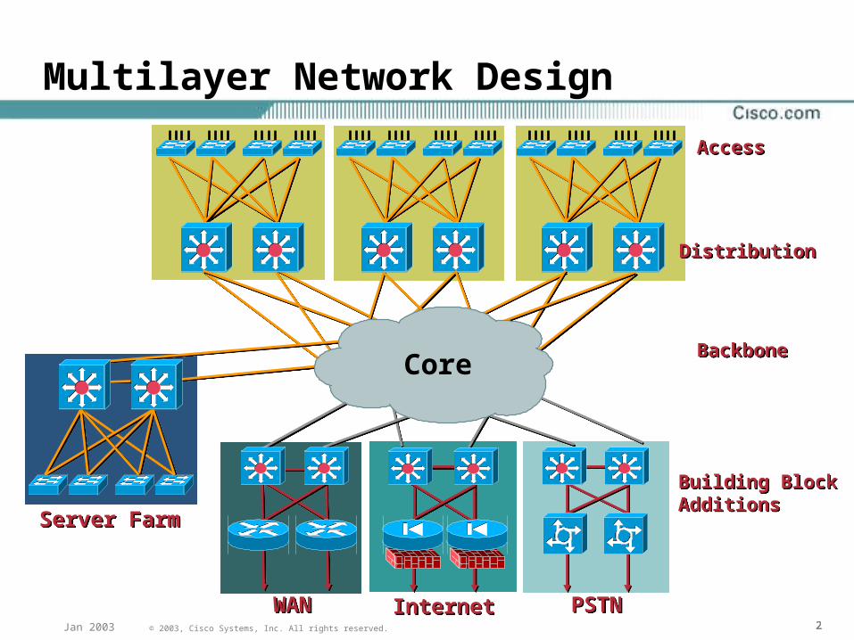
Multilayer Network Design
DistributionDistribution
AccessAccess
BackboneBackbone
WANWAN InternetInternet PSTNPSTN
Server FarmServer Farm
Building BlockAdditionsBuilding BlockAdditions
Core
333© 2003, Cisco Systems, Inc. All rights reserved.Jan 2003
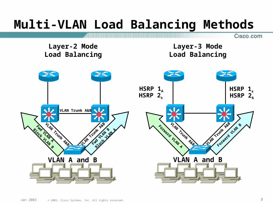
Multi-VLAN Load Balancing Methods
VLAN A and B
VLAN Trunk A&B
VLAN Trunk A&B VLAN Tru
nk A&B
Fwd VLAN B
Block
VLAN A
Fwd VLAN A
Block VLAN B
Layer-2 ModeLoad Balancing
VLAN A and B
VLAN Trunk A&B VLAN Tru
nk A&B
Forwar
d VLAN BForward VLAN A
Layer-3 ModeLoad Balancing
HSRP 1A
HSRP 2s
HSRP 1s
HSRP 2A
444© 2003, Cisco Systems, Inc. All rights reserved.Jan 2003
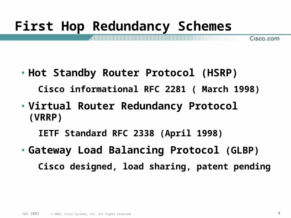
First Hop Redundancy Schemes
• Hot Standby Router Protocol (HSRP)
Cisco informational RFC 2281 ( March 1998)
• Virtual Router Redundancy Protocol (VRRP)
IETF Standard RFC 2338 (April 1998)
• Gateway Load Balancing Protocol (GLBP)
Cisco designed, load sharing, patent pending
555© 2003, Cisco Systems, Inc. All rights reserved.Jan 2003
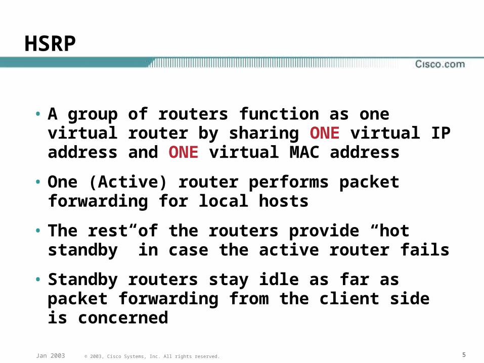
HSRP
• A group of routers function as one virtual router by sharing ONE virtual IP address and ONE virtual MAC address
• One (Active) router performs packet forwarding for local hosts
• The rest of the routers provide “hot standby” in case the active router fails
• Standby routers stay idle as far as packet forwarding from the client side is concerned
666© 2003, Cisco Systems, Inc. All rights reserved.Jan 2003
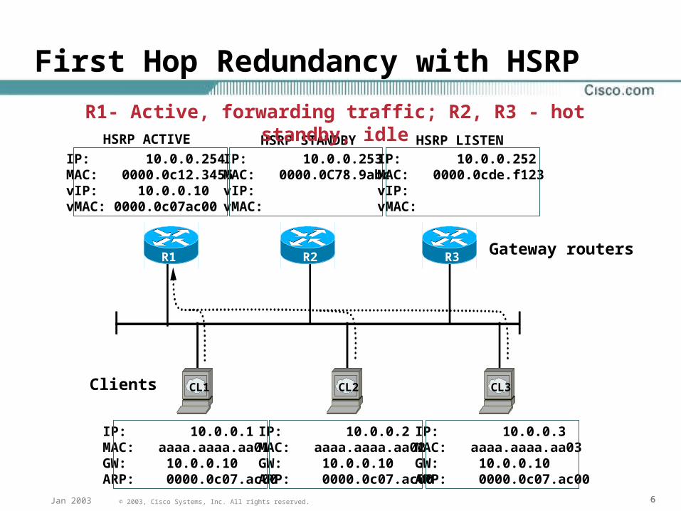
First Hop Redundancy with HSRP
Gateway routers
CL1 CL2 CL3
HSRP ACTIVE HSRP STANDBY HSRP LISTEN
Clients
R1 R2 R3
R1- Active, forwarding traffic; R2, R3 - hot standby, idle
IP: 10.0.0.254MAC: 0000.0c12.3456vIP: 10.0.0.10vMAC: 0000.0c07ac00
IP: 10.0.0.253MAC: 0000.0C78.9abcvIP:vMAC:
IP: 10.0.0.252MAC: 0000.0cde.f123vIP:vMAC:
IP: 10.0.0.1MAC: aaaa.aaaa.aa01GW: 10.0.0.10ARP: 0000.0c07.ac00
IP: 10.0.0.2MAC: aaaa.aaaa.aa02GW: 10.0.0.10ARP: 0000.0c07.ac00
IP: 10.0.0.3MAC: aaaa.aaaa.aa03GW: 10.0.0.10ARP: 0000.0c07.ac00
777© 2003, Cisco Systems, Inc. All rights reserved.Jan 2003
VRRP
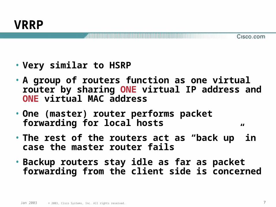
• Very similar to HSRP
• A group of routers function as one virtual router by sharing ONE virtual IP address and ONE virtual MAC address
• One (master) router performs packet forwarding for local hosts
• The rest of the routers act as “back up” in case the master router fails
• Backup routers stay idle as far as packet forwarding from the client side is concerned
888© 2003, Cisco Systems, Inc. All rights reserved.Jan 2003
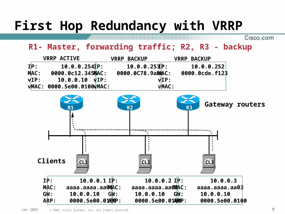
First Hop Redundancy with VRRP
Gateway routers
CL1 CL2 CL3
VRRP ACTIVE VRRP BACKUP VRRP BACKUP
Clients
R1 R2 R3
R1- Master, forwarding traffic; R2, R3 - backup
IP: 10.0.0.254MAC: 0000.0c12.3456vIP: 10.0.0.10vMAC: 0000.5e00.0100
IP: 10.0.0.253MAC: 0000.0C78.9abcvIP:vMAC:
IP: 10.0.0.252MAC: 0000.0cde.f123vIP:vMAC:
IP: 10.0.0.1MAC: aaaa.aaaa.aa01GW: 10.0.0.10ARP: 0000.5e00.0100
IP: 10.0.0.2MAC: aaaa.aaaa.aa02GW: 10.0.0.10ARP: 0000.5e00.0100
IP: 10.0.0.3MAC: aaaa.aaaa.aa03GW: 10.0.0.10ARP: 0000.5e00.0100
999© 2003, Cisco Systems, Inc. All rights reserved.Jan 2003
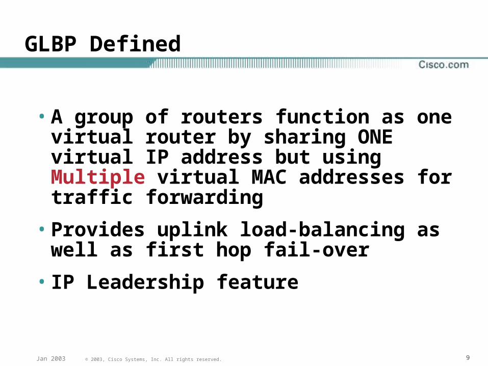
GLBP Defined
• A group of routers function as one virtual router by sharing ONE virtual IP address but using Multiple virtual MAC addresses for traffic forwarding
• Provides uplink load-balancing as well as first hop fail-over
• IP Leadership feature

101010© 2003, Cisco Systems, Inc. All rights reserved.Jan 2003
GLBP Requirements
• Allow traffic from a single common subnet to go through multiple redundant gateways using a single virtual IP address
• Provide upstream load-balancing by utilizing the redundant up-links simultaneously
• Eliminate the need to create multiple vLANs or manually divide clients for multiple gateway IP address assignment
• Preserve the same level of first-hop failure recovery capability as provided by HSRP
111111© 2003, Cisco Systems, Inc. All rights reserved.Jan 2003
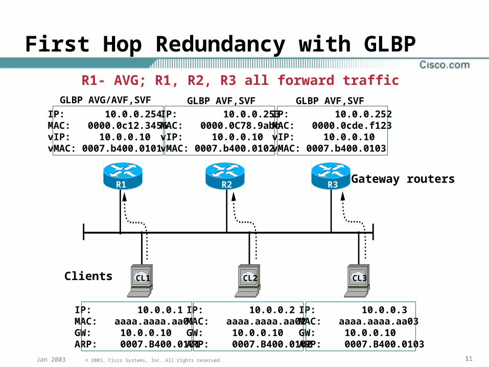
First Hop Redundancy with GLBP
Gateway routers
CL1 CL2 CL3
GLBP AVG/AVF,SVF GLBP AVF,SVF GLBP AVF,SVF
Clients
R1 R2 R3
R1- AVG; R1, R2, R3 all forward traffic
IP: 10.0.0.254MAC: 0000.0c12.3456vIP: 10.0.0.10vMAC: 0007.b400.0101
IP: 10.0.0.253MAC: 0000.0C78.9abcvIP: 10.0.0.10vMAC: 0007.b400.0102
IP: 10.0.0.252MAC: 0000.0cde.f123vIP: 10.0.0.10vMAC: 0007.b400.0103
IP: 10.0.0.1MAC: aaaa.aaaa.aa01GW: 10.0.0.10ARP: 0007.B400.0101
IP: 10.0.0.2MAC: aaaa.aaaa.aa02GW: 10.0.0.10ARP: 0007.B400.0102
IP: 10.0.0.3MAC: aaaa.aaaa.aa03GW: 10.0.0.10ARP: 0007.B400.0103
121212© 2003, Cisco Systems, Inc. All rights reserved.Jan 2003
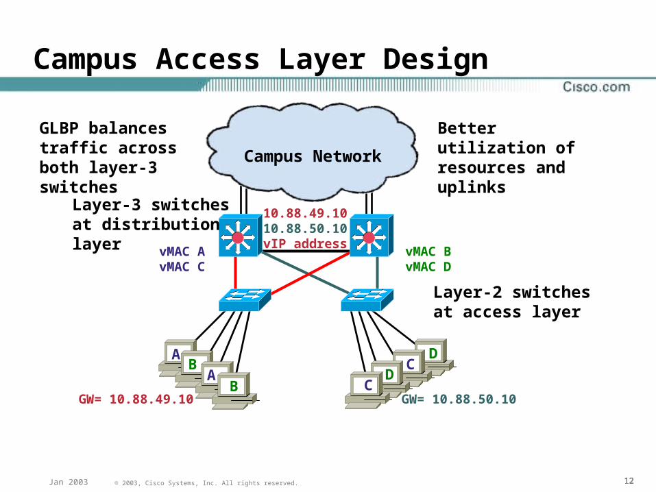
Campus Access Layer Design
Campus Network
GW= 10.88.50.10GW= 10.88.49.10C
CA
A
D
DB
B
Layer-3 switches at distribution layer
Layer-2 switches at access layer
Better utilization of resources and uplinks
GLBP balances traffic across both layer-3 switches
10.88.49.1010.88.50.10vIP address
vMAC AvMAC C
vMAC BvMAC D
131313© 2003, Cisco Systems, Inc. All rights reserved.Jan 2003
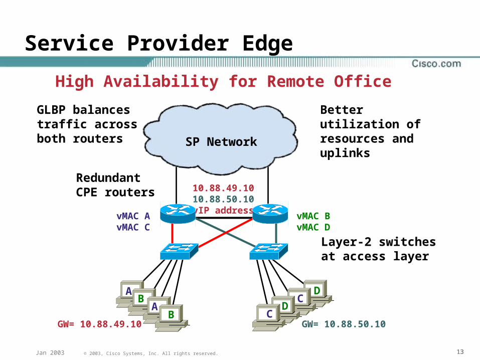
Service Provider Edge
10.88.49.1010.88.50.10vIP address
GW= 10.88.49.10C
CA
A
D
DB
B
RedundantCPE routers
Layer-2 switches at access layer
Better utilization of resources and uplinks
GLBP balances traffic across both routers SP Network
High Availability for Remote Office
GW= 10.88.50.10
vMAC AvMAC C
vMAC BvMAC D
141414© 2003, Cisco Systems, Inc. All rights reserved.Jan 2003
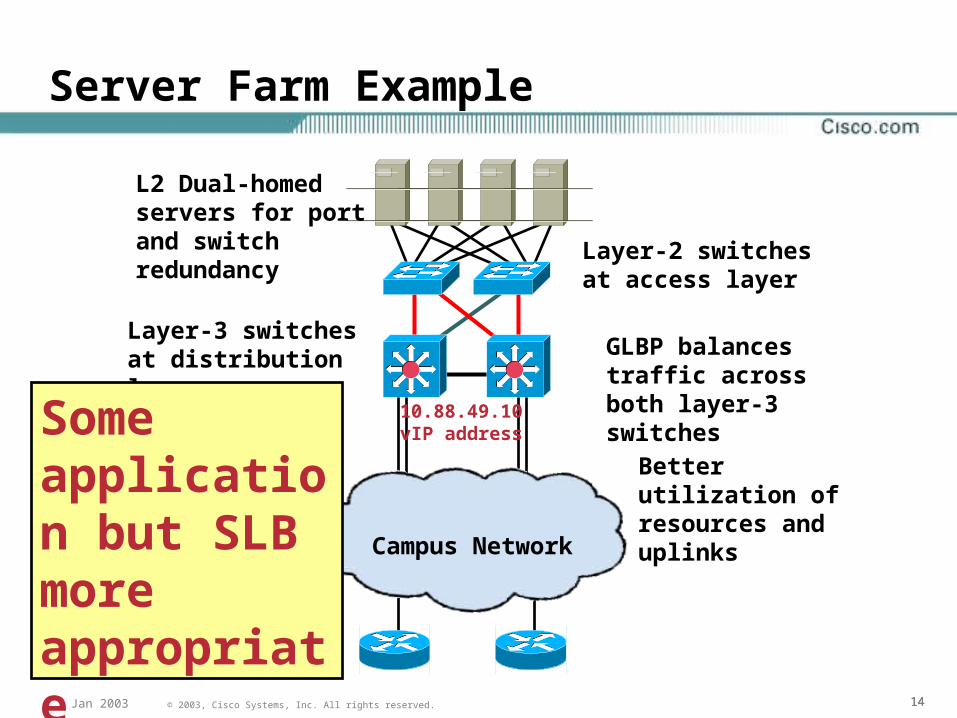
Server Farm Example
Campus Network
L2 Dual-homed servers for port and switch redundancy Layer-2 switches at
access layer
Layer-3 switches at distribution layer GLBP balances
traffic across both layer-3 switches
Better utilization of resources and uplinks
10.88.49.10vIP addressSome
application but SLB more appropriate
151515© 2003, Cisco Systems, Inc. All rights reserved.Jan 2003
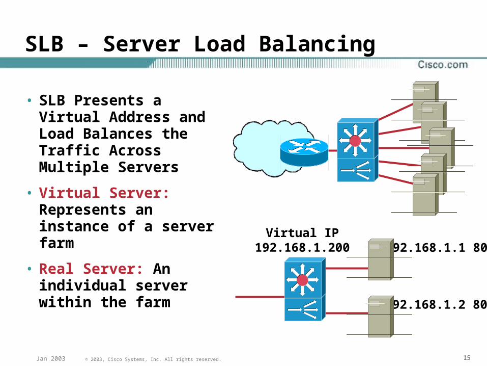
SLB – Server Load Balancing
• SLB Presents a Virtual Address and Load Balances the Traffic Across Multiple Servers
• Virtual Server: Represents an instance of a server farm
• Real Server: An individual server within the farm
Virtual IP192.168.1.200 192.168.1.1 80
192.168.1.2 80
161616© 2003, Cisco Systems, Inc. All rights reserved.Jan 2003
SLB Benefits
• High performance is achieved by distributing client requests across a cluster of servers.
• Administration of server applications is easierClients know only about virtual servers
No administration is required for real server changes
Maintenance with continuous availability is achieved by allowing physical (real) servers to be transparently placed in or out of service
• Security of the real server is provided because its address is never announced to the external network
Users are familiar only with the virtual IP address
Filtering of unwanted traffic can be based on both IP address and IP port numbers
171717© 2003, Cisco Systems, Inc. All rights reserved.Jan 2003
MSFC2 High Availability Features
• Provides multilayer switching and routing services between switched VLANs
• Dependent on Supervisor
Supervisor reset or failure will reset the MSFC2
• Operates in Dual Router Mode (DRM) or Single Router Mode (SRM)
181818© 2003, Cisco Systems, Inc. All rights reserved.Jan 2003
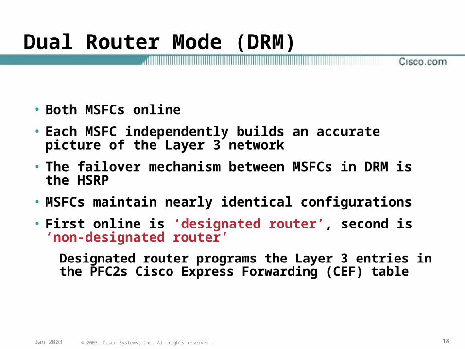
Dual Router Mode (DRM)
• Both MSFCs online
• Each MSFC independently builds an accurate picture of the Layer 3 network
• The failover mechanism between MSFCs in DRM is the HSRP
• MSFCs maintain nearly identical configurations
• First online is ‘designated router’, second is ‘non-designated router’
Designated router programs the Layer 3 entries in the PFC2s Cisco Express Forwarding (CEF) table
191919© 2003, Cisco Systems, Inc. All rights reserved.Jan 2003
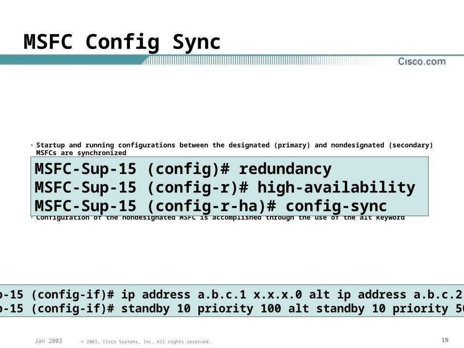
MSFC Config Sync
• Startup and running configurations between the designated (primary) and nondesignated (secondary) MSFCs are synchronized
• The following commands enable MSFC config-sync:
• Configuration of the nondesignated MSFC is accomplished through the use of the alt keyword
MSFC-Sup-15 (config)# redundancyMSFC-Sup-15 (config-r)# high-availability MSFC-Sup-15 (config-r-ha)# config-sync
MSFC-Sup-15 (config-if)# ip address a.b.c.1 x.x.x.0 alt ip address a.b.c.2 x.x.x.0MSFC-Sup-15 (config-if)# standby 10 priority 100 alt standby 10 priority 50
202020© 2003, Cisco Systems, Inc. All rights reserved.Jan 2003
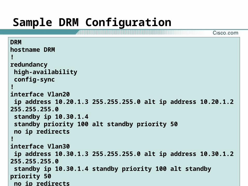
Sample DRM Configuration
DRMhostname DRM!redundancy high-availability config-sync !interface Vlan20 ip address 10.20.1.3 255.255.255.0 alt ip address 10.20.1.2 255.255.255.0 standby ip 10.30.1.4 standby priority 100 alt standby priority 50 no ip redirects!interface Vlan30 ip address 10.30.1.3 255.255.255.0 alt ip address 10.30.1.2 255.255.255.0 standby ip 10.30.1.4 standby priority 100 alt standby priority 50 no ip redirects !end
212121© 2003, Cisco Systems, Inc. All rights reserved.Jan 2003
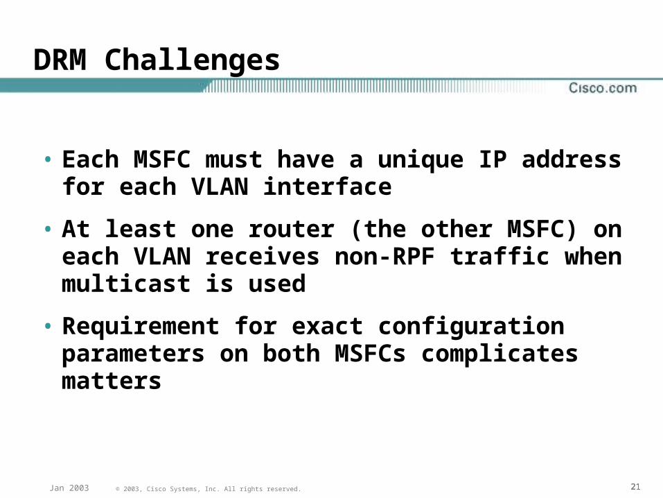
DRM Challenges
• Each MSFC must have a unique IP address for each VLAN interface
• At least one router (the other MSFC) on each VLAN receives non-RPF traffic when multicast is used
• Requirement for exact configuration parameters on both MSFCs complicates matters
222222© 2003, Cisco Systems, Inc. All rights reserved.Jan 2003
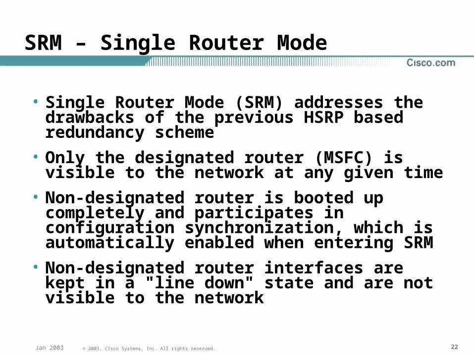
SRM – Single Router Mode
• Single Router Mode (SRM) addresses the drawbacks of the previous HSRP based redundancy scheme
• Only the designated router (MSFC) is visible to the network at any given time
• Non-designated router is booted up completely and participates in configuration synchronization, which is automatically enabled when entering SRM
• Non-designated router interfaces are kept in a "line down" state and are not visible to the network
232323© 2003, Cisco Systems, Inc. All rights reserved.Jan 2003
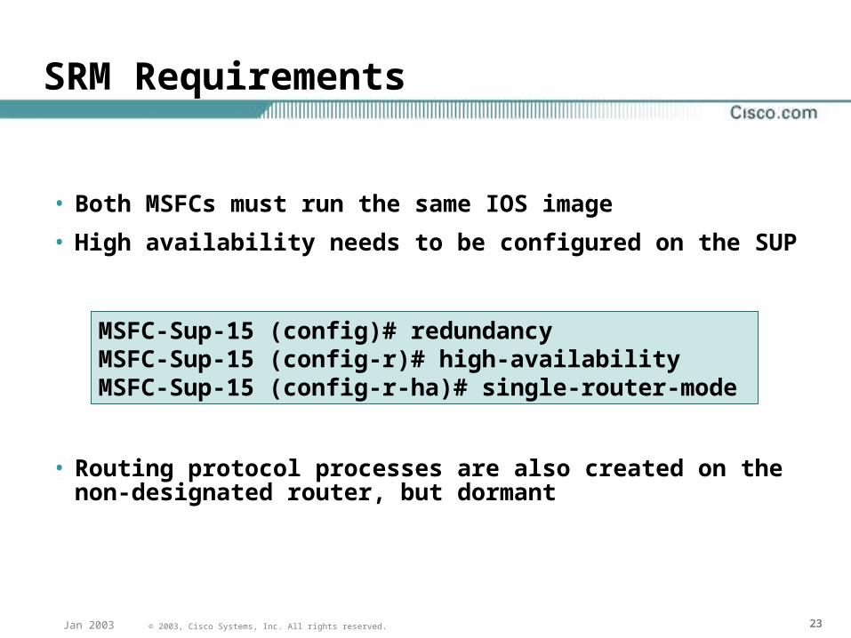
SRM Requirements
• Both MSFCs must run the same IOS image
• High availability needs to be configured on the SUP
• Routing protocol processes are also created on the non-designated router, but dormant
MSFC-Sup-15 (config)# redundancy MSFC-Sup-15 (config-r)# high-availability MSFC-Sup-15 (config-r-ha)# single-router-mode
242424© 2003, Cisco Systems, Inc. All rights reserved.Jan 2003
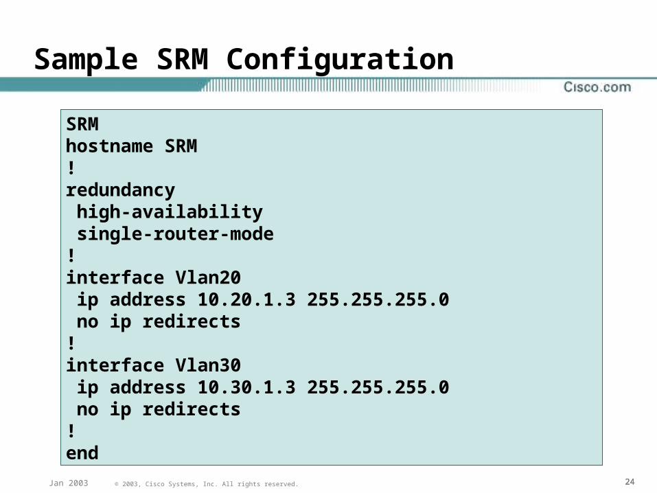
Sample SRM Configuration
SRMhostname SRM ! redundancy high-availability single-router-mode!interface Vlan20 ip address 10.20.1.3 255.255.255.0 no ip redirects !interface Vlan30 ip address 10.30.1.3 255.255.255.0 no ip redirects!end
252525© 2003, Cisco Systems, Inc. All rights reserved.Jan 2003
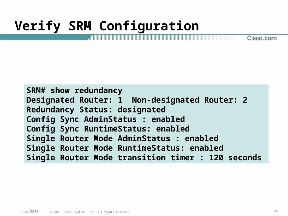
Verify SRM Configuration
• sh redundancy command can be used to verify that SRM is enabled:
• Transition timer is used to ensure routing protocol convergence prior to PFC updates
SRM# show redundancyDesignated Router: 1 Non-designated Router: 2 Redundancy Status: designated Config Sync AdminStatus : enabled Config Sync RuntimeStatus: enabled Single Router Mode AdminStatus : enabled Single Router Mode RuntimeStatus: enabled Single Router Mode transition timer : 120 seconds
262626© 2003, Cisco Systems, Inc. All rights reserved.Jan 2003 262626© 2001, Cisco Systems, Inc. All rights reserved.Presentation_ID