Embed Size (px)
Citation preview

1© 2003, Cisco Systems, Inc. All rights reserved.
CCNA 4 v3.1 Module 5 Frame Relay
Cisco Networking Academy

222© 2003, Cisco Systems, Inc. All rights reserved.
Objectives
• Frame Relay concepts
• Configuring Frame Relay
333© 2003, Cisco Systems, Inc. All rights reserved.
Frame Relay
• Frame Relay is a packet-switched, connection-oriented, WAN service.
• Frame Relay operates at the data link layer of the OSI reference model.
• Frame Relay uses a subset of the high-level data-link control (HDLC) protocol called Link Access Procedure for Frame Relay (LAPF).
444© 2003, Cisco Systems, Inc. All rights reserved.
Frame Relay DTEs and DCEs
• In a Frame Relay topology the routers at the edge of each LAN are the DTEs.
The Frame Relay switch is a DCE device.
• A serial connection, such as a T1 leased line (local loop), will connect the router to a Frame Relay switch of the carrier at the nearest point-of-presence for the carrier.

555© 2003, Cisco Systems, Inc. All rights reserved.
Terminology
• The connection through the Frame Relay network between two DTEs is called a virtual circuit (VC).
• Generally, permanent virtual circuits (PVCs) that have been preconfigured by the carrier are used.
• Virtual circuits may be established dynamically by sending signaling messages to the network. In this case they are called switched virtual circuits (SVCs).
–SVCs are far less common than PVCs
–SVCs are more common with X.25, the predecessor of FR

666© 2003, Cisco Systems, Inc. All rights reserved.
PVCs and DLCIs
• The Frame Relay router connected to the Frame Relay network may have multiple virtual circuits connecting it to various end points.
• The various virtual circuits on a single access line can be distinguished because each VC has its own Data Link Connection Identifier (DLCI).

777© 2003, Cisco Systems, Inc. All rights reserved.
Frame Relay Functions
1. Frame Relay receives a packet from the network layer protocol, such as IP.
2. Frame Relay wraps it with a layer 2 address field which contains the DLCI.
3. The frame is then passed to the physical layer and transmitted on the wire.

888© 2003, Cisco Systems, Inc. All rights reserved.
Frame Relay Operation

999© 2003, Cisco Systems, Inc. All rights reserved.
PVCs and DLCIs
• The Frame Relay router connected to the Frame Relay network may have multiple virtual circuits connecting it to various end points.
• The various virtual circuits on a single access line can be distinguished because each VC has its own Data Link Connection Identifier (DLCI).
• The 10-bit DLCI field of the Frame Relay frame allows VC identifiers 0 through 1023.
The LMI extensions reserve some of these identifiers.
101010© 2003, Cisco Systems, Inc. All rights reserved.
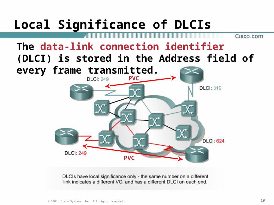
Local Significance of DLCIs
The data-link connection identifier (DLCI) is stored in the Address field of every frame transmitted.
PVC
PVC

111111© 2003, Cisco Systems, Inc. All rights reserved.
Frame Relay Switches
• Frame Relay switches basically route (switch) from one DLCI to another.
Each local serial interface is assigned a local DLCI.
• In order for layer 3 routed protocols to run over Frame Relay interfaces, each interfaces IP address must be mapped to a layer 2 DLCI.
• This mapping of the remote IP address to a local DLCI occurs at the local router’s interface via a ‘frame-relay map’ or through inverse ARP.
-if)#frame-relay map ip 172.31.254.2 201
Local DLCI

121212© 2003, Cisco Systems, Inc. All rights reserved.
Link Management Interface (LMI)
• The purpose of LMI is for DTEs to dynamically acquire information about the status of the network. – Status messages help verify the integrity of logical and
physical links.
– LMI messages are exchanged between the DTE and DCE using reserved DLCIs
• Three types of LMIs are supported by Cisco routers:1. Cisco — The original LMI extensions (Cisco, Nortel and Digital)
2. Ansi — Corresponding to the ANSI standard T1.617 Annex D
3. q933a — Corresponding to the ITU standard Q933 Annex A
• The LMI type must be specified at the Frame Relay interface as the three LMI types are incompatible with one another. – Cisco routers, of course, default to Cisco.The LMI type can be dynamically learned – LMI Autosense
-if)# frame-relay lmi-type [cisco | ansi | q933a]

131313© 2003, Cisco Systems, Inc. All rights reserved.
Inverse ARP and LMI
• LMI status messages combined with Inverse ARP allow a router to associate network layer and data link layer addresses.
• When a router that is connected to a Frame Relay network is started, it sends an LMI status inquiry message to the network.
• The network replies with an LMI status message containing details of every VC configured on the access link.
• If the router needs to map the VC’s DLCIs to network layer addresses, it will send an Inverse ARP message on each VC.
Inverse ARP is enabled by default once you configure the encapsulation type on the serial interface as Frame Relay.
If a static ‘frame-relay map’ is configured then Inverse ARP is disabled on that interface.
config)# int s0/0.102 point-to-point

141414© 2003, Cisco Systems, Inc. All rights reserved.
Frame Relay LMI Types

151515© 2003, Cisco Systems, Inc. All rights reserved.
Stages of Inverse ARP and LMI Operation #1
DLCI 101

161616© 2003, Cisco Systems, Inc. All rights reserved.
Stages of Inverse ARP and LMI Operation #2
DLCI 101
172.16.0.1

171717© 2003, Cisco Systems, Inc. All rights reserved.
Configuring Basic Frame Relay

181818© 2003, Cisco Systems, Inc. All rights reserved.
Configuring a Static Frame Relay Map

191919© 2003, Cisco Systems, Inc. All rights reserved.
Reachability Issues with Routing Updates in NBMA
By default, a Frame Relay network provides nonbroadcast multiaccess (NBMA) connectivity between remote sites.
An NBMA environment is treated like other multiaccess media environments, where all the routers are on the same subnet.
This causes a problem for split-horizon.192.168.1.0/24

202020© 2003, Cisco Systems, Inc. All rights reserved.
Frame Relay and Split-Horizon
• Split-horizon will not accept a routing update about a network that it has sent an update for.– If RTA sends an update for network 192.168.1.0/24 out of
its s0/0 interface then it will not accept an update about 192.168.1.0/24 from RTB, RTC or RTD on that same interface.
• The solution is to either:
1. Use a separate physical interface for each PVC
2. Turn off split-horizon on the interface
3. Configure sub-interfaces

212121© 2003, Cisco Systems, Inc. All rights reserved.
Subinterfaces
• To enable the forwarding of broadcast routing updates in a hub-and-spoke Frame Relay topology, configure the hub router with logically assigned interfaces.
• These interfaces are called subinterfaces.
Subinterfaces can configured as point-to-point or multipoint.
Point-to-point interfaces are all on separate subnets whereas multipoint interfaces are all on the same subnet.
Configuring subinterfaces is much more common because it creates a less complex routing protocol configuration (OSPF)

222222© 2003, Cisco Systems, Inc. All rights reserved.
Frame Relay Subinterfaces

232323© 2003, Cisco Systems, Inc. All rights reserved.
Configuring Point-to-Point Subinterfaces

242424© 2003, Cisco Systems, Inc. All rights reserved.
Verifying Frame Relay
• The show interfaces command displays information regarding the encapsulation and Layer 1 and Layer 2 status. It also displays information about the following:
1. The LMI type
2. The LMI DLCI
3. The Frame Relay (DTE/DCE) type
4. Clockrate on DCE

252525© 2003, Cisco Systems, Inc. All rights reserved.
The show frame-relay lmi Command

262626© 2003, Cisco Systems, Inc. All rights reserved.
The show frame-relay pvc Command

272727© 2003, Cisco Systems, Inc. All rights reserved.
The show frame-relay map Command

282828© 2003, Cisco Systems, Inc. All rights reserved.
Troubleshooting Frame Relay
• Use the debug frame-relay lmi command to determine whether the router and the Frame Relay switch are sending and receiving LMI packets properly.

292929© 2003, Cisco Systems, Inc. All rights reserved.
Frame Relay Congestion Notification
• There are two types of FR congestion notificationForward Explicit Congestion Notification (FECN)
Backward Explicit Congestion Notification (BECN)
• Network DCE devices (switches) change the value of the FECN bit to one on packets traveling in the same direction as the data flow.
This notifies an interface device (DTE) that congestion avoidance procedures should be initiated by the receiving device.
• BECN bits are set in frames that travel the opposite direction of the data flow to inform the transmitting DTE device of network congestion.
• In order for FECN and BECN bits to effect network congestion, the receiving frame relay DTE interfaces must be configured for frame relay traffic shaping

303030© 2003, Cisco Systems, Inc. All rights reserved.
Frame Relay Concepts

313131© 2003, Cisco Systems, Inc. All rights reserved.
Full-Mesh Topology

323232© 2003, Cisco Systems, Inc. All rights reserved.
Frame Relay Mesh