Embed Size (px)
Citation preview

Valid for
ControlSINUMERIK 840D sl/840DE sl
Software VersionNCU system software forSINUMERIK 840D sl/840DE sl 1.3with ShopTurn 7.1
08/2005 Edition
CNC Part 4 (ShopTurn)
SINUMERIK 840D sl
Installation and Startup Manual
Hardware 1
General Conditions 2
Reserved Functions 3
Start-Up 4
PLC Program 5
Signal Description 6
Machine Data 7
Tool Management 8
Additional Functions 9
Customized User Interface 10
Miscellaneous 11
Abbreviations A
References B
Index C

SINUMERIK Documentation
Printing history
Brief details of this edition and previous editions are listed below.
The status of each edition is shown by the code in the “Remarks” column.
Status code in the “Remarks” column:
A New documentation.. . . . . B Unrevised reprint with new Order No.. . . . . C Revised edition with new status. . . . . .
Edition Order No. Remarks03/2001 6FC5 297-6AD70-0BP0 A01/2002 6FC5 297-6AD70-0BP1 C03/2004 6FC5 297-6AD70-0BP2 C08/2005 6FC5 397-5AP10-0BA0 C
TrademarksSIMATIC�, SIMATIC HMI�, SIMATIC NET�, SIROTEC�, SINUMERIK� and SIMODRIVE� are registeredtrademarks of Siemens AG. Other names in this publication might be trademarks whose use by a third partyfor his own purposes may violate the rights of the registered holder.
Further information is available in the Internet under:http://www.siemens.com/motioncontrol
This publication was produced with Interleaf V 7
Siemens AG, 2005.
Other functions not described in this documentation may beexecutable in the control. However, no claim can be made regardingthe availability of these functions when the equipment is first suppliedor in the event of servicing.
We have checked that the contents of this document correspond tothe hardware and software described. Nevertheless, differencesmight exist and we cannot, therefore, guarantee that they arecompletely identical. However, the data in this manual are reviewedregularly and any necessary corrections included in subsequenteditions. Suggestions for improvement are also welcome.
Subject to change without prior notice.
Siemens AktiengesellschaftOrder no. 6FC5 397-5AP10-0BA0Printed in Germany

v Siemens AG, 2005. All rights reservedSINUMERIK 840D sl Installation and Startup Manual CNC Part 4 (ShopTurn) – 08/2005 Edition
Preface
The SINUMERIK documentation is subdivided into 3 parts:
� General documentation
� User documentation
� Manufacturer / Service documentation
More detailed information about other publications concerning SINUMERIK840D sl and publications that apply to all SINUMERIK controls (e.g., UniversalInterface, Measuring Cycles, etc.) can be obtained from your local Siemensbranch office.
A list of documents, updated on a monthly basis, is available on the Internet forthe available languages at:http://www.siemens.com/motioncontrol.Select the menu items ––> “Support” ––> “Technical documentation” ––> “Over-view of documents”.
DOConWeb is the Internet version of DOConCD; you can find this at:http://www.automation.siemens.com/doconweb
This documentation is intended for manufacturers of single-carriage turningmachines using SINUMERIK 840D sl; it provides information needed forconfiguring and commissioning ShopTurn.
If you have any questions, please contact the following hotline:A&D Technical Support Phone: +49 (0) 180 5050-222
Fax: +49 (0) 180 5050-223E-mail: mailto:[email protected]://www.siemens.com/automation/support-request
If you have any queries (suggestions, corrections) in relation to this documenta-tion, please fax or e-mail us:E-Mail: mailto:[email protected]: +49 (0) 9131 98-63315
A fax reply form is provided at the end of this document.
http://www.siemens.com/motioncontrol
SINUMERIK documentation
Target audience
Hotline
Internet address

08/2005
vi Siemens AG, 2005. All rights reserved
SINUMERIK 840D sl Installation and Startup Manual CNC Part 4 (ShopTurn) – 08/2005 Edition
This document provides information about the control system design and theinterfaces of the individual components. It also describes the start-up andinstallation procedure for ShopTurn with SINUMERIK 840D sl.
For detailed information about individual functions, function assignment andperformance data of individual components, please refer to the appropriatedocument for the subject concerned (e.g. manuals, description of functionsetc.).
User-oriented activities such as the creation of parts programs and controloperating procedures are described in details in separate documents.
Further descriptions of tasks to be performed by the machine tool manufacturerare also available for the standard SINUMERIK 840D sl. We may refer to themin this documentation if appropriate.
In addition to the table of contents, we have provided the following informationin the appendix for your assistance:
1. List of abbreviations
2. Index
SINUMERIK 840D sl alarms are listed in
References: /DA/, Diagnostics Guide
For further useful information on start-up and troubleshooting, please refer to
References: /FB/, D1, “Diagnostics Tools”
The following symbols with special significance are used in the documentation:
Note
This symbol always appears in this documentation where further, explanatoryinformation is provided.
This manual contains information which you should observe in order to ensureyour own personal safety, as well to avoid material damage. Notes relating toyour safety are highlighted in the manual by means of a warning triangle; nowarning triangle appears in conjunction with notes relating to material damage.The warnings appear in descending order of risk as given below.
!Danger
This warning indicates that death or severe personal injury will result if theappropriate precautions are not taken.
Standard version
Findinginformation
Notes
Safety information
Preface

08/2005
vii Siemens AG, 2005. All rights reservedSINUMERIK 840D sl Installation and Startup Manual CNC Part 4 (ShopTurn) – 08/2005 Edition
!Warning
This warning indicates that death or severe personal injury may result if theproper precautions are not taken.
!Caution
This warning (with the warning triangle symbol) means that minor physicalinjury may occur if the appropriate precautions are not taken.
Caution
This warning (without the warning triangle) means that material damage mayresult if proper precautions are not taken.
Notice
This warning indicates that an undesirable result or state may result if theappropriate precautions are not taken.
Start-up and operation of the device / equipment/ system in question must onlybe performed using this documentation. Commissioning and operation of a de-vice/system may only be performed by qualified personnel. Qualified person-nel as referred to in the safety instructions in this documentation are personsauthorized to start up, ground, and label devices, systems, and circuits in accor-dance with the relevant safety standards.
Please note the following:
!Warning
The equipment may only be used for single-purpose applications explicitlydescribed in the catalog and in the technical description; it may only be used inconjunction with third-party devices and components recommended bySiemens. To ensure trouble-free and safe operation of the product, it must betransported, stored and installed as intended and maintained and operated withcare.
Qualifiedpersonnel
Intended use
Preface

08/2005
viii Siemens AG, 2005. All rights reserved
SINUMERIK 840D sl Installation and Startup Manual CNC Part 4 (ShopTurn) – 08/2005 Edition
In this manual, the units of the parameters are always indicated as metric va-lues. The equivalent imperial units are shown in the table below.
Metric Inch
mm in
mm/tooth in/tooth
mm/min in/min
mm/rev in/rev
m/min ft/min
Unit ofmeasurement
Preface

ix Siemens AG, 2005. All rights reservedSINUMERIK 840D sl Installation and Startup Manual CNC Part 4 (ShopTurn) – 08/2005 Edition
Contents
1 Hardware 1-13. . . . . . . . . . . . . . . . . . . . . . . . . . . . . . . . . . . . . . . . . . . . . . . . . . . . . . . . .
2 General Conditions 2-15. . . . . . . . . . . . . . . . . . . . . . . . . . . . . . . . . . . . . . . . . . . . . . . .
3 Reserved Functions 3-17. . . . . . . . . . . . . . . . . . . . . . . . . . . . . . . . . . . . . . . . . . . . . . .
4 Start-Up 4-19. . . . . . . . . . . . . . . . . . . . . . . . . . . . . . . . . . . . . . . . . . . . . . . . . . . . . . . . . . .
4.1 Requirements 4-19. . . . . . . . . . . . . . . . . . . . . . . . . . . . . . . . . . . . . . . . . . . . .
4.2 Initial start-up 4-21. . . . . . . . . . . . . . . . . . . . . . . . . . . . . . . . . . . . . . . . . . . . . 4.2.1 Sequence 4-21. . . . . . . . . . . . . . . . . . . . . . . . . . . . . . . . . . . . . . . . . . . . . . . . 4.2.2 Installation of ShopTurn on NCU (HMI embedded) 4-23. . . . . . . . . . . . . 4.2.3 Installing ShopTurn on the PCU 50.3 4-23. . . . . . . . . . . . . . . . . . . . . . . . . 4.2.4 PLC start-up 4-24. . . . . . . . . . . . . . . . . . . . . . . . . . . . . . . . . . . . . . . . . . . . . . 4.2.5 NCK start-up 4-25. . . . . . . . . . . . . . . . . . . . . . . . . . . . . . . . . . . . . . . . . . . . . . 4.2.6 Display machine data 4-27. . . . . . . . . . . . . . . . . . . . . . . . . . . . . . . . . . . . . . 4.2.7 Acceptance report 4-27. . . . . . . . . . . . . . . . . . . . . . . . . . . . . . . . . . . . . . . . .
5 PLC Program 5-29. . . . . . . . . . . . . . . . . . . . . . . . . . . . . . . . . . . . . . . . . . . . . . . . . . . . .
5.1 Structure of the PLC program 5-29. . . . . . . . . . . . . . . . . . . . . . . . . . . . . . .
5.2 Example source files 5-29. . . . . . . . . . . . . . . . . . . . . . . . . . . . . . . . . . . . . . .
5.3 Standard interface signals for / from ShopTurn 5-31. . . . . . . . . . . . . . . . .
6 Signal Description 6-33. . . . . . . . . . . . . . . . . . . . . . . . . . . . . . . . . . . . . . . . . . . . . . . . .
6.1 HMI interface DB19 6-33. . . . . . . . . . . . . . . . . . . . . . . . . . . . . . . . . . . . . . . .
6.2 HMI interface DB21 6-37. . . . . . . . . . . . . . . . . . . . . . . . . . . . . . . . . . . . . . . .
6.3 Overview of earlier ShopTurn interface 6-38. . . . . . . . . . . . . . . . . . . . . . . 6.3.1 Signals to ShopTurn (input signals) 6-38. . . . . . . . . . . . . . . . . . . . . . . . . . . 6.3.2 Signals from ShopTurn (output signals) 6-40. . . . . . . . . . . . . . . . . . . . . . .
7 Machine Data 7-43. . . . . . . . . . . . . . . . . . . . . . . . . . . . . . . . . . . . . . . . . . . . . . . . . . . . . .
7.1 NCK machine data for ShopTurn 7-43. . . . . . . . . . . . . . . . . . . . . . . . . . . . .
7.2 Display machine data for ShopTurn 7-45. . . . . . . . . . . . . . . . . . . . . . . . . . 7.2.1 Overview of display machine data 7-45. . . . . . . . . . . . . . . . . . . . . . . . . . . . 7.2.2 Description of display machine data 7-49. . . . . . . . . . . . . . . . . . . . . . . . . .
8 Tool Management 8-77. . . . . . . . . . . . . . . . . . . . . . . . . . . . . . . . . . . . . . . . . . . . . . . . .
8.1 Overview of functions 8-77. . . . . . . . . . . . . . . . . . . . . . . . . . . . . . . . . . . . . .
8.2 Start-up sequence 8-79. . . . . . . . . . . . . . . . . . . . . . . . . . . . . . . . . . . . . . . . .
8.3 Start-up in NCK 8-80. . . . . . . . . . . . . . . . . . . . . . . . . . . . . . . . . . . . . . . . . . . 8.3.1 Enter the NC machine data 8-81. . . . . . . . . . . . . . . . . . . . . . . . . . . . . . . . . 8.3.2 Description of NCK machine data 8-83. . . . . . . . . . . . . . . . . . . . . . . . . . . . 8.3.3 Creating and loading the configuration file 8-89. . . . . . . . . . . . . . . . . . . . .
8.4 Start-up in the PLC 8-95. . . . . . . . . . . . . . . . . . . . . . . . . . . . . . . . . . . . . . . .

08/2005
x Siemens AG, 2005. All rights reserved
SINUMERIK 840D sl Installation and Startup Manual CNC Part 4 (ShopTurn) – 08/2005 Edition
8.4.1 Example for FC 100 and FB 110 8-97. . . . . . . . . . . . . . . . . . . . . . . . . . . . . 8.4.2 Signal description 8-98. . . . . . . . . . . . . . . . . . . . . . . . . . . . . . . . . . . . . . . . . .
8.5 Display machine data 8-107. . . . . . . . . . . . . . . . . . . . . . . . . . . . . . . . . . . . . .
8.6 Enable spindle and coolant 8-108. . . . . . . . . . . . . . . . . . . . . . . . . . . . . . . . . .
8.7 Moving the turret manually 8-109. . . . . . . . . . . . . . . . . . . . . . . . . . . . . . . . . .
8.8 Configuring the operator interface 8-112. . . . . . . . . . . . . . . . . . . . . . . . . . . . 8.8.1 Integrating additional list 8-112. . . . . . . . . . . . . . . . . . . . . . . . . . . . . . . . . . . . 8.8.2 Configuring lists 8-113. . . . . . . . . . . . . . . . . . . . . . . . . . . . . . . . . . . . . . . . . . . 8.8.3 Creating the configuration file 8-114. . . . . . . . . . . . . . . . . . . . . . . . . . . . . . . . 8.8.4 Define texts 8-120. . . . . . . . . . . . . . . . . . . . . . . . . . . . . . . . . . . . . . . . . . . . . . .
8.9 Importing tool data 8-122. . . . . . . . . . . . . . . . . . . . . . . . . . . . . . . . . . . . . . . . .
9 Additional Functions 9-127. . . . . . . . . . . . . . . . . . . . . . . . . . . . . . . . . . . . . . . . . . . . . .
9.1 Measuring cycle 9-127. . . . . . . . . . . . . . . . . . . . . . . . . . . . . . . . . . . . . . . . . . . 9.1.1 Brief description 9-127. . . . . . . . . . . . . . . . . . . . . . . . . . . . . . . . . . . . . . . . . . . 9.1.2 Display machine data for measuring cycle 9-128. . . . . . . . . . . . . . . . . . . . .
9.2 Network link 9-130. . . . . . . . . . . . . . . . . . . . . . . . . . . . . . . . . . . . . . . . . . . . . . .
9.3 Cylinder surface transformation, end face machining 9-131. . . . . . . . . . . 9.3.1 General information 9-131. . . . . . . . . . . . . . . . . . . . . . . . . . . . . . . . . . . . . . . . 9.3.2 Example: X axis and Z axis, main spindle and tool spindle 9-132. . . . . . . 9.3.3 Example: X axis and Z axis, main spindle and tool spindle, Y axis 9-1349.3.4 Example: X axis and Z axis, main spindle, tool spindle and
counter-spindle 9-136. . . . . . . . . . . . . . . . . . . . . . . . . . . . . . . . . . . . . . . . . . . . 9.3.5 Example: X axis and Z axis, main spindle, tool spindle, and
counter-spindle, Y axis 9-138. . . . . . . . . . . . . . . . . . . . . . . . . . . . . . . . . . . . .
9.4 Inclined Y axis 9-140. . . . . . . . . . . . . . . . . . . . . . . . . . . . . . . . . . . . . . . . . . . . .
9.5 Measuring cycle support in the G code editor 9-143. . . . . . . . . . . . . . . . . .
9.6 Counter-spindle 9-145. . . . . . . . . . . . . . . . . . . . . . . . . . . . . . . . . . . . . . . . . . .
10 Customized User Interface 10-149. . . . . . . . . . . . . . . . . . . . . . . . . . . . . . . . . . . . . . . . .
10.1 Configuring the custom boot screen 10-149. . . . . . . . . . . . . . . . . . . . . . . . . .
10.2 Configuring the custom screen 10-150. . . . . . . . . . . . . . . . . . . . . . . . . . . . . . 10.2.1 Transferring cycles to the machining plan 10-154. . . . . . . . . . . . . . . . . . . . . 10.2.2 Linking cycles into the machining plan 10-155. . . . . . . . . . . . . . . . . . . . . . . . 10.2.3 Integrating measuring cycles 10-156. . . . . . . . . . . . . . . . . . . . . . . . . . . . . . . .
10.3 ShopTurn Open (PCU 50.3) 10-157. . . . . . . . . . . . . . . . . . . . . . . . . . . . . . . . . 10.3.1 Basic menu bar 10-157. . . . . . . . . . . . . . . . . . . . . . . . . . . . . . . . . . . . . . . . . . . .
10.4 Operator interface for ShopTurn on the NCU (HMI Embedded) 10-158. . .
10.5 User status display 10-159. . . . . . . . . . . . . . . . . . . . . . . . . . . . . . . . . . . . . . . . . 10.5.1 Configuring the user status display 10-160. . . . . . . . . . . . . . . . . . . . . . . . . . .
10.6 OP hotkeys, PLC keys 10-162. . . . . . . . . . . . . . . . . . . . . . . . . . . . . . . . . . . . .
11 Miscellaneous 11-163. . . . . . . . . . . . . . . . . . . . . . . . . . . . . . . . . . . . . . . . . . . . . . . . . . . . .
11.1 Machine data for protection levels 11-163. . . . . . . . . . . . . . . . . . . . . . . . . . . .
11.2 Machine manufacturer cycle 11-165. . . . . . . . . . . . . . . . . . . . . . . . . . . . . . . . .
Contents

08/2005
xi Siemens AG, 2005. All rights reservedSINUMERIK 840D sl Installation and Startup Manual CNC Part 4 (ShopTurn) – 08/2005 Edition
11.3 Spindle control 11-166. . . . . . . . . . . . . . . . . . . . . . . . . . . . . . . . . . . . . . . . . . . .
11.4 ISO dialects 11-169. . . . . . . . . . . . . . . . . . . . . . . . . . . . . . . . . . . . . . . . . . . . . . .
11.5 Automatically generated programs 11-170. . . . . . . . . . . . . . . . . . . . . . . . . . .
11.6 Manual machine 11-171. . . . . . . . . . . . . . . . . . . . . . . . . . . . . . . . . . . . . . . . . . .
11.7 Action log 11-173. . . . . . . . . . . . . . . . . . . . . . . . . . . . . . . . . . . . . . . . . . . . . . . . .
11.8 Version display 11-174. . . . . . . . . . . . . . . . . . . . . . . . . . . . . . . . . . . . . . . . . . . .
A Abbreviations A-175. . . . . . . . . . . . . . . . . . . . . . . . . . . . . . . . . . . . . . . . . . . . . . . . . . . . .
B References B-177. . . . . . . . . . . . . . . . . . . . . . . . . . . . . . . . . . . . . . . . . . . . . . . . . . . . . . . .
C Index Index-179. . . . . . . . . . . . . . . . . . . . . . . . . . . . . . . . . . . . . . . . . . . . . . . . . . . . . . . . . . . . .
Contents

08/2005
xii Siemens AG, 2005. All rights reserved
SINUMERIK 840D sl Installation and Startup Manual CNC Part 4 (ShopTurn) – 08/2005 Edition
Contents
Notes

1-13 Siemens AG, 2005. All rights reservedSINUMERIK 840D sl Installation and Startup Manual CNC Part 4 (ShopTurn) – 08/2005 Edition
Hardware
The hardware configuration for ShopTurn is as standard for SINUMERIK840D sl.
References: /IDS/, Commissioning Manual CNC Part 1 (NCK, PLC,Drive), SINUMERIK 810D sl;
/GDS/, Device Manual NCUSINUMERIK 840D sl,
Table 1-1 Basic components
Basic components Order number Comment
TCU 6FC5312-0DA00-0AA0
NCU 710.1 6FC5371-0AA00-0AA0 CNC: 1 MB; PLC: 128 KB
NCU 720.1 6FC5372-0AA00-0AA0 CNC: 2 MB; PLC: 128 KB
Table 1-2 Operator components
Operator control components Order number Comment
OP010 operator panel 6FC5203-0AF00-0AA0
OP010C operator panel 6FC5203-0AF01-0AA0
OP010S operator panel 6FC5203-0AF04-0AA0
OP012 operator panel 6FC5203-0AF02-0AA0
OP015 operator panel 6FC5203-0AF03-0AA0
PCU 50.3 – C 6FC5210-0DF31-2AA0 1.5 GHz, 512 MB, Windows XP
PCU 50.3 – P 6FC5210-0DF33-2AA0 2.0 GHz, 1024 MB, Windows XP
MCP 310 6FC5203-0AF23-1AA0
CNC full keyboard KB 310C 6FC5203-0AF21-0AA0
MCP 483 6FC5203-0AF22-1AA1
MCP 483C 6FC5203-0AF22-0AA0
Key cap forMCP
6FC5148-0AF12-0AA06FC5148-0AF21-0AA0
ColoredClear
�
System structure
1

08/2005
1-14 Siemens AG, 2005. All rights reserved
SINUMERIK 840D sl Installation and Startup Manual CNC Part 4 (ShopTurn) – 08/2005 Edition
1 Hardware
Notes

2-15 Siemens AG, 2005. All rights reservedSINUMERIK 840D sl Installation and Startup Manual CNC Part 4 (ShopTurn) – 08/2005 Edition
General Conditions
When using ShopTurn please observe the following general conditions:
� ShopTurn only runs in channel 1, mode group 1.
� ShopTurn has been designed for use with universal turning machines withfour axes (X, Z, Y, and auxiliary axis for counterspindle) and 3 spindles(main, tool, and counterspindle).
� ShopTurn only runs with tool management.
� If you want to use rotating tools, you need the software option “cylinder sur-face transformation” (Tracyl) and “end face machining” (Transmit).Order number 6FC5 800-0AM27-0YB0
� If you want to use a counterspindle on your machine, you need the softwareoptions “travel to fixed stop” (order no. 6FC5 800-0AM01-0YB0) and “syn-chronous spindle” (order no. 6FC5 800-0AM14-0YB0).
� With ShopTurn Open you must not change the position of the following soft-keys in the basic menu bar; i.e. in the REGIE.INI file these functions mustalways have been assigned a specific task.Task 0 (horizontal softkey 1): Operating area – Machine Task 1 (horizontal softkey 2): Operating area – Program manager Task 2 (horizontal softkey 3): Operating area – Program Task 4 (horizontal softkey 5): Operating area – Tools / Zero offsets
� With ShopTurn it is possible via TCU to use several operator panels.
� The HMI and Windows screen savers must not be used together.References: /IAM/, Commissioning Manual CNC Part 2 (HMI),
SINUMERIK, 840D sl/840D/840Di/810D,/IM2/ Commissioning HMI Embedded (sl)/IM4/ Commissioning HMI Advanced
�
2

08/2005
2-16 Siemens AG, 2005. All rights reserved
SINUMERIK 840D sl Installation and Startup Manual CNC Part 4 (ShopTurn) – 08/2005 Edition
2 General Conditions
Notes

3-17 Siemens AG, 2005. All rights reservedSINUMERIK 840D sl Installation and Startup Manual CNC Part 4 (ShopTurn) – 08/2005 Edition
Reserved Functions
The following functions are utilized by ShopTurn and must not be assigned forother purposes.
The system cycle PROG_EVENT.SPF is used by the standard cycles and byShopTurn.If you want to use the cycle PROG_EVENT.SPF for user functions too, it is ne-cessary to implement these user functions in the cycles CYCPE_US.SPF andCYCPE1US.SPF. Save these cycles in the directory for user cycles or manufac-turer cycles.
�
PROG_EVENT
3

08/2005
3-18 Siemens AG, 2005. All rights reserved
SINUMERIK 840D sl Installation and Startup Manual CNC Part 4 (ShopTurn) – 08/2005 Edition
3 Reserved Functions
Notes

4-19 Siemens AG, 2005. All rights reservedSINUMERIK 840D sl Installation and Startup Manual CNC Part 4 (ShopTurn) – 08/2005 Edition
Start-Up
4.1 Requirements
For data transfer you require:
� Hardware
– Programming device with Windows XP or a PC with Ethernet
– or a memory stick (order number: 6ES7 648-0DC20-0AA0)
� Software
– SIMATIC Step 7, version 5.3 or later, SP2 (see SIMATIC catalog for or-der number)
� ShopTurn on NCU (HMI embedded)
With the ShopTurn variant on NCU (HMI embedded) the software is alreadypre-installed on the CompactFlash Card.
� ShopTurn for PCU 50.3
The necessary software is located on the ShopTurn CD-ROM. The procedurefor installing the software on PCU and NCK/PLC is described in the followingsections.
Note
The contents of the ShopTurn CD-ROM are listed in the files SIEMENSD.RTF (German) and SIEMENSE.RTF (English).A compatibility list is provided in file COMPAT.XLS.
Data transfer
ShopTurn-software
4

08/20054.1 Requirements
4-20 Siemens AG, 2005. All rights reserved
SINUMERIK 840D sl Installation and Startup Manual CNC Part 4 (ShopTurn) – 08/2005 Edition
The complete pre-installed software is located on the CompactFlash Card:
– Drive software (Sinamics)
– PLC software
– NCK software
– ShopTurn
– Cycles
The software is provided in 6 languages (German, English, French, Italian,Spanish, and Chinese).
The CD contains the software in 6 languages (German, English, French, Italian,Spanish, and Chinese).
ShopTurn on NCU(HMI embedded)
ShopTurn for PCU 50.3
4 Start-Up

08/20054.2 Initial start-up
4-21 Siemens AG, 2005. All rights reservedSINUMERIK 840D sl Installation and Startup Manual CNC Part 4 (ShopTurn) – 08/2005 Edition
4.2 Initial start-up
4.2.1 Sequence
Before you begin start-up please read the general conditions and reservedfunctions.
For installation and start-up proceed as follows:
� For installation of ShopTurn on PCU from CD (only for ShopTurn onPCU 50.3).For ShopTurn on NCU (HMI embedded) the ShopTurn software is alreadypre-installed.
� PLC installation and start-up
� NCK start-up
� Install additional functions (optional)
� Adapt display machine data
� Customize the operator interface (optional)
� Run a test using the acceptance certificate
You can start up tool management either together with NCK and PLC start-up orafterwards. If tool management is already set up on the machine you only needto adapt the display machine data for tool management; (see Section 8.2“Start-up sequence”).
For an exact description of the start-up procedure please refer to the followingdocumentation:
References: /IDS/, Commissioning Manual CNC Part 1 (NCK, PLC, Drive), SINUMERIK 840D sl,/IAM/, Commissioning Manual CNC Part 2 (HMI), SINUMERIK 840D sl/840D/840Di/810D
IM2 Commissioning HMI Embedded (sl)IM4 Commissioning HMI Advanced
4 Start-Up
08/20054.2 Initial start-up
4-22 Siemens AG, 2005. All rights reserved
SINUMERIK 840D sl Installation and Startup Manual CNC Part 4 (ShopTurn) – 08/2005 Edition
Configure the PLC Load the basic program
Configure the drives
Configure the NCK machine
Load the PLC user project
NCK functions
General machine data
Cycles GUDs, macros
Channel-specificmachine data
Axis machine data
Display machine data
– – – – – – – – – – – – – – – – – – – – – – – – – – – – – – – – – – – – – – – – – – – – – – – – – –
1
2
NCU:HMI Embedded/ShopMill/ShopTurn
PCU 50.3:HMI Advanced/ShopMill/ShopTurn
– – – – – – – – – – – – – – – – – – – – – – – – – – – – – – – – – – – – – – – – – – – – – – – – –
Fig. 4-1 General sequence of initial star-up
(1) The first step in the start-up sequence is to configure the control system, i.e.to set up commmunication between all involved components. PLC, drive, andNCK are put into operation.References: /IDS/, Commissioning Manual CNC Part 1 (NCK, PLC,
Drive), SINUMERIK 840D sl,
(2) The second step is to initialize the various functions; this involves severalruns. The start-up sequence for these functions is described in the followingsections.
General sequenceof initial start-up
4 Start-Up

08/20054.2 Initial start-up
4-23 Siemens AG, 2005. All rights reservedSINUMERIK 840D sl Installation and Startup Manual CNC Part 4 (ShopTurn) – 08/2005 Edition
4.2.2 Installation of ShopTurn on NCU (HMI embedded)
For the purposes of operating ShopTurn on NCU (HMI embedded) the wholesoftware is pre-installed on the CompactFlash Card. Just a few adaptations ofthe NCK and PLC are needed.
Note
ShopTurn uses the alarm texts and PLC messages of the CNC ISO userinterface. For detailed information on this subject and on installing the softwareplease refer to the following documentation:References: /IAM/, Commissioning Manual CNC Part 2 (HMI),
SINUMERIK, 840D sl/840D/840Di/810DIM2 Commissioning HMI Embedded (sl)
4.2.3 Installing ShopTurn on the PCU 50.3
The HMI Advanced software must be installed on the PCU 50.3 before youinstall ShopTurn.
You can install ShopTurn on the PCU 50 in one of three different ways:
� Installation via a network link
� Installation from data media (e.g. CD)
� Installation Via USB interface
Windows XP is required.
Note
ShopTurn uses the alarm texts and PLC messages of the CNC ISO userinterface. For detailed information on this subject and on installing the softwareplease refer to the following documentation:References: /IAM/, Commissioning Manual CNC Part 2 (HMI),
SINUMERIK, 840D sl/840D/840Di/810DIM4 Commissioning HMI Advanced
4 Start-Up

08/20054.2 Initial start-up
4-24 Siemens AG, 2005. All rights reserved
SINUMERIK 840D sl Installation and Startup Manual CNC Part 4 (ShopTurn) – 08/2005 Edition
4.2.4 PLC start-up
To start up the PLC you must first create and then load a PLC user project.
To start up the PLC proceed as follows:
Load the basic PLC program
If tool management has not yet been set up implement call FC8 and create the PLC data(DB4) (see Section 8.4 “PLC start-up”). For example compile a source file:TM_REV_GR.AWL or TM_REV_UK.AWL(data transfer for machine with turret). The example file is located on the Toolbox insub-directory 8x0d under\ShopMill_Turn.
Download PLC user project to PLC
Fig. 4-2 PLC installation and start-up
4 Start-Up

08/20054.2 Initial start-up
4-25 Siemens AG, 2005. All rights reservedSINUMERIK 840D sl Installation and Startup Manual CNC Part 4 (ShopTurn) – 08/2005 Edition
4.2.5 NCK start-up
NCK start-up comprises the following points:
� Set up axes and spindle(s)
� Load ShopTurn machine data, definitions, and cycles
� Set up tool management
You only need to set up the axes and spindles if you have not yet done so onthe machine. When setting up the axes and spindles please observe the gen-eral conditions; (see Chapter 2 “General conditions”).
Similarly, you only need to set up tool management in the NCK if this does notyet exist.
Note: Example files are located in the directories CYCLES\SC\PROG\TEMPLATES_DEU and CYCLES\SC\PROG\TEMPLATES_ENG.
If axes and spindles have not yet beenset up:
Adapt the standard MD to the axes andspindles of the machine.
Check the MDs in the mask “Machine data” and if necessary modifythe axis setting data; (see Section 7.1“NC machine data for ShopTurn”).
NCK reset
1
Fig. 4-3 NC SINUMERIK 840D sl installation and start-up
SINUMERIK 840D sl
4 Start-Up

08/20054.2 Initial start-up
4-26 Siemens AG, 2005. All rights reserved
SINUMERIK 840D sl Installation and Startup Manual CNC Part 4 (ShopTurn) – 08/2005 Edition
Load the definitionsST_DEF.ARC from the PCU50.3 archive.
Load the definitions DEFINES.ARCfrom STANDARDZYKLEN.
PCU 50.3ShopTurn on NCU
Load the cycles CYCLES.ARC fromSTANDARDZYKLEN.
Load the cyclesST_CYC.ARC from thePCU 50.3 archive.
Load the filesSMAC_xx.DEF (xx = SC,ST) and GUD7_xx.DEF (xx= SC, JS, ST) by pressingthe softkey “Load”.
1
Activate the files SMAC.DEFand GUDx.DEF (x = 5, 6, 7) by pressing the softkey“Activate”.
Load these cycles bypressing the softkey “Load”.Note: The cycles arelocated in the directoriesSTANDARDZYKLEN and HERSTELLERZYKLEN.
PCU 50.3: LoadST_CUST.SPF by pressingthe softkey “Load”
If necessary adapt themachine manufacturer cycleST_CUST.SPF from the CD;(see Section 11.2 “Machinemanufacturer cycle”) andtransfer from the directoryCYCLES/SC/HERSTELLERZYKLEN.Note: After transfer, the cycleis located in the directoryANWENDERZYKLEN.
2
Activate the files SMAC_SC.DEF,SMAC_ST.DEF, GUDx.DEF (x = 5, 6,7) and GUD7x(x=_JS, _MC, _SC,_ST).DEF by pressing the softkey“Activate”.
Load the definitionsST_DEF_E.ARC fromSCHRITTKETTENZYKLEN.
Load the definitions DEFINES.ARCfrom MESSZYKLEN.
Via operating area “Services” directory /ZYKLENABLAGE, loadthe definitions and cycles from fromthe sub-directories:
Load the cycles ST_CYC_E.ARC from SCHRITTKETTENZYKLEN.
Load the cycles M_CYCLES.ARCfrom MESSZYKLEN.
Load CYCCUST_ST.ARC from STANDARDZYKLEN.
Load the cycles JOG_MEAS.ARC fromMESSZYKLEN/JOG_MEAS.
Fig. 4-4 NCK SINUMERIK 840D sl installation and start-up
4 Start-Up

08/20054.2 Initial start-up
4-27 Siemens AG, 2005. All rights reservedSINUMERIK 840D sl Installation and Startup Manual CNC Part 4 (ShopTurn) – 08/2005 Edition
NCK reset
If tool management has not yet been setup:
create and load the configuration file fortool management; (see Subsection 8.3.3“Create and load the configuration file”).
For example, transfer data from thedirectory \ShopMill_Turn of theToolbox.
2
Fig. 4-5 NCK SINUMERIK 840D sl installation and start-up
4.2.6 Display machine data
Once you have completed installation of ShopTurn on the PCU and start-up ofNCK and PLC you must adapt the display machine data. The display machine data are listed in Section 7.2 “Display machine data forShopTurn”.
4.2.7 Acceptance report
The acceptance report can be used to test the installed ShopTurn functionsonce the ShopTurn installation and start-up have been completed.The acceptance report is included on the ShopTurn CD-ROM.
�
4 Start-Up

08/20054.2 Initial start-up
4-28 Siemens AG, 2005. All rights reserved
SINUMERIK 840D sl Installation and Startup Manual CNC Part 4 (ShopTurn) – 08/2005 Edition
4 Start-Up
Notes

5-29 Siemens AG, 2005. All rights reservedSINUMERIK 840D sl Installation and Startup Manual CNC Part 4 (ShopTurn) – 08/2005 Edition
PLC Program
5.1 Structure of the PLC program
In the OBs 1, 40, and 100 the tool management and basic PLC program (FB 1,FC 2, ...) must be activated.
For a description of the functional blocks and the basic PLC program pleaserefer to:
References: /FB1/, Description of functions, basic machine, P3, “Basic PLC program”
5.2 Example source files
ShopTurn includes a variety of source files for sample blocks. You can adaptand compile these source files.Or you can use your own blocks.
Table 5-1 Example source files
Source Mnemonics Note Block Comments
TM_REV_GR.AWL
German The indicatedblock numbers are program-med in abso-lute terms.
FC 100
FB 110
DB 110
Sample block for config-uring tool management The block is called inOB100.
Sample block for datatransfer of tool manage-ment. The block iscalled in OB1.Instance data block forFB 110
TM_REV_UK.AWL
English like TM_REV_GR.AWL
5

08/20055.2 Example source files
5-30 Siemens AG, 2005. All rights reserved
SINUMERIK 840D sl Installation and Startup Manual CNC Part 4 (ShopTurn) – 08/2005 Edition
Table 5-1 Example source files
Source CommentsBlockNoteMnemonics
TM_REV_M_GR.AWL
German The block des-ignation issymbolic.For example,the followingblock numberscan be as-signed.
TM_REV_M
DB_TM_REV_M
FB4_INST_DB
FC55,Data typeFC55
DB 55Data type DB55
DB56Data type FB4
Sample block for track-ing the turret position.
Data block
Instance data blockfor FB4
TM_REV_M_UK.AWL
English like TM_REV_M_GR.AWL
The sample blocks are located on the Toolbox under \ShopMill_Turn.
5 PLC Program

08/20055.3 Standard interface signals for / from ShopTurn
5-31 Siemens AG, 2005. All rights reservedSINUMERIK 840D sl Installation and Startup Manual CNC Part 4 (ShopTurn) – 08/2005 Edition
5.3 Standard interface signals for / from ShopTurn
The following table lists the standard interface signals that are affected by theShopTurn interface (DB19).
Table 5-2 Standard interface signals for / from ShopTurn
Byte Designation
DB19 Signals from operator panel (HMI–––>PLC)
DBB21 Active MMC operating areasee Section 6.1“HMI interface DB19”
DBX20 Bit6 Simulation activesee Section 6.1 “HMI interface DB19”
DBW24 Current screen number in ShopTurnsee Section 6.1 “HMI interface DB19”
DB21 Signals to NCK channel (PLC–––>NCK)
DBX7.5 Deactivate global start lock see Section 6.2 “HMI interface DB21”
Note
� Feed disable must not be activated in the PLC user program while thespindle is stationary because with “Hole thread cutting with positioning oncircle” the axes are positioned on the next hole as per the federate evenwith a stationary spindle.
�
5 PLC Program

08/20055.3 Standard interface signals for / from ShopTurn
5-32 Siemens AG, 2005. All rights reserved
SINUMERIK 840D sl Installation and Startup Manual CNC Part 4 (ShopTurn) – 08/2005 Edition
5 PLC Program
Notes
6-33 Siemens AG, 2005. All rights reservedSINUMERIK 840D sl Installation and Startup Manual CNC Part 4 (ShopTurn) – 08/2005 Edition
Signal Description
6.1 HMI interface DB19
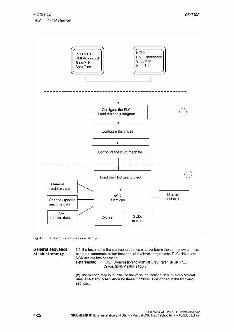
DB19 E_SimActivDBX20.6 Simulation activeData block Signal(s) from ShopTurnEdge evaluation: No Signal(s) updated: cyclic Signal(s) valid from software version:
ShopTurn 6.1Significance of signal 0: Exit simulation
1: Start simulation
DB19 E_AcitivWADBB21 Active MMC operating areaData block Signal(s) from ShopTurnEdge evaluation: No Signal(s) updated: cyclic Signal(s) valid from software version:
ShopTurn 7.1Significance of signal OPEN (HMI Advanced)
SK number (as indicated in the schedule (Task+1))Classic (HMI Embedded)201: ST machine202: ST directory203: ST program204 ST alarms / messages205 ST tool
6
08/20056.1 HMI interface DB19
6-34 Siemens AG, 2005. All rights reserved
SINUMERIK 840D sl Installation and Startup Manual CNC Part 4 (ShopTurn) – 08/2005 Edition
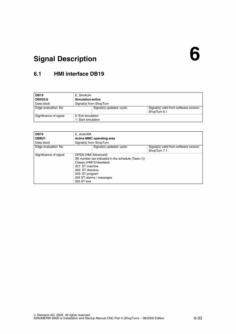
DB19 Mask numberDBW24 Current screen number in ShopTurnData block Signal(s) from ShopTurnEdge evaluation: No Signal(s) updated: cyclic Signal(s) valid from software version:
ShopTurn 7.1Significance of signal The signal indicates the screen number of the current ShopTurn screen.
The following screen numbers can be issued:No. ShopTurn screenOperating mode, machine / manual (without option “Manual machine”)19 Basic screen2 T,S,M...21 Set zero offset *30 Zero-point work piece31 Zero-point work piece – user mask *34 Zero-point workpiece – user mask *35 Zero-point workpiece – user mask *36 Zero-point workpiece – user mask *37 Zero-point workpiece – user mask *38 Zero-point workpiece – user mask *40 Zero-point workpiece – user mask *5 Zero-point workpiece – measure edge Z50 Measure tool 51 Measure tool – manual – X / user mask *52 Measure tool – manual – Z / user mask *53 Measure tool – zoom-in * / user mask *54 Measure tool – user mask *55 Measure tool – user mask *56 Measure tool – adjustment probe * / user mask *57 Measure tool – user mask *58 Measure tool – automatic Z *59 Measure tool – automatic X *4 Position18 Facing tool *80 Stock removal *81 Cycle start mask (stock removal / facing) – Confirm with OK *90 User mask – tail stock *91 User mask – tail stock – Confirm with OK *1 ShopTurn settings
Operating mode – machine / hand(with option “Manual machine”):19 Basic screen1 ShopTurn settings 21 Set zero offset *50 Measure tool 51 Measure tool – manual – X / user mask *52 Measure tool – manual – Z / user mask *53 Measure tool – zoom-in * / user mask *54 Measure tool – user mask *55 Measure tool – user mask *56 Measure tool – adjustment probe * / user mask *57 Measure tool – user mask *58 Measure tool – automatic Z *59 Measure tool – automatic X *81 Cycle start mask (drilling / turning / milling) – Confirm with OK *90 User mask – tail stock *91 User mask – tail stock – Confirm with OK *1300 Straight
6 Signal Description

08/20056.1 HMI interface DB19
6-35 Siemens AG, 2005. All rights reservedSINUMERIK 840D sl Installation and Startup Manual CNC Part 4 (ShopTurn) – 08/2005 Edition
DB19 Mask numberDBW24 Current screen number in ShopTurnData block Signal(s) from ShopTurnSignificance of signal 1400 Drilling
1410 Drilling – center1420 Drilling – thread center1433 Drilling – centering1434 Drilling – drilling 1435 Drilling – rubbing1440 Drilling – deep-drilling1453 Drilling – thread-cutting 1454 Drilling – thread-milling 1500 Turning1513 Turning – stock removal 11514 Turning – stock removal 21515 Turning – stock removal 31523 Turning – grooving 11524 Turning – grooving 21525 Turning – grooving 31533 Turning – undercut form E1534 Turning – undercut form F1535 Turning – undercut thread DIN1536 Turning – undercut thread 1543 Turning – thread, longitudinal 1544 Turning – thread, conical 1545 Turning – thread, flat1550 Turning – cut-off1600 Milling 1613 Milling – rectangular pocketing 1614 Milling – circular pocketing 1623 Milling – rectangular tenons 1624 Milling – circular tenons 1633 Milling – longitudinal groove1634 Milling – circular groove1640 Milling – multi-edged 1670 Milling – recessing1730 3-window view 1740 Side view 1750 End view 1760 Volume model1777 Simulation settings
Operating mode MDA:20 MDA
Operating mode Machine auto:200 Basic screen210 Program influence 220 Record search 230 User mask *241 Tracing settings *242 Tracing – 3-window view *243 Tracing – side view *244 Tracing – end view *245 Tracing – volume model *250 Extended softkey bar – settings
6 Signal Description

08/20056.1 HMI interface DB19
6-36 Siemens AG, 2005. All rights reserved
SINUMERIK 840D sl Installation and Startup Manual CNC Part 4 (ShopTurn) – 08/2005 Edition
DB19 Mask numberDBW24 Current screen number in ShopTurnData block Signal(s) from ShopTurnEdge evaluation: No Signal(s) updated: cyclic Signal(s) valid from software version:
ShopTurn 7.1Significance of signal Operating area – program manager:
First softkey bar300 Directory NC310 Part program *320 Subroutine *330 User directory 1 *340 User directory 2 *350 User directory 3 *360 User directory 4 *Second softkey bar 380 Standard cycles *381 Manufacturer cycles *382 User cycles *383 User directory 5 *384 User directory 6 *385 User directory 7 *386 User directory 8 *
Operating area – program:400 Machining plan / G-code editor411 Simulation settings *412 Simulation – 3-window view *413 Simulation – side view *414 Simulation – end view *415 Simulation – volume model *
Operating area – alarms / messages:500 Messages 510 User mask *520 User mask *
Operating area – tools / zero offsets :600 Tools list610 Tool wear 620 User tools list *630 Magazine640 Zero offset 650 R parameters660 User mask *670 Spindles680 User data 690 Machine data
Run screen910 Run screen in operating area – machine manual *920 Run screen in operating area – machine MDA *930 Run screen in operating area – machine auto *
* = if screen available
6 Signal Description

08/20056.2 HMI interface DB21
6-37 Siemens AG, 2005. All rights reservedSINUMERIK 840D sl Installation and Startup Manual CNC Part 4 (ShopTurn) – 08/2005 Edition
6.2 HMI interface DB21
In ShopTurn a program by default can only be started in the machine area. Star-ting a program in any of the other areas (e.g. tools) is prevented by a globalstart lock.
Note
You can specify, via MD 9719, bit 9, that it should be possible to start aprogram from all masks.
In automated sequences, e.g. a start from the PLC as used on a machine with a pallet change system, this global start lock can be deactivatedby means of interface signal DB21.DBX7.5. This prevents a program start of this nature being locked by the operator interface.
DB21 suppressStartLockDBX7.5 Deactivate global start lockData block PLC ––> NCKEdge evaluation: No Signal(s) updated: cyclic Signal(s) valid from software version:
ShopTurn 7.1Significance of signal 0: Do not deactivate global start lock
1: Deactivate global start lock
So that an alarm is output in the event of a start being attempted while the global start lock is activated, bit 6 in the machine data16956 $MN_ENABLE_ALARM_MASK must be set.
6 Signal Description

08/20056.3 Overview of earlier ShopTurn interface
6-38 Siemens AG, 2005. All rights reserved
SINUMERIK 840D sl Installation and Startup Manual CNC Part 4 (ShopTurn) – 08/2005 Edition
6.3 Overview of earlier ShopTurn interface
With the new software version of ShopTurn the ShopTurn PLC program and theassociated ShopTurn interface DB 82 are omitted. The following tables showwhere you can find the old DB82 interface signals.
6.3.1 Signals to ShopTurn (input signals)
Table 6-1 Signals to ShopTurn (input signals)
AddressDB82DBX
Namecomments
Spares
0.0 – 0.7 CMM_IN.transfer_base_sigTransfer mode for MTTS signal
Omitted because ShopTurn PLC no longer exists.
2.0 CMM_IN.base_sig.main_mode_mill.manualShopTurn operating mode – manual
Transfer is via FC19/FC24 to the standard inter-face DB11.DBX0.2 JOG.
2.1 CMM_IN.base_sig.main_mode_mill.automaticShopTurn operating mode – automatic
Transfer is via FC19/FC24 to the standard inter-face DB11.DBX0.0 AUTO.
4.0 CMM_IN.base_sig.resetReset for ShopTurn
Transfer is via FC19/FC24 to the standard inter-face DB21.DBX7.7 Reset.
4.1 CMM_IN.base_sig.nc_cycle_startCycle start
Transfer is via FC19/FC24 to the standard inter-face DB21.DBX7.1 NC-Start.
4.2 CMM_IN.base_sig.nc_cycle_stopCycle stop
Transfer is via FC19/FC24 to the standard inter-face DB21.DBX7.3 NC-Stop.
6.0 CMM_IN.sub_mode_mill.toolOperating area – tool
Omitted. Use the appropriate key on the operatorpanel; (see Section 10.6 OP hotkeys, PLC keys).
6.1 CMM_IN.sub_mode_mill.directoryOperating area – Directory
Omitted. Use the appropriate key on the operatorpanel; (see Section 10.6 OP hotkeys, PLC keys).
6.2 CMM_IN.sub_mode_mill.messagesOperating area – Alarms / messages
Omitted. Use the appropriate key on the operatorpanel; (see Section 10.6 OP hotkeys, PLC keys).
6.3 CMM_IN.sub_mode_mill.programOperating area – Program
Omitted. Use the appropriate key on the operatorpanel; (see Section 10.6 OP hotkeys, PLC keys).
6.4 CMM_IN.sub_mode_mill.oem1Operating area – OEM1
Omitted.
6.5 CMM_IN.sub_mode_mill.oem2Operating area – OEM2
Omitted.
6.6 CMM_IN.sub_mode_mill.customerOperating area – Customer
Omitted.
6.7 CMM_IN.sub_mode_mill.mdaOperating area – MDA
Transfer is via FC19/FC24 to the standard inter-face DB11.DBX0.1 MDA.
9.5 CMM_IN.program_extern_selectedProgram is selected in the PLC.
This is no longer required because the logic in theShopTurn interface has been modified.
6 Signal Description

08/20056.3 Overview of earlier ShopTurn interface
6-39 Siemens AG, 2005. All rights reservedSINUMERIK 840D sl Installation and Startup Manual CNC Part 4 (ShopTurn) – 08/2005 Edition
Table 6-1 Signals to ShopTurn (input signals)
AddressDB82DBX
SparesNamecomments
9.6 CMM_IN.disable_cnc_standardLock the switchover to CNC-ISO operatorinterface
ShopTurn Open (PCU 50.3): not available,ShopTurn on NCU (HMI Embedded) Assign protective levels to lock the remaining ope-rator areas.
9.7 CMM_IN.cmm_activ_in_cnc_modeShopTurn PLC active during CNC-ISO opera-tion
Omitted because ShopTurn PLC no longer exists.
10.0 CMM_IN.program_test_requestSelect function for program test
MMC –> PLC DB21.DBX25.7PLC –> NCK DB21.DBX1.7Connect as in the PLC user program.
10.1 CMM_IN.dry_run_requestSelect the function DryRun
MMC –> PLC DB21.DBX24.6PLC –> NCK DB21.DBX0.6Connect as in the PLC user program.
10.2 CMM_IN.m01_requestSelect function M01
MMC –> PLC DB21.DBX24.5PLC –> NCK DB21.DBX0.5Connect as in the PLC user program.
10.3 CMM_IN.skip_block_requestSelect function for skipping record
MMC –> PLC DB21.DBX26.0 ffPLC –> NCK DB21.DBX2.0 ffConnect as in the PLC user program.
10.4 CMM_IN.boot_standardSystem boot in CNC-ISO operator interface
ShopTurn Open (PCU 50.3): Modify Powerontask in the schedule, or removethe ShopTurn operating area from the schedule, orassign a protective level to the ShopTurn operat-ing area in the schedule.ShopTurn on NCU (HMI Embedded):Assign a protective level to the ShopTurn operat-ing area.
10.5 CMM_IN.nck_auto_reqPrepare record search PLC
Omitted because operating areas Jog, Automatic,and MDA are now identical with the NCK operat-ing modes
10.7 CMM_IN.ignore_nck_alarmIgnore NCK alarm in the event of cycle start
Omitted because the NCK start is no longer bymanipulated by ShopTurn.
11.1 CMM_IN.get_tool_dataUpdate tools data
Omitted because the data is automatically updatedwith the NCK function “Extended tool counter”.
11.2 CMM_IN.c_axis_feed_driveSeparate feed drive as C axis drive
DB31ff.DBX56.0
11.3 CMM_IN.select_spindle_readout_0Select spindle speed display, bit 0
DB31ff.DBX56.1All bits 0: The main spindle rule applies.More than 1 bit active : The following order ap-plies:1. main spindle2. driven tool spindle3. counter-spindle
6 Signal Description

08/20056.3 Overview of earlier ShopTurn interface
6-40 Siemens AG, 2005. All rights reserved
SINUMERIK 840D sl Installation and Startup Manual CNC Part 4 (ShopTurn) – 08/2005 Edition
Table 6-1 Signals to ShopTurn (input signals)
AddressDB82DBX
SparesNamecomments
11.4 CMM_IN.select_spindle_readout_1Select spindle speed display, bit 1
DB31ff.DBX56.1All bits 0: The main spindle rule applies.More than 1 bit active : The following order ap-plies:1. main spindle2. driven tool spindle3. counter-spindle
11.5 CMM_IN.drf_requestSelect the function DRF
MMC –> PLC DB21.DBX24.3PLC –> NCK DB21.DBX0.3Connect as in the PLC user program
6.3.2 Signals from ShopTurn (output signals)
Table 6-2 Signals from ShopTurn (output signals)
AddressDB82DBX
NameComments
Spares
30.0 CMM_OUT.base_sig.main_mode_mill.manualShopTurn operating mode – manual
Transfer is via FC19/FC24 to the standard inter-face DB11.DBX6.2 JOG
30.1 CMM_OUT.base_sig.main_mode_mill.auto-maticShopTurn operating mode – automatic
Transfer is via FC19/FC24 to the standard inter-face DB11.DBX6.0 AUTO
32.0 CMM_OUT.base_sig.resetReset performed
Can be simulated with the interface signalDB21.DBX35.7 channel status reset
32.1 CMM_OUT.base_sig.nc_cycle_activCycle active
Transfer is via FC19/FC24 to the standard inter-face DB21.DBX
32.2 CMM_OUT.base_sig.nc_cycle_activCycle interrupted
Transfer is via FC19/FC24 to the standard inter-face DB21.DBX
34.0 CMM_OUT.sub_mode_mill.toolOperating area – Tool is selected
Standard interface signal DB19.DBB21 = 205
34.1 CMM_OUT.sub_mode_mill.directoryOperating area – Directory is selected
Standard interface signal DB19.DBB21 = 202
34.2 CMM_OUT.sub_mode_mill.messagesOperating area – Alarms / Messages is se-lected
Standard interface signal DB19.DBB21 = 204
34.3 CMM_OUT.sub_mode_mill.programOperating area – Program is selected
Standard interface signal DB19.DBB21 = 203
34.7 CMM_OUT.sub_mode_mill.mdaOperating area – MDA is selected
Transfer is via FC19/FC24 to the standard inter-face DB11.DBX6.1 MDA
36.0 CMM_OUT.cmm_plc_activShopTurn PLC active
Omitted because ShopTurn PLC no longer exists
36.1 CMM_OUT.cmm_mmc_activShopTurn operator interface active
ShopTurn Open (PCU 50.3):is not evaluated ShopTurn on NCU (HMI Embedded):DB19.DBB21
36.7 CMM_OUT.ext_prog_selExtern processing program is selected
Omitted
6 Signal Description

08/20056.3 Overview of earlier ShopTurn interface
6-41 Siemens AG, 2005. All rights reservedSINUMERIK 840D sl Installation and Startup Manual CNC Part 4 (ShopTurn) – 08/2005 Edition
Table 6-2 Signals from ShopTurn (output signals)
AddressDB82DBX
SparesNameComments
37.0 CMM_OUT.program_selection_doneAcknowledgement from HMI that a programhas been selected
Omitted because of the new start lock logic of theNCK. The program can be selected and starteddirectly.
37.1 CMM_OUT.program_test_activFunction for program test is active
Standard interface signalDB21.DBX33.7
37.2 CMM_OUT.dry_run_activFunction for DryRun is active
Standard interface signalDB21.DBX318.6
37.3 CMM_OUT.m01_activFunction M01 is active
Standard interface signalDB21. DBX32.5
37.4 CMM_OUT.skip_block_activFunction for skipping record is active
Standard interface signalDB21. DBX26.0ff
37.7 CMM_OUT.start_up_activShopTurn boot active
Omitted
38.1 CMM_OUT.tool_un_load_internalLoad / unload tool without assigning maga-zine
Standard interface signalDB71.DBX32.0 for the 1st loading pointDB71.DBX62.0 for the 2nd loading point
38.2 CMM_OUT.drf_activFunction DRF is active
Standard interface signalDB21.DBX24.3
38.3 CMM_OUT.nc_start_ineffectiveNC start has no effect
Global start lock can be deactivated. Standardinterface signal DB21.DBX7.5
44 CMM_OUT.mask_numberCurrent screen number in ShopTurn
Standard interface signal DB19.DBW24
�
6 Signal Description

08/20056.3 Overview of earlier ShopTurn interface
6-42 Siemens AG, 2005. All rights reserved
SINUMERIK 840D sl Installation and Startup Manual CNC Part 4 (ShopTurn) – 08/2005 Edition
6 Signal Description
Notes

7-43 Siemens AG, 2005. All rights reservedSINUMERIK 840D sl Installation and Startup Manual CNC Part 4 (ShopTurn) – 08/2005 Edition
Machine Data
7.1 NCK machine data for ShopTurn
In order to put the NCK into service all relevant NCK machine data (includingtool management data) must be set with the ShopTurn-specific values.
In the operating area “Tools – zero” open the mask “Machine data” by pressingthe softkey “Machine data” in the extended softkey bar. Here all the machinedata needed for ShopTurn is displayed with information regarding setpoint andactual values. Correctly set machine data is marked with a tick. Machine datamarked with an exclamation mark must be corrected accordingly.
The following symbols indicate the rules for setpoint to actual value:
� �: must be exact
� �: must be at least
� &: certain bits must be exact
If no rule is indicated for setpoint to actual value, it is only a suggestion.
NCK machine data with exact values must be set as specified. NCK machinedata with minimum values can be adapted to the specific features of your ma-chine.
The activation mode for each item of machine data is indicated in the columnafter the actual value display.
� po : Power on (Softkey “NCK reset”)
� cf : Configuration (Softkey “Set MD effective”)
� so : immediate (no action needed)
� re : reset (“Reset” key on machine control panel)
Note
Files SIEMENSD.RTF and SIEMENSE.RTF list the necessary settings for theShopTurn machine data. You are advised to print these out. You can thencheck and if necessary correct the specific values more conveniently.
7

08/20057.1 NCK machine data for ShopTurn
7-44 Siemens AG, 2005. All rights reserved
SINUMERIK 840D sl Installation and Startup Manual CNC Part 4 (ShopTurn) – 08/2005 Edition
Caution
The tool length corrections are set in ShopTurn (setting data 42940$SC_TOOL_LENGTH_CONST and 42950 $SC_TOOL_LENGTH_TYPE);length 1 always refers to the X direction and length 2 always refers to the Zdirection irrespective of machining layer and cutting position.
Note
Please note that the machine data record also contains machine data forconfiguring the memory.
For an exact description of all NCK machine data please refer to :References: /LIS/, Lists
/IDS/, ICommissioning Manual CNC Part 1 (NCK, PLC, Drive), SINUMERIK 840D sl,
/FB/, Description of functions
You can stipulate, in SD 43300 $SA_ASSIGN_FEED_PER_REV_SOURCE,which setup feed rate is to be evaluated in manual mode. Bit 0 = 1: Setup feed rate in mm/minBit 3 = 1: Setup feed rate with moving spindle in mm/rev
Setup feed rate with stationary spindle in mm/min
The setup feed rates can be entered in the mask “Machine – manual” → “>” →“ShopTurn settings”.
Use the option “Manual machine”, enter the feed in the basic mask “Manual”.References: /BAT/, Operation / Programming ShopTurn
Setup feed rate
7 Machine Data

08/20057.2 Display machine data for ShopTurn
7-45 Siemens AG, 2005. All rights reservedSINUMERIK 840D sl Installation and Startup Manual CNC Part 4 (ShopTurn) – 08/2005 Edition
7.2 Display machine data for ShopTurn
Once you have completed installation of ShopTurn on the PCU and start-up ofNCK and PLC you must adapt the display machine data.In so doing always check the settings for the display machine data marked inthe table 7-1 with “*”.
7.2.1 Overview of display machine data
Table 7-1 Display machine data for ShopTurn
MDnum-ber
MD identifier Comments Preset de-fault
9014 $MM_USE_CHANNEL_DISPLAY_DATA Use channel-specific display machine data 09020 $MM_TECHNOLOGY Basic configuration turning / milling 19422 $MM_MA_PRESET_MODE Preset / basic offset in JOG 19428 $MM_MA_SPIND_MAX_POWER Factor for display of spindle utilization 1009429 $MM_MA_SPIND_POWER_RANGE Display area for spindle utilization 2009450 $MM_WRITE_TOA_FINE_LIMIT Limit value for fine wear 0.9999451 $MM_WRITE_ZOA_FINE_LIMIT Limit value for fine adjustment 0.9999460 $MM_PROGRAM_SETTINGS Settings in the program area HD9478* $MM_TO_OPTION_MASK Settings for ShopTurn 19550* $MM_CTM_CYC_ROUGH_RELEASE_DIST Retraction distance for stock removal at a
contour1
9551* $MM_CTM_CYC_ROUGH_RELEASE_ANGLE Retraction angle for stock removal at a con-tour
45
9552* $MM_CTM_CYC_ROUGH_BLANC_OFFS Blank offset for stock removal at a contour 19553* $MM_CTM_CYC_ROUGH_TRACE_ANGLE Starting angle for tracing a contour 59554 $MM_CTM_CYC_ROUGH_MIN_REST_MAT_1 Starting thickness, with reference to the final
machining allowance, for machining residualmaterial (axis 1)
50
9555 $MM_CTM_CYC_ROUGH_MIN_REST_MAT_2 Starting thickness, with reference to the finalmachining allowance, for machining residualmaterial (axis 2)
50
9556 $MM_CTM_CYC_ROUGH_VAR_DEPTH Percentage for variable cutting depth whenturning a contour
20
9557 $MM_CTM_CYC_ROUGH_FEED_INT_TIME Feed interruption time when turning a contour –19558 $MM_CTM_CYC_ROUGH_INT_REL_DIST Retraction path feed interruption Contour
turning0
9560 $MM_CTM_TURN_GROOV_TOOL_BEND Retraction due to tool bending when plunge-turning a groove
0.1
9561 $MM_CTM_TURN_GROOV_FREE_CUT_VAL Retraction depth before turning operationwhen plunge-turning a groove
0.1
9606 $MM_CTM_SIMULATION_TIME_NEW_POS Simulation updating rate for actual value 3509611 $MM_CTM_CROSS_AX_DIAMETER_ON Diameter display for active transverse axes 19619 $MM_CTM_G91_DIAMETER_ON Incremental infeed 09621 $MM_CTM_CYCLE_DWELL_TIME Dwell time for cycles –19626 $MM_CTM_TRACE Settings for ShopTurn 19630 $MM_CTM_FIN_FEED_PERCENT Finishing feed in percent 1009639 $MM_CTM_MAX_TOOL_WEAR Upper input limit for tool wear 19640 $MM_CTM_ENABLE_CALC_THREAD_PITCH Calculation of thread depth if pitch entered 0
7 Machine Data

08/20057.2 Display machine data for ShopTurn
7-46 Siemens AG, 2005. All rights reserved
SINUMERIK 840D sl Installation and Startup Manual CNC Part 4 (ShopTurn) – 08/2005 Edition
MDnum-ber
Preset de-fault
CommentsMD identifier
9646 $MM_CTM_FACTOR_O_CALC_THR_PITCH Factor for calculating the external threaddepth if pitch entered
0,6134
9647 $MM_CTM_FACTOR_I_CALC_THR_PITCH Factor for calculating the internal threaddepth if pitch entered
0,5413
9648 $MM_CTM_ROUGH_O_RELEASE_DIST Retraction distance for stock removal / cut-ting by external machining
1.0
9649 $MM_CTM_ROUGH_I_RELEASE_DIST Retraction distance for stock removal / cut-ting by internal machining
0.5
9650* $MM_CMM_POS_COORDINATE_SYSTEM Position of coordinates system 349651* $MM_CMM_TOOL_MANAGEMENT Tool management variant 49652* $MM_CMM_TOOL_LIFE_CONTROL Tool monitoring 19654 $MM_CMM_SPEED_FIELD_DISPLAY_RES Number of decimal places in the speed input
field0
9657 $MM_CMM_CYC_MIN_CONT_PO_TO_RAD Variation of smallest possible cutter radius inpercent
5
9658 $MM_CMM_CYC_MAX_CONT_PO_TO_RAD Variation of largest possible cutter radius 0.019663 $MM_CMM_TOOL_DISPLAY_IN_DIAM Display of radius / diameter for tool 19664 $MM_CMM_MAX_INP_FEED_P_MIN Maximum feed in mm/min 10000.09665 $MM_CMM_MAX_INP_FEED_P_ROT Maximum feed in mm/rev 1.09666 $MM_CMM_MAX_INP_FEED_P_TOOTH Maximum feed in mm/tooth 1.09667* $MM_CMM_FOLLOW_ON_TOOL_ACTIVE Tool preselection active 09668* $MM_CMM_M_CODE_COOLANT_I_AND_II M function coolant I and II –19669 $MM_CMM_FACE_MILL_EFF_TOOL_DIAM Effective cutter diameter for face milling 85.09670 $MM_CMM_START_RAD_CON-
TOUR_POCKETRadius of approach circle for finishing con-tour pockets plus half the final machining al-lowance (–1 = safety clearance)
–1.0
9671 $MM_CMM_TOOL_LOAD_DEFAULT_MAG Load tool in default magazine 09672* $MM_CMM_FIXED_TOOL_PLACE Fixed location coding 19673* $MM_CMM_TOOL_LOAD_STATION Number of loading point 19674 $MM_CMM_ENABLE_TOOL_MAGAZINE Display the magazine list 19675 $MM_CMM_CUSTOMER_START_PICTURE Customized boot screen 09676* $MM_CMM_DIRECTORY_SOFTKEY_PATH1 Path for drive names in directory manage-
ment–
9677* $MM_CMM_DIRECTORY_SOFTKEY_PATH2 Path for drive names in directory manage-ment
–
9678* $MM_CMM_DIRECTORY_SOFTKEY_PATH3 Path for drive names in directory manage-ment
–
9679* $MM_CMM_DIRECTORY_SOFTKEY_PATH4 Path for drive names in directory manage-ment
–
9680* $MM_CMM_M_CODE_COOLANT_I M function coolant I 89681* $MM_CMM_M_CODE_COOLANT_II M function coolant II 79686* $MM_CMM_M_CODE_COOLANT_OFF M function for coolant OFF 99687 $MM_CMM_TOOL_MOVE_DEFAULT_MAG Reload tool in default magazine 09718* $MM_CMM_OPTION_MASK_2 Settings for ShopTurn 29719* $MM_CMM_OPTION_MASK Settings for ShopTurn H59724 $MM_CMM_CIRCLE_RAPID_FEED Rapid feed for positioning on circular path 50009725 $MM_CMM_ENABLE_QUICK_M_CODES Enable fast M functions 09729 $MM_CMM_G_CODE_TOOL_CHANGE_PRO
GProgram name for tool change in the G code –
9749* $MM_CMM_ENABLE_MEAS_T_AUTO Enable automatic tool measurement 19751* $MM_CMM_MEAS_T_PROBE_INPUT Measuring input for tool probe 09754 $MM_CMM_MEAS_DIST_TOOL_LENGTH Maximum measurement distance for tool
length for rotating spindle10
9759 $MM_CMM_MAX_CIRC_SPEED_ROT_SP Maximum circumferential speed for tool mea-surement for rotating spindle
100
7 Machine Data

08/20057.2 Display machine data for ShopTurn
7-47 Siemens AG, 2005. All rights reservedSINUMERIK 840D sl Installation and Startup Manual CNC Part 4 (ShopTurn) – 08/2005 Edition
MDnum-ber
Preset de-fault
CommentsMD identifier
9760 $MM_CMM_MAX_SPIND_SPEED_ROT_SP Maximum speed for tool measurement forrotating spindle
1000
9771 $MM_CMM_MAX_FEED_ROT_SP Maximum feed for tool measurement for ro-tating spindle
20
9772 $MM_CMM_T_PROBE_MEASURING_DIST Measurement distance for tool measurementwith stationary spindle
10
9773 $MM_CMM_T_PROBE_MEASURING_FEED Feed rate for tool measurement with station-ary spindle
300
9777 $MM_CMM_ENABLE_TIME_DISPLAY Control for time display 0x7F9803* $MM_ST_INDEX_AXIS_4 Axis index for 4th axis 59804* $MM_ST_INDEX_SPINDLE_MAIN Axis index for main spindle 39805* $MM_ST_INDEX_SPINDLE_TOOL Axis index for tool spindle 49806* $MM_ST_INDEX_SPINDLE_SUB Axis index for counter-spindle 69807* $MM_ST_INDEX_AXIS_C Axis index for C axis 39810* $MM_ST_GEAR_STEPS_SPINDLE_MAIN Number of gears on main spindle 09811* $MM_ST_GEAR_STEPS_SPINDLE_TOOL Number of gears on tool spindle 09812* $MM_ST_GEAR_STEPS_SPINDLE_SUB Number of gears on counter-spindle 09820 $MM_ST_MAGN_GLASS_POS_1 Position of magnifying glass for measuring
tool, 1st axis0
9821 $MM_ST_MAGN_GLASS_POS_2 Position of magnifying glass for measuringtool, 2nd axis
0
9822* $MM_ST_DISPL_DIR_MAIN_SPIND_M3 Displayed direction of rotation for mainspindle with M3
0
9823* $MM_ST_DISPL_DIR_SUB_SPIND_M3 Displayed direction of rotation for counter-spindle with M3
0
9824* $MM_ST_DISPL_DIR_MAIN_C_AX_INV Displayed direction of rotation for C axis mainspindle with M3
0
9825* $MM_ST_DISPL_DIR_SUB_C_AX_INV Displayed direction of rotation for C axiscounter-spindle with M3
0
9826* $MM_ST_DEFAULT_DIR_TURN_TOOLS Main dir. of rotation for all turning tools 39827* $MM_ST_DEFAULT_MACHINING_SENSE Basic settings for machining dir. - milling 09828* $MM_ST_MEAS_T_PROBE_INPUT_SUB Input number for tool probe for counter-
spindle1
9829 $MM_ST_SPINDLE_CHUCK_TYPES Type of spindle chuck 09830 $MM_ST_SPINDLE_PARA_ZL0 Chuck dimension for main spindle 09831 $MM_ST_SPINDLE_PARA_ZL1 Chuck dimension for counter-spindle 09832 $MM_ST_SPINDLE_PARA_ZL2 Stop dimension for counter-spindle 09833 $MM_ST_SPINDLE_PARA_ZL3 Jaw dimension for counter-spindle 09836 $MM_ST_TAILSTOCK_DIAM Tail stock diameter 09837 $MM_ST_TAILSTOCK_LENGTH Tail stock length 09840* $MM_ST_ENABLE_MAGN_GLASS Magnifying glass function in manual: Measu-
ring tool0
9841* $MM_ST_ENABLE_PART_OFF_RECEPT Enable receptacle function for cut-off 09842* $MM_ST_ENABLE_TAILSTOCK Enable tail stock 09843* $MM_ST_ENABLE_SPINDLE_CLAMPING Enable spindle clamping (C axis) 09850 $MM_ST_CYCLE_THREAD_RETURN_DIST Return distance for thread turning 29851* $MM_ST_CYCLE_SUB_SP_WORK_POS Retraction position Z for counter-spindle 09852 $MM_ST_CYCLE_SUB_SP_DIST Distance as of which feed rate is used when
approaching fixed stop with counter-spindle10
9853 $MM_ST_CYCLE_SUB_SP_FEED Feed rate for traveling to fixed stop withcounter-spindle
0
9854 $MM_ST_CYCLE_SUB_SP_FORCE Force in percent for traveling to fixed stopwith counter-spindle
10
9855 $MM_ST_CYCLE_TAP_SETTINGS Settings for thread tapping 09856 $MM_ST_CYCLE_TAP_MID_SETTINGS Settings for center tapping 09857 $MM_ST_CYCLE_RET_DIST_FIXEDSTOP Retraction distance before clamping after tra-
veling to fixed stop0
7 Machine Data

08/20057.2 Display machine data for ShopTurn
7-48 Siemens AG, 2005. All rights reserved
SINUMERIK 840D sl Installation and Startup Manual CNC Part 4 (ShopTurn) – 08/2005 Edition
MDnum-ber
Preset de-fault
CommentsMD identifier
9858 $MM_ST_CYCLE_RET_DIST_PART_OFF Retraction distance before cut-off with count-er-spindle
0
9859 $MM_ST_CYCLE_PART_OFF_CTRL_DIST Distance for cut-off check 0.19860 $MM_ST_CYCLE_PART_OFF_CTRL_FEED Feed for cut-off check 09861 $MM_ST_CYCLE_PART_OFF_CTRL_FORC Force in percent for cut-off check 109862 $MM_ST_CYC_DRILL_MID_MAX_ECCENT Maximum center offset for center drilling 0.59897 $MM_ST_OPTION_MASK_MAN_FUNC Settings for ShopTurn manual functions 09898* $MM_ST_OPTION_MASK Settings for ShopTurn H70009899* $MM_ST_TRACE Settings for ShopTurn 0
7 Machine Data

08/20057.2 Display machine data for ShopTurn
7-49 Siemens AG, 2005. All rights reservedSINUMERIK 840D sl Installation and Startup Manual CNC Part 4 (ShopTurn) – 08/2005 Edition
7.2.2 Description of display machine data
9014 $MM_USE_CHANNEL_DISPLAY_DATAMD number Use channel-specific display machine dataDefault setting: 0 Minimum input limit: 0 Maximum input limit: 1Changes effective after: IMMEDIATELY Protection level: 3/4 Unit: –Data type: LONG Valid as of software version:
ShopTurn 6.4Meaning: In this MD you stipulate whether you want to use channel-specific display machine data.
0 = No channel-specific display machine data1 = Channel-specific display machine data
Note: With ShopTurn this must be set to MD = 0.
9020 $MM_TECHNOLOGYMD number Basic configuration turning / millingDefault setting: 1 Minimum input limit: 0 Maximum input limit: 2Changes effective after: POWER ON Protection level: 3/4 Unit: –Data type: BYTE Valid as of software version:
ShopTurn 6.1Meaning: In this MD you stipulate the basic configuration for simulation and free contour program-
ming.0 = No specific configuration1 = Turning machine configuration2 = Milling machine configuration
9422 $MM_MA_PRESET_MODEMD number Preset / basic offset in JOGDefault setting: 1 Minimum input limit: 0 Maximum input limit: 3Changes effective after: IMMEDIATELY Protection level: 3/4 Unit: –Data type: BYTE Valid as of software version
ShopTurn 6.4Meaning: In this MD you stipulate the behavior of the function “Set zero offset” in “Machine – manual”
mode.≠ 2: Zero point is saved in the currently active zero offset, in other cases it is saved in thebasic offset= 2: Zero point is saved in basic offset
9428 $MM_MA_SPIND_MAX_POWERMD number Maximum value of the spindle performance displayDefault setting: 100 Minimum input limit: 100 Maximum input limit: ***Changes effective after: POWER ON Protection level: 3/4 Unit: %Data type: WORD Valid as of software version
ShopTurn 7.1Meaning: In this MD enter the factor by which the supplied spindle utilization will be multiplied.
7 Machine Data

08/20057.2 Display machine data for ShopTurn
7-50 Siemens AG, 2005. All rights reserved
SINUMERIK 840D sl Installation and Startup Manual CNC Part 4 (ShopTurn) – 08/2005 Edition
9429 $MM_MA_SPIND_POWER_RANGEMD number Display area for spindle utilizationDefault setting: 200 Minimum input limit: 100 Maximum input limit: ***Changes effective after: POWER ON Protection level: 3/4 Unit: %Data type: WORD Valid as of software version
ShopTurn 7.1Meaning: In this MD you stipulate the display range of the bar displaying spindle utilization. Depen-
ding on the value entered there will be changes affecting the percentage values displayedand the extent of the color areas.Value entered = 100: Percentage values 0, 80, and 100% are displayed. The colored dis-play changes from green to red as of 80%.Value entered = > 100, e.g. 200: Percentage values 0, 100, and 200% are displayed. Thecolored display changes from green to red as of 100%.
9450 $MM_WRITE_TOA_FINE_LIMITMD number Limit value for fine wearDefault setting: 0.999 Minimum input limit: – Maximum input limit: –Changes effective after: IMMEDIATELY Protection level: 3/4 Unit: mmData type: DOUBLE Valid as of software version
ShopTurn 6.4Meaning: This MD is used to stipulate the upper incremental limit (limit value for fine wear) for tool
wear (length, radius). This means that when entering the wear value in the tool wear list thedifference between the previous value and the new value must not exceed the upper incre-mental limit.The incremental upper limit is only effective if the active protection level is greater than theprotection level set in MD 9203 USER_CLASS_WRITE_FINE.The absolute upper limit is stipulated in MD 9639 $MM_CTM_MAX_TOOL_WEAR.
9451 $MM_WRITE_ZOA_FINE_LIMITMD number Limit value for fine adjustmentDefault setting: 0.999 Minimum input limit: – Maximum input limit: –Changes effective after: IMMEDIATELY Protection level: 3/4 Unit: mmData type: DOUBLE Valid as of software version
ShopTurn 6.4Meaning: When entering the fine adjustment the difference between the previous value and the new
value must not exceed the value specified in this MD.
9460 $MM_PROGRAM_SETTINGSMD number Settings in the program areaDefault setting: HD Minimum input limit: – Maximum input limit: –Changes effective after: IMMEDIATELY Protection level: 3/4 Unit: hexData type: LONG Valid as of software version
ShopTurn 6.4Meaning: Bits 0 to 4: reserved
Bit 5: Show hidden lines (;*HD*) in the G code editorBit 6: Reserved
7 Machine Data

08/20057.2 Display machine data for ShopTurn
7-51 Siemens AG, 2005. All rights reservedSINUMERIK 840D sl Installation and Startup Manual CNC Part 4 (ShopTurn) – 08/2005 Edition
9478 $MM_TO_OPTION_MASKMD number Settings for ShopTurnDefault setting: 1 Minimum input limit: 0000 Maximum input limit: FFFFChanges effective after: POWER ON Protection level: 1 Unit: hexData type: LONG Valid as of software version
ShopTurn 7.1Meaning: Bit 0: Display tool parameters “Number of teeth”, “Spindle”, and “Coolant” in tool manage-
ment.Bit 1: reservedBit 2: Display additional list in tool management.Bit 3: Disable creation of new tools directly on a magazine location.Bits 4 to 6: ReservedBit 7: Disable editing of tool parameters (tool type, tool name) if the tools are in the maga-zine.Bit 8: Evaluate file TO_TURN.INI for configuration of the tool management user interface.Bit 9: Disable loading/unloading of tools if a program is being executed on the machine.Bit 10:Calculate by adding tool wear entries.Bits 11 and 12: reservedBit 13: Display intermediate memory (spindle and dual gripper).Bit 14: reservedBit 15: Disable loading / unloading of tools in / out of spindles.Bit 16: Do not delete tool wear when entering a geometric value.Bit 17: Skip tool reloading.Bit 18: Skip magazine positioning.Bit 19: With multifix steel holder tool can be selected in tools list.
9550 $MM_CTM_CYC_ROUGH_RELEASE_DISTMD number Retraction distance for stock removal at a contourDefault setting: 1 Minimum input limit: 0 Maximum input limit: 10Changes effective after: IMMEDIATELY Protection level: 3/4 Unit: mmData type: DOUBLE Valid as of software version:
ShopTurn 6.3Meaning: This MD is used to stipulate the distance by which both axes are lifted off the contour du-
ring rough cutting operations. This value also applies to stock removal, plunge-cutting, andgroove turning.
9551 $MM_CTM_CYC_ROUGH_RELEASE_ANGLEMD number Retraction angle for stock removal at a contourDefault setting: 45 Minimum input limit: 0 Maximum input limit: 90Changes effective after: IMMEDIATELY Protection level: 3/4 Unit: DegreesData type: DOUBLE Valid as of software version:
ShopTurn 6.3Meaning: This MD is used to stipulate the angle at which axes are lifted off the contour during rough
cutting operations. This value also applies to stock removal, plunge-cutting, and grooveturning.
Angle
7 Machine Data

08/20057.2 Display machine data for ShopTurn
7-52 Siemens AG, 2005. All rights reserved
SINUMERIK 840D sl Installation and Startup Manual CNC Part 4 (ShopTurn) – 08/2005 Edition
9552 $MM_CTM_CYC_ROUGH_BLANC_OFFSMD number Blank offset for stock removal at a contourDefault setting: 1 Minimum input limit: 0 Maximum input limit: 100Changes effective after: IMMEDIATELY Protection level: 3/4 Unit: mmData type: DOUBLE Valid as of software version:
ShopTurn 6.3Meaning: This MD is used to stipulate the distance from the blank at which G0 is switched over to G1
during stock removal at a contour to compensate for any blank allowances. This value alsoapplies to stock removal, plunge-cutting, and groove turning.
9553 $MM_CTM_CYC_ROUGH_TRACE_ANGLEMD number Starting angle for tracing a contourDefault setting: 5 Minimum input limit: 0 Maximum input limit: 90Changes effective after: IMMEDIATELY Protection level: 3/4 Unit: DegreesData type: DOUBLE Valid as of software version:
ShopTurn 6.3Meaning: This MD is used to stipulate the angle between the cutting edge and the contour as of
which, when removing stock from an edge or a contour (rough cutting), rounding will auto-matically take place to remove any residual material. If the angle of the residual material isgreater than that specified in the MD, the tool will round the contour.
Current cutting depth D
Residualmaterial
Angle
Contour
9554 $MM_CTM_CYC_ROUGH_MIN_REST_MAT1MD number Starting thickness, with reference to the final machining allowance, for machining residual
material (axis 1)Default setting: 50 Minimum input limit: 0 Maximum input limit: 1000Changes effective after: IMMEDIATELY Protection level: 3/4 Unit: %Data type: DOUBLE Valid as of software version:
ShopTurn 6.3Meaning: This MD is used to stipulate the limit value for machining residual material in the direction of
axis 1 (Z axis). This value also applies to stock removal, plunge-cutting, and groove turn-ing.
Example:If the MD is set to 50% and the final machining allowance is 0.5mm, any residual materialthinner than 0.25 mm is not machined in a separate machining step but is removed duringfinishing.
Corresponding to .... MD 9555: $MM_CTM_CYC_ROUGH_MIN_RESET_MAT2
7 Machine Data

08/20057.2 Display machine data for ShopTurn
7-53 Siemens AG, 2005. All rights reservedSINUMERIK 840D sl Installation and Startup Manual CNC Part 4 (ShopTurn) – 08/2005 Edition
9555 $MM_CTM_CYC_ROUGH_MIN_REST_MAT2MD number Starting thickness, with reference to the final machining allowance, for machining residual
material (axis 2)Default setting: 50 Minimum input limit: 0 Maximum input limit: 1000Changes effective after: IMMEDIATELY Protection level: 3/4 Unit: %Data type: DOUBLE Valid as of software version:
ShopTurn 6.3Meaning: This MD is used to stipulate the limit value for machining residual material in the direction of
axis 2 (X axis). This value also applies to stock removal, plunge-cutting, and groove turn-ing.
Example:If the MD is set to 50% and the final machining allowance is 0.5mm, any residual materialthinner than 0.25 mm is not machined in a separate machining step but is removed duringfinishing.
Corresponding to .... MD 9554: $MM_CTM_CYC_ROUGH_MIN_RESET_MAT1
9556 $MM_CTM_CYC_ROUGH_VAR_DEPTHMD number Percentage for variable cutting depth when turning a contourDefault setting: 20 Minimum input limit: 0 Maximum input limit: 50Changes effective after: IMMEDIATELY Protection level: 3/4 Unit: %Data type: BYTE Valid as of software version:
ShopTurn 6.3Meaning: Specify the percentage for changing the cutting depth when turning a contour. You can
select changing the cutting depth for stock removal and for removing residual material.
9557 $MM_CTM_CYC_ROUGH_FEED_INT_TIMEMD number Feed interruption time when turning a contour Default setting: –1 Minimum input limit: – Maximum input limit: –Changes effective after: IMMEDIATELY Protection level: 3/4 Unit: –Data type: DOUBLE Valid as of software version:
ShopTurn 6.4Meaning: This MD is used to stipulate the feed interruption time for contour turning (removing stock,
plunge-cutting, plunge-turning). The MD is only evaluated if MD 9558MM_CTM_CYC_ROUGH_INT_REL_DIST = 0.> 0: Interruption time in seconds< 0: Interruption time in revolutions= 0: No interruption
9558 $MM_CTM_CYC_ROUGH_INT_REL_DISTMD number Retraction distance at feed interruption Contour turningDefault setting: 0 Minimum input limit: 0 Maximum input limit: 10Changes effective after: IMMEDIATELY Protection level: 3/4 Unit: mmData type: DOUBLE Valid as of software version:
ShopTurn 6.4Meaning: This MD is used to stipulate the retraction distance for feed interruption when contour turn-
ing (removing stock, plunge-cutting, plunge-turning).> 0: Retraction distance for feed interruption
MD 9557 $MM_CTM_CYC_ROUGH_FEED_INT_TIME is not effective.= 0: No retraction distance
7 Machine Data

08/20057.2 Display machine data for ShopTurn
7-54 Siemens AG, 2005. All rights reserved
SINUMERIK 840D sl Installation and Startup Manual CNC Part 4 (ShopTurn) – 08/2005 Edition
9560 $MM_CTM_TURN_GROOV_TOOL_BENDMD number Retraction due to tool bending when plunge-turning a groove Default setting: 0.1 Minimum input limit: 0.0 Maximum input limit: 1.0Changes effective after: IMMEDIATELY Protection level: 3/4 Unit: mmData type: DOUBLE Valid as of software version:
ShopTurn 6.3Meaning: In the stock removal cycle, as the tool bends during plunge turning, the tool cannot travel
right up to the contour. This MD is used to stipulate the lateral distance to the last cut bywhich each subsequent cut is shortened.
a : Distance to last cut, MD 9560b: Retraction between plunge-cutting and stock removal, MD 9651.
a
b X
Z
ba
9561 $MM_CTM_TURN_GROOV_FREE_CUT_VALMD number Retraction depth before turning operation when plunge-turning a grooveDefault setting: 0.1 Minimum input limit: 0.0 Maximum input limit: 1.0Changes effective after: IMMEDIATELY Protection level: 3/4 Unit: mmData type: DOUBLE Valid as of software version:
ShopTurn 6.3Meaning: In the stock removal cycle, as the tool bends during plunge turning, the tool would make an
excessively deep cut. This MD is used to stipulate the tool retraction distance betweenplunge-cutting and stock removal.For diagram see MD 9650 $MM_CTM_TURN_GROOV_TOOL_BEND
7 Machine Data

08/20057.2 Display machine data for ShopTurn
7-55 Siemens AG, 2005. All rights reservedSINUMERIK 840D sl Installation and Startup Manual CNC Part 4 (ShopTurn) – 08/2005 Edition
9606 $MM_CTM_SIMULATION_TIME_NEW_POSMD number Simulation updating rate for actual valueDefault setting: 350 Minimum input limit: 0 Maximum input limit: 4000Changes effective after: POWER ON Protection level: 3/4 Unit: msData type: WORD Valid as of software version:
ShopTurn 6.1Meaning: This MD is used to stipulate the time intervals at which the simulation graphic must be up-
dated to show the current machining process on the machine tool.Value = 0 means no update.
9611 $MM_CTM_CROSS_AX_DIAMETER_ONMD number Diameter display for active transverse axesDefault setting: 1 Minimum input limit: 0 Maximum input limit: 1Changes effective after: IMMEDIATELY Protection level: 3/4 Unit: –Data type: BYTE Valid as of software version:
ShopTurn 6.1Meaning: = 0:
� Absolute values input as radius value� Zero offsets always specified as radius value
= 1:� Position display as diameter� Distance to go as diameter� Absolute paths as diameter
9619 $MM_CTM_G91_DIAMETER_ONMD number Incremental infeedDefault setting: 0 Minimum input limit: 0 Maximum input limit: 1Changes effective after: IMMEDIATELY Protection level: 3/4 Unit: –Data type: BYTE Valid as of software version:
ShopTurn 6.1Meaning: If the coordinates are entered as incremental dimensions, you can choose between radius
and diameter programming.0 = Entry as radius1 = Entry as diameter
9621 $MM_CTM_CYCLE_DWELL_TIMEMD number Dwell time for cyclesDefault setting: –1 Minimum input limit: –100 Maximum input limit: +100Changes effective after: IMMEDIATELY Protection level: 3/4 Unit:
See meaningData type: DOUBLE Valid as of software version:
ShopTurn 6.4Meaning: This MD is used to stipulate the dwell time between plunge and retraction for the plunge-
cutting cycles (“Turning” – “Plunge-cutting”).> 0 = Dwell time in seconds< 0 = Dwell time in spindle revolutions
7 Machine Data

08/20057.2 Display machine data for ShopTurn
7-56 Siemens AG, 2005. All rights reserved
SINUMERIK 840D sl Installation and Startup Manual CNC Part 4 (ShopTurn) – 08/2005 Edition
9626 $MM_CTM_TRACEMD number Settings for ShopTurnDefault setting: 1 Minimum input limit: 0000 Maximum input limit: FFFFChanges effective after: IMMEDIATELY Protection level: 3/4 Unit: hexData type: WORD Valid as of software version:
ShopTurn 7.1Meaning: Bit 0: Free
Bit 1: Display ShopTurn system messages in the dialog line (for diagnostics purposesonly).Bits 2 to 12: reservedBit 13: Display ShopTurn processing time between the 1st and 2nd vertical softkey (fordiagnostics purposes only).Bits 14 to 15: Reserved
9630 $MM_CTM_FIN_SPEED_PERCENTMD number Finishing feed in percentDefault setting: 100 Minimum input limit: 1 Maximum input limit: 100Changes effective after: IMMEDIATELY Protection level: 3/4 Unit: %Data type: WORD Valid as of software version:
ShopTurn 6.1Meaning: This MD is used to stipulate a feed rate for the finishing process when complete machining
“Roughing and finishing” is selected; this feed rate is a percentage of the value entered forparameter F (feed rate).
9639 $MM_CTM_MAX_TOOL_WEARMD number Upper input limit for tool wearDefault setting: 1 Minimum input limit: 0 Maximum input limit: 10Changes effective after: IMMEDIATELY Protection level: 3/4 Unit: mmData type: DOUBLE Valid as of software version:
ShopTurn 6.4Meaning: This MD is used to stipulate the upper absolute limit for tool wear (length, radius). This
means that when entering the wear value in the tool wear list the total value must not ex-ceed the upper absolute limit.The upper incremental limit is stipulated in MD 9450 $MM_WRITE_TOA_FINE_LIMIT.
9640 $MM_CTM_ENABLE_CALC_THREAD_PITCHMD number Calculation of thread depth if pitch enteredDefault setting: 0 Minimum input limit: 0 Maximum input limit: 1Changes effective after: IMMEDIATELY Protection level: 3/4 Unit: –Data type: BYTE Valid as of software version:
ShopTurn 6.3Meaning: This MD is used to calculate thread depth K for a metric thread according to pitch P (mm/
rev) and thread type (internal / external thread).0 = Thread depth K is not calculated1 = Thread depth K is calculated
9646 $MM_CTM_FACTOR_O_CALC_THR_PITCHMD number Factor for calculating the external thread depth if pitch enteredDefault setting: 0,6134 Minimum input limit: – Maximum input limit: –Changes effective after: IMMEDIATELY Protection level: 3/4 Unit: –Data type: DOUBLE Valid as of software version:
ShopTurn 6.3Meaning: This MD is used to stipulate the factor for converting thread pitch to thread depth for metric
external threads.
7 Machine Data

08/20057.2 Display machine data for ShopTurn
7-57 Siemens AG, 2005. All rights reservedSINUMERIK 840D sl Installation and Startup Manual CNC Part 4 (ShopTurn) – 08/2005 Edition
9647 $MM_CTM_FACTOR_I_CALC_THR_PITCHMD number Factor for calculating the internal thread depth if pitch enteredDefault setting: 0,5413 Minimum input limit: – Maximum input limit: –Changes effective after: IMMEDIATELY Protection level: 3/4 Unit: –Data type: DOUBLE Valid as of software version:
ShopTurn 6.3Meaning: This MD is used to stipulate the factor for converting thread pitch to thread depth for metric
internal threads.
9648 $MM_CTM_ROUGH_O_RELEASE_DISTMD number Retraction distance for stock removal / cutting by external machiningDefault setting: 1,0 Minimum input limit: –1 Maximum input limit: 100Changes effective after: IMMEDIATELY Protection level: 3/4 Unit: mmData type: DOUBLE Valid as of software version:
ShopTurn 6.1Meaning: This MD is used to stipulate the distance by which the tool is retracted
from the outside contour for cutting and stock removal by external machining. This does notapply to stock removal of a contour.–1 = Retraction by twice the tool nose radius
9649 $MM_CTM_ROUGH_I_RELEASE_DISTMD number Retraction distance for stock removal / cutting by internal machiningDefault setting: 0,5 Minimum input limit: –1 Maximum input limit: 100Changes effective after: IMMEDIATELY Protection level: 3/4 Unit: mmData type: DOUBLE Valid as of software version:
ShopTurn 6.1Meaning: This MD is used to stipulate the distance by which the tool is retracted
from the inside contour for cutting and stock removal by internal machining. This does notapply to stock removal of a contour.–1 = Retraction by twice the tool nose radius
7 Machine Data

08/20057.2 Display machine data for ShopTurn
7-58 Siemens AG, 2005. All rights reserved
SINUMERIK 840D sl Installation and Startup Manual CNC Part 4 (ShopTurn) – 08/2005 Edition
9650 $MM_CMM_POS_COORDINATE_SYSTEMMD number Position of coordinates systemDefault setting: 34 Minimum input limit: 0 Maximum input limit: 47Changes effective after: IMMEDIATELY Protection level: 3/4 Unit: –Data type: BYTE Valid as of software version
ShopTurn 6.1Meaning: This MD is used to adapt the coordinates system of the operator interface to that of the
machine. In the ShopTurn user interface all help screens, sequence graphics, simulations,and input fields with circle direction indication change automatically according to the se-lected position.The coordinates system can assume the positions listed below.Please also refer to MD 9719 $MM_CMM_OPTION_MASK, bit 31 (training coordinatessystem).
Examples: 0: Vertical turning machine 19: Horizontal turning machine, processing in front of turning center34: Horizontal turning machine, processing behind turning center (inclined bed turning machine)
+Y
+X
+Z
0 1 2 3
4 5 6 7
8 9 10 11
12 13 14 15
16 17 18 19
+Y
+Y
+X
+Z+X
+Y
+Z
+Y
+X
+Z
+X
+Z+Y +Y
+Z
+X
+X
+Z
+Y+Y
+Z
+X
+X
+Z
+Y
+Y
+X
+Z +X
+Y+Z
+Y
+X
+Z
+X+Z +Y
+Z
+X
+X
+Z
+Y
+Y+Z
+X
+Z
+Y
+Y
+X
+Z
+X
+Y
+Z +Y
+X
+Z
+X
20 21 22 23
+Y+X
+Z
+Y
+Z+X
+X
+Z
+Y
+Y +Z
+X
7 Machine Data

08/20057.2 Display machine data for ShopTurn
7-59 Siemens AG, 2005. All rights reservedSINUMERIK 840D sl Installation and Startup Manual CNC Part 4 (ShopTurn) – 08/2005 Edition
9650 $MM_CMM_POS_COORDINATE_SYSTEMMD number Position of coordinates system
+Y
+X
+Z
24 25 26 27
28 29 30 31
32 33 34 35
36 37 38 39
+Y
+Y
+X
+Z
+X
+Y
+Z +Y
+X
+Z
+X
+Z+Y
+Y
+Z+X
+X
+Z +Y
+Y
+Z
+X
+X
+Z
+Y
+Y
+X
+Z
+X
+Y+Z
+Y
+X
+Z
+X
+Z
+Y+Z
+X
+X
+Z+Y
+Y
+Z
+X
40 41 42 43
44 45 46 47+Y
+Z
+Y
+Y
+X
+Z +X+Y
+Z +Y
+X
+Z
+X+Z
+Y
+Z
+X
+X
+Z+Y
+Y+Z+X
+X
9651 $MM_CMM_TOOL_MANAGEMENTMD number Tool management variantDefault setting: 4 Minimum input limit: 1 Maximum input limit: 4Changes effective after: POWER ON Protection level: 3/4 Unit: –Data type: BYTE Valid as of software version
ShopTurn 6.1Meaning: Choice of two tool management variants:
2: Tool management without loading / unloading4: Tool management with loading / unloading
9652 $MM_CMM_TOOL_LIFE_CONTROLMD number Tool monitoringDefault setting: 1 Minimum input limit: 0 Maximum input limit: 1Changes effective after: POWER ON Protection level: 3/4 Unit: –Data type: BYTE Valid as of software version
ShopTurn 6.1Meaning: This MD is used to activate tool monitoring.
0 = Tool monitoring is not displayed1 = Tool monitoring is displayed
7 Machine Data

08/20057.2 Display machine data for ShopTurn
7-60 Siemens AG, 2005. All rights reserved
SINUMERIK 840D sl Installation and Startup Manual CNC Part 4 (ShopTurn) – 08/2005 Edition
9654 $MM_CMM_SPEED_FIELD_DISPLAY_RESMD number Number of decimal places in the speed input fieldDefault setting: 0 Minimum input limit: 0 Maximum input limit: 4Changes effective after: IMMEDIATELY Protection level: 3/4 Unit: –Data type: BYTE Valid as of software version
ShopTurn 6.1Meaning: This MD is used to stipulate the number of decimal places in parameter field S (speed).
9657 $MM_CMM_CYC_MIN_CONT_PO_TO_RADMD number Variation of smallest possible cutter radius in %Default setting: 5 Minimum input limit: 0 Maximum input limit: 50Changes effective after: IMMEDIATELY Protection level: 3/4 Unit: %Data type: WORD Valid as of software version
ShopTurn 6.1Meaning: This MD is required for milling contour pockets. This parameter is used to stipulate the
percentage by which the radius of the cutter being used may be smaller than the one usedfor generation.
9658 $MM_CMM_CYC_MAX_CONT_PO_TO_RADMD number Variation of largest possible cutter radiusDefault setting: 0.01 Minimum input limit: 0.0 Maximum input limit: 10.0Changes effective after: IMMEDIATELY Protection level: 3/4 Unit: mmData type: DOUBLE Valid as of software version
ShopTurn 6.1Meaning: This MD is required for milling contour pockets. This parameter is used to stipulate the
amount by which the radius of the cutter being used may be larger than the one used forgeneration.
9663 $MM_CMM_TOOL_DISPLAY_IN_DIAMMD number Display of radius / diameter for toolDefault setting: 1 Minimum input limit: 0 Maximum input limit: 1Changes effective after: POWER ON Protection level: 3/4 Unit: –Data type: BYTE Valid as of software version
ShopTurn 6.1Meaning: This MD is used to stipulate the display / input format for the tool (only for milling and drilling
tools):0 = radius1 = diameter
9664 $MM_CMM_MAX_INP_FEED_P_MINMD number Maximum feed in mm/minDefault setting: 10000.0 Minimum input limit: 0.0 Maximum input limit: 100000.0Changes effective after: IMMEDIATELY Protection level: 3/4 Unit: mm/minData type: DOUBLE Valid as of software version
ShopTurn 6.1Meaning: This MD is used to enter the upper limit for the feed rate input in mm/min.
7 Machine Data

08/20057.2 Display machine data for ShopTurn
7-61 Siemens AG, 2005. All rights reservedSINUMERIK 840D sl Installation and Startup Manual CNC Part 4 (ShopTurn) – 08/2005 Edition
9665 $MM_CMM_MAX_INP_FEED_P_ROTMD number Maximum feed in mm/revDefault setting: 1.0 Minimum input limit: 0.0 Maximum input limit: 10.0Changes effective after: IMMEDIATELY Protection level: 3/4 Unit: mm/revData type: DOUBLE Valid as of software version
ShopTurn 6.1Meaning: This MD is used to enter the upper limit for the feed rate input in mm/rev.
9666 $MM_CMM_MAX_INP_FEED_P_TOOTHMD number Maximum feed in mm/toothDefault setting: 1.0 Minimum input limit: 0.0 Maximum input limit: 5.0Changes effective after: IMMEDIATELY Protection level: 3/4 Unit: mm/toothData type: DOUBLE Valid as of software version
ShopTurn 6.1Meaning: This MD is used to enter the upper limit for the feed rate input in mm/tooth.
9667 $MM_CMM_FOLLOW_ON_TOOL_ACTIVEMD number Tool preselection activeDefault setting: 0 Minimum input limit: 0 Maximum input limit: 1Changes effective after: IMMEDIATELY Protection level: 3/4 Unit: –Data type: BYTE Valid as of software version
ShopTurn 6.1Meaning: This MD is used to activate tool preselection in a magazine (e.g. chain magazine); i.e. the
following tool is already brought to the loading point for a pending tool change.0 = Tool preselection is not active1 = Tool preselection is active
Note: Tool preselection is not necessary for a turret revolver; i.e. the MD must be set to “0”.
9668 $MM_CMM_M_CODE_COOLANT_I_AND_IIMD number M function coolant I and IIDefault setting: –1 Minimum input limit: –1 Maximum input limit: 32767Changes effective after: IMMEDIATELY Protection level: 3/4 Unit: –Data type: WORD Valid as of software version
ShopTurn 6.1Meaning: This MD is used to stipulate the M function if in the tools list coolants I and II are both active
at the same time.Value:–1 = No M functionxy = M function xy for coolant I and II
7 Machine Data

08/20057.2 Display machine data for ShopTurn
7-62 Siemens AG, 2005. All rights reserved
SINUMERIK 840D sl Installation and Startup Manual CNC Part 4 (ShopTurn) – 08/2005 Edition
9669 $MM_CMM_FACE_MILL_EFF_TOOL_DIAMMD number Effective cutter diameter for face millingDefault setting: 85.0 Minimum input limit: 50.0 Maximum input limit: 100.0Changes effective after: IMMEDIATELY Protection level: 3/4 Unit: %Data type: DOUBLE Valid as of software version
ShopTurn 6.3Meaning: This MD is used to stipulate the effective cutter diameter for face milling. The effective cut-
ter diameter is derived from the ratio d/D, where d = cut diameter and D = largest cutterdiameter.
d = 85D = 100
Effective milling diameter: d/D = 85/100 = 0.85 –> 85%
d
D
9670 $MM_CMM_START_RAD_CONTOUR_POCKEMD number Radius of approach circle for finishing contour pockets plus half the final machining allow-
ance (–1 = safety clearance)Default setting: –1.0 Minimum input limit: –1 Maximum input limit: 100.0Changes effective after: IMMEDIATELY Protection level: 3/4 Unit: mmData type: DOUBLE Valid as of software version
ShopTurn 6.1Meaning: This MD affects the radius of the approach circle when finishing contour pockets.
–1 = The radius is selected such that at the starting point the safety clearance for final ma-chining is observed.>0 = The radius is selected such that at the starting point the value of this MD for final ma-chining allowance is observed.
9671 $MM_CMM_TOOL_LOAD_DEFAULT_MAGMD number Load tool in default magazineDefault setting: 0 Minimum input limit: 0 Maximum input limit: 30Changes effective after: POWER ON Protection level: 3/4 Unit: –Data type: BYTE Valid as of software version
ShopTurn 6.4Meaning: This MD is used to stipulate the magazine in which ShopTurn first searches for an empty
location when loading a tool.
9672 $MM_CMM_FIXED_TOOL_PLACEMD number Fixed location codingDefault setting: 1 Minimum input limit: 0 Maximum input limit: 1Changes effective after: POWER ON Protection level: 3/4 Unit: –Data type: BYTE Valid as of software version
ShopTurn 6.1Meaning: This MD is used to stipulate the state of the tools:
0 = Tool with variable location coding in the magazine 1 = Tools with fixed location coding in the magazineNote: With a turret revolver the tools are always allocated to a fixed location; i.e. this MDmust be set to “1”.
7 Machine Data

08/20057.2 Display machine data for ShopTurn
7-63 Siemens AG, 2005. All rights reservedSINUMERIK 840D sl Installation and Startup Manual CNC Part 4 (ShopTurn) – 08/2005 Edition
9673 $MM_CMM_TOOL_LOAD_STATIONMD number Number of loading pointDefault setting: 1 Minimum input limit: 1 Maximum input limit: 2Changes effective after: POWER ON Protection level: 3/4 Unit: –Data type: BYTE Valid as of software version
ShopTurn 6.1Meaning: This MD is used to stipulate the loading point at which the magazine and the spindle are
loaded and unloaded. (The magazine and the spindle are always loaded / unloaded at thesame loading point.)1 = Loading point 12 = Loading point 2
9674 $MM_CMM_ENABLE_TOOL_MAGAZINEMD number Display the magazine listDefault setting: 1 Minimum input limit: 0 Maximum input limit: 1Changes effective after: POWER ON Protection level: 3/4 Unit: –Data type: BYTE Valid as of software version
ShopTurn 6.1Meaning: 0 = Magazine list is not displayed
1 = Magazine list is displayed
9675 $MM_CMM_CUSTOMER_START_PICTUREMD number Customized boot screenDefault setting: 0 Minimum input limit: 0 Maximum input limit: 1Changes effective after: IMMEDIATELY Protection level: 3/4 Unit: –Data type: BYTE Valid as of software version
ShopTurn 6.1Meaning: The customized boot screen is activated as follows:
0 = Siemens boot screen1 = Customized boot screen
9676 $MM_CMM_DIRECTORY_SOFTKEY_PATH1MD number Path for drive names in directory managementDefault setting: – Minimum input limit: – Maximum input limit: –Changes effective after: POWER ON Protection level: 3/4 Unit: –Data type: STRING (80 characters) Valid as of software version
ShopTurn 6.1Meaning: This MD is used to stipulate the path for the drive name of the 2nd softkey (horizontal bar)
in directory management with hard disk network link. If a blank string is entered in the dis-play machine data this softkey is not displayed.
9677 $MM_CMM_DIRECTORY_SOFTKEY_PATH2MD number Path for drive names in directory managementDefault setting: – Minimum input limit: – Maximum input limit: –Changes effective after: POWER ON Protection level: 3/4 Unit: –Data type: STRING (80 characters) Valid as of software version
ShopTurn 6.1Meaning: This MD is used to stipulate the path for the drive name of the 3rd softkey (horizontal bar) in
directory management with hard disk network link. If a blank string is entered in the displaymachine data this softkey is not displayed.
7 Machine Data

08/20057.2 Display machine data for ShopTurn
7-64 Siemens AG, 2005. All rights reserved
SINUMERIK 840D sl Installation and Startup Manual CNC Part 4 (ShopTurn) – 08/2005 Edition
9678 $MM_CMM_DIRECTORY_SOFTKEY_PATH3MD number Path for drive names in directory managementDefault setting: – Minimum input limit: – Maximum input limit: –Changes effective after: POWER ON Protection level: 3/4 Unit: –Data type: STRING (80 characters) Valid as of software version
ShopTurn 6.1Meaning: This MD is used to stipulate the path for the drive name of the 4th softkey (horizontal bar) in
directory management with hard disk network link. If a blank string is entered in the displaymachine data this softkey is not displayed.
9679 $MM_CMM_DIRECTORY_SOFTKEY_PATH4MD number Path for drive names in directory managementDefault setting: – Minimum input limit: – Maximum input limit: –Changes effective after: POWER ON Protection level: 3/4 Unit: –Data type: STRING (80 characters) Valid as of software version
ShopTurn 6.1Meaning: This MD is used to stipulate the path for the drive name of the 5th softkey (horizontal bar) in
directory management with hard disk network link. If a blank string is entered in the displaymachine data this softkey is not displayed.
9680 $MM_CMM_M_CODE_COOLANT_IMD number M function coolant IDefault setting: 8 Minimum input limit: 0 Maximum input limit: 32767Changes effective after: IMMEDIATELY Protection level: 3/4 Unit: –Data type: WORD Valid as of software version
ShopTurn 6.2Meaning: This MD is used to stipulate the M function for coolant I; this is output when the tool is chan-
ged.
9681 $MM_CMM_M_CODE_COOLANT_IIMD number M function coolant IIDefault setting: 7 Minimum input limit: 0 Maximum input limit: 32767Changes effective after: IMMEDIATELY Protection level: 3/4 Unit: –Data type: WORD Valid as of software version
ShopTurn 6.2Meaning: This MD is used to stipulate the M function for coolant II; this is output when the tool is
changed.
9686 $MM_CMM_M_CODE_COOLANT_OFFMD number M function for coolant OFFDefault setting: 9 Minimum input limit: 0 Maximum input limit: 32767Changes effective after: IMMEDIATELY Protection level: 3/4 Unit: –Data type: LONG Valid as of software version
ShopTurn 6.3Meaning: This MD is used to stipulate the M function for switching the coolant OFF; this is output
when the tool is changed.
7 Machine Data

08/20057.2 Display machine data for ShopTurn
7-65 Siemens AG, 2005. All rights reservedSINUMERIK 840D sl Installation and Startup Manual CNC Part 4 (ShopTurn) – 08/2005 Edition
9687 $MM_CMM_TOOL_MOVE_DEFAULT_MAGMD number Reload tool in default magazineDefault setting: 0 Minimum input limit: 0 Maximum input limit: 30Changes effective after: POWER ON Protection level: 3/4 Unit: –Data type: BYTE Valid as of software version
ShopTurn 6.4Meaning: This MD is used to stipulate the magazine in which ShopTurn first searches for an empty
location when reloading a tool.
9718 $MM_CMM_OPTION_MASK_2MD number Settings for ShopTurnDefault setting: 2 Minimum input limit: 0000 Maximum input limit: FFFFChanges effective after: IMMEDIATELY Protection level: 1 Unit: hexData type: LONG Valid as of software version
ShopTurn 7.1Meaning: Bit 0: Do not jump to automatic mode when an external program is selected for execution
(via the PLC).Bit 1: Influence simulation speed by feed overrideBit 2: Do not display or allow input of basic offset in the measurement and program masks.Bits 3 to 6: ReservedBit 7: Deactivate the function for approach and withdrawal along the software limit switchfor the panning heads.Bit 8: Reserved
9719 $MM_CMM_OPTION_MASKMD number Settings for ShopTurnDefault setting: H5 Minimum input limit: 0000 Maximum input limit: FFFFChanges effective after: IMMEDIATELY Protection level: 1 Unit: hexData type: LONG Valid as of software version
ShopTurn 7.1Meaning: Bits 0 to 8: Reserved
Bit 9: Start program execution in all masks.Bits 10 to 17: reservedBit 18: When switching from manual / MDA / Auto, change the operating mode but not theShopTurn user interface.Bit 19: Instead of “MCS” and “WCS” display texts “Machine” and “Workpiece”.Bit 20: Display zero offsets not as “ZO1”, but as “G54” (except in the zero offset list).Bit 21: Enable basic record display.Bits 22 to 25: reservedBit 26: Enable directory “Part programs” in the program manager.Bit 27: Enable directory “Subroutines” in the program manager.Bits 28 to 30: reservedBit 31: Always display coordinates system for G17 as follows: X to right, Y up (right-handedcoordinates system) or down (left–handed coordinates system).
9724 $MM_CMM_CIRCLE_RAPID_FEEDMD number Rapid feed for positioning on circular pathDefault setting: 5000 Minimum input limit: 0 Maximum input limit: 100000Changes effective after: IMMEDIATELY Protection level: 3/4 Unit: mm/minData type: DOUBLE Valid as of software version
ShopTurn 6.1Meaning: This MD is used to stipulate the rapid feed rate in mm/min for positioning on a circular path.
This applies for the functions “full circle” / “pitch circle” (“Drilling” menu → “Positions”) and“circumferential groove” (“Milling” menu → “Groove”).
7 Machine Data

08/20057.2 Display machine data for ShopTurn
7-66 Siemens AG, 2005. All rights reserved
SINUMERIK 840D sl Installation and Startup Manual CNC Part 4 (ShopTurn) – 08/2005 Edition
9725 $MM_CMM_ENABLE_QUICK_M_CODESMD number Enable fast M functionsDefault setting: 0 Minimum input limit: – Maximum input limit: –Changes effective after: IMMEDIATELY Protection level: 3/4 Unit: –Data type: BYTE Valid as of software version
ShopTurn 6.4Meaning: This MD is used to enable fast M functions. This means that the M functions are executed
by the PLC without confirmation.Bit 0: Coolant 1 ONBit 1: Coolant 2 ONBit 2: Coolants 1 and 2 ONBit 3: Coolant OFF
9729 $MM_CMM_G_CODE_TOOL_CHANGE_PROGMD number Program name for tool change in the G codeDefault setting: – Minimum input limit: – Maximum input limit: –Changes effective after: IMMEDIATELY Protection level: 3/4 Unit: –Data type: STRING (24) Valid as of software version
ShopTurn 7.1Meaning: This MD is used to stipulate the program name for the tool change program. The tool
change program is automatically called as soon as you have programmed a tool in the Gcode via softkey.
9777 $MM_CMM_ENABLE_TIME_DISPLAYMD number Enable the time displayDefault setting: 0x7F Minimum input limit: – Maximum input limit: –Changes effective after: IMMEDIATELY Protection level: 3/4 Unit: –Data type: BYTE Valid as of software version
ShopTurn 7.1Meaning: This MD is used to stipulate how the operating times are displayed.
Bit 0: Program progress display Bit 1: Display time-of-dayBit 2: Display date Bit 3: Display machine runtimeBit 4: Display processing time Bit 5: Display utilization Bit 6: Display program repeats
Note
For a description of the display machine data for the measuring cycle, pleaserefer to Subsection 9.1.2 “Display machine data for measuring cycle”.
9803 $MM_ST_INDEX_AXIS_4MD number Axis index for 4th axisDefault setting: 5 Minimum input limit: 0 Maximum input limit: 127Changes effective after: IMMEDIATELY Protection level: 3/4 Unit: –Data type: UBYTE Valid as of software version
ShopTurn 6.1Meaning: This MD is used to enter the axis number of the 4th axis (special axis) you want to display.
This can be, for example, the axis you are using to drive the counter-spindle. The axis in-dex of the Y axis is not entered here.
7 Machine Data

08/20057.2 Display machine data for ShopTurn
7-67 Siemens AG, 2005. All rights reservedSINUMERIK 840D sl Installation and Startup Manual CNC Part 4 (ShopTurn) – 08/2005 Edition
9804 $MM_ST_INDEX_SPINDLE_MAINMD number Axis index for main spindleDefault setting: 3 Minimum input limit: 0 Maximum input limit: 127Changes effective after: IMMEDIATELY Protection level: 3/4 Unit: –Data type: UBYTE Valid as of software version
ShopTurn 6.1Meaning: This MD is used to enter the axis number of the main spindle.
9805 $MM_ST_INDEX_SPINDLE_TOOLMD number Axis index for tool spindleDefault setting: 4 Minimum input limit: 0 Maximum input limit: 127Changes effective after: IMMEDIATELY Protection level: 3/4 Unit: –Data type: UBYTE Valid as of software version
ShopTurn 6.1Meaning: This MD is used to enter the axis number of the tool spindle.
9806 $MM_ST_INDEX_SPINDLE_SUBMD number Axis index for counter-spindleDefault setting: 6 Minimum input limit: 0 Maximum input limit: 127Changes effective after: IMMEDIATELY Protection level: 3/4 Unit: –Data type: UBYTE Valid as of software version
ShopTurn 6.1Meaning: This MD is used to enter the axis number of the counter-spindle.
9807 $MM_ST_INDEX_AXIS_CMD number Axis index for C axisDefault setting: 3 Minimum input limit: 0 Maximum input limit: 127Changes effective after: IMMEDIATELY Protection level: 3/4 Unit: –Data type: UBYTE Valid as of software version
ShopTurn 6.1Meaning: This MD is used to enter the axis number of the C axis.
9810 $MM_ST_GEAR_STEPS_SPINDLE_MAINMD number Number of gears on main spindleDefault setting: 0 Minimum input limit: 0 Maximum input limit: 5Changes effective after: IMMEDIATELY Protection level: 3/4 Unit: –Data type: UBYTE Valid as of software version
ShopTurn 6.1Meaning: This MD is used to stipulate the number of gear stages for the main spindle.
9811 $MM_ST_GEAR_STEPS_SPINDLE_TOOLMD number Number of gears on tool spindleDefault setting: 0 Minimum input limit: 0 Maximum input limit: 5Changes effective after: IMMEDIATELY Protection level: 3/4 Unit: –Data type: UBYTE Valid as of software version
ShopTurn 6.1Meaning: This MD is used to stipulate the number of gear stages for the tool spindle.
7 Machine Data

08/20057.2 Display machine data for ShopTurn
7-68 Siemens AG, 2005. All rights reserved
SINUMERIK 840D sl Installation and Startup Manual CNC Part 4 (ShopTurn) – 08/2005 Edition
9812 $MM_ST_GEAR_STEPS_SPINDLE_SUBMD number Number of gears on counter-spindleDefault setting: 0 Minimum input limit: 0 Maximum input limit: 5Changes effective after: IMMEDIATELY Protection level: 3/4 Unit: –Data type: UBYTE Valid as of software version
ShopTurn 6.1Meaning: This MD is used to stipulate the number of gear stages for the counter-spindle.
9820 $MM_ST_MAGN_GLASS_POS_1MD number Position of magnifying glass for measuring tool, 1st axisDefault setting: 0 Minimum input limit: – Maximum input limit: –Changes effective after: IMMEDIATELY Protection level: 3/4 Unit: mmData type: DOUBLE Valid as of software version
ShopTurn 6.1Meaning: This MD is used to enter the X coordinate of the zoom-in function.
9821 $MM_ST_MAGN_GLASS_POS2MD number Position of magnifying glass for measuring tool, 2nd axisDefault setting: 0 Minimum input limit: – Maximum input limit: –Changes effective after: IMMEDIATELY Protection level: 3/4 Unit: mmData type: DOUBLE Valid as of software version
ShopTurn 6.1Meaning: This MD is used to enter the Z coordinate of the zoom-in function.
9822 $MM_ST_DISPL_DIR_MAIN_SPIND_M3MD number Displayed direction of rotation for main spindle with M3Default setting: 0 Minimum input limit: 0 Maximum input limit: 1Changes effective after: IMMEDIATELY Protection level: 3/4 Unit: –Data type: BYTE Valid as of software version
ShopTurn 6.1Meaning: This MD is used to stipulate which direction of rotation of the main spindle is displayed for
M function M3 in the operator interface. The settings for the direction of rotation are as seenlooking from the inside out.0 = Clockwise1 = CounterclockwiseFor more information please refer to the Section on “Spindle control”.
9823 $MM_ST_DISPL_DIR_SUB_SPIND_M3MD number Displayed direction of rotation for counter-spindle with M3Default setting: 0 Minimum input limit: 0 Maximum input limit: 1Changes effective after: IMMEDIATELY Protection level: 3/4 Unit: –Data type: BYTE Valid as of software version
ShopTurn 6.1Meaning: This MD is used to stipulate which direction of rotation of the counter-spindle is displayed
for M function M3 in the operator interface. The settings for the direction of rotation are asseen looking from the inside out.0 = Clockwise1 = CounterclockwiseFor more information please refer to the Section on “Spindle control”.
7 Machine Data

08/20057.2 Display machine data for ShopTurn
7-69 Siemens AG, 2005. All rights reservedSINUMERIK 840D sl Installation and Startup Manual CNC Part 4 (ShopTurn) – 08/2005 Edition
9824 $MM_ST_DISPL_DIR_MAIN_C_AX_INVMD number Displayed direction of rotation for C axis main spindle with M3Default setting: 0 Minimum input limit: 0 Maximum input limit: 1Changes effective after: IMMEDIATELY Protection level: 3/4 Unit: –Data type: BYTE Valid as of software version
ShopTurn 6.1Meaning: This MD is used to stipulate which direction of rotation of the C axis (main spindle) is dis-
played for M function M3 in the operator interface. The settings must be made according tothe actual direction of rotation of the C axis on the machine.The settings for the direction of rotation are as looking from the inside out.0 = Clockwise1 = CounterclockwiseFor more information please refer to the Section on “Spindle control”.
9825 $MM_ST_DISPL_DIR_SUB_C_AX_INVMD number Displayed direction of rotation for C axis counter-spindle with M3Default setting: 0 Minimum input limit: 0 Maximum input limit: 1Changes effective after: IMMEDIATELY Protection level: 3/4 Unit: –Data type: BYTE Valid as of software version
ShopTurn 6.1Meaning: This MD is used to stipulate which direction of rotation of the C axis (counter-spindle) is
displayed for M function M3 in the operator interface. The settings must be made accordingto the actual direction of rotation of the C axis on the machine.The settings for the direction of rotation are as looking from the inside out.0 = Counterclockwise1 = ClockwiseFor more information please refer to the Section on “Spindle control”.
9826 $MM_ST_DEFAULT_DIR_TURN_TOOLSMD number Main direction of rotation for all turning toolsDefault setting: 3 Minimum input limit: 3 Maximum input limit: 4Changes effective after: IMMEDIATELY Protection level: 3/4 Unit: –Data type: BYTE Valid as of software version
ShopTurn 6.1Meaning: This MD is used to stipulate the main direction of rotation for all turning tools.
3 = M34 = M4
9827 $MM_ST_DEFAULT_MACHINING_SENSEMD number Basic settings for machining direction – millingDefault setting: 0 Minimum input limit: 0 Maximum input limit: 1Changes effective after: IMMEDIATELY Protection level: 3/4 Unit: –Data type: BYTE Valid as of software version
ShopTurn 6.1Meaning: This MD is used to stipulate the basic setting for the direction of machining rotation when
milling, except for track milling.0 = reverse 1 = synchronousThis basic setting only affects newly created programs.
7 Machine Data

08/20057.2 Display machine data for ShopTurn
7-70 Siemens AG, 2005. All rights reserved
SINUMERIK 840D sl Installation and Startup Manual CNC Part 4 (ShopTurn) – 08/2005 Edition
9829 $MM_ST_SPINDLE_CHUCK_TYPESMD number Type of spindle chuckDefault setting: 0 Minimum input limit: – Maximum input limit: –Changes effective after: IMMEDIATELY Protection level: 3/4 Unit: –Data type: BYTE Valid as of software version
ShopTurn 6.4Meaning: This MD is used to stipulate which edge is measured for the counter-spindle. This edge
then acts automatically as reference point when moving the counter-spindle.Bit 0 = 0: Counter-spindle without jaw dimensions (dimensions of front edge)Bit 0 = 1: Counter-spindle with jaw dimensions (dimensions of stop edge)Or, alternatively, you can make these settings in the “Tools zero offset” menu → “>” →“Spindles” in the “Jaw type” parameter. Changes to the MD are automatically transferred tothe parameter and vice versa.
9830 $MM_ST_SPINDLE_PARA_ZL0MD number Chuck dimension for main spindleDefault setting: 0 Minimum input limit: – Maximum input limit: –Changes effective after: IMMEDIATELY Protection level: 3/4 Unit: mmData type: DOUBLE Valid as of software version
ShopTurn 6.4Meaning: This MD is used to stipulate the chuck dimension ZL0 of the main spindle. The chuck di-
mensions are required when you use the chuck of the main spindle as reference point formanual tool measurement.Or, alternatively, you can make these settings in the “Tools zero offset” menu → “>” →“Spindles” in parameter “ZL0”. Changes to the MD are automatically transferred to the pa-rameter and vice versa.
9831 $MM_ST_SPINDLE_PARA_ZL1MD number Chuck dimension for counter-spindleDefault setting: 0 Minimum input limit: – Maximum input limit: –Changes effective after: IMMEDIATELY Protection level: 3/4 Unit: mmData type: DOUBLE Valid as of software version
ShopTurn 6.4Meaning: This MD is used to stipulate the chuck dimension ZL1 of the counter-spindle. The chuck
dimensions are required when you use the chuck of the counter-spindle as reference pointfor manual tool measurement. You also need the chuck dimensions for determining thereference point when moving the counter-spindle (see MD 9829$MM_ST_SPINDLE_CHUCK_TYPES).Or, alternatively, you can make these settings in the “Tools zero offset” menu → “>” →“Spindles” in parameter “ZL1”. Changes to the MD are automatically transferred to the pa-rameter and vice versa.
9832 $MM_ST_SPINDLE_PARA_ZL2MD number Stop dimension for counter-spindleDefault setting: 0 Minimum input limit: – Maximum input limit: –Changes effective after: IMMEDIATELY Protection level: 3/4 Unit: mmData type: DOUBLE Valid as of software version
ShopTurn 6.4Meaning: This MD is used to stipulate the stop dimension ZL2 of the counter-spindle. You need the
stop dimensions for determining the reference point when moving the counter-spindle (seeMD 9829 $MM_ST_SPINDLE_CHUCK_TYPES).Or, alternatively, you can make these settings in the “Tools zero offset” menu → “>” →“Spindles” in parameter “ZL2”. Changes to the MD are automatically transferred to the pa-rameter and vice versa.
7 Machine Data

08/20057.2 Display machine data for ShopTurn
7-71 Siemens AG, 2005. All rights reservedSINUMERIK 840D sl Installation and Startup Manual CNC Part 4 (ShopTurn) – 08/2005 Edition
9833 $MM_ST_SPINDLE_PARA_ZL3MD number Jaw dimension for counter-spindleDefault setting: 0 Minimum input limit: – Maximum input limit: –Changes effective after: IMMEDIATELY Protection level: 3/4 Unit: mmData type: DOUBLE Valid as of software version
ShopTurn 6.4Meaning: This MD is used to stipulate the jaw dimension ZL3 of the counter-spindle. You need the
jaw dimensions for determining the reference point when moving the counter-spindle (seeMD 9829 $MM_ST_SPINDLE_CHUCK_TYPES).Or, alternatively, you can make these settings in the “Tools zero offset” menu → “>” →“Spindles” in parameter “ZL3”. Changes to the MD are automatically transferred to the pa-rameter and vice versa.
9836 $MM_ST_TAILSTOCK_DIAMMD number Tail stock diameterDefault setting: 0 Minimum input limit: – Maximum input limit: –Changes effective after: IMMEDIATELY Protection level: 3/4 Unit: mmData type: DOUBLE Valid as of software version
ShopTurn 7.1Meaning: This MD is used to stipulate the diameter of the tail stock. The tail stock diameter is needed
for the purposes of displaying the tail stock in simulation.
9837 $MM_ST_TAILSTOCK_LENGTHMD number Tail stock lengthDefault setting: 0 Minimum input limit: – Maximum input limit: –Changes effective after: IMMEDIATELY Protection level: 3/4 Unit: mmData type: DOUBLE Valid as of software version
ShopTurn 7.1Meaning: This MD is used to stipulate the length of the tail stock. The tail stock length is needed for
the purposes of displaying the tail stock in simulation.
9840 $MM_ST_ENABLE_MAGN_GLASSMD number Magnifying glass function in manual: Measuring toolDefault setting: 0 Minimum input limit: 0 Maximum input limit: 1Changes effective after: IMMEDIATELY Protection level: 3/4 Unit: –Data type: BYTE Valid as of software version
ShopTurn 6.1Meaning: This MD can be used to activate the “Measure tool with zoom-in” function.
0 = Function not available1 = Function available
9841 $MM_ST_ENABLE_PART_OFF_RECEPTMD number Enable receptacle function for cut-offDefault setting: 0 Minimum input limit: 0 Maximum input limit: 1Changes effective after: IMMEDIATELY Protection level: 3/4 Unit: –Data type: BYTE Valid as of software version
ShopTurn 6.1Meaning: This MD can be used, if you have implemented the “Receptacle for cut-off” function via
machine manufacturer cycle ST_CUST.SPF, to activate the “Part gripper” parameter in the“Part cut-off” mask.0 = “Part gripper” parameter is not displayed.1 = “Part gripper” parameter is displayed.
7 Machine Data

08/20057.2 Display machine data for ShopTurn
7-72 Siemens AG, 2005. All rights reserved
SINUMERIK 840D sl Installation and Startup Manual CNC Part 4 (ShopTurn) – 08/2005 Edition
9842 $MM_ST_ENABLE_TAILSTOCKMD number Enable tail stockDefault setting: 0 Minimum input limit: 0 Maximum input limit: 1Changes effective after: IMMEDIATELY Protection level: 3/4 Unit: –Data type: BYTE Valid as of software version
ShopTurn 6.1Meaning: This MD is used to activate the “tail stock” parameter in the program header mask.
0 = “Tail stock” parameter is not displayed1 = “Tail stock” parameter is displayed
9843 $MM_ST_ENABLE_SPINDLE_CLAMPINGMD number Enable spindle clamping (C axis)Default setting: 0 Minimum input limit: 0 Maximum input limit: 1Changes effective after: IMMEDIATELY Protection level: 3/4 Unit: –Data type: WORD Valid as of software version
ShopTurn 6.4Meaning: This MD can be used, if you have implemented the “Clamp / unclamp spindle” function via
machine manufacturer cycle ST_CUST.SPF, to activate the “Clamp / unclamp spindle”parameter in the drilling and milling masks.0 = “Clamp / unclamp spindle” parameter is not displayed in the drilling and milling masks.ShopTurn automatically clamps the spindle when machining if clamping is useful for thecurrent application.1 = “Clamp / unclamp spindle” parameter is displayed in the drilling and milling masks. Theoperator decides for which machining the spindle should be clamped.
9850 $MM_ST_CYCLE_THREAD_RETURN_DISTMD number Return distance for thread turningDefault setting: 2 Minimum input limit: 0 Maximum input limit: 1000Changes effective after: IMMEDIATELY Protection level: 3/4 Unit: mmData type: DOUBLE Valid as of software version
ShopTurn 6.1Meaning: This MD is used to stipulate the distance from the workpiece by which the tool is retracted
between infeeds for thread cutting.
9851 $MM_ST_CYCLE_SUB_SP_WORK_POSMD number Retraction position Z for counter-spindleDefault setting: 0 Minimum input limit: – Maximum input limit: –Changes effective after: IMMEDIATELY Protection level: 3/4 Unit: mmData type: DOUBLE Valid as of software version
ShopTurn 6.1Meaning: This MD is used to stipulate the position in the Z direction to which the counter-spindle
travels at program start.–1: Suppress retraction of counter-spindle
9852 $MM_ST_CYCLE_SUB_SP_DISTMD number Distance as of which feed rate is used when approaching fixed stop with counter-spindleDefault setting: 10 Minimum input limit: 0.001 Maximum input limit: 1000Changes effective after: IMMEDIATELY Protection level: 3/4 Unit: mmData type: DOUBLE Valid as of software version
ShopTurn 6.1Meaning: This MD is used to stipulate the distance from the programmed target position as of which
the counter-spindle travels with a special feed rate when approaching the fixed stop. Youdefine the feed rate in MD 9853 $MM_ST_CYCLE_SUB_SP_FEED.
7 Machine Data

08/20057.2 Display machine data for ShopTurn
7-73 Siemens AG, 2005. All rights reservedSINUMERIK 840D sl Installation and Startup Manual CNC Part 4 (ShopTurn) – 08/2005 Edition
9853 $MM_ST_CYCLE_SUB_SP_FEEDMD number Feed rate for traveling to fixed stop with counter-spindleDefault setting: 0 Minimum input limit: – Maximum input limit: –Changes effective after: IMMEDIATELY Protection level: 3/4 Unit: mm/minData type: DOUBLE Valid as of software version
ShopTurn 6.1Meaning: This MD is used to stipulate the feed rate with which the counter-spindle travels to the fixed
stop. You define the distance as of which the axis travels at this feed rate in MD 9852$MM_ST_CYCLE_SUB_SP_DIST.
9854 $MM_ST_CYCLE_SUB_SP_FORCEMD number Force in percent for traveling to fixed stop, counter-spindleDefault setting: 10 Minimum input limit: 1 Maximum input limit: 100Changes effective after: IMMEDIATELY Protection level: 3/4 Unit: %Data type: DOUBLE Valid as of software version
ShopTurn 6.1Meaning: This MD is used to stipulate the percentage of the driving force with which the counter-
spindle should stop when traveling to the fixed stop.
9855 $MM_ST_CYCLE_TAP_SETTINGSMD number Settings for rigid tappingDefault setting: 0 Minimum input limit: – Maximum input limit: –Changes effective after: IMMEDIATELY Protection level: 3/4 Unit: –Data type: WORD Valid as of software version
ShopTurn 6.3Meaning: Units digit: Accuracy
0: Accuracy active as before cycle call 1: Accuracy G601 2: Accuracy G602 3: Accuracy G603Tens digit : forward control 0: with / without forward control active as before cycle call 1: with forward control FFWON 2: without forward control FFWOFHundreds digit : Acceleration 0: SOFT/BRISK/DRIVE active as before cycle call 1: with jerk limiting SOFT 2: without jerk limiting BRISK 3: reduced acceleration DRIVEThousands digit : MCALL 0: on MCALL reactivate spindle operation 1: on MCALL remain in position control
7 Machine Data

08/20057.2 Display machine data for ShopTurn
7-74 Siemens AG, 2005. All rights reserved
SINUMERIK 840D sl Installation and Startup Manual CNC Part 4 (ShopTurn) – 08/2005 Edition
9856 $MM_ST_CYCLE_TAP_MID_SETTINGSMD number Settings for center tappingDefault setting: 0 Minimum input limit: – Maximum input limit: –Changes effective after: IMMEDIATELY Protection level: 3/4 Unit: –Data type: WORD Valid as of software version
ShopTurn 6.3Meaning: Units digit: Accuracy
0: Accuracy active as before cycle call 1: Accuracy G601 2: Accuracy G602 3: Accuracy G603Tens digit : forward control 0: with / without forward control active as before cycle call 1: with forward control FFWON 2: without forward control FFWOFHundreds digit : Acceleration 0: SOFT/BRISK/DRIVE active as before cycle call 1: with jerk limiting SOFT 2: without jerk limiting BRISK 3: reduced acceleration DRIVEThousands digit : MCALL 0: on MCALL reactivate spindle operation 1: on MCALL remain in position control
9857 $MM_ST_CYCLE_RET_DIST_FIXEDSTOPMD number Retraction distance before clamping after traveling to fixed stopDefault setting: 0 Minimum input limit: 0 Maximum input limit: 10Changes effective after: IMMEDIATELY Protection level: 3/4 Unit: mmData type: DOUBLE Valid as of software version
ShopTurn 6.3Meaning: This MD is used to stipulate the retraction distance that the counter-spindle is to travel be-
tween traveling to fixed stop and gripping in order to eliminate compressive stress in theworkpiece.
9858 $MM_ST_CYCLE_RET_DIST_PART_OFFMD number Retraction distance before cut-off with counter-spindleDefault setting: 0 Minimum input limit: 0 Maximum input limit: 1Changes effective after: IMMEDIATELY Protection level: 3/4 Unit: mmData type: DOUBLE Valid as of software version
ShopTurn 6.3Meaning: This MD is used to stipulate the retraction distance that the counter-spindle is to travel be-
fore cut-off in order to exert tensile stress on the workpiece. This relieves pressure on thetool when cutting off.
9859 $MM_ST_CYCLE_PART_OFF_CTRL_DISTMD number Distance for cut-off checkDefault setting: 0.1 Minimum input limit: 0 Maximum input limit: 10Changes effective after: IMMEDIATELY Protection level: 3/4 Unit: mmData type: DOUBLE Valid as of software version
ShopTurn 6.3Meaning: This MD is used to stipulate the distance that the counter-spindle is to travel after cut-off in
order to perform a cut-off check. The cut-off check employs the “travel to fixed stop” func-tion. The cut-off is successful if travel to fixed stop fails. 0 = Do not carry out cut-off check
Corresponding to .... MD 9860 $MM_ST_CYCLE_PART_OFF_CTRL_FEED
7 Machine Data

08/20057.2 Display machine data for ShopTurn
7-75© Siemens AG, 2005. All rights reservedSINUMERIK 840D sl Installation and Startup Manual CNC Part 4 (ShopTurn) – 08/2005 Edition
9860 $MM_ST_CYCLE_PART_OFF_CTRL_FEEDMD number Feed for cut-off checkDefault setting: 0 Minimum input limit: – Maximum input limit: –Changes effective after: IMMEDIATELY Protection level: 3/4 Unit: mm/minData type: DOUBLE Valid as of software version
ShopTurn 6.3Meaning: This MD is used to stipulate the feed with which the counter-spindle is to travel after cut-off
in order to perform a cut-off check. The cut-off check employs the “travel to fixed stop”function. The cut-off is successful if travel to fixed stop fails. 0 = Do not carry out cut-off check
Corresponding to .... MD 9859 $MM_ST_CYCLE_PART_OFF_CTRL_DIST
9861 $MM_ST_CYCLE_PART_OFF_CTRL_FORCMD number Force in percent for cut-off checkDefault setting: 10 Minimum input limit: 1 Maximum input limit: 100Changes effective after: IMMEDIATELY Protection level: 3/4 Unit: %Data type: BYTE Valid as of software version
ShopTurn 6.3Meaning: This MD is used to stipulate the percentage of the driving force with which the cut-off check
is to be performed after cut-off. The cut-off check employs the “travel to fixed stop” function.The cut-off is successful if travel to fixed stop fails.
9862 $MM_ST_CYC_DRILL_MID_MAX_ECCENTMD number Maximum center offset for center drillingDefault setting: 0.5 Minimum input limit: 0.0 Maximum input limit: 10.0Changes effective after: IMMEDIATELY Protection level: 3/4 Unit: mmData type: DOUBLE Valid as of software version
ShopTurn 6.4Meaning: This MD is used to stipulate the maximum center offset for “center drilling”.
9897 $MM_ST_OPTION_MASK_MAN_FUNCMD number Settings for ShopTurn manual functionsDefault setting: 8 Minimum input limit: – Maximum input limit: –Changes effective after: IMMEDIATELY Protection level: 3/4 Unit: –Data type: LONG Valid as of software version
ShopTurn 7.1Meaning: Bit 0 = 0: Control of main spindle via machine control panel
Bit 0 = 1: Control of main spindle via operator interface Bit 1 = 0: Control of tool spindle via machine control panelBit 1 = 1: Control of tool spindle via operator interface Bit 2: reservedBit 3 = 0: Taper turning in the basic screen displayed.Bit 3 = 1: Taper turning in the basic screen hidden.
7 Machine Data

08/20057.2 Display machine data for ShopTurn
7-76© Siemens AG, 2005. All rights reserved
SINUMERIK 840D sl Installation and Startup Manual CNC Part 4 (ShopTurn) – 08/2005 Edition
9898 $MM_ST_OPTION_MASKMD number Settings for ShopTurnDefault setting: H7000 Minimum input limit: 0000 Maximum input limit: FFFF_FFFFChanges effective after: IMMEDIATELY Protection level: 1 Unit: hexData type: LONG Valid as of software version
ShopTurn 7.1Meaning: Bit 0 = 1: Enable “internal / rear” machining in masks that define the machining level them-
selves.Bits 1 to 5: reservedBit 6 = 1: Allow simultaneous recording despite program start.Bits 7 to 8: reservedBit 9 = 1: Disable entering an offset in X in the zero offset list.Bit 10 = 1: Display program view with simultaneous recording.Bit 11 = 0: After reset the currently active zero offset is retained.Bit 11 = 1 and MD 20152[7] = 0: After reset the zero offset entered in menu “T, S, M” is stillactive.Bit 12 = 1: Enable functions “plunge-turning” and “plunge-turning residual material”.Bit 13 = 1: Enable functions “plunge-cutting” and “plunge-cutting residual material”.Bit 14 = 1: Allow negative final machining allowance for contour turning.Bit 15 = 1: Counter-spindle: Allow internal / external clamping.Bit 16 = 1: Measure tools with probe: Additional probe on counter-spindle.Bit 17 = 1: Tool measurement for rotating tools with rotating spindle.Bit 18 = 1: Display “Rotation” column in the zero offset list.Bits 19 to 21: reservedBit 23: reserved
9899 $MM_ST_TRACEMD number Settings for ShopTurnDefault setting: 0 Minimum input limit: 0000 Maximum input limit: FFFFChanges effective after: IMMEDIATELY Protection level: 1 Unit: hexData type: LONG Valid as of software version
ShopTurn 7.1Meaning: Bit 0: reserved
�
7 Machine Data

8-77 Siemens AG, 2005. All rights reservedSINUMERIK 840D sl Installation and Startup Manual CNC Part 4 (ShopTurn) – 08/2005 Edition
Tool Management
8.1 Overview of functions
ShopTurn only runs when the tool management option is set. Tool managementis shipped together with ShopTurn as standard. The option is already set in thestandard set of machine data for ShopTurn.
References: /FBW/, Description of Tool Management Functions
Data storage and management is carried out in the NCK. All data can be readand written by manual entry, via the initialization program, or by data transfer.
Operation is performed via system screens.
When using tool management a tool can be called using another name, e.g.“Roughing tool_80”.The tool can still also be called using a T no. (tool number). The T no. is thenthe name of the tool.
Separate PLC blocks are available for tool management to handle communica-tion between NCK and PLC.
With ShopTurn on NCU (HMI embedded) a maximum of 250 tools can be setup; on the PCU 50.3 the maximum number of tools is limited by MD 18082$MN_MM_NUM_TOOL.Up to 9 cutting edges can be defined per tool.
Maximum 98 replacement tools can be set up for each tool.
Turret revolver magazines, chain magazines, or disk-type magazines can bemanaged.If you want to use chain or disk-type magazines, you need to set bit 13 in dis-play machine data 9478 $MM_TO_OPTION_MASK. The maximum number of magazines is set in the NC. The magazine list can be hidden via display MD 9674 $MM_CMM_ENABLE_TOOL_MAGAZINE.
Magazine locations can be blocked, e.g. for oversized tools occupying adjacentmagazine locations.
Option
Data
Operation
Programming
PLC
Tools
Replacement tools
Magazine
Magazine locationblocking
8

08/20058.1 Overview of functions
8-78 Siemens AG, 2005. All rights reserved
SINUMERIK 840D sl Installation and Startup Manual CNC Part 4 (ShopTurn) – 08/2005 Edition
Tool monitoring in the tool management system can be performed according totool life, the number of completed workpieces, or tool wear. Replacement tools(sister tools) are distinguished by their Duplo number (DP). Tool monitoring can be deactivated via display MD 9652$MM_CMM_TOOL_LIFE_CONTROL.Tool wear monitoring can be activated via display MD 18080, bit 5.
Tool management without the load / unload softkey can be set by means of va-lue 2 in display MD 9651 $MM_CMM_TOOL_MANAGEMENT.
Tool management with the load / unload softkey can be set by means of value 4in display MD 9651 $MM_CMM_TOOL_MANAGEMENT.
Loading brings the tool to its magazine location.
Unloading removes the tool from the magazine.
Tools can be sorted in the tool list and the tool wear list according to magazinelocation, name, type, and tool number.
� Loading / unloading point for tools by means of display MD 9673$MM_CMM_TOOL_LOAD_STATION
� Display tools (mill / drill) in diameter or radius via display MD 9663$MM_CMM_TOOL_DISPLAY_IN_DIAM.
Note
Changes to the tool and cutting edge data made via system variables in thepart program are only displayed in the tool list in the ShopTurn user interface ifthey refer to the active tool.
Monitoringfunctions
Tool managementwithout loading /unloading
Tool managementwith loading /unloading
Load
Unload
Sorting
Other functions
Change data
8 Tool Management

08/20058.2 Start-up sequence
8-79 Siemens AG, 2005. All rights reservedSINUMERIK 840D sl Installation and Startup Manual CNC Part 4 (ShopTurn) – 08/2005 Edition
8.2 Start-up sequence
You can start up tool management either together with ShopTurn or afterwards(see Section 4.2 “Initial start-up sequence”).
To start up tool management proceed as follows:
1. NCK start-up
2. PLC installation and start-up
3. Adapt display machine data
If tool management has already been installed on your machine, you do notneed to install tool management specifically for ShopTurn; i.e. it is not neces-sary to start up the NCK/PLC; you only need to adapt the display machine datafor tool management.
For a precise description of tool management start-up please refer to: References: /FBIW/, Description of Functions Tool Management
Note
With PCU 50.3 you can also start up tool management (generatingconfiguration file and PLC data) via the CNC-ISO operator interface.
References: /FBW/, Description of Tool Management Functions
8 Tool Management

08/20058.3 Start-up in NCK
8-80 Siemens AG, 2005. All rights reserved
SINUMERIK 840D sl Installation and Startup Manual CNC Part 4 (ShopTurn) – 08/2005 Edition
8.3 Start-up in NCK
� PCU start-up is performed and the connection to the NCK established.
� NCK start-up is carried out with the default machine data.
� Enter the NCK machine data for tool management.
� Create a new configuration file for tool management or use and adapt theexamples from the toolbox.
� Load the configuration file in the control.
Prerequisites
Execution
8 Tool Management

08/20058.3 Start-up in NCK
8-81 Siemens AG, 2005. All rights reservedSINUMERIK 840D sl Installation and Startup Manual CNC Part 4 (ShopTurn) – 08/2005 Edition
8.3.1 Enter the NC machine data
In order to use tool management the machine data for memory setting and foractivating tool management must be set.
Memory space must be made available for tool management in the battery-backed RAM.
The following machine data must be set:
MD 18080 Activate the memory for tool managementMD 18082 Number of tools to be managed by the NCK MD 18084 Number of turret revolvers that the NCK can manage
(minimum 3) Count must include intermediate memory and loadingmagazine.
MD 18086 Number of turret revolver locations that the NCK can manage;Count must include 1 intermediate memory location(tool holder) and 2 load locations.
MD 18100 Number of cutting edges in the NCK
Note
ShopTurn can manage 9 cutting edges per tool. Define the total number of all available cutting edges inMD 18105 MM_MAX_CUTTING_EDGE_NO. It is not necessary to enter the number of tools multiplied by 9 cutting edges.You can simply specify approximately how many cutting edges you will need intotal.
Assignment of machine data:18082=40; 40 tools (12 turret locations + 28 additional locations)18084=3; 1 turret + 1 buffer magazine + 1 load magazine18086=15; 12 turret locations + 1 buffer location + 2 load locations18100=80; 80 cutting edges
Note
Via the machine data you simply reserve memory; the locations are onlyactually assigned to the turret, etc. when the configuration file is created andloaded; (see Subsection 8.3.3 “Creating and loading the configuration file”).
Modifying the “memory-influencing” machine data also reformats thebattery-backed RAM. Data must therefore be backed up in advance.
Machine data formemory setting
Example
8 Tool Management

08/20058.3 Start-up in NCK
8-82 Siemens AG, 2005. All rights reserved
SINUMERIK 840D sl Installation and Startup Manual CNC Part 4 (ShopTurn) – 08/2005 Edition
In addition the following machine data must be set for activating tool manage-ment:
MD 20310 Channel-specific activation of tool managementMD 20320 Activation of tool life monitoring for the spindle here specified
Note
Bits 0-3 of MD 20310 $MC_TOOL_MANAGEMENT_MASK and MD 18080$MN_MM_TOOL_MANAGEMENT_MASK must always be set identically.
For a detailed description of the NCK machine data for tool management pleaserefer to the next Subsection 8.3.2 “Description of the NC Machine Data for ToolManagement”.
Machine data foractivating toolmanagement
Default
8 Tool Management

08/20058.3 Start-up in NCK
8-83 Siemens AG, 2005. All rights reservedSINUMERIK 840D sl Installation and Startup Manual CNC Part 4 (ShopTurn) – 08/2005 Edition
8.3.2 Description of NCK machine data
ÁÁÁÁÁÁÁÁÁÁÁÁÁÁÁÁÁÁÁÁÁÁÁÁ
18080
MD number
ÁÁÁÁÁÁÁÁÁÁÁÁÁÁÁÁÁÁÁÁÁÁÁÁÁÁÁÁÁÁÁÁÁÁÁÁÁÁÁÁÁÁÁÁÁÁÁÁÁÁÁÁÁÁÁÁÁÁÁÁÁÁÁÁÁÁ
MM_TOOL_MANAGEMENT_MASK
Activating the memory for tool managementÁÁÁÁÁÁÁÁÁÁÁÁÁÁÁÁÁÁÁÁ
Default setting: HB ÁÁÁÁÁÁÁÁÁÁÁÁÁÁÁÁÁÁÁÁ
Minimum input limit: 0 ÁÁÁÁÁÁÁÁÁÁÁÁÁÁÁÁÁÁÁÁÁÁ
Maximum input limit: 0xFFFF
ÁÁÁÁÁÁÁÁÁÁÁÁÁÁChanges effective after: POWER ON ÁÁÁÁÁÁÁÁProtection level: 1/4 ÁÁÁÁÁÁÁÁÁUnit: HEXÁÁÁÁÁÁÁÁÁÁÁÁÁÁÁÁÁÁÁÁÁÁÁÁÁÁÁÁ
Data type: DWORDÁÁÁÁÁÁÁÁÁÁÁÁÁÁÁÁÁÁÁÁÁÁÁÁÁÁÁÁÁÁÁÁ
applies from SW release: 4.3ÁÁÁÁÁÁÁÁÁÁÁÁÁÁÁÁÁÁÁÁÁÁÁÁÁÁÁÁÁÁÁÁÁÁÁÁÁÁÁÁÁÁÁÁÁÁÁÁÁÁÁÁÁÁÁÁÁÁÁÁÁÁÁÁÁÁÁÁÁÁÁÁÁÁÁÁÁÁÁÁÁÁÁÁÁÁÁÁÁÁÁÁÁÁÁÁÁÁÁÁÁÁÁÁÁÁÁÁÁÁÁÁÁÁÁÁÁÁÁÁÁÁÁÁÁÁÁÁÁÁÁÁÁÁÁÁÁÁÁÁÁÁÁÁÁÁÁÁÁÁÁÁÁÁÁÁÁÁÁÁ
Meaning:ÁÁÁÁÁÁÁÁÁÁÁÁÁÁÁÁÁÁÁÁÁÁÁÁÁÁÁÁÁÁÁÁÁÁÁÁÁÁÁÁÁÁÁÁÁÁÁÁÁÁÁÁÁÁÁÁÁÁÁÁÁÁÁÁÁÁÁÁÁÁÁÁÁÁÁÁÁÁÁÁÁÁÁÁÁÁÁÁÁÁÁÁÁÁÁÁÁÁÁÁÁÁÁÁÁÁÁÁÁÁÁÁÁÁÁÁÁÁÁÁÁÁÁÁÁÁÁÁÁÁÁÁÁÁÁÁÁÁÁÁÁÁÁÁÁÁÁÁÁÁÁÁÁÁÁÁÁÁÁÁÁÁÁÁÁÁÁÁÁÁÁÁÁÁÁÁÁÁÁÁÁÁÁÁÁÁÁÁÁÁÁÁÁÁÁÁÁÁÁÁÁÁÁÁÁÁÁÁÁÁÁÁÁÁÁÁÁÁÁÁÁÁÁÁÁÁÁÁÁÁÁÁÁÁÁÁÁÁÁÁÁÁÁÁÁÁÁÁÁÁÁÁÁÁÁÁÁÁÁÁÁÁÁÁÁÁÁÁÁÁÁÁÁÁÁÁÁÁÁÁÁÁÁÁÁÁÁÁÁÁÁÁÁÁÁÁÁÁÁÁÁÁÁÁÁÁÁÁÁÁÁÁÁÁÁÁÁÁÁÁÁÁÁÁÁÁÁÁÁÁÁÁÁÁÁÁÁÁÁÁÁÁÁÁÁÁÁÁÁÁÁÁÁÁÁÁÁÁÁÁÁÁÁÁÁÁÁÁÁÁÁÁÁÁÁÁÁÁÁÁÁÁÁÁÁÁÁÁÁÁÁÁÁÁÁÁÁÁÁÁÁÁÁÁÁÁÁÁÁÁÁÁÁÁÁÁÁÁÁÁÁÁÁÁÁÁÁÁÁÁÁÁÁÁÁÁÁÁÁÁ
Activation of the tool management memory with “0” means: The tool management data set does not occupy any memory; tool management is notavailable.
Bit 0=1: Memory for data specific to tool management is available; the MDs for reservingmemory must be set accordingly (18086 MM_NUM_MAGAZINE_LOCATION, 18084MM_NUM_MAGAZINE)
Bit 1=1: Memory is available for monitoring data
Bit 2=1: Memory is available for user data (CC data)
Bit 3=1: Memory is available for considering the adjacent location
Bit 4=1: Memory and function release for PI service _N_TSEARC = “Complexsearch for tools in magazine” is available.
Bit 5=1: Wear monitoring active (SW5 and later, 840D)
Bit 6=1: Wear grouping available (SW5 and later, 840D)
Bit 7=1: Reserve memory for magazine location adapters
Bit 8=1: Memory for operation and / or setup corrections
Bit 9=1: Tools in a turret no longer vacate their turret location on tool change(in the display)
The coding used for memory reservation makes for an economic use of memoryappropriate to the functions required.
Example:Standard memory reservation for tool management:MD = 3 (bit 0 + 1=1) means tool management and tool monitoring data are available
MD = 1 means tool management without tool monitoring data
ÁÁÁÁÁÁÁÁÁÁÁÁÁÁÁÁ
18082
MD numberÁÁÁÁÁÁÁÁÁÁÁÁÁÁÁÁÁÁÁÁÁÁÁÁÁÁÁÁÁÁÁÁÁÁÁÁÁÁÁÁÁÁÁÁ
MM_NUM_TOOL
Number of tools the NCK can manageÁÁÁÁÁÁÁÁÁÁÁÁÁÁÁÁÁÁÁÁ
Default setting: 24ÁÁÁÁÁÁÁÁÁÁÁÁÁÁÁÁÁÁÁÁ
Minimum input limit: 0ÁÁÁÁÁÁÁÁÁÁÁÁÁÁÁÁÁÁÁÁÁÁ
Maximum input limit: 600ÁÁÁÁÁÁÁÁÁÁÁÁÁÁÁÁÁÁÁÁÁÁÁÁÁÁÁÁ
Changes effective after: POWER ON ÁÁÁÁÁÁÁÁÁÁÁÁÁÁÁÁ
Protection level: 2/4 ÁÁÁÁÁÁÁÁÁÁÁÁÁÁÁÁÁÁ
Unit: ––ÁÁÁÁÁÁÁÁÁÁÁÁÁÁÁÁÁÁÁÁÁÁÁÁÁÁÁÁ
Data type: DWORD ÁÁÁÁÁÁÁÁÁÁÁÁÁÁÁÁÁÁÁÁÁÁÁÁÁÁÁÁÁÁÁÁ
applies from SW release: 2.
ÁÁÁÁÁÁÁÁÁÁÁÁÁÁÁÁÁÁÁÁÁÁÁÁ
Meaning: ÁÁÁÁÁÁÁÁÁÁÁÁÁÁÁÁÁÁÁÁÁÁÁÁÁÁÁÁÁÁÁÁÁÁÁÁÁÁÁÁÁÁÁÁÁÁÁÁÁÁÁÁÁÁÁÁÁÁÁÁÁÁÁÁÁÁ
The number of tools which the NCK can manage is entered here. The maximum numberof tools equals the number of cutting edges in the NCK.Battery-backed memory is reserved for the number of tools.
ÁÁÁÁÁÁÁÁÁÁÁÁÁÁÁÁ
Additional references: ÁÁÁÁÁÁÁÁÁÁÁÁÁÁÁÁÁÁÁÁÁÁÁÁÁÁÁÁÁÁÁÁÁÁÁÁÁÁÁÁÁÁÁÁ
Description of functions: Memory configuration (S7), Tool correction (W1)
ÁÁÁÁÁÁÁÁÁÁÁÁÁÁÁÁÁÁÁÁÁÁÁÁ
18084
MD number
ÁÁÁÁÁÁÁÁÁÁÁÁÁÁÁÁÁÁÁÁÁÁÁÁÁÁÁÁÁÁÁÁÁÁÁÁÁÁÁÁÁÁÁÁÁÁÁÁÁÁÁÁÁÁÁÁÁÁÁÁÁÁÁÁÁÁ
MM_NUM_TOOL_MAGAZINE
Number of magazines the NCK can manageÁÁÁÁÁÁÁÁÁÁÁÁÁÁÁÁÁÁÁÁ
Default setting: 3 ÁÁÁÁÁÁÁÁÁÁÁÁÁÁÁÁÁÁÁÁ
Minimum input limit: 0 ÁÁÁÁÁÁÁÁÁÁÁÁÁÁÁÁÁÁÁÁÁÁ
Maximum input limit: 32
ÁÁÁÁÁÁÁÁÁÁÁÁÁÁÁÁÁÁÁÁÁÁÁÁÁÁÁÁ
Changes effective after: POWER ON ÁÁÁÁÁÁÁÁÁÁÁÁÁÁÁÁ
Protection level: 2/4 ÁÁÁÁÁÁÁÁÁÁÁÁÁÁÁÁÁÁ
Unit: ––
ÁÁÁÁÁÁÁÁÁÁÁÁÁÁÁÁÁÁÁÁÁÁÁÁÁÁÁÁ
Data type: DWORD ÁÁÁÁÁÁÁÁÁÁÁÁÁÁÁÁÁÁÁÁÁÁÁÁÁÁÁÁÁÁÁÁ
applies from SW release: 2.
8 Tool Management

08/20058.3 Start-up in NCK
8-84 Siemens AG, 2005. All rights reserved
SINUMERIK 840D sl Installation and Startup Manual CNC Part 4 (ShopTurn) – 08/2005 Edition
ÁÁÁÁÁÁÁÁÁÁÁÁÁÁÁÁÁÁÁÁÁÁÁÁÁÁÁÁÁÁÁÁÁÁÁÁÁÁÁÁ
Meaning:ÁÁÁÁÁÁÁÁÁÁÁÁÁÁÁÁÁÁÁÁÁÁÁÁÁÁÁÁÁÁÁÁÁÁÁÁÁÁÁÁÁÁÁÁÁÁÁÁÁÁÁÁÁÁÁÁÁÁÁÁÁÁÁÁÁÁÁÁÁÁÁÁÁÁÁÁÁÁÁÁÁÁÁÁÁÁÁÁÁÁÁÁÁÁÁÁÁÁÁÁÁÁÁÁÁÁÁÁÁÁ
Number of magazines that the NCK can manage (active and background magazines).This MD is used to reserve battery-backed memory for the magazines.
Important: In tool management one load magazine and one buffer magazine are set up foreach TOA unit. These magazines must be taken into account.
Value = 0: Tool management cannot be active because no data can be created.ÁÁÁÁÁÁÁÁÁÁÁÁÁÁÁÁ
Additional references:ÁÁÁÁÁÁÁÁÁÁÁÁÁÁÁÁÁÁÁÁÁÁÁÁÁÁÁÁÁÁÁÁÁÁÁÁÁÁÁÁÁÁÁÁ
Description of functions: Memory configuration (S7)
ÁÁÁÁÁÁÁÁÁÁÁÁÁÁÁÁ
18086
MD numberÁÁÁÁÁÁÁÁÁÁÁÁÁÁÁÁÁÁÁÁÁÁÁÁÁÁÁÁÁÁÁÁÁÁÁÁÁÁÁÁÁÁÁÁ
MM_NUM_MAGAZINE_LOC
Number of magazine locations the NCK can manageÁÁÁÁÁÁÁÁÁÁÁÁÁÁÁÁÁÁÁÁDefault setting: 15
ÁÁÁÁÁÁÁÁÁÁÁÁÁÁÁÁÁÁÁÁMinimum input limit: 0
ÁÁÁÁÁÁÁÁÁÁÁÁÁÁÁÁÁÁÁÁÁÁMaximum input limit: 600ÁÁÁÁÁÁÁÁÁÁÁÁÁÁ
ÁÁÁÁÁÁÁÁÁÁÁÁÁÁChanges effective after: POWER ON
ÁÁÁÁÁÁÁÁÁÁÁÁÁÁÁÁ
Protection level: 2/4ÁÁÁÁÁÁÁÁÁÁÁÁÁÁÁÁÁÁ
Unit: ––ÁÁÁÁÁÁÁÁÁÁÁÁÁÁÁÁÁÁÁÁÁÁÁÁÁÁÁÁ
Data type: DWORD ÁÁÁÁÁÁÁÁÁÁÁÁÁÁÁÁÁÁÁÁÁÁÁÁÁÁÁÁÁÁÁÁ
applies from SW release: 2.
ÁÁÁÁÁÁÁÁÁÁÁÁÁÁÁÁÁÁÁÁÁÁÁÁÁÁÁÁÁÁÁÁÁÁÁÁÁÁÁÁ
Meaning: ÁÁÁÁÁÁÁÁÁÁÁÁÁÁÁÁÁÁÁÁÁÁÁÁÁÁÁÁÁÁÁÁÁÁÁÁÁÁÁÁÁÁÁÁÁÁÁÁÁÁÁÁÁÁÁÁÁÁÁÁÁÁÁÁÁÁÁÁÁÁÁÁÁÁÁÁÁÁÁÁÁÁÁÁÁÁÁÁÁÁÁÁÁÁÁÁÁÁÁÁÁÁÁÁÁÁÁÁÁÁ
Number of magazine locations the NCK can manageThis MD is used to reserve battery-backed memory for the magazine locations.
Important: The locations in the imtermediate memory and a loading magazine must betaken into account.
Value = 0: Tool management cannot be active because no data can be created.
ÁÁÁÁÁÁÁÁÁÁÁÁÁÁÁÁ
Additional references: ÁÁÁÁÁÁÁÁÁÁÁÁÁÁÁÁÁÁÁÁÁÁÁÁÁÁÁÁÁÁÁÁÁÁÁÁÁÁÁÁÁÁÁÁ
Description of functions: Memory configuration (S7)
ÁÁÁÁÁÁÁÁÁÁÁÁÁÁÁÁÁÁÁÁÁÁÁÁ
18100MD number
ÁÁÁÁÁÁÁÁÁÁÁÁÁÁÁÁÁÁÁÁÁÁÁÁÁÁÁÁÁÁÁÁÁÁÁÁÁÁÁÁÁÁÁÁÁÁÁÁÁÁÁÁÁÁÁÁÁÁÁÁÁÁÁÁÁÁ
MM_NUM_CUTTING_EDGES_IN_TOANumber of tool cutting edges per TOA block
ÁÁÁÁÁÁÁÁÁÁDefault setting: 48 ÁÁÁÁÁÁÁÁÁÁMinimum input limit: 0 ÁÁÁÁÁÁÁÁÁÁÁMaximum input limit: 1500ÁÁÁÁÁÁÁÁÁÁÁÁÁÁÁÁÁÁÁÁÁÁÁÁÁÁÁÁ
Changes effective after: POWER ONÁÁÁÁÁÁÁÁÁÁÁÁÁÁÁÁ
Protection level: 2/4ÁÁÁÁÁÁÁÁÁÁÁÁÁÁÁÁÁÁ
Unit: ––ÁÁÁÁÁÁÁÁÁÁÁÁÁÁÁÁÁÁÁÁÁÁÁÁÁÁÁÁ
Data type: DWORD ÁÁÁÁÁÁÁÁÁÁÁÁÁÁÁÁÁÁÁÁÁÁÁÁÁÁÁÁÁÁÁÁ
applies from SW release: 2.
ÁÁÁÁÁÁÁÁÁÁÁÁÁÁÁÁÁÁÁÁÁÁÁÁÁÁÁÁÁÁÁÁÁÁÁÁÁÁÁÁÁÁÁÁÁÁÁÁÁÁÁÁÁÁÁÁÁÁÁÁÁÁÁÁÁÁÁÁÁÁÁÁÁÁÁÁÁÁÁÁÁÁÁÁÁÁÁÁ
Meaning: ÁÁÁÁÁÁÁÁÁÁÁÁÁÁÁÁÁÁÁÁÁÁÁÁÁÁÁÁÁÁÁÁÁÁÁÁÁÁÁÁÁÁÁÁÁÁÁÁÁÁÁÁÁÁÁÁÁÁÁÁÁÁÁÁÁÁÁÁÁÁÁÁÁÁÁÁÁÁÁÁÁÁÁÁÁÁÁÁÁÁÁÁÁÁÁÁÁÁÁÁÁÁÁÁÁÁÁÁÁÁÁÁÁÁÁÁÁÁÁÁÁÁÁÁÁÁÁÁÁÁÁÁÁÁÁÁÁÁÁÁÁÁÁÁÁÁÁÁÁÁÁÁÁÁÁÁÁÁÁÁÁÁÁÁÁÁÁÁÁÁÁÁÁÁÁÁÁÁÁÁÁÁÁÁÁÁÁÁÁÁÁÁÁÁÁÁÁÁÁÁÁÁÁÁÁÁÁÁÁÁÁÁÁÁÁÁÁÁÁÁÁÁÁÁÁÁÁÁÁÁÁÁÁÁÁÁÁÁÁÁÁÁ
This MD is used to stipulate the number of cutting edges in the NCK. For each cutting edge – irrespective of tool type – this machine data reserves approxi-mately 250 bytes per TOA block in the battery-backed memory.
Tools with cutting edges of type 400–499 (= grinding tools) occupy space for a cuttingedge in addition.Example: Define 10 grinding tools each with one cutting edge. The following minimum requirements apply:MM_NUM_TOOL = 10MM_NUM_CUTTING_EDGES_IN_TOA = 20See also MM_NUM_TOOLSpecial cases: If this machine data is altered the buffered data is lost. References: /FBW/, “Description of Tool Management Functions”
ÁÁÁÁÁÁÁÁÁÁÁÁÁÁÁÁ
Additional references: ÁÁÁÁÁÁÁÁÁÁÁÁÁÁÁÁÁÁÁÁÁÁÁÁÁÁÁÁÁÁÁÁÁÁÁÁÁÁÁÁÁÁÁÁ
Description of functions: Memory configuration (S7)
20124 TOOL_MANAGEMENT_TOOLHOLDERMD number Toolholder number
Default setting: 0,0,0,... Minimum input limit: 0 Maximum input limit: 16
Changes effective after: POWER ON Protection level: 2/7 Unit: –
Data type: DWORD applies from SW release: 3.2.
8 Tool Management

08/20058.3 Start-up in NCK
8-85 Siemens AG, 2005. All rights reservedSINUMERIK 840D sl Installation and Startup Manual CNC Part 4 (ShopTurn) – 08/2005 Edition
20124 TOOL_MANAGEMENT_TOOLHOLDERMD number Toolholder number
Meaning: This MD only takes effect if tool management is active.It is used to stipulate whether a tool holder number or spindle number have to be indicatedin order to define the location of the tool to be loaded. Tool management must know onwhich tool holder the tool is to be loaded. If the MD is larger than 0, the spindle numbers $TC_MPP5 are interpreted as tool holdernumbers.The automatic address extension of T and of M06 is then the value of this MD and no longer the value of MD 20090 SPIND_DEF_MASTER_SPIND.For machines with several tool holders without a designated master spindlethe MD acts as a default value defining the tool holder to which the tool is to be loaded ontool change. SETMTH(n) designates tool holder n as the master tool holder.Tools which are to be loaded in a buffer location of the spindle typeand which have the value $TC_MPP5=n have the effect of correcting the tool path. Toolswith a value not equal to n have no effect on correction. Command SETMTH restores the tool holder stipulated in the MD as master tool holder.When defining the magazine locations of internal magazines, spindle locations–$TC_MPP1=2=2=spindle location– can be assigned a location type index ($TC_MPP5).This assigns a specific tool holder to this location.
Corresponding to... MD 20090 SPIND_DEF_MASTER_SPINDMD 20110: RESET_MODE_MASKMD 20112: START_MODE_MASKMD 20122: TOOL_RESET_NAMEMD 20130: CUTTING_EDGE_RESET_VALUE
Additional references:
8 Tool Management

08/20058.3 Start-up in NCK
8-86 Siemens AG, 2005. All rights reserved
SINUMERIK 840D sl Installation and Startup Manual CNC Part 4 (ShopTurn) – 08/2005 Edition
20310 TOOL_MANAGEMENT_MASKMD number Channel-specific activation of tool managementDefault setting: 1400B Minimum input limit: 0 Maximum input limit: 0xFFFFFChanges effective after POWER ON Protection level: 2/4 Unit: HEXData type: DWORD applies from SW release: 2Meaning: MD = 0: Tool management inactive
Bit 0=1: Tool management active The tool management functions are
enabled for the current channel.Bit 1=1: Tool monitoring function active
Functions that are used for tool monitoring (tool life andworkpiece count) are enabled.
Bit 2=1: OEM functions activeThe memory can be used for user data(see also MD 18090 to 18098).
Bit 3=1: Considering the adjacent location activeBit 0 to Bit 3 must be set as for MD 18080: MM_TOOL_MANAGEMENT_MASK.
Bit 4=1: The PLC is able to request another tool change preparation process with modified parameters.
With T selection or M06 the part program pauses until acknowledged by the PLCprogram
Bit 5=1: When the tool command is output the main run of the main spindle can bestopped within one OB1 cycle (e.g. by read-in halt).
Bit 5=0: When the command is output to the PLC the main run of the main spindle isresumed.
Bit 6=1: When the tool command is output the main run of the auxiliary spindle can bestopped within one OB1 cycle (e.g. by read-in halt).
Bit 6=0: When the command is output to the PLC the main run of the main spindle isresumed.
Bit 7=1: The main run of the main spindle is halted until acknowledgement with status 1is received via FC7, FC8.
Bit 7=0: When the command is output to the PLC the main run of the main spindle isresumed.
Bit 8=1: The main run of the auxiliary spindle is halted until acknowledgement withstatus 1 is received via FC7, FC8.
Bit 8=0: When the command is output to the PLC the main run of the auxiliary spindle isresumed.
Bit 9: Reserved 10=1: M06 is delayed until “prepare change” is received via FC8 (status 1) from the PLC. The change signal (e.g. M06) is only output when tool selection (DBX [ n+0 ].2)is acknowledged. The part program is halted with M06 until tool selection isacknowledged.
Bit 10=0: The tool change ON command NCK –> PLC is not output until the PLC preparation acknowledgement has been received. This is relevant for PLC command 3 (i.e. programming of M06 in a block containing no T).
Bit 11=1: The preparation command is output even if it has already been issued once forthe same tool.This system is used to position the chain with the first “Tx” calland to check with the second call whether the tool is in the correct tool-changelocation (e.g. in front of the changing station)
Bit 11=0: The preparation command can be output only once for a tool.Bit 12=1: The preparation command is executed even if the tool is already in the spindle.
This means that the T selection signal (DB72.DBXn.2) is set even if it has already been set once for the same tool. (Tx...Tx)
Bit 12=0: The preparation command is not executed if the tool is already inserted in thespindle.
8 Tool Management

08/20058.3 Start-up in NCK
8-87 Siemens AG, 2005. All rights reservedSINUMERIK 840D sl Installation and Startup Manual CNC Part 4 (ShopTurn) – 08/2005 Edition
20310 TOOL_MANAGEMENT_MASKMD number Channel-specific activation of tool managementMeaning: Bit 13=1: Only for systems with sufficient memory capacity. Recording of
tool sequences in a diagnostics buffer. On reset the commands are transferredfrom the diagnostics buffer to the passive file system (NCATR xx.MPF underpart program). This file is required by the hotline. Tool sequences are recorded in the diagnostics buffer only on systems withsufficient memory (NCU572, NCU573).
Bit 14=1: An automatic tool change takes place on reset and start as per MD20120 TOOL_RESET_NAMEMD20110 RESET_MODE_MASKMD20124 TOOL_MANAGEMENT_TOOLHOLDER.If the tool specified in TOOL_RESET_NAME is to be loaded (this is set in RESET_MODE_MASK), a tool selection and change command isoutput to the user interface on RESET or START (DB72).If RESET_MODE_MASK is set, thus retaining the active tool, and the activetool is disabled in the spindle (by the user), a tool change command for areplacement tool is output to the user interface. If no replacement tool is available, an error message is output.
Bit 14=0: No automatic tool change takes place on RESET and START.Bit 15=1: The tool is not returned in response to several preparation commands
(Tx–>Tx).This method of function activation permits various combinations. Example for default activation of tool management: MD20310 TOOL_MANAGEMENT_MASK = 3 (Bit0 + 1 = 1) Bit16=1: T location number is active
Bit 15=0: The tool is not returned.Bit 16=1: T=location number is active.Bit 17=1: Tool life decrementation can be started / stopped via the PLC in channel
DB 2.1...DBx 1.3.Bit 18=1: Activation of monitoring “last tool in tool group”.Bit 18=0: No monitoring for “last tool in tool group”Bit 19=1: Activation for bits 5 to 8Bit 19=0: Functions described under bits 5 to 8 are not available.Bit 20=0: On PLC signal “program testing active” the commands generated on are not
output to the PLC. The NCK acknowledges the commands itself. Magazine and tool data are not changed. Exception: The status of the tool activated in the test area can be changed to “active”.
Bit 20=1: On PLC signal “program testing active” the commands generated are outputto the PLC. In so doing. depending on the type of PLC acknowledgement, tool / magazine data in the NCK may be altered. If the acknowledgementparameters for the target magazine are set with the same values as the sourcemagazine, the tool is not transported and thus no data is modified in the NCK.Exception: The status of the toolactivated in the test area can be changed to “active”.
Bit 21=0: Ignore tool status “W” on tool selection.Bit 21=1: Tools with status “W” cannot be selected by another tool change or tool
preparation command.Bit 22=0 Default settingBit 22=1 If the function T=“Location” (see Bit 16) is active, the tool groups are
automatically divided into subgroups. $TC_TP11 is the grouping and selectionparameter. On transition to replacement tool only those tools in the tool groupare recognized as replacement tools that in the $TC_TP11-value have at leastone bit of the tool set to the programmed location.
Bit 23=0 Default settingTool management selects the tool in the main run with optimum certainty; i.e.the interpreter must, if correction is required, wait for the end of tool selection.
Bit 23=1 For single applications the interpreter selects the tool itself; i.e. if correction isrequired, no synchronization with the main run is needed.(If after selection but before loading the tool becomes no longer useable, annon-correctable alarm may result.)
8 Tool Management

08/20058.3 Start-up in NCK
8-88 Siemens AG, 2005. All rights reserved
SINUMERIK 840D sl Installation and Startup Manual CNC Part 4 (ShopTurn) – 08/2005 Edition
ÁÁÁÁÁÁÁÁÁÁÁÁÁÁÁÁÁÁÁÁÁÁÁÁ
20320MD number
ÁÁÁÁÁÁÁÁÁÁÁÁÁÁÁÁÁÁÁÁÁÁÁÁÁÁÁÁÁÁÁÁÁÁÁÁÁÁÁÁÁÁÁÁÁÁÁÁÁÁÁÁÁÁÁÁÁÁÁÁÁÁÁÁÁÁ
TOOL_TIME_MONITOR_MASKActivation of tool life monitoring for the spindle here specified
ÁÁÁÁÁÁÁÁÁÁDefault setting: 1 ÁÁÁÁÁÁÁÁÁÁMinimum input limit: 1 ÁÁÁÁÁÁÁÁÁÁÁMaximum input limit: 4ÁÁÁÁÁÁÁÁÁÁÁÁÁÁÁÁÁÁÁÁÁÁÁÁÁÁÁÁ
Changes effective after: POWER ONÁÁÁÁÁÁÁÁÁÁÁÁÁÁÁÁ
Protection level: 2/4ÁÁÁÁÁÁÁÁÁÁÁÁÁÁÁÁÁÁ
Unit: ––ÁÁÁÁÁÁÁÁÁÁÁÁÁÁÁÁÁÁÁÁÁÁÁÁÁÁÁÁ
Data type: DWORD ÁÁÁÁÁÁÁÁÁÁÁÁÁÁÁÁÁÁÁÁÁÁÁÁÁÁÁÁÁÁÁÁ
applies from SW release: 2
ÁÁÁÁÁÁÁÁÁÁÁÁÁÁÁÁ
Meaning: ÁÁÁÁÁÁÁÁÁÁÁÁÁÁÁÁÁÁÁÁÁÁÁÁÁÁÁÁÁÁÁÁÁÁÁÁÁÁÁÁÁÁÁÁ
Value = 1: Monitoring is carried out for spindle 1.Value = 2: Monitoring is carried out for spindle 1 and spindle 2.
ÁÁÁÁÁÁÁÁÁÁÁÁÁÁÁÁ
Additional references: ÁÁÁÁÁÁÁÁÁÁÁÁÁÁÁÁÁÁÁÁÁÁÁÁÁÁÁÁÁÁÁÁÁÁÁÁÁÁÁÁÁÁÁÁ
Description of functions: Memory configuration (S7)
8 Tool Management

08/20058.3 Start-up in NCK
8-89 Siemens AG, 2005. All rights reservedSINUMERIK 840D sl Installation and Startup Manual CNC Part 4 (ShopTurn) – 08/2005 Edition
8.3.3 Creating and loading the configuration file
For tool management start-up a configuration file for the turret must be createdand loaded in the NCK.
Create a new configuration file or adapt the example from the toolbox.
Note
Make sure that you adapt the data in the configuration file to match themachine data for tool management.
The configuration file must include the following settings:
� Define the type of search strategy
� Define the real magazine
� Define the buffer magazine
� Define the load magazine
� Define locations for the real magazine
� Define locations for the buffer magazine
� Define the spindle assignment
� Define the locations for the load magazine
� Define the distances for the real magazine
Transfer the configuration file to the NCK.
The configuration file TM_REV12.8x0 is located in the PLC toolbox under \ShopMill_Turn and has been generated for a turret magazine with 12 loca-tions, 1 tool holder, and 2 loading points.
Enter the value 15 in MD 18086 $MN_MM_NUM_MAGAZINE_LOCATION.
Adapt configuration file TM_REV.12.8X0 at the positions marked bold.
%_N_TO_TMA_INICHANDATA(1);–––––––––––––––––––––––––––––––––––––––––––––––––––––––––;TM_REV.12.8x0;;tool management configuration for ShopTurn machine withturret;–––––––––––––––––––––––––––––––––––––––––––––––––––––––––
;delete old data;–––––––––––––––
Example
8 Tool Management

08/20058.3 Start-up in NCK
8-90 Siemens AG, 2005. All rights reserved
SINUMERIK 840D sl Installation and Startup Manual CNC Part 4 (ShopTurn) – 08/2005 Edition
$TC_MAP1[0]=0$TC_DP1[0,0]=0
;type of search strategy;–––––––––––––––––––––––
$TC_MAMP2=257 ;search forward from 1st location for;active tools
;definition of magazines;–––––––––––––––––––––––
;real magazine$TC_MAP1[1]=3 ;magazine type (3: turret, 1: chain)$TC_MAP3[1]=17 ;magazine status (17: active magazine,
;enabled for loading)$TC_MAP6[1]=1 ;number of lines in the magazine$TC_MAP7[1]=12 ;number of magazine locations
;buffer magazine$TC_MAP1[9998]=7 ;magazine type (7: buffer)$TC_MAP3[9998]=17$TC_MAP6[9998]=1$TC_MAP7[9998]=1 ;number of buffer locations
;(1: spindle)
;load magazine$TC_MAP1[9999]=9 ;magazine type (9: load magazine)$TC_MAP3[9999]=17$TC_MAP6[9999]=1$TC_MAP7[9999]=2 ;number of loadpoints
;locations of real magazine;––––––––––––––––––––––––––
;location no 1$TC_MPP1[1,1]=1 ;location kind (1: magazine location)$TC_MPP2[1,1]=1 ;location type$TC_MPP3[1,1]=1 ;consider adjacent location (1: on)$TC_MPP4[1,1]=2 ;location state (2: location free)$TC_MPP5[1,1]=1 ;location kind index (1: location no 1)
;location no 2$TC_MPP1[1.2]=1 ;location kind (1: magazine location)$TC_MPP2[1,2]=1$TC_MPP3[1,2]=1$TC_MPP4[1,2]=2$TC_MPP5[1,2]=2 ;location kind index (2: location no 2);$TC_MPP1[1,3]=1$TC_MPP2[1,3]=1$TC_MPP3[1,3]=1$TC_MPP4[1,3]=2$TC_MPP5[1,3]=3;
.
.
.
8 Tool Management

08/20058.3 Start-up in NCK
8-91 Siemens AG, 2005. All rights reservedSINUMERIK 840D sl Installation and Startup Manual CNC Part 4 (ShopTurn) – 08/2005 Edition
$TC_MPP1[1,12]=1$TC_MPP2[1,12]=1$TC_MPP3[1,12]=1$TC_MPP4[1,12]=2$TC_MPP5[1,12]=12
;
;locations of buffer magazine;––––––––––––––––––––––––––
;spindle$TC_MPP1[9998,1]=2 ;location kind (2: spindle)$TC_MPP2[9998,1]=0 ;location type$TC_MPP3[9998,1]=0 ;consider adjacent$TC_MPP4[9998,1]=2 ;location state (2: location free)$TC_MPP5[9998,1]=1 ;location kind index (1: spindle)
;locations of load magazine;––––––––––––––––––––––––––
;1st load point$TC_MPP1[9999,1]=7 ;location kind (7: load point)$TC_MPP2[9999,1]=0 ;location type$TC_MPP3[9999,1]=0 ;consider adjacent$TC_MPP4[9999,1]=2 ;location status (2: location free)$TC_MPP5[9999.1]=1 ;location kind index (1: loadpoint 1)
;distance to change position of real magazine;––––––––––––––––––––––––––––––––––––––––––––
$TC_MDP2[1,1]=0 ;spindle$TC_MDP1[1,1]=0 ;1st load point$TC_MDP1[1,2]=0 ;2nd load point
M17
The main variables for the configuration file are described here. For a detaileddescription of the system variables, please refer to:
References: /FBW/, Description of Tool Management Functions
$TC_MAP1[MagazineNo]= Magazine type
� 1: Chain
� 3: Turret revolver
� 5: Flat magazine
� 7: Internal magazine tool buffer
� 9: Internal magazine loading station
Variabledescription
8 Tool Management

08/20058.3 Start-up in NCK
8-92 Siemens AG, 2005. All rights reserved
SINUMERIK 840D sl Installation and Startup Manual CNC Part 4 (ShopTurn) – 08/2005 Edition
$TC_MAP3[MagazineNo]= Magazine status
� Bit 0 = 1: Active magazine
� Bit 1 = 1: Blocked
� Bit 2 = 1: Magazine is at load position
� Bit 3 = 1: Tool motion is active
� Bit 4 = 1: Enabled for loading
Default: Bit 0 and bit 4 set
$TC_MAP6= Number of magazinesfor ShopTurn: 1
$TC_MAP7= Number of locationse.g. number of buffer locations 1= tool holder
$TC_MAMP2= Type of search strategy
This mask is divided into a right and left byte.
� The right byte describes the tool search (bits 0 and 1).
� The left byte describes the empty location search for the active tool.
A value must be specified for both strategies.
� Bit 0 = 1: Search for active tool with tool designation (1)
� Bit 1 = 1: Search for next tool with tool designation (2)
� Bit 8 = 1: Search from 1st location onwards (256)
� Bit 9 = 1: Search from current location onwards (512)
� Bit 10 = 1: Search from last location backwards (1024)
� Bit 11 = 1: Search from current location backwards (2048)
� Bit 12 = 1: Search from current location symmetrically (4096)
Example: $TC_MAMP2=257 (bit 0=1 and bit 8=1)
Bit 0 = 1: Search for active tool with tool designationBit 8 = 1: Search from 1st location onwards
8 Tool Management

08/20058.3 Start-up in NCK
8-93 Siemens AG, 2005. All rights reservedSINUMERIK 840D sl Installation and Startup Manual CNC Part 4 (ShopTurn) – 08/2005 Edition
$TC_MPP1[MagazineNo, LocNo]= Type of location:
� 1 = magazine location
� 2 = tool holder
� 3 = gripper
� 4 = loader
� 5 = transfer location
� 6 = loading station
� 7 = loading point
Default: value of corresponding location type
$TC_MPP2[MagazineNo, LocNo]= Type of location:
Any values can be entered here. The values must match the tools to be loadedat the location.
Example:
� Value = 0: Every tool fits in this location
� Value = 1: Location for heavy tools
� Value = 2: Location for long tools
$TC_MPP3[MagazineNo, LocNo]= Considering adjacent location ON = 1
� Value = 1: An adjacent location is considered for the location specified
� Value = 0: No adjacent location is considered for the location specified
� Value = 0: This must be entered for buffer and load locations.
$TC_MPP4[MagazineNo, LocNo]= Location status:
� Bit 0 = 1: Blocked
� Bit 1 = 1: Free / allocated
Default: Bit 1 set
$TC_MPP5[MagazineNo, LocNo]= Location type index
For $TC_MPP1[Magazine no., Location no.]=1 (location type is the magazinelocation), the location number is entered here. For other location types, the typeindex is incremented.
8 Tool Management

08/20058.3 Start-up in NCK
8-94 Siemens AG, 2005. All rights reserved
SINUMERIK 840D sl Installation and Startup Manual CNC Part 4 (ShopTurn) – 08/2005 Edition
$TC_MDP2[MagazineNo, BufferNo.]= Distances between buffer andmagazine
Turret revolver: Value = 0
$TC_MDP1[MagazineNo, BufferNo.]= Distances between load points andmagazine
Turret revolver: Value = 0
8 Tool Management

08/20058.4 Start-up in the PLC
8-95 Siemens AG, 2005. All rights reservedSINUMERIK 840D sl Installation and Startup Manual CNC Part 4 (ShopTurn) – 08/2005 Edition
8.4 Start-up in the PLC
� PCU start-up is performed and the connection to the NC established.
� NCK start-up is carried out with the NCK machine data for ShopTurn.
� The basic PLC program is loaded.
NCK
PLC userprogram
PLC userprogram
OB100..FC100
OB1..FB110,DB110
Toolmanagement
PLC DB 4Basic PLCprogramblock
DB 71DB 72DB 73PLC userinterface
DB74Internalinterface
FC 6Basic PLCprogramblock
FC 7/8Basic PLCprogramblock
Acknowledgement / status
Fig. 8-1 Overview of tool management
FC 6 supplies data blocks DB71, 72, and 73 with the information for the newand old tools. Block FC 6 is called by the basic PLC program and must not becalled again in the PLC user program.
Prerequisites
Generalinformation
8 Tool Management

08/20058.4 Start-up in the PLC
8-96 Siemens AG, 2005. All rights reserved
SINUMERIK 840D sl Installation and Startup Manual CNC Part 4 (ShopTurn) – 08/2005 Edition
To ensure that tool management always knows where the current tool is lo-cated, each tool location change must be reported to tool management viaFC 7/8 (transfer block). The FC 7/8 (transfer block) is called by the PLC userprogram (FB110).FB110 is provided as example.
Data blocks DB71, 72, 73, and 74 are set up automatically. The lengths of thedata blocks are determined by the parameters for tool management in DB4.DB4 is written by the PLC user program. FB100 is available as an example forthis.
Perform FC 8 call and generate PLC data (DB4).Either adapt the examples for blocks FC 100 and FB110 provided in directory\ShopMill_Turn or use your own blocks.
Execution
8 Tool Management

08/20058.4 Start-up in the PLC
8-97 Siemens AG, 2005. All rights reservedSINUMERIK 840D sl Installation and Startup Manual CNC Part 4 (ShopTurn) – 08/2005 Edition
8.4.1 Example for FC 100 and FB 110
The AWL source TM_REV.AWL is provided as an example for tool manage-ment in directory \ShopMill_Turn.
� Modify source file TM_REV.AWL (data transfer for turret) and then compilethe file.
Source file TM_REV.AWL contains the following blocks:
– FC 100 (block for tool management configuration)
– FB 110, DB 110 (blocks for data transfer in tool management)
The blocks for transferring tool management data (FB110, DB110) must beadapted to suit the individual machine.
� Load the blocks to the PLC.
� Call the blocks in OB 1 and OB 100:
– Call FC 100 in OB 100
– Call FB 110 in OB 1
Block FC 100 transfers the PLC data for tool management to DB4.
The PLC data is set up for 2 loading stations (DB71), one tool holder (DB72),and the turret magazine (DB73).The signals for DB71, DB72, and DB73 are described in Subsection 8.4.2 “Si-gnal description”.
The “Real MagLoc” parameter of FC 100 (number of locations on the turretmagazine) must be assigned values when FC 100 is called.
Block FB 110 controls the data transfer for tool management.
The block includes the following functions:
� Acknowledge load / unload / relocate for 1st loading point
� Acknowledge load / unload for 2nd loading point
� Acknowledge change for tool holder
� Abort, i.e. negative acknowledgment for the above-mentioned functions
Procedure
FC 100
FB 110
8 Tool Management

08/20058.4 Start-up in the PLC
8-98 Siemens AG, 2005. All rights reserved
SINUMERIK 840D sl Installation and Startup Manual CNC Part 4 (ShopTurn) – 08/2005 Edition
The acknowledgment for these functions can be enabled by the PLC via theinput parameter of FB 110, e.g. confirm load / unload via user key.The default settings for the input parameters are for automatic acknowledge-ment, so that block FB 110 can be used on test stations involving no further linkto the machine; (see Table 8-1). Automatic acknowledgment is performed bymeans of interface signals from the tool management data blocks; each ofthese can be skipped.
For data transfer with the turret FB 110 from STL source file TM_REV.AWL canbe used.
Table 8-1 Input parameters of FB 110 from TM_REV.AWL
Signal Type Default Comment
Change_Rev_IF1 BOOL TRUE Acknowledge change for turret
Load_IF1 BOOL TRUE Acknowledge loading for loading point 1
Unload_IF1 BOOL TRUE Acknowledge unloading for loading point 1
Relocate_IF1 BOOL TRUE Acknowledge relocation for loading point 1
Position_IF1 BOOL TRUE Acknowledge positioning to loading point 1
Load_IF2 BOOL TRUE Acknowledge loading for loading point 2
Unload_IF2 BOOL TRUE Acknowledge unloading for loading point 2
Position_IF2 BOOL TRUE Acknowledge positioning to loading point 2
Reset_IF BOOL FALSE Abort for one of the above-mentioned func-tions
Note
MD 9673 CMM_TOOL_LOAD_STATION defines the interface via which themagazine will be loaded or unloaded.
8.4.2 Signal description
The following data blocks are used by tool management; i.e. they must not beassigned by the PLC user program:
DB 71 for loading / unloading pointsDB 72 for tool holderDB 73 for turretDB 74 internal data block for tool management
If you need to change the data for magazines, buffers, or loading positions,delete data blocks DB 71 to DB 74 and restart the PLC.
Data transfer
Overview of data blocks
8 Tool Management

08/20058.4 Start-up in the PLC
8-99 Siemens AG, 2005. All rights reservedSINUMERIK 840D sl Installation and Startup Manual CNC Part 4 (ShopTurn) – 08/2005 Edition
DB71Data block
Signals from loading / unloading pointsNCK–>PLC interface
Byte Bit7 Bit6 Bit5 Bit4 Bit3 Bit2 Bit1 Bit0
Interfaces
DBB 0 INT 8 INT 7 INT 6 INT 5 INT 4 INT 3 INT 2 INT 1
DBB 1 INT 16 INT 15 INT 14 INT 13 INT 12 INT 11 INT 10 INT 9
DBB 2, 3
DBB n + 0 NC programpositions magazine
Position atloading point
Relocate Unload Load
DBB n + 1 Unassigned
DBB n + 2 Assigned channel (8bit-Int)
DBB n + 3 Tool management number (8bit-Int)
DBD n + 4 $P_VDITCP[0]User-assignable parameter 0 (DWord)
DBD n + 8 $P_VDITCP[1]User-assignable parameter 1 (DWord)
DBD n + 12 $P_VDITCP[2]User-assignable parameter 2 (DWord)
DBW n + 16 Identifier for loading / unloading point (Int), (fixed value 9999)
DBW n + 18 Location no. of loading / unloading point (Int)
DBW n + 20 Magazine number (source) for loading / relocating / positioning (Int)
DBW n + 22 Location number (source) for loading / relocating / positioning (Int)
DBW n + 24 Magazine number (target) for loading / relocating (Int)DBW n + 26 Location number (target) for loading / relocating (Int)
DBW n + 28HMI to PLC
Load /unloadwithoutmovingmagazine
Initial addresses of loading / unloading locations:
Loading / unloading location 1: n = 42: n = 343: n = 644: n = 94
Example calculation of address DBW n+24 (magazine number, target)
n = (m–1) * len + 4 m = location no. of load locationlen = 30 (length of one load location)
m =2 ; len = 30 n = (2–1) * 30 + 4 ==> n = 34DBW (34 + 24) = DBW 58
Address for magazine number, target, of 2nd loading point is DBW 58.
Loading point 1 is intended for loading / unloading in (all) spindles / tool holders.This must be considered when assigning the loading interface (applies with ShopTurn on NCU (HMI embedded); with PCU 50.3 this is consid-ered automatically). Loading point 1 is also used to relocate / position tools inany location (e.g. buffer location).
Overview DB71
8 Tool Management

08/20058.4 Start-up in the PLC
8-100 Siemens AG, 2005. All rights reserved
SINUMERIK 840D sl Installation and Startup Manual CNC Part 4 (ShopTurn) – 08/2005 Edition
DB72data block
Spindle as change position
Interface NCK–>PLC
Byte Bit7 Bit6 Bit5 Bit4 Bit3 Bit2 Bit1 Bit0
DBB 0 INT 8 INT 7 INT 6 INT 5 INT 4 INT 3 INT 2 INT 1
DBB 1 INT 16 INT 15 INT 14 INT 13 INT 12 INT 11 INT 10 INT 9
DBB 2, 3
DBB n + 0 Reserved Detachmanual tool
Attachmanualtool
Old tool inbuffer no.(n+42)
TO Prepare change
Execuretool change(initiated by:M06)
Obliga-torychange
DBB n + 1 Unassigned
DBB n + 2 Assigned channel (8-bit Int)
DBB n + 3 Tool management number (8bit-Int)
DBD n + 4 $P_VDITCP[0], user-assignable parameter 0 (DWord)
DBD n + 8 $P_VDITCP[1], user-assignable parameter 1 (DWord)
DBD n + 12 $P_VDITCP[2], user-assignable parameter 2 (DWord)
DBW n + 16 Buffer identifier (Int), fixed value 9998) equals “Target position for new tool”
DBW n + 18 Relative location (target) in buffer magazine (Int)
DBW n + 20 Magazine number (source) for new tool (Int)
DBW n + 22 Location number (source) for new tool (Int)
DBW n + 24 Magazine number (target) for old tool (Int)
DBW n + 26 Location number (target) for old tool (Int)
DBW n + 28 New tool: Location type (Int)
DBW n + 30 New tool: Size on left (Int)
DBW n + 32 New tool: Size on right (Int)
DBW n + 34 New tool: Size at top (Int)
DBW n + 36 New tool: Size at bottom (Int)
DBW n + 38 Tool status for new tool
Tool hasbeen used
Tool withfixed loca-tion code
Prewarn-ing limit reached
Measuretool
Enabletool
Activetool
DBW n + 40 New tool: Internal T number of NCK (Int)DBW n + 42 If DBX (n+0.4) = 1, then the buffer location of the old tool must be entered hereDBW n + 44 Reserved partDBW n + 46 Reserved part
Initial addresses of spindles: Spindle 1: n = 4Spindle 2: n = 52Spindle 3: n = 100
n = (m–1)* len + 4 m = Location number of change positionlen = 48
Note
DBB (n+1) to DBW (n+46) are updated only by a T selection.
Overview DB72
8 Tool Management
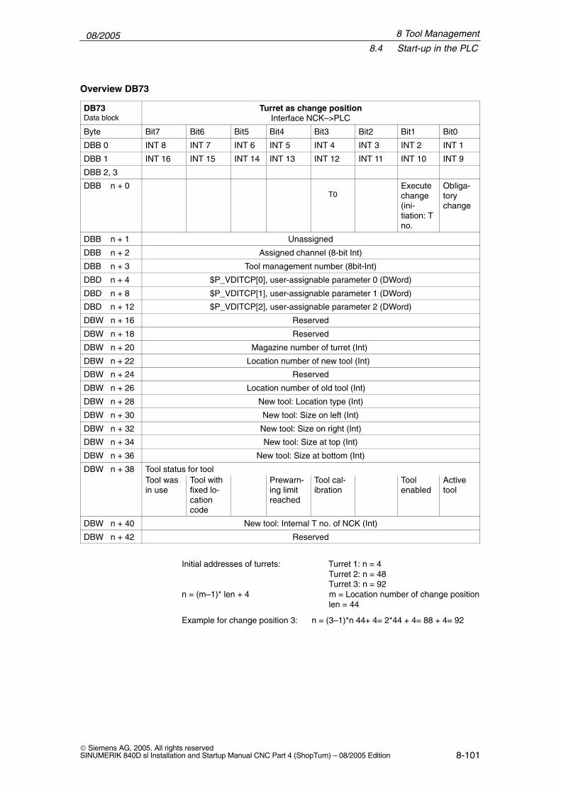
08/20058.4 Start-up in the PLC
8-101 Siemens AG, 2005. All rights reservedSINUMERIK 840D sl Installation and Startup Manual CNC Part 4 (ShopTurn) – 08/2005 Edition
DB73Data block
Turret as change positionInterface NCK–>PLC
Byte Bit7 Bit6 Bit5 Bit4 Bit3 Bit2 Bit1 Bit0
DBB 0 INT 8 INT 7 INT 6 INT 5 INT 4 INT 3 INT 2 INT 1
DBB 1 INT 16 INT 15 INT 14 INT 13 INT 12 INT 11 INT 10 INT 9
DBB 2, 3
DBB n + 0T0
Executechange(ini-tiation: Tno.
Obliga-torychange
DBB n + 1 Unassigned
DBB n + 2 Assigned channel (8-bit Int)
DBB n + 3 Tool management number (8bit-Int)
DBD n + 4 $P_VDITCP[0], user-assignable parameter 0 (DWord)
DBD n + 8 $P_VDITCP[1], user-assignable parameter 1 (DWord)
DBD n + 12 $P_VDITCP[2], user-assignable parameter 2 (DWord)
DBW n + 16 Reserved
DBW n + 18 Reserved
DBW n + 20 Magazine number of turret (Int)
DBW n + 22 Location number of new tool (Int)
DBW n + 24 Reserved
DBW n + 26 Location number of old tool (Int)
DBW n + 28 New tool: Location type (Int)
DBW n + 30 New tool: Size on left (Int)
DBW n + 32 New tool: Size on right (Int)
DBW n + 34 New tool: Size at top (Int)
DBW n + 36 New tool: Size at bottom (Int)
DBW n + 38 Tool status for toolTool wasin use
Tool withfixed lo-cationcode
Prewarn-ing limitreached
Tool cal-ibration
Toolenabled
Activetool
DBW n + 40 New tool: Internal T no. of NCK (Int)
DBW n + 42 Reserved
Initial addresses of turrets: Turret 1: n = 4 Turret 2: n = 48 Turret 3: n = 92
n = (m–1)* len + 4 m = Location number of change positionlen = 44
Example for change position 3: n = (3–1)*n 44+ 4= 2*44 + 4= 88 + 4= 92
Overview DB73
8 Tool Management

08/20058.4 Start-up in the PLC
8-102 Siemens AG, 2005. All rights reserved
SINUMERIK 840D sl Installation and Startup Manual CNC Part 4 (ShopTurn) – 08/2005 Edition
Note
For a description of data blocks DB71 and DB74, please seeReferences: /FBW/, Description of Functions Tool Management
8 Tool Management

08/20058.4 Start-up in the PLC
8-103 Siemens AG, 2005. All rights reservedSINUMERIK 840D sl Installation and Startup Manual CNC Part 4 (ShopTurn) – 08/2005 Edition
DB73 – DBX 0.0 – 0.15 Active status of interface 1–16
Edge evaluation Signal(s) updated: Conditional Signal(s) valid from SW release: 2
Signal status 1 Associated interface has a valid data block
Signal status 0 Operation for this interface has ended. Is reset by FC 7.
DB73.DBX(n+0).0 Command code: Obligatory change
Edge evaluation Signal(s) updated: Conditional Signal(s) valid from SW release: 2
Signal status 1
Signal status 0
Corresponding to... Position of tools involved
DB73.DBX(n+0).1 Command code: Execute change
Edge evaluation Signal(s) updated: Conditional Signal(s) valid from SW release: 2
Signal status 1 Execute tool change
Signal status 0
DB73.DBB(n+0).3 T0
Edge evaluation Signal(s) updated: Conditional Signal(s) valid from SW release: 2
Meaning Indicates that T0 has been programmed.
DB73.DBB(n+2) Assigned channel
Edge evaluation Signal(s) updated: Conditional Signal(s) valid from SW release: 2
Meaning Number of the channel from which the T word was programmed.
DB73.DBB(n+3) Tool management number
Edge evaluation Signal(s) updated: Conditional Signal(s) valid from SW release: 2
Meaning Associated tool management number (TO area) of channel
Note
The bits in DBB (n+0) (obligatory change, execute change,...) are not reset bythe system. They are only current if the corresponding interface bit in DBB0 isset to “1’’. However, these bits can if necessary be reset by the user.
Description DB73
8 Tool Management

08/20058.4 Start-up in the PLC
8-104 Siemens AG, 2005. All rights reserved
SINUMERIK 840D sl Installation and Startup Manual CNC Part 4 (ShopTurn) – 08/2005 Edition
DB73.DBD(n+4) User-assignable parameter 0 (DInt)
Edge evaluation Signal(s) updated: Conditional Signal(s) valid from SW release: 2
Meaning If you need to send a value to the PLC via the part program, the transfer canbe programmed with $P_VDITCP[0]=(value). Parameters 0–2 are transferredwith the T command.
DB73.DBD(n+8) User-assignable parameter 1 (DInt)
Edge evaluation Signal(s) updated: Conditional Signal(s) valid from SW release: 2
Meaning If you need to send a value to the PLC via the part program, the transfer canbe programmed with $P_VDITCP[1]=(value);.
DB73.DBD(n+12) User-assignable parameter 2 (DInt)
Edge evaluation Signal(s) updated: Conditional Signal(s) valid from SW release: 2
Meaning If you need to send a value to the PLC via the part program, the transfer canbe programmed with $P_VDITCP[2]=(value);.
DB73.DBW(n+16) Reserved
Edge evaluation Signal(s) updated: Conditional Signal(s) valid from SW release: 2
DB73.DBW(n+18) Reserved
Edge evaluation Signal(s) updated: Conditional Signal(s) valid from SW release: 2
DB73.DBW(n+20) Magazine number of new tool
Edge evaluation Signal(s) updated: Conditional Signal(s) valid from SW release: 2
Meaning Magazine number of the new tool to be used for machining.
Corresponding to... DBW(n+22)
DB73.DBW(n+22) Location number of new tool to be loaded
Edge evaluation Signal(s) updated: Conditional Signal(s) valid from SW release: 2
Meaning Location number of the new tool to be used for machining.
Corresponding to... DBW(n+20)
DB73.DBW(n+24) Reserved
Edge evaluation Signal(s) updated: Conditional Signal(s) valid from SW release: 2
8 Tool Management

08/20058.4 Start-up in the PLC
8-105 Siemens AG, 2005. All rights reservedSINUMERIK 840D sl Installation and Startup Manual CNC Part 4 (ShopTurn) – 08/2005 Edition
DB73.DBW(n+26) Location number of old tool to be unloaded
Edge evaluation Signal(s) updated: Conditional Signal(s) valid from SW release: 2
Meaning Location number of the old tool (used for machining up till now)
DB73.DBW(n+28) New tool: Location type
Meaning The location type of the new tool is entered here.
Corresponding to... Tool size: Left, right, top, bottom
DB73.DBW(n+30) New tool: Size on left (Int)
Edge evaluation Signal(s) updated: Conditional Signal(s) valid from SW release: 2
Meaning Specification of the size of the new tool on left in half locations.
DB73.DBW(n+32) New tool: Size on right (Int)
Edge evaluation Signal(s) updated: Conditional Signal(s) valid from SW release: 2
Meaning Specification of the size of the new tool on right in half locations.
DB73.DBW(n+34) New tool: Size at top
Edge evaluation Signal(s) updated: Conditional Signal(s) valid from SW release: 2
Meaning Specification of the size of the new tool at top in half locations.
DB73.DBW(n+36) New tool: Size at bottom
Edge evaluation Signal(s) updated: Conditional Signal(s) valid from SW release: 2
Meaning Specification of the size of the new tool at bottom in half locations.
8 Tool Management

08/20058.4 Start-up in the PLC
8-106 Siemens AG, 2005. All rights reserved
SINUMERIK 840D sl Installation and Startup Manual CNC Part 4 (ShopTurn) – 08/2005 Edition
DB73.DBW(n+38) Tool status for new tool
Edge evaluation Signal(s) updated: Conditional Signal(s) valid from SW release: 2
Meaning Bit 0: Active toolBit 1: Tool enabledBit 2: Tool disabledBit 3: Tool calibrationBit 4: Prewarning limit reachedBit 5: Tool is being changedBit 6: Tool is fixed-location-codedBit 7: Tool was in use
DB73.DBW(n+40) New tool: Internal T no. of NCK
Edge evaluation Signal(s) updated: Conditional Signal(s) valid from SW release: 2
Meaning Display of internal T no. of NCK for the new tool. Using this T no. tool manage-ment variables can be read / written via FB2/FB 3.
DB73.DBW(n+42) Reserved
Edge evaluation Signal(s) updated: Conditional Signal(s) valid from SW release: 2
8 Tool Management

08/20058.5 Display machine data
8-107 Siemens AG, 2005. All rights reservedSINUMERIK 840D sl Installation and Startup Manual CNC Part 4 (ShopTurn) – 08/2005 Edition
8.5 Display machine data
Display machine data can be used to activate certain functions and settings atthe operator interface.
MD 9450 $MM_WRITE_TOA_FINE_LIMITLimit value for fine wear
MD 9478 $MM_TO_OPTION_MASK Settings for ShopTurn
MD 9639 $MM_CTM_MAX_TOOL_WEARUpper input limit for tool wear
MD 9651 $MM_CMM_TOOL_MANAGEMENTTool management variant
MD 9652 $MM_CMM_TOOL_LIFE_CONTROL Tool monitoring
MD 9663 $MM_CMM_TOOL_DISPLAY_IN_DIAM Radius / diameter display for tool
MD 9667 $MM_CMM_FOLLOW_ON_TOOL_ACTIVE Tool preselection active
MD 9671 $MM_CMM_TOOL_LOAD_DEFAULT_MAG Load tool in default magazine
MD 9672 $MM_CMM_FIXED_TOOL_PLACE Fixed location coding
MD 9673 $MM_CMM_TOOL_LOAD_STATION Number of loading point
MD 9674 $MM_CMM_ENABLE_TOOL_MAGAZINEDisplay of magazine list
MD 9687 $MM_CMM_TOOL_MOVE_DEFAULT_MAGRelocate tool to default magazine
For the defaults and description of this machine data please refer to Section 7.2“Display machine data for ShopTurn”.
8 Tool Management

08/20058.6 Enable spindle and coolant
8-108 Siemens AG, 2005. All rights reserved
SINUMERIK 840D sl Installation and Startup Manual CNC Part 4 (ShopTurn) – 08/2005 Edition
8.6 Enable spindle and coolant
Here you can assign a direction of rotation (CW / CCW / OFF) and coolant to atool.
“Spindle CW / CCW / OFF”
“Coolant 1 / 2 ON / OFF”
Fig. 8-2 Tool list: Coolant and direction of spindle rotation
Coolants are assigned to the appropriate M commands via the following ma-chine data:MD 9680 $MM_CMM_M_CODE_COOLANT_IMD 9681 $MM_CMM_M_CODE_COOLANT_IIMD 9668 $MM_CMM_M_CODE_COOLANT_I_AND_IIMD 9686 $MM_CMM_M_CODE_COOLANT_OFF
8 Tool Management

08/20058.7 Moving the turret manually
8-109 Siemens AG, 2005. All rights reservedSINUMERIK 840D sl Installation and Startup Manual CNC Part 4 (ShopTurn) – 08/2005 Edition
8.7 Moving the turret manually
To bring another tool located in the turret into machining position, move the tur-ret manually via the machine control panel. Any manual movement must bereported to the NCK so that the correction values for the new tool can be calcu-lated. You can implement this check-back signal providing that the option “ac-tions that go across modes (asynchronous subprograms ASUB and synchro-nized actions in all modes)” is set (order no. 6FC5 800-0AM43-0YB0).
Press key “Turn turret”on the MCP
The turret turns
The turret latches into the new position
PLC block(TM_REV_M.AWL)
is activated
FB 4 (PI service ASUB)
FC 9(ASUB call)
ASUB(TM_REV_M.SPF)
ASUB reads the newtool from the actual
position(analog input 1)
ASUB activates a newtool correction
PLC block writesactual position
to analog input 1
ErrorStart
Actualposition
Done
Fig. 8-3 Example of check-back signal from tool number to NCK
8 Tool Management

08/20058.7 Moving the turret manually
8-110 Siemens AG, 2005. All rights reserved
SINUMERIK 840D sl Installation and Startup Manual CNC Part 4 (ShopTurn) – 08/2005 Edition
The ASUB derives the tool number from the location number (actual position)that it has received from the PLC block and forwards this to the NCK.
The toolbox contains the sources TM_REV_M_GR.AWL in Germanmnemonics, TM_REV_M_UK.AWL in English mnemonics, and the ASUB TM_REV_M.SPF.The PLC block and ASUB use interrupt 8 and analog input 1. Please set thefollowing machine data:
MD 11602 $MN_ASUP_START_MASK = H3Ignore stop reasons for ASUB
MD 11604 $MN_ASUP_START_PRIO_LEVEL = H64Priorities for MD 11602 $MN_ASUP_START_MASK effective
MD 20116 $MC_IGNORE_INHIBIT_ASUP, bit 7 = 1 (ASUB on interrupt 8 can always be executed.)If another interrupt number is used, the corresponding bit must be set.
MD 10300 $MN_FASTIO_ANA_NUM_INPUTS = Total number of analog inputsused.
MD 10320[0] $MN_FASTIO_ANA_INPUT_WEIGHT = 32767 Weighting of the analog input (index 0 corresponds to input 1)
You might have to adapt the PLC block and the ASUB. Please note the follo-wing:
� Assign new block numbers in the symbols table.
� Make sure that the interrupt numbers are identical when you initialize (FB4call) and call them (FC9 call) (default setting 8).
� If necessary, adapt the interface signals to the analog input.
� Compile and load the TM_REV_M.
� Call up the function block in the user PLC and parameterize it.
� Set interface VAR_INPUT to start and combine the VAR_OUTPUT signalsfor the check-back signal of the block in your user PLC.
� In your user PLC make sure that the tool turret cannot be restarted manuallywhile an ASUB is being executed. This would otherwise cause the incorrectactual turret position to be detected.
Note
Calling the TM_REV_M.SPF starts a new tool change call (change request atturret interface in DB 73). If all is correct, setpoint position = actual position andno further movement of the turret is triggered. However, if an incorrect actualposition is returned, this could cause the turret to swivel again. You shouldtherefore only permit manual movement of the turret in NCK mode JOG andonly permit the change request via the interface signal in DB 73 in NCK modeAUTO.
8 Tool Management

08/20058.7 Moving the turret manually
8-111 Siemens AG, 2005. All rights reservedSINUMERIK 840D sl Installation and Startup Manual CNC Part 4 (ShopTurn) – 08/2005 Edition
Note
If you permit manual movement of the turret – even if the program has not beeninterrupted, you must ensure that the ASUB is executed without error and thatthe interrupted program can be resumed.
8 Tool Management

08/20058.8 Configuring the operator interface
8-112 Siemens AG, 2005. All rights reserved
SINUMERIK 840D sl Installation and Startup Manual CNC Part 4 (ShopTurn) – 08/2005 Edition
8.8 Configuring the operator interface
There are two ways you can modify the existing operator interface for the toolmanagement system:
� In tool management, in addition to the tools, wear, and magazine lists, anadditional list can also be activated on the 3rd horizontal softkey; (see Sub-section 8.8.1 “Integrating additional list”).
� In these lists, depending on the tool, all existing or user-defined parameterscan be configured; (see Subsection 8.8.2 “Modifying lists”).
8.8.1 Integrating additional list
To activate an additional list proceed as follows:
� Set machine data9478 $MM_TO_OPTION_MASK, Bit 2 = 1Activate additional list
In tool management you can now, by means of the 3rd horizontal softkey,call up a list with the following parameters :– “Length Y”– “Wear length Y” – “H number”
Parameter “H number” will only be displayed if ShopTurn is set up for ISOdialects (see Section 11.4 “ISO dialects”).
� Specify texts for the additional list (optional)If you want to change the softkey labeling (OEM tool list) and header (OEMtool list) for the additional list, you must specify new texts; (see Subsec-tion 8.8.4 “Specifying texts”).
8 Tool Management

08/20058.8 Configuring the operator interface
8-113 Siemens AG, 2005. All rights reservedSINUMERIK 840D sl Installation and Startup Manual CNC Part 4 (ShopTurn) – 08/2005 Edition
8.8.2 Configuring lists
To modify existing lists (including an integrated additional list) you must proceedas follows:
Set the following machine data:
MD 9478 $MM_TO_OPTION_MASK, Bit 8Evaluate file TO_TURN.INI
The configuration file TO_TURN.INI in which you can configure changes withrespect to the default settings, is evaluated; (see Subsection 8.8.3 “Creating theconfiguration file”).
If you use user-defined OEM data, set the following machine data:
MD 18080 $MN_MM_TOOL_MANAGEMENT_MASK, Bit 2Provide memory for user data
MD 18094 $MN_MM_NUM_CC_TDA_PARAMNumber of user-defined parameters
MD 18095 $MN_MM_TYPE_CC_TDA_PARAM[n]=4Data type (REAL) of user-defined parameters
MD 20310 $MC_TOOL_MANAGEMENT_MASK, Bit 2Activate user functions
Texts for user-defined parameters (optional)To modify the column headers and cursor texts for the user-defined parametersyou must specify new texts; (see Subsection 8.8.4 “Specifying texts”).
Specify all changes changes with respect to the default settings in the configu-ration file TO_TURN.INI; (see Subsection 8.8.3 “Creating the configuration file”).
Activate theconfiguration file
Activate use ofOEM data
Adapt theconfiguration file
8 Tool Management

08/20058.8 Configuring the operator interface
8-114 Siemens AG, 2005. All rights reserved
SINUMERIK 840D sl Installation and Startup Manual CNC Part 4 (ShopTurn) – 08/2005 Edition
8.8.3 Creating the configuration file
You must save all changes made in the lists with respect to the default setting inconfiguration file TO_TURN.INI.
Please note the following:
� After the column “DP number” you can define further columns and also hideexisting columns.
� The number of columns displayed is limited by the width of the window be-cause each column has a fixed width. Horizontal scrolling is not possible.
� Per column define cutting edge parameters only, tool parameters only, ormagazine parameters only.
� Define the cutting edge parameters in consecutive columns.
The example file TO_TURN.INI that you can adapt is located in ShopTurn onNCU (HMI embedded) in directory ZYKLENABLAGE\SCHRITTKETTENZYKLEN\TEMPLATES_DEU.The system than searches for adapted file on the CF card (NCU 7x0) in direc-tory – oem\sinumerik\hmi\cfg\ and directory – user\sinumerik\hmi\cfg\.
With ShopTurn on PCU 50.3 the example is located on the delivery CD in direc-tory Tools\TEMPLATES_DEU.Store the file in the OEM directory or the USER directory.
Entries in the configuration file are subject to the following syntax rules; (seealso example at end of this Section):
First specify in which tool management list you would like to make changes.[DISPLAY_IDENTIFIER]
DISPLAY_IDENTIFIER: Tool management list
Syntax
8 Tool Management

08/20058.8 Configuring the operator interface
8-115 Siemens AG, 2005. All rights reservedSINUMERIK 840D sl Installation and Startup Manual CNC Part 4 (ShopTurn) – 08/2005 Edition
Next define the changes themselves:
� Modify a specific column for all tools:COLUMNx=CONTENTS_IDENTIFIER
COLUMN: Column commandx: Column number, 1 – 12 CONTENTS_IDENTIFIER: Parameter or property of tool
� Modify a specific column for a specific tool:TOOL_IDENTIFIER = x=CONTENTS_IDENTIFIER
TOOL_IDENTIFIER: Tool type
� Define different columns for each tool:WERKZEUG_KENNUNG = INHALT_KENNUNG / INHALT_KENNUNG / ...WERKZEUG_KENNUNG = INHALT_KENNUNG / INHALT_KENNUNG / ......
The parameters or properties of a tool are listed one after the other bymeans of a CONTENTS_IDENTIFIER and are separated from one anotherby a forward slash “/”. If the default setting is to be used for individual col-umns, you still need to insert a forward slash.
If, for example, you only want to modify the last few columns, specify thenumber (x) of the first column you would like to modify and list the respectiveCONTENTS_IDENTIFIERs for the subsequent columns.TOOL_IDENTIFIER = x=CONTENTS_IDENTIFIER / CONTENTS_IDEN-TIFIER / ..
Note
Using the COLUMN command, you can first define one column identically forall tools and then adapt it specifically for individual tools.
You can mark comments by means of a semicolon (;) symbol.
If errors occur during evaluation of the configuration file, refer to theTO_INI_F.LOG file for a description of the error. With ShopTurn on NCU (HMIembedded) the file is located in drive I: and with the PCU 50.3 n directoryF:\MMC0W32\TMP.
The following tables list the SCREEN_ IDENTIFIERS, TOOL_ IDENTIFIERS,and CONTENTS_ IDENTIFIERS available for defining the columns.
Table 8-2 SCREEN_IDENTIFIER
SCREEN_IDENTIFIER Tool management list
TOOL_LIST Tool list
TOOL_LIST_2ND_EDGE Tool list, further cutting edges
TOOL_WEAR Tool wear list
TOOL_WEAR_2ND_EDGE Tool wear list, further cutting edges
TOOL_MAGA Magazine list
TOOL_LIST_OEM Additional list
TOOL_LIST_OEM_2ND_EDGE Further cutting edges
Identifier
8 Tool Management

08/20058.8 Configuring the operator interface
8-116 Siemens AG, 2005. All rights reserved
SINUMERIK 840D sl Installation and Startup Manual CNC Part 4 (ShopTurn) – 08/2005 Edition
Table 8-3 TOOL_IDENTIFIER
TOOL_IDENTIFIER Tool
SHANK_END_CUTTER_TR (End) cutter
END_MILL_CUTTER_TR Facing tool
POINTED_DRILL_TR (Twist) drill
ROUGHER Roughing tool
FINISHER Finishing tool
PARTING_OFF Plunge cutter
SCREW_CUTTER Threading tool
BUTTON Button tool
STOPPER Stop
TURN_DRILL Rotary drill
TO_SCREW_TAP_TR Screw tap
3DTRACER_TR 3D probe
Table 8-4 CONTENT_ID
CONTENT_IDParameter
type *
Parameter or property Fieldwidth innumberof char-acters
EMPTY Empty field
NOT_USED Empty column
LENGTH1 S Length X 7
LENGTH2 S Length Z 7
LENGTH3 S Length Y 7
RADIUS S Radius 7
RADIUS_DIAM
SRadius with possible diameter calculation
7
RADIUS_DIAM9
SRadius with possible diameter calculation– rotary drill bit radius
5
ANGLE_TR S Angle 5
CUTTDIR S Reference direction for holder angle 1
PLATELEN S Tip length 5
PLATEWID S Tip width 5
PLATEANG S Tip angle 2
PITCH S Pitch for screw tap 5
HOLDERANG S Holder angle 5
N S Number of teeth 2
SPINDLE S Spindle direction 1
COOL1 S Cooling water 1 1
COOL2 S Cooling water 2 1
DLENGTH1 S Wear length X 7
DLENGTH2 S Wear length Z 7
DLENGTH3 S Wear length Y 7
8 Tool Management

08/20058.8 Configuring the operator interface
8-117 Siemens AG, 2005. All rights reservedSINUMERIK 840D sl Installation and Startup Manual CNC Part 4 (ShopTurn) – 08/2005 Edition
Table 8-4 CONTENT_ID
CONTENT_ID Fieldwidth innumberof char-acters
Parameter or propertyParameter
type *
DRADIUS S Wear radius 6
DRADIUS_DIAM
SWear radius with possible diameter cal-culation
6
T_OR_C W Method of wear monitoring 1
P_TIME S Tool life 7
PW_TIME S Prewarning limit for tool life 7
P_COUNT S Quantity 7
PW_COUNT S Prewarning limit quantity 7
P_WEAR S Wear 7
PW_WEAR S Prewarning limit for wear 7
T_LOCKED W Tool disabled 1
T_SIZE W Oversized tool 1
T_FIXED W Tool in fixed location 1
T_STATEW
Status display: Active / prewarning limitreached / blocked
5
T_SIZE_LONG
W
Tool sizeThis parameter is not contained in theShopTurn standard tool list.
Column header: LROUCursor text: Tool sizeInput: Number of adjacent half locations(maximum 7) to be blocked. The first halflocation is always the magazine location inwhich the tool is mounted. The number ofadjacent half locations is specified as afour-digit number. The first digit is the num-ber of adjacent locations to the left, thesecond to the right, the third above, andthe fourth below. Requirement input: The tool must be lo-cated outside a magazine.
4
T_MAG_PLACE_TYPE
W
Magazine location typeThis parameter is not contained in theShopTurn standard tool list.Column header: Location typeCursor text: Magazine location typeInput: Number of magazine location typeRequirement input:The tool must be lo-cated outside a magazine.
5
P_LOCKED M Magazine location locked 6
MAG_T_LOCKED
WDisplay only: Tool disabled
1
MAG_T_SIZE W Display only: Oversized tool 1
MAG_T_FIXED
WDisplay only: Tool in fixed location
1
H_NBR S H number of an ISO dialect program 3
8 Tool Management

08/20058.8 Configuring the operator interface
8-118 Siemens AG, 2005. All rights reserved
SINUMERIK 840D sl Installation and Startup Manual CNC Part 4 (ShopTurn) – 08/2005 Edition
Table 8-4 CONTENT_ID
CONTENT_ID Fieldwidth innumberof char-acters
Parameter or propertyParameter
type *
TPC1 W Parameter 1 7
TPC2 W Parameter 2 7
TPC3 W Parameter 3 7
TPC4 W Parameter 4 7
TPC5 W Parameter 5 7
TPC6 W Parameter 6 7
TPC7 W Parameter 7 7
TPC8 W Parameter 8 7
TPC9 W Parameter 9 7
TPC10 W Parameter 10 7
* Parameter types: S = cutting edge data, W = tool data, M = magazine data.
Parameter “H number” will only be displayed if ShopTurn is set up for ISO dia-lects (see Section 11.4 “ISO Dialects”).
;============================================[TOOL_LIST_OEM] ; screen OEM tool list;=============================================;Default values for columnsCOLUMN1 = LENGTH3COLUMN2 = DLENGTH3COLUMN3 = TPC1COLUMN4 = TPC2COLUMN5 = NOT_USEDCOLUMN6 = NOT_USEDYCOLUMN7 = NOT_USEDCOLUMN8 = NOT_USEDCOLUMN9 = NOT_USEDCOLUMN10= NOT_USEDCOLUMN11= NOT_USEDCOLUMN12= NOT_USED
Example
8 Tool Management

08/20058.8 Configuring the operator interface
8-119 Siemens AG, 2005. All rights reservedSINUMERIK 840D sl Installation and Startup Manual CNC Part 4 (ShopTurn) – 08/2005 Edition
In the example list the following columns are to be displayed:Column 1: Tool length YColumn 2: Wear YColumn 3: 1st user-specific parameterColumn 4: 2nd user-specific parameter
For this example you have set the following machine data:
MD 18080 $MN_MM_TOOL_MANAGEMENT_MASK, Bit 2Provide memory for user data
MD 18094 $MN_MM_NUM_CC_TDA_PARAM=2For the two user-defined parameters (TPC1 and TPC2)
MD 18095 $MN_MM_TYPE_CC_TDA_PARAM[n]=4Data type (REAL) of user-defined parameters
MD 20310 $MC_TOOL_MANAGEMENT_MASK, Bit 2Activate user functions
8 Tool Management

08/20058.8 Configuring the operator interface
8-120 Siemens AG, 2005. All rights reserved
SINUMERIK 840D sl Installation and Startup Manual CNC Part 4 (ShopTurn) – 08/2005 Edition
8.8.4 Define texts
Texts (softkey name and list header for additional lists, column headers, andcursor texts for user-defined parameters) are assigned to specific text numbersin a text file.
These are subject to the following syntax:Text number 0 0 “Text”
The two parameters 2 and 3 separated by blanks are control characters for textoutput and must always be set to 0.
The column header in the parameter name can consist of three lines, each linewith its own text number; (see Table 8-5).
Table 8-5 Text assignment
Text type Text number
3. Horizontal softkey 89923
List header 89924
Column header parameter TPC1 89925, 89926, 89927
Cursor text parameter TPC1 89931
Column header parameter TPC2 89928, 89929, 89930
Cursor text parameter TPC2 89932
Column header parameter TPC3 89953, 89954, 89955
Cursor text parameter TPC3 89965
Column header parameter TPC4 89937, 89938, 89939
Cursor text parameter TPC4 89949
Column header parameter TPC5 89940, 89941, 89942
Cursor text parameter TPC5 89950
Column header parameter TPC6 89943, 89944, 89945
Cursor text parameter TPC6 89951
Column header parameter TPC7 89956, 89957, 89958
Cursor text parameter TPC7 89966
Column header parameter TPC8 89946, 89947, 89948
Cursor text parameter TPC8 89952
Column header parameter TPC9 89959, 89960, 89961
Cursor text parameter TPC9 89967
Column header parameter TPC10 89962, 89963, 89964
Cursor text parameter TPC10 89968
Example:89924 0 0 ”Tool data”
The texts must not exceed the following number of characters:Softkey: 6List header: 20Column header parameter: 7Cursor text parameter: 45
8 Tool Management

08/20058.8 Configuring the operator interface
8-121 Siemens AG, 2005. All rights reservedSINUMERIK 840D sl Installation and Startup Manual CNC Part 4 (ShopTurn) – 08/2005 Edition
A line break in the softkey text can be made by inserting two consecutiveblanks.
Note
The columns for parameters TPC1 and TPC2 are already preset with exampletexts; these can be modified.
With ShopTurn on NCU (HMI embedded) enter the texts and numbers in thetext file ALUC.TXT. There is an ALUC.TXT text file in each language directory.
With the PCU 50.3 enter the texts and numbers in the text fileF:\DH\CUS.DIR\ALUC_xx.COM. If the ALUC_xx.COM file does not exist, youneed to create it in the CUS.DIR directory.The texts are assigned to a language by means of the text file name. In the textfile name ”xx” is replaced by one of the following codes:
Table 8-6 Language assignment
AbbreviationXX
Language
gr German
uk English
fr French
it Italian
sp Spanish
nl Dutch
dk Danish
fi Finnish
sw Swedish
pl Polish
tr Turkish
ch Simplified Chinese
tw Chinese (Traditional)
ko Korean
hu Hungarian
po Brazilian Portuguese
ru Russian
cz Czech
ja Japanese
In the file F:\USER\MBDDE.INI or F:\OEM\MBDDE.INI add the following line inthe Section [TextFiles]:UserZYK=F:\dh\cus.dir\aluc_
ShopTurn on NCU(HMI embedded)
PCU 50.3
8 Tool Management

08/20058.9 Importing tool data
8-122 Siemens AG, 2005. All rights reserved
SINUMERIK 840D sl Installation and Startup Manual CNC Part 4 (ShopTurn) – 08/2005 Edition
8.9 Importing tool data
Tool data that has been defined on an external tool presetting device can beimported directly into ShopTurn tool management.
Save the tool data as an INI file.
The header in the file must be exactly as follows:
;TOOL MAGAZIN ZEROPOINT,TOOL=2,MAGAZIN=0,NPV=0,BNPV=0
However, you can modify the values for ”Tool” and ”Magazine”.
Tool=1: Delete all existing tools in tool management and replace with new tools.
Tool=2: Add new tools to tool managementMagazine=0: Do not evaluate magazine location number ($TC_MPP6)Magazine=1: Evaluate magazine location number ($TC_MPP6)
Note
Always keep to the precise order (including blanks) in the header. If you enteran incorrect header line, the INI file on opening will be evaluated as a G codeprogram. Starting the program with ”Cycle start” causes existing data in toolmanagement to be overwritten by the data contained in the program.
The tool data must be assigned the following variables in the INI file, where:x = tool numbery = cutting edge number
Table 8-7 Variable assignment
Variable Meaning Value
$TC_TP1[x] Duplo number Number
$TC_TP2[x] Tool name Name
$TC_TP3[x] Number of adjacent half locations onthe left to be blocked for oversizedtools.
ShopTurn default setting 1 = Do not block adjacent locationor2 = Block half of adjacent location on the left
$TC_TP4[x] Number of adjacent half locations onthe right to be blocked for oversizedtools.
ShopTurn default setting 1 = Do not block adjacent locationor2 = Block half of adjacent location on the right
$TC_TP5[x] Number of adjacent half locationsabove to be blocked for oversizedtools.
ShopTurn default setting 1 = Do not block adjacent location
$TC_TP6[x] Number of adjacent half locations be-low to be blocked for oversized tools.
ShopTurn default setting 1 = Do not block adjacent location
$TC_TP7[x] Magazine location type Number
$TC_TP8[x] Tool status Bit 1 = 1: Tool enabledBit 2 = 1: Tool disabledBit 4 = 1: Prewarning limit reached
8 Tool Management

08/20058.9 Importing tool data
8-123 Siemens AG, 2005. All rights reservedSINUMERIK 840D sl Installation and Startup Manual CNC Part 4 (ShopTurn) – 08/2005 Edition
Table 8-7 Variable assignment
Variable ValueMeaning
$TC_TP9[x] Tool monitoring Bit 0 = 1: Tool life monitoring activeBit 1 = 1: Workpiece count monitoring activeBit 2 = 1: Wear monitoring active
$TC_TPC1[x] User-defined parameter 1
$TC_TPC2[x] User-defined parameter 2
$TC_TPC3[x] User-defined parameter 3
$TC_TPC4[x] User-defined parameter 4
$TC_TPC5[x] User-defined parameter 5
$TC_TPC6[x] User-defined parameter 6
$TC_TPC7[x] User-defined parameter 7
$TC_TPC8[x] User-defined parameter 8
$TC_TPC9[x] User-defined parameter 9
$TC_TPC10[x] User-defined parameter 10
$TC_DP1[x,y] Tool type 120: Milling cutter140: Facing tool200: Drill 240: Screw tap500: Roughing tools510: Finishing tools520: Plunge-cutter540: Threading tool550: Button560: Rotary drill580: 3D probe750: Stop
$TC_DP2[x,y] Cutting edge position When machining behind the turning center, thetool tip is pointing to:1: Top right2: Top left3: Bottom left4: Botton right5: Right6: Top7: Left8: Bottom9: Tool tip = tool nose center
$TC_DP3[x,y] Length X Number [mm]
$TC_DP4[x,y] Length Z Number [mm]
$TC_DP5[x,y] Length Y Number [mm]
$TC_DP6[x,y] Radiusorinternal radius (facing tool)
Number [mm]
Number [mm]
$TC_DP7[x,y] External radius Number [degrees]
$TC_DP8[x,y] Tip length Number [mm]
$TC_DP9[x,y] Tip width Number [mm]
$TC_DP10[x,y] Holder angle Number [degrees]
8 Tool Management

08/20058.9 Importing tool data
8-124 Siemens AG, 2005. All rights reserved
SINUMERIK 840D sl Installation and Startup Manual CNC Part 4 (ShopTurn) – 08/2005 Edition
Table 8-7 Variable assignment
Variable ValueMeaning
$TC_DP11[x,y] Reference direction for holder angle
ortool angle / chamfer angle (facingtool)
1: Traversing motion in negative direction, x–2: Traversing motion in positive direction, x+3: Longitudinal travel in negative direction, z–4: Longitudinal travel in positive direction, z+
number [degrees]
$TC_DP12[x,y] Wear length X Number [mm]
$TC_DP13[x,y] Wear length Z Number [mm]
$TC_DP14[x,y] Wear length Y Number [mm]
$TC_DP15[x,y] Wear radius Number [mm]
$TC_DP24[x,1]
$TC_DP24[x,y]
$TC_DP24[x,y]
Number of teeth (milling tool)or tool tip angle (drill)ortool clearance angle (turning tool)ShopTurn calculates the tip anglefrom the tool clearance angle and dis-plays this in tool management: Tip angle = 180 – tool clearanceangle – holder angle.
Number
Number [degrees]
Number [degrees]
$TC_DP25[x,1] Direction of spindle rotation
Coolant
M function
Bit 8 and bit 9 = 0: Spindle stopBit 8 = 1: Spindle rotates clockwiseBit 9 = 1: Spindle rotates counter-clockwiseBit 10 = 1: Cooling water 1 ONBit 11 = 1: Cooling water 2 ONBit 0 = 1: M function 1Bit 1 = 1: M function 2Bit 2 = 1: M function 3Bit 3 = 1: M function 4
$TC_DPH[x,y] H number of an ISO dialect program Number
$TC_MOP1[x,y] Prewarning limit for tool life Number [min]
$TC_MOP2[x,y] Tool life Number [min]
$TC_MOP3[x,y] Prewarning limit quantity Number
$TC_MOP4[x,y] Quantity Number
$TC_MOP5[x,y] Prewarning limit for wear Number [mm]
$TC_MOP15[x,y] Maximum wear Number [mm]
$TC_MPP6[n,m] Magazine location number Numbern: Magazine numberm: Magazine location number
For bit-coded parameters you must specify a hexadecimal value.
The H number for ISO dialect programs will only be evaluated if ShopTurn is setup for ISO dialects (see Section 11.4 “ISO Dialects”).
If you do not define parameters, tool management will subsequently set them tozero.
You must program the command ”M30” at the end of the file.
For information about importing tool data into tool management, please refer to:References: /BAT/, ShopTurn Operating/Programming Guide
8 Tool Management

08/20058.9 Importing tool data
8-125 Siemens AG, 2005. All rights reservedSINUMERIK 840D sl Installation and Startup Manual CNC Part 4 (ShopTurn) – 08/2005 Edition
;TOOL MAGAZINE ZEROPOINT,TOOL=2,MAGAZINE=0,NPV=0,BNPV=0$TC_TP1[1]=1 ;Duplo number$TC_TP2[1]=ROUGHING TOOL ;Tool ”ROUGHING TOOL”$TC_TP3[1]=1 ;Adjacent location on left
unoccupied$TC_TP4[1]=1 ;Adjacent location on right
unoccupied$TC_TP5[1]=1 ;Adjacent location above unoccupied$TC_TP6[1]=1 ;Adjacent location below unoccupied$TC_TP7[1]=1 ;Magazine location type$TC_TP8[1]=2 ;Tool enabled$TC_TP9[1]=1 ;Tool life monitoring$TC_DP1[1,1]=500 ;Tool type, roughing tool$TC_DP2[1,1]=3 ;Cutting edge position (left
bottom)$TC_DP3[1,1]=35.92 ;Length X$TC_DP4[1,1]=67.89 ;Length Z$TC_DP6[1,1]=0.6 ;Radius$TC_DP8[1,1]=14 ;Tip length$TC_DP10[1,1]=93 ;Holder angle$TC_DP11[1,1]=3.0 ;Reference direction for holder
angle;–Z direction
$TC_DP24[1,1]=2 ;Tool clearance angle...M30 ;End of program
�
Example
8 Tool Management

08/20058.9 Importing tool data
8-126 Siemens AG, 2005. All rights reserved
SINUMERIK 840D sl Installation and Startup Manual CNC Part 4 (ShopTurn) – 08/2005 Edition
8 Tool Management
Notes

9-127 Siemens AG, 2005. All rights reservedSINUMERIK 840D sl Installation and Startup Manual CNC Part 4 (ShopTurn) – 08/2005 Edition
Additional Functions
9.1 Measuring cycle
9.1.1 Brief description
Overview You can use a measuring cycle for automatic measurement of tools on turningmachines with ShopTurn.
This is achieved simply by connecting a touch trigger probe to the control.
References:/FB2/, Description of Functions Extended Functions, Measuring (M5)/GDS/, Device Manual NCU,SINUMERIK 840D sl/IDS/, Commissioning Manual CNC Part 1 (NCK, PLC, Drive), SINUMERIK 840D sl,
The measuring cycle is supplied with ShopTurn.
You have to adapt the measuring cycle data to the specific characteristics of themachine.
The probe operates internally with the command MEAS.
The function test of the probe is conducted using a part program.
References: /PGA/, Programming guide/BNM/, User Manual, Measuring cycles
Measuring cycle
Function test
9

08/20059.1 Measuring cycle
9-128 Siemens AG, 2005. All rights reserved
SINUMERIK 840D sl Installation and Startup Manual CNC Part 4 (ShopTurn) – 08/2005 Edition
9.1.2 Display machine data for measuring cycle
ÁÁÁÁÁÁÁÁÁÁÁÁÁÁÁÁ
9749ÁÁÁÁÁÁÁÁÁÁÁÁÁÁÁÁÁÁÁÁÁÁÁÁÁÁÁÁÁÁÁÁÁÁÁÁÁÁÁÁÁÁÁÁÁÁ
CMM_ENABLE_MEAS_T_AUTOÁÁÁÁÁÁÁÁÁÁÁÁÁÁÁÁ
MD number ÁÁÁÁÁÁÁÁÁÁÁÁÁÁÁÁÁÁÁÁÁÁÁÁÁÁÁÁÁÁÁÁÁÁÁÁÁÁÁÁÁÁÁÁÁÁ
Enable automatic tool measurement
ÁÁÁÁÁÁÁÁÁÁÁÁÁÁÁÁÁÁÁÁÁÁ
Default setting: 1 ÁÁÁÁÁÁÁÁÁÁÁÁÁÁÁÁÁÁÁÁÁÁ
Minimum input limit: 0 ÁÁÁÁÁÁÁÁÁÁÁÁÁÁÁÁÁÁÁÁ
Maximum input limit: 1
ÁÁÁÁÁÁÁÁÁÁÁÁÁÁChanges effective as from NOW ÁÁÁÁÁÁÁÁÁÁÁProtection level: 3/4 ÁÁÁÁÁÁÁUnit: –ÁÁÁÁÁÁÁÁÁÁÁÁÁÁÁÁÁÁÁÁÁÁÁÁÁÁÁÁÁÁÁÁÁÁÁÁÁÁÁÁÁÁÁÁÁÁÁÁÁÁÁ
Data type: WORD ÁÁÁÁÁÁÁÁÁÁÁÁÁÁÁÁÁÁÁÁÁÁÁÁÁÁÁÁÁÁÁÁÁÁÁÁÁÁÁÁÁÁ
Valid as of software version:ShopTurn 6.4
ÁÁÁÁÁÁÁÁÁÁÁÁÁÁÁÁÁÁÁÁÁÁÁÁ
Meaning: ÁÁÁÁÁÁÁÁÁÁÁÁÁÁÁÁÁÁÁÁÁÁÁÁÁÁÁÁÁÁÁÁÁÁÁÁÁÁÁÁÁÁÁÁÁÁÁÁÁÁÁÁÁÁÁÁÁÁÁÁÁÁÁÁÁÁÁÁÁ
This MD is used to enable the “Automatic tool measurement” function on the user interface.0 = “Automatic tool measurement” function is not displayed1 = “Automatic tool measurement” function is displayed
ÁÁÁÁÁÁÁÁÁÁÁÁÁÁÁÁ
9751 ÁÁÁÁÁÁÁÁÁÁÁÁÁÁÁÁÁÁÁÁÁÁÁÁÁÁÁÁÁÁÁÁÁÁÁÁÁÁÁÁÁÁÁÁÁÁ
CMM_MEAS_T_PROBE_INPUT
ÁÁÁÁÁÁÁÁÁÁÁÁÁÁÁÁ
MD number ÁÁÁÁÁÁÁÁÁÁÁÁÁÁÁÁÁÁÁÁÁÁÁÁÁÁÁÁÁÁÁÁÁÁÁÁÁÁÁÁÁÁÁÁÁÁ
Measuring input for tool probe
ÁÁÁÁÁÁÁÁÁÁÁDefault setting: 0 ÁÁÁÁÁÁÁÁÁÁÁMinimum input limit: 0 ÁÁÁÁÁÁÁÁÁÁMaximum input limit: 1ÁÁÁÁÁÁÁÁÁÁÁÁÁÁÁÁÁÁÁÁÁÁÁÁÁÁÁÁ
Changes effective as from NOW ÁÁÁÁÁÁÁÁÁÁÁÁÁÁÁÁÁÁÁÁÁÁ
Protection level: 3/4 ÁÁÁÁÁÁÁÁÁÁÁÁÁÁ
Unit: –ÁÁÁÁÁÁÁÁÁÁÁÁÁÁÁÁÁÁÁÁÁÁÁÁÁÁÁÁÁÁÁÁÁÁ
Data type: BOOL ÁÁÁÁÁÁÁÁÁÁÁÁÁÁÁÁÁÁÁÁÁÁÁÁÁÁÁÁ
Valid as of software version:ShopTurn 6.3ÁÁÁÁÁÁÁÁ
ÁÁÁÁÁÁÁÁÁÁÁÁÁÁÁÁ
Meaning: ÁÁÁÁÁÁÁÁÁÁÁÁÁÁÁÁÁÁÁÁÁÁÁÁÁÁÁÁÁÁÁÁÁÁÁÁÁÁÁÁÁÁÁÁÁÁÁÁÁÁÁÁÁÁÁÁÁÁÁÁÁÁÁÁÁÁÁÁÁ
This MD is used to stipulate the number of the input for the tool probe for the main spindle.0 = Measuring input 1 is activated1 = Measuring input 2 is activated
ÁÁÁÁÁÁÁÁÁÁÁÁÁÁÁÁ
9754 ÁÁÁÁÁÁÁÁÁÁÁÁÁÁÁÁÁÁÁÁÁÁÁÁÁÁÁÁÁÁÁÁÁÁÁÁÁÁÁÁÁÁÁÁÁÁ
CMM_MEAS_DIST_TOOL_LENGTH
ÁÁÁÁÁÁÁÁMD number ÁÁÁÁÁÁÁÁÁÁÁÁÁÁÁÁÁÁÁÁÁÁÁMaximum measurement distance, tool length, rotating spindleÁÁÁÁÁÁÁÁÁÁÁÁÁÁÁÁÁÁÁÁÁÁ
Default setting: 10ÁÁÁÁÁÁÁÁÁÁÁÁÁÁÁÁÁÁÁÁÁÁ
Minimum input limit: 0.001ÁÁÁÁÁÁÁÁÁÁÁÁÁÁÁÁÁÁÁÁ
Maximum input limit: 1000ÁÁÁÁÁÁÁÁÁÁÁÁÁÁÁÁÁÁÁÁÁÁÁÁÁÁÁÁ
Changes effective as from NOW ÁÁÁÁÁÁÁÁÁÁÁÁÁÁÁÁÁÁÁÁÁÁ
Protection level: 3/4 ÁÁÁÁÁÁÁÁÁÁÁÁÁÁ
Unit: mm
ÁÁÁÁÁÁÁÁÁÁÁÁÁÁÁÁÁÁÁÁÁÁÁÁÁÁÁÁÁÁÁÁÁÁ
Data type: DOUBLE ÁÁÁÁÁÁÁÁÁÁÁÁÁÁÁÁÁÁÁÁÁÁÁÁÁÁÁÁ
Valid as of software version:ShopTurn 6.4
ÁÁÁÁÁÁÁÁÁÁÁÁÁÁÁÁÁÁÁÁÁÁÁÁ
Meaning: ÁÁÁÁÁÁÁÁÁÁÁÁÁÁÁÁÁÁÁÁÁÁÁÁÁÁÁÁÁÁÁÁÁÁÁÁÁÁÁÁÁÁÁÁÁÁÁÁÁÁÁÁÁÁÁÁÁÁÁÁÁÁÁÁÁÁÁÁÁ
This MD is used to stipulate the maximum measurement distance before and after the expectedswitching position (tool length) for measuring the tool length with rotating spindle. If no switchingsignal is output within this range the error message “Probe does not switch” is output.
ÁÁÁÁÁÁÁÁ9759 ÁÁÁÁÁÁÁÁÁÁÁÁÁÁÁÁÁÁÁÁÁÁÁCMM_MAX_CIRC_SPEED_ROT_SPÁÁÁÁÁÁÁÁÁÁÁÁÁÁÁÁ
MD numberÁÁÁÁÁÁÁÁÁÁÁÁÁÁÁÁÁÁÁÁÁÁÁÁÁÁÁÁÁÁÁÁÁÁÁÁÁÁÁÁÁÁÁÁÁÁ
Maximum circumferential speed for tool measurement of rotating spindleÁÁÁÁÁÁÁÁÁÁÁÁÁÁÁÁÁÁÁÁÁÁ
Default setting: 100 ÁÁÁÁÁÁÁÁÁÁÁÁÁÁÁÁÁÁÁÁÁÁ
Minimum input limit: 1 ÁÁÁÁÁÁÁÁÁÁÁÁÁÁÁÁÁÁÁÁ
Maximum input limit: 200
ÁÁÁÁÁÁÁÁÁÁÁÁÁÁChanges effective as from NOW ÁÁÁÁÁÁÁÁÁÁÁProtection level: 3/4 ÁÁÁÁÁÁÁUnit: m/min
ÁÁÁÁÁÁÁÁÁÁÁÁÁÁÁÁÁÁÁÁÁÁÁÁÁÁÁÁÁÁÁÁÁÁ
Data type: DOUBLEÁÁÁÁÁÁÁÁÁÁÁÁÁÁÁÁÁÁÁÁÁÁÁÁÁÁÁÁ
Valid as of software version:ShopTurn 6.3
ÁÁÁÁÁÁÁÁÁÁÁÁÁÁÁÁÁÁÁÁÁÁÁÁ
Meaning: ÁÁÁÁÁÁÁÁÁÁÁÁÁÁÁÁÁÁÁÁÁÁÁÁÁÁÁÁÁÁÁÁÁÁÁÁÁÁÁÁÁÁÁÁÁÁÁÁÁÁÁÁÁÁÁÁÁÁÁÁÁÁÁÁÁÁÁÁÁ
This MD is used to stipulate the maximum permissible circumferential speed of the tools to bemeasured for tool measurement with rotating spindle. The permissible spindle speed for carryingout tool measurement is calculated according to this MD.
9 Additional Functions
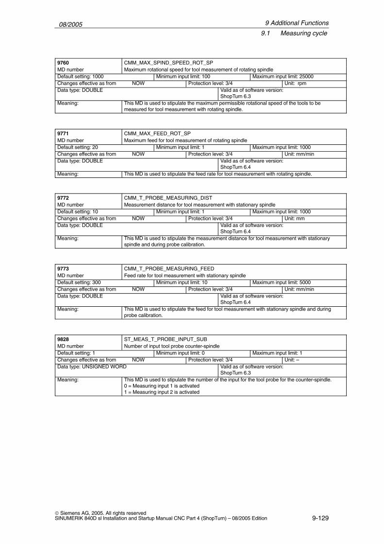
08/20059.1 Measuring cycle
9-129 Siemens AG, 2005. All rights reservedSINUMERIK 840D sl Installation and Startup Manual CNC Part 4 (ShopTurn) – 08/2005 Edition
ÁÁÁÁÁÁÁÁÁÁÁÁÁÁÁÁ
9760ÁÁÁÁÁÁÁÁÁÁÁÁÁÁÁÁÁÁÁÁÁÁÁÁÁÁÁÁÁÁÁÁÁÁÁÁÁÁÁÁÁÁÁÁÁÁ
CMM_MAX_SPIND_SPEED_ROT_SPÁÁÁÁÁÁÁÁÁÁÁÁÁÁÁÁ
MD number ÁÁÁÁÁÁÁÁÁÁÁÁÁÁÁÁÁÁÁÁÁÁÁÁÁÁÁÁÁÁÁÁÁÁÁÁÁÁÁÁÁÁÁÁÁÁ
Maximum rotational speed for tool measurement of rotating spindle
ÁÁÁÁÁÁÁÁÁÁÁÁÁÁÁÁÁÁÁÁÁÁ
Default setting: 1000 ÁÁÁÁÁÁÁÁÁÁÁÁÁÁÁÁÁÁÁÁÁÁ
Minimum input limit: 100 ÁÁÁÁÁÁÁÁÁÁÁÁÁÁÁÁÁÁÁÁ
Maximum input limit: 25000
ÁÁÁÁÁÁÁÁÁÁÁÁÁÁChanges effective as from NOW ÁÁÁÁÁÁÁÁÁÁÁProtection level: 3/4 ÁÁÁÁÁÁÁUnit: rpmÁÁÁÁÁÁÁÁÁÁÁÁÁÁÁÁÁÁÁÁÁÁÁÁÁÁÁÁÁÁÁÁÁÁÁÁÁÁÁÁÁÁÁÁÁÁÁÁÁÁÁ
Data type: DOUBLE ÁÁÁÁÁÁÁÁÁÁÁÁÁÁÁÁÁÁÁÁÁÁÁÁÁÁÁÁÁÁÁÁÁÁÁÁÁÁÁÁÁÁ
Valid as of software version:ShopTurn 6.3
ÁÁÁÁÁÁÁÁÁÁÁÁÁÁÁÁ
Meaning: ÁÁÁÁÁÁÁÁÁÁÁÁÁÁÁÁÁÁÁÁÁÁÁÁÁÁÁÁÁÁÁÁÁÁÁÁÁÁÁÁÁÁÁÁÁÁ
This MD is used to stipulate the maximum permissible rotational speed of the tools to bemeasured for tool measurement with rotating spindle.
ÁÁÁÁÁÁÁÁÁÁÁÁÁÁÁÁ9771
ÁÁÁÁÁÁÁÁÁÁÁÁÁÁÁÁÁÁÁÁÁÁÁÁÁÁÁÁÁÁÁÁÁÁÁÁÁÁÁÁÁÁÁÁÁÁCMM_MAX_FEED_ROT_SPÁÁÁÁÁÁÁÁ
ÁÁÁÁÁÁÁÁMD number
ÁÁÁÁÁÁÁÁÁÁÁÁÁÁÁÁÁÁÁÁÁÁÁÁÁÁÁÁÁÁÁÁÁÁÁÁÁÁÁÁÁÁÁÁÁÁ
Maximum feed for tool measurement of rotating spindleÁÁÁÁÁÁÁÁÁÁÁÁÁÁÁÁÁÁÁÁÁÁ
Default setting: 20 ÁÁÁÁÁÁÁÁÁÁÁÁÁÁÁÁÁÁÁÁÁÁ
Minimum input limit: 1 ÁÁÁÁÁÁÁÁÁÁÁÁÁÁÁÁÁÁÁÁ
Maximum input limit: 1000
ÁÁÁÁÁÁÁÁÁÁÁÁÁÁChanges effective as from NOW ÁÁÁÁÁÁÁÁÁÁÁProtection level: 3/4 ÁÁÁÁÁÁÁUnit: mm/minÁÁÁÁÁÁÁÁÁÁÁÁÁÁÁÁÁÁÁÁÁÁÁÁÁÁÁÁÁÁÁÁÁÁÁÁÁÁÁÁÁÁÁÁÁÁÁÁÁÁÁ
Data type: DOUBLEÁÁÁÁÁÁÁÁÁÁÁÁÁÁÁÁÁÁÁÁÁÁÁÁÁÁÁÁÁÁÁÁÁÁÁÁÁÁÁÁÁÁ
Valid as of software version:ShopTurn 6.4
ÁÁÁÁÁÁÁÁMeaning: ÁÁÁÁÁÁÁÁÁÁÁÁÁÁÁÁÁÁÁÁÁÁÁThis MD is used to stipulate the feed rate for tool measurement with rotating spindle.
ÁÁÁÁÁÁÁÁÁÁÁÁÁÁÁÁ
9772 ÁÁÁÁÁÁÁÁÁÁÁÁÁÁÁÁÁÁÁÁÁÁÁÁÁÁÁÁÁÁÁÁÁÁÁÁÁÁÁÁÁÁÁÁÁÁ
CMM_T_PROBE_MEASURING_DIST
ÁÁÁÁÁÁÁÁÁÁÁÁÁÁÁÁ
MD number ÁÁÁÁÁÁÁÁÁÁÁÁÁÁÁÁÁÁÁÁÁÁÁÁÁÁÁÁÁÁÁÁÁÁÁÁÁÁÁÁÁÁÁÁÁÁ
Measurement distance for tool measurement with stationary spindle
ÁÁÁÁÁÁÁÁÁÁÁDefault setting: 10
ÁÁÁÁÁÁÁÁÁÁÁMinimum input limit: 1
ÁÁÁÁÁÁÁÁÁÁMaximum input limit: 1000
ÁÁÁÁÁÁÁÁÁÁÁÁÁÁÁÁÁÁÁÁÁÁÁÁÁÁÁÁ
Changes effective as from NOW ÁÁÁÁÁÁÁÁÁÁÁÁÁÁÁÁÁÁÁÁÁÁ
Protection level: 3/4 ÁÁÁÁÁÁÁÁÁÁÁÁÁÁ
Unit: mm
ÁÁÁÁÁÁÁÁÁÁÁÁÁÁÁÁÁÁÁÁÁÁÁÁÁÁÁÁÁÁÁÁÁÁ
Data type: DOUBLE ÁÁÁÁÁÁÁÁÁÁÁÁÁÁÁÁÁÁÁÁÁÁÁÁÁÁÁÁ
Valid as of software version:ShopTurn 6.4
ÁÁÁÁÁÁÁÁÁÁÁÁÁÁÁÁÁÁÁÁÁÁÁÁ
Meaning: ÁÁÁÁÁÁÁÁÁÁÁÁÁÁÁÁÁÁÁÁÁÁÁÁÁÁÁÁÁÁÁÁÁÁÁÁÁÁÁÁÁÁÁÁÁÁÁÁÁÁÁÁÁÁÁÁÁÁÁÁÁÁÁÁÁÁÁÁÁ
This MD is used to stipulate the measurement distance for tool measurement with stationaryspindle and during probe calibration.
ÁÁÁÁÁÁÁÁÁÁÁÁÁÁÁÁ
9773 ÁÁÁÁÁÁÁÁÁÁÁÁÁÁÁÁÁÁÁÁÁÁÁÁÁÁÁÁÁÁÁÁÁÁÁÁÁÁÁÁÁÁÁÁÁÁ
CMM_T_PROBE_MEASURING_FEED
ÁÁÁÁÁÁÁÁÁÁÁÁÁÁÁÁ
MD number ÁÁÁÁÁÁÁÁÁÁÁÁÁÁÁÁÁÁÁÁÁÁÁÁÁÁÁÁÁÁÁÁÁÁÁÁÁÁÁÁÁÁÁÁÁÁ
Feed rate for tool measurement with stationary spindle
ÁÁÁÁÁÁÁÁÁÁÁDefault setting: 300 ÁÁÁÁÁÁÁÁÁÁÁMinimum input limit: 10 ÁÁÁÁÁÁÁÁÁÁMaximum input limit: 5000ÁÁÁÁÁÁÁÁÁÁÁÁÁÁÁÁÁÁÁÁÁÁÁÁÁÁÁÁ
Changes effective as from NOW ÁÁÁÁÁÁÁÁÁÁÁÁÁÁÁÁÁÁÁÁÁÁ
Protection level: 3/4 ÁÁÁÁÁÁÁÁÁÁÁÁÁÁ
Unit: mm/minÁÁÁÁÁÁÁÁÁÁÁÁÁÁÁÁÁÁÁÁÁÁÁÁÁÁÁÁÁÁÁÁÁÁ
Data type: DOUBLE ÁÁÁÁÁÁÁÁÁÁÁÁÁÁÁÁÁÁÁÁÁÁÁÁÁÁÁÁ
Valid as of software version:ShopTurn 6.4ÁÁÁÁÁÁÁÁ
ÁÁÁÁÁÁÁÁÁÁÁÁÁÁÁÁ
Meaning: ÁÁÁÁÁÁÁÁÁÁÁÁÁÁÁÁÁÁÁÁÁÁÁÁÁÁÁÁÁÁÁÁÁÁÁÁÁÁÁÁÁÁÁÁÁÁÁÁÁÁÁÁÁÁÁÁÁÁÁÁÁÁÁÁÁÁÁÁÁ
This MD is used to stipulate the feed for tool measurement with stationary spindle and duringprobe calibration.
ÁÁÁÁÁÁÁÁÁÁÁÁÁÁÁÁ
9828ÁÁÁÁÁÁÁÁÁÁÁÁÁÁÁÁÁÁÁÁÁÁÁÁÁÁÁÁÁÁÁÁÁÁÁÁÁÁÁÁÁÁÁÁÁÁ
ST_MEAS_T_PROBE_INPUT_SUBÁÁÁÁÁÁÁÁÁÁÁÁÁÁÁÁ
MD number ÁÁÁÁÁÁÁÁÁÁÁÁÁÁÁÁÁÁÁÁÁÁÁÁÁÁÁÁÁÁÁÁÁÁÁÁÁÁÁÁÁÁÁÁÁÁ
Number of input tool probe counter-spindle
ÁÁÁÁÁÁÁÁÁÁÁDefault setting: 1 ÁÁÁÁÁÁÁÁÁÁÁMinimum input limit: 0 ÁÁÁÁÁÁÁÁÁÁMaximum input limit: 1ÁÁÁÁÁÁÁÁÁÁÁÁÁÁÁÁÁÁÁÁÁÁÁÁÁÁÁÁ
Changes effective as from NOWÁÁÁÁÁÁÁÁÁÁÁÁÁÁÁÁÁÁÁÁÁÁ
Protection level: 3/4ÁÁÁÁÁÁÁÁÁÁÁÁÁÁ
Unit: –ÁÁÁÁÁÁÁÁÁÁÁÁÁÁÁÁÁÁÁÁÁÁÁÁÁÁÁÁÁÁÁÁÁÁ
Data type: UNSIGNED WORD ÁÁÁÁÁÁÁÁÁÁÁÁÁÁÁÁÁÁÁÁÁÁÁÁÁÁÁÁ
Valid as of software version:ShopTurn 6.3ÁÁÁÁÁÁÁÁ
ÁÁÁÁÁÁÁÁÁÁÁÁÁÁÁÁ
Meaning:ÁÁÁÁÁÁÁÁÁÁÁÁÁÁÁÁÁÁÁÁÁÁÁÁÁÁÁÁÁÁÁÁÁÁÁÁÁÁÁÁÁÁÁÁÁÁÁÁÁÁÁÁÁÁÁÁÁÁÁÁÁÁÁÁÁÁÁÁÁ
This MD is used to stipulate the number of the input for the tool probe for the counter-spindle.0 = Measuring input 1 is activated1 = Measuring input 2 is activated
9 Additional Functions

08/20059.2 Network link
9-130 Siemens AG, 2005. All rights reserved
SINUMERIK 840D sl Installation and Startup Manual CNC Part 4 (ShopTurn) – 08/2005 Edition
9.2 Network link
The function “Manage up to 4 additional network drives” is an option with ordernumber 6FC5 800-0AP01-0YB0.
For installing the network, please refer to
References: /IAM/, Commissioning Manual CNC Part 2 (HMI)SINUMERIK 840D sl/840D/840Di/810D,
IM2, Commissioning HMI Embedded (sl)IM4, Commissioning HMI Advanced
Option
9 Additional Functions

08/20059.3 Cylinder surface transformation, end face machining
9-131 Siemens AG, 2005. All rights reservedSINUMERIK 840D sl Installation and Startup Manual CNC Part 4 (ShopTurn) – 08/2005 Edition
9.3 Cylinder surface transformation, end face machining
9.3.1 General information
The cylinder surface transformation and end face machining functions can beused to machine the peripheral and end faces of a turned part.
The functions “cylinder surface transformation” (Tracyl) and “face end machin-ing” (Transmit) are a software option set on the CNC-ISO operator interface.The order no. is: 6FC5 800-0AM27-0YB0.
These functions must also be set up via machine data.
� Face-end machining main spindle: Transformation 1MD 24100 $MC_TRAFO_TYPE_1=256 (without Y axis)MD 24100 $MC_TRAFO_TYPE_1=257 (with Y axis)
� Face-end machining counter-spindle: Transformation 2MD 24200 $MC_TRAFO_TYPE_2=256 (without Y axis)MD 24200 $MC_TRAFO_TYPE_1=257 (with Y axis)
� Cylinder surface transformation main spindle: Transformation 3without groove side offset (without Y axis):MD 24300 $MC_TRAFO_TYPE_3=512with groove side offset (with Y axis):MD 24300 $MC_TRAFO_TYPE_3=513with groove side offset and Y correction:MD 24300 $MC_TRAFO_TYPE_3=514
� Cylinder surface transformation counter-spindle: Transformation 4without groove side offset (without Y axis):MD 24400 $MC_TRAFO_TYPE_4=512with groove side offset (with Y axis):MD 24400 $MC_TRAFO_TYPE_4=513with groove side offset and Y correction:MD 24400 $MC_TRAFO_TYPE_4=514
Note
For each of the individual transformations you must also set up other machinedata (see following Sections).
The “cylinder surface transformation” and “end face machining” functions areautomatically integrated in the ShopTurn cycles, with the exception of “straightline” and “circle”. For these two cycles you can call the functions in the operatingarea - Program under Straight line, Arc, Tool.References: /BAT/, ShopTurn Operating / Programming Guide
9 Additional Functions

08/20059.3 Cylinder surface transformation, end face machining
9-132 Siemens AG, 2005. All rights reserved
SINUMERIK 840D sl Installation and Startup Manual CNC Part 4 (ShopTurn) – 08/2005 Edition
9.3.2 Example: X axis and Z axis, main spindle and tool spindle
For example, for a turning machine with X and Z axes, main spindle (C1) andtool spindle (WZ) you must configure the following machine data:
2008020080 $MC_AXCONF_CHANAX_NAME_TAB[0]=“XC”Channel axis XC
20080 $MC_AXCONF_CHANAX_NAME_TAB[1]=“ZC”Channel axis ZC
20080 $MC_AXCONF_CHANAX_NAME_TAB[2]=“C1”Channel axis C1
20080 $MC_AXCONF_CHANAX_NAME_TAB[3]=“WZ”Channel axis WZ
General settings for transformations:10602 $MN_FRAME_GEOAX_CHANGE_MODE=1When switching between geometric axes take account of coordinate trans-formations in total frame24040 $MC_FRAME_ADAPT_MODE=H7Adaptation of active frames28082 $MC_MM_SYSTEM_FRAME_MASK, Bit 6=1Projecting channel-specific system frames included in channel calculation
Data set for face end machining (main spindle):24100 $MC_TRAFO_TYPE_1=256
Definition of 1st transformation in channel: TRANSMIT main spindle
24110 $MC_TRAFO_AXES_IN_1[0]=1Channel axis perpendicular to rotary axis (XC) for 1st transformation
24110 $MC_TRAFO_AXES_IN_1[1]=3Channel axis of rotary axis (C1) for 1st transformation
24110 $MC_TRAFO_AXES_IN_1[2]=2Channel axis parallel to rotary axis (ZC) for 1st transformation
24120 $MC_TRAFO_GEOAX_ASSIGN_TAB_1[0]=11st channel axis (X) for 1st transformation
24120 $MC_TRAFO_GEOAX_ASSIGN_TAB_1[1]=32nd channel axis (Y) for 1st transformation
24120 $MC_TRAFO_GEOAX_ASSIGN_TAB_1[2]=23rd channel axis (Z) for 1st transformation
24900 $MC_TRANSMIT_ROT_AX_OFFSET_1=0Offset of rotary axis for 1st TRANSMIT transformation
24905 $MC_TRANSMIT_ROT_AX_FRAME_1=2Axial offset of rotary axis is taken into account during TRANSMIT
24910 $MC_TRANSMIT_ROT_SIGN_IS_PLUS_1=0Arithmetic sign of rotary axis for 1st TRANSMIT transformation
24911 $MC_TRANSMIT_POLE_SIDE_FIX_1=1Restriction of working area in front of / behind pole,1st TRANSMIT transformation
24920 $MC_TRANSMIT_BASE_TOOL_1[0]=0Vector of basic tool for 1st TRANSMIT transformation
Face end machining
9 Additional Functions

08/20059.3 Cylinder surface transformation, end face machining
9-133 Siemens AG, 2005. All rights reservedSINUMERIK 840D sl Installation and Startup Manual CNC Part 4 (ShopTurn) – 08/2005 Edition
Data set for cylinder surface transformation without groove side offset (mainspindle):24300 $MC_TRAFO_TYPE_3=512
Definition of 3rd transformation in channel: TRACYL main spindle24310 $MC_TRAFO_AXES_IN_3[0]=1
Channel axis perpendicular to rotary axis (XC) for 3rd transformation
24310 $MC_TRAFO_AXES_IN_3[1]=3Channel axis of rotary axis (C1) for 3rd transformation
24310 $MC_TRAFO_AXES_IN_3[2]=2Channel axis parallel to rotary axis (ZC) for 3rd transformation
24320 $MC_TRAFO_GEOAX_ASSIGN_TAB_3[0]=11st channel axis (X) for 3rd transformation
24320 $MC_TRAFO_GEOAX_ASSIGN_TAB_3[1]=32nd channel axis (Y) for 3rd transformation
24320 $MC_TRAFO_GEOAX_ASSIGN_TAB_3[2]=23rd channel axis (Z) for 3rd transformation
24800 $MC_TRACYL_ROT_AX_OFFSET_1=0Offset of rotary axis for 1st TRACYL transformation
24805 $MC_TRACYL_ROT_AX_FRAME_1=2Axial offset of rotary axis is taken into account during TRACYL
24810 $MC_TRACYL_ROT_SIGN_IS_PLUS_1=1Arithmetic sign of rotary axis for 1st TRACYL transformation
24820 $MC_TRACYL_BASE_TOOL_1[n]=0Vector of basic tool for 1st TRACYL transformation
Cylinder surfacetransformationwithout grooveside offset
9 Additional Functions

08/20059.3 Cylinder surface transformation, end face machining
9-134 Siemens AG, 2005. All rights reserved
SINUMERIK 840D sl Installation and Startup Manual CNC Part 4 (ShopTurn) – 08/2005 Edition
9.3.3 Example: X axis and Z axis, main spindle and tool spindle, Y axis
For example, for a turning machine with X, Z, and Y axes, main spindle (C1)and tool spindle (WZ) you must configure the following machine data:
2008020080 $MC_AXCONF_CHANAX_NAME_TAB[0]=“XC”Channel axis XC
20080 $MC_AXCONF_CHANAX_NAME_TAB[1]=“ZC”Channel axis ZC
20080 $MC_AXCONF_CHANAX_NAME_TAB[2]=“C1”Channel axis C1
20080 $MC_AXCONF_CHANAX_NAME_TAB[3]=“WZ”Channel axis WZ
20080 $MC_AXCONF_CHANAX_NAME_TAB[5]=“YC”Channel axis YC
General settings for transformations:10602 $MN_FRAME_GEOAX_CHANGE_MODE=1When switching between geometric axes take account of coordinate trans-formations in total frame24040 $MC_FRAME_ADAPT_MODE=H7Adaptation of active frames28082 $MC_MM_SYSTEM_FRAME_MASK, Bit 6=1Projecting channel-specific system frames included in channel calculation
Data set for face end machining (main spindle):24100 $MC_TRAFO_TYPE_1=257
Definition of 1st transformation in channel: TRANSMIT main spindle
24110 $MC_TRAFO_AXES_IN_1[0]=1Channel axis perpendicular to rotary axis (XC) for 1st transformation
24110 $MC_TRAFO_AXES_IN_1[1]=3Channel axis of rotary axis (C1) for 1st transformation
24110 $MC_TRAFO_AXES_IN_1[2]=2Channel axis parallel to rotary axis (ZC) for 1st transformation
24120 $MC_TRAFO_GEOAX_ASSIGN_TAB_1[0]=11st channel axis (X) for 1st transformation
24120 $MC_TRAFO_GEOAX_ASSIGN_TAB_1[1]=32nd channel axis (Y) for 1st transformation
24120 $MC_TRAFO_GEOAX_ASSIGN_TAB_1[2]=23rd channel axis (Z) for 1st transformation
24900 $MC_TRANSMIT_ROT_AX_OFFSET_1=0Offset of rotary axis for 1st TRANSMIT transformation
24905 $MC_TRANSMIT_ROT_AX_FRAME_1=2Axial offset of rotary axis is taken into account during TRANSMIT
24910 $MC_TRANSMIT_ROT_SIGN_IS_PLUS_1=0Arithmetic sign of rotary axis for 1st TRANSMIT transformation
24911 $MC_TRANSMIT_POLE_SIDE_FIX_1=1Restriction of working area in front of / behind pole,1st TRANSMIT transformation
24920 $MC_TRANSMIT_BASE_TOOL_1[0]=0Vector of basic tool for 1st TRANSMIT transformation
Face end machining
9 Additional Functions

08/20059.3 Cylinder surface transformation, end face machining
9-135 Siemens AG, 2005. All rights reservedSINUMERIK 840D sl Installation and Startup Manual CNC Part 4 (ShopTurn) – 08/2005 Edition
Data set for cylinder surface transformation with groove side offset (mainspindle):24300 $MC_TRAFO_TYPE_3=513
Definition of 3rd transformation in channel: TRACYL main spindle24310 $MC_TRAFO_AXES_IN_3[0]=1
Channel axis perpendicular to rotary axis (XC) for 3rd transformation
24310 $MC_TRAFO_AXES_IN_3[1]=3Channel axis of rotary axis (C1) for 3rd transformation
24310 $MC_TRAFO_AXES_IN_3[2]=2Channel axis parallel to rotary axis (ZC) for 3rd transformation
24310 $MC_TRAFO_AXES_IN_3[3]=6Channel axis parallel to cylinder peripheral surface and perpendicular to rotary axis (ZC) for 3rd transformation
24320 $MC_TRAFO_GEOAX_ASSIGN_TAB_3[0]=11st channel axis (X) for 3rd transformation
24320 $MC_TRAFO_GEOAX_ASSIGN_TAB_3[1]=32nd channel axis (Y) for 3rd transformation
24320 $MC_TRAFO_GEOAX_ASSIGN_TAB_3[2]=23rd channel axis (Z) for 3rd transformation
24800 $MC_TRACYL_ROT_AX_OFFSET_1=0Offset of rotary axis for 1st TRACYL transformation
24805 $MC_TRACYL_ROT_AX_FRAME_1=2Axial offset of rotary axis is taken into account during TRACYL
24810 $MC_TRACYL_ROT_SIGN_IS_PLUS_1=1Arithmetic sign of rotary axis for 1st TRACYL transformation
24820 $MC_TRACYL_BASE_TOOL_1[n]=0Vector of basic tool for 1st TRACYL transformation
Cylinder surfacetransformationwith groove sideoffset
9 Additional Functions

08/20059.3 Cylinder surface transformation, end face machining
9-136 Siemens AG, 2005. All rights reserved
SINUMERIK 840D sl Installation and Startup Manual CNC Part 4 (ShopTurn) – 08/2005 Edition
9.3.4 Example: X axis and Z axis, main spindle, tool spindle andcounter-spindle
For example, for a turning machine with X and Z axes, main spindle (C1), toolspindle (WZ), and counter-spindle (C2) you must configure the following ma-chine data:
2008020080 $MC_AXCONF_CHANAX_NAME_TAB[0]=“XC”Channel axis XC
20080 $MC_AXCONF_CHANAX_NAME_TAB[1]=“ZC”Channel axis ZC
20080 $MC_AXCONF_CHANAX_NAME_TAB[2]=“C1”Channel axis C1
20080 $MC_AXCONF_CHANAX_NAME_TAB[3]=“WZ”Channel axis WZ
20080 $MC_AXCONF_CHANAX_NAME_TAB[4]=“C2”Channel axis C2
General settings for transformations:10602 $MN_FRAME_GEOAX_CHANGE_MODE=1When switching between geometric axes take account of coordinate trans-formations in total frame24040 $MC_FRAME_ADAPT_MODE=H7Adaptation of active frames28082 $MC_MM_SYSTEM_FRAME_MASK, Bit 6=1Projecting channel-specific system frames included in channel calculation
Data set for face end machining (counter-spindle):24200 $MC_TRAFO_TYPE_2=256
Definition of 2nd transformation in channel: TRANSMIT counter-spindle
24210 $MC_TRAFO_AXES_IN_2[0]=1Channel axis perpendicular to rotary axis (XC) for 2nd transformation
24210 $MC_TRAFO_AXES_IN_2[1]=5Channel axis of rotary axis (C2) for 2nd transformation
24210 $MC_TRAFO_AXES_IN_2[2]=2Channel axis parallel to rotary axis (ZC) for 2nd transformation
24220 $MC_TRAFO_GEOAX_ASSIGN_TAB_2[0]=11st channel axis (X) for 2nd transformation
24220 $MC_TRAFO_GEOAX_ASSIGN_TAB_2[1]=52nd channel axis (Y) for 2nd transformation
24220 $MC_TRAFO_GEOAX_ASSIGN_TAB_2[2]=23rd channel axis (Z) for 2nd transformation
24950 $MC_TRANSMIT_ROT_AX_offset_2=0Offset of rotary axis for 2nd TRANSMIT transformation
24955 $MC_TRANSMIT_ROT_AX_FRAME_2=2Axial offset of rotary axis is taken into account during TRANSMIT
24960 $MC_TRANSMIT_ROT_SIGN_IS_PLUS_2=0Arithmetic sign of rotary axis for 2nd TRANSMIT transformation
24961 $MC_TRANSMIT_POLE_SIDE_FIX_2=1Restriction of operating area in front of / behind the pole,2nd TRANSMIT transformation
24970 $MC_TRANSMIT_BASE_TOOL_2[0]=0Vector of basic tool for 2nd TRANSMIT transformation
Face end machining
9 Additional Functions

08/20059.3 Cylinder surface transformation, end face machining
9-137 Siemens AG, 2005. All rights reservedSINUMERIK 840D sl Installation and Startup Manual CNC Part 4 (ShopTurn) – 08/2005 Edition
Data set for cylinder surface transformation on counter-spindle (without grooveside offset):24400 $MC_TRAFO_TYPE_4=512
Definition of 4th transformation in channel: TRACYL counter-spindle
24410 $MC_TRAFO_AXES_IN_4[0]=1Channel axis perpendicular to rotary axis (XC) for 4th transformation
24410 $MC_TRAFO_AXES_IN_4[1]=5Channel axis of rotary axis (C2) for 4th transformation
24410 $MC_TRAFO_AXES_IN_4[2]=2Channel axis parallel to rotary axis (ZC) for 4th transformation
24420 $MC_TRAFO_GEOAX_ASSIGN_TAB_4[0]=11st channel axis (X) for 4th transformation
24420 $MC_TRAFO_GEOAX_ASSIGN_TAB_4[1]=52nd channel axis (Y) for 4th transformation
24420 $MC_TRAFO_GEOAX_ASSIGN_TAB_4[2]=23rd channel axis (Z) for 4th transformation
24850 $MC_TRACYL_ROT_AX_offset_2=0Offset of rotary axis for 2nd TRACYL transformation
24855 $MC_TRACYL_ROT_AX_FRAME_2=2Axial offset of rotary axis is taken into account during TRACYL
24860 $MC_TRACYL_ROT_SIGN_IS_PLUS_2=1Arithmetic sign of rotary axis for 2nd TRACYL transformation
24870 $MC_TRACYL_BASE_TOOL_2[n]=0Vector of basic tool for 2nd TRACYL transformation
Cylinder surfacetransformationwithout grooveside offset
9 Additional Functions

08/20059.3 Cylinder surface transformation, end face machining
9-138 Siemens AG, 2005. All rights reserved
SINUMERIK 840D sl Installation and Startup Manual CNC Part 4 (ShopTurn) – 08/2005 Edition
9.3.5 Example: X axis and Z axis, main spindle, tool spindle, andcounter-spindle, Y axis
For example, for a turning machine with X, Z, and Y axes, main spindle (C1),tool spindle (WZ), and counter-spindle (C2) you must configure the followingmachine data:
20080 $MC_AXCONF_CHANAX_NAME_TAB[0]=“XC”Channel axis XC
20080 $MC_AXCONF_CHANAX_NAME_TAB[1]=“ZC”Channel axis ZC
20080 $MC_AXCONF_CHANAX_NAME_TAB[2]=“C1”Channel axis C1
20080 $MC_AXCONF_CHANAX_NAME_TAB[3]=“WZ”Channel axis WZ
20080 $MC_AXCONF_CHANAX_NAME_TAB[4]=“C2”Channel axis C2
20080 $MC_AXCONF_CHANAX_NAME_TAB[5]=“YC”Channel axis YC
General settings for transformations:10602 $MN_FRAME_GEOAX_CHANGE_MODE=1When switching between geometric axes take account of coordinate trans-formations in total frame24040 $MC_FRAME_ADAPT_MODE=H7Adaptation of active frames28082 $MC_MM_SYSTEM_FRAME_MASK, Bit 6=1Projecting channel-specific system frames included in channel calculation
9 Additional Functions

08/20059.3 Cylinder surface transformation, end face machining
9-139 Siemens AG, 2005. All rights reservedSINUMERIK 840D sl Installation and Startup Manual CNC Part 4 (ShopTurn) – 08/2005 Edition
Data set for face end machining (counter-spindle):24200 $MC_TRAFO_TYPE_2=257
Definition of 2nd transformation in channel: TRANSMIT counter-spindle
24210 $MC_TRAFO_AXES_IN_2[0]=1Channel axis perpendicular to rotary axis (XC) for 2nd transformation
24210 $MC_TRAFO_AXES_IN_2[1]=5Channel axis of rotary axis (C2) for 2nd transformation
24210 $MC_TRAFO_AXES_IN_2[2]=2Channel axis parallel to rotary axis (ZC) for 2nd transformation
24220 $MC_TRAFO_GEOAX_ASSIGN_TAB_2[0]=11st channel axis (X) for 2nd transformation
24220 $MC_TRAFO_GEOAX_ASSIGN_TAB_2[1]=52nd channel axis (Y) for 2nd transformation
24220 $MC_TRAFO_GEOAX_ASSIGN_TAB_2[2]=23rd channel axis (Z) for 2nd transformation
24950 $MC_TRANSMIT_ROT_AX_offset_2=0Offset of rotary axis for 2nd TRANSMIT transformation
24955 $MC_TRANSMIT_ROT_AX_FRAME_2=2Axial offset of rotary axis is taken into account during TRANSMIT
24960 $MC_TRANSMIT_ROT_SIGN_IS_PLUS_2=0Arithmetic sign of rotary axis for 2nd TRANSMIT transformation
24961 $MC_TRANSMIT_POLE_SIDE_FIX_2=1Restriction of operating area in front of / behind the pole,2nd TRANSMIT transformation
24970 $MC_TRANSMIT_BASE_TOOL_2[0]=0Vector of basic tool for 2nd TRANSMIT transformation
Data set for cylinder surface transformation with groove side offset (counter-spindle):24400 $MC_TRAFO_TYPE_4=513
Definition of 4th transformation in channel: TRACYL counter-spindle
24410 $MC_TRAFO_AXES_IN_4[0]=1Channel axis perpendicular to rotary axis (XC) for 4th transformation
24410 $MC_TRAFO_AXES_IN_4[1]=5Channel axis of rotary axis (C2) for 4th transformation
24410 $MC_TRAFO_AXES_IN_4[2]=2Channel axis parallel to rotary axis (ZC) for 4th transformation
24410 $MC_TRAFO_AXES_IN_4[3]=6Channel axis parallel to cylinder peripheral surface and perpendicular to rotary axis (ZC) for 4th transformation
24420 $MC_TRAFO_GEOAX_ASSIGN_TAB_4[0]=11st channel axis (X) for 4th transformation
24420 $MC_TRAFO_GEOAX_ASSIGN_TAB_4[1]=52nd channel axis (Y) for 4th transformation
24420 $MC_TRAFO_GEOAX_ASSIGN_TAB_4[2]=23rd channel axis (Z) for 4th transformation
24850 $MC_TRACYL_ROT_AX_OFFSET_2=0Offset of rotary axis for 2nd TRACYL transformation
24855 $MC_TRACYL_ROT_AX_FRAME_2=2Axial offset of rotary axis is taken into account during TRACYL
24860 $MC_TRACYL_ROT_SIGN_IS_PLUS_2=1Arithmetic sign of rotary axis for 2nd TRACYL transformation
24870 $MC_TRACYL_BASE_TOOL_2[n]=0Vector of basic tool for 2nd TRACYL transformation
Face end machining
Cylinder surfacetransformationwith groove sideoffset
9 Additional Functions

08/20059.4 Inclined Y axis
9-140 Siemens AG, 2005. All rights reserved
SINUMERIK 840D sl Installation and Startup Manual CNC Part 4 (ShopTurn) – 08/2005 Edition
9.4 Inclined Y axis
If your machine has an inclined Y axis (i.e. the Y axis is not perpendicular to theother axes), you can still program the entire machining sequence in the Carte-sian coordinate system. The control uses the “Inclined axis” function (Traang) totransform the Cartesian coordinates to the traveling motions of the inclined axis.
The function “Inclined Axis” (Traang) is a software option which you need to setin the CNC-ISO user interface. The order no. is: 6FC5 800-0AM28-0YB0.
You also need to set up the “Inclined axis” function (Traang) in the machinedata.References: /FB2/, Description of Functions Extended Functions,
M1, Kinematic Transformations
Once the “Inclined axis” function has been set up in the ShopTurn user inter-face, it is automatically integrated in the ShopTurn cycles. This means you canselect machining level “Face Y” or “Surface Y” in the masks and enter the posi-tion for the inclined Y axis in Cartesian coordinates.References: /BAT/, ShopTurn Operating/Programming Guide
For example, for a turning machine with X and Z axes and inclined Y axis, mainspindle (C), and tool spindle (WZ) you must configure the following machinedata:
20050 $MC_AXCONF_GEOAX_ASSIGN_TAB[0]=11st real geometric axis (X axis)
20050 $MC_AXCONF_GEOAX_ASSIGN_TAB[1]=02nd real geometric axis (Y axis) not configured
20050 $MC_AXCONF_GEOAX_ASSIGN_TAB[2]=23rd real geometric axis (Z axis)
20110 $MC_RESET_MODE_MASK, Bit 0 = 1, Bit 7 = 0TRAANG retained after booting
20112 $MC_START_MODE_MASK, Bit 7 = 1TRAANG retained after “Cycle start”
20118 $MC_GEOAX_CHANGE_RESET=1Allow automatic switching of geometric axes
20140 $MC_TRAFO_RESET_VALUE=5 TRAANG is always active after reset
20144 $MC_TRAFO_MODE_MASK, bit 1 = 0 TRAANG runs in background (persistent process) and is not displayed in the operator interface
Example
9 Additional Functions

08/20059.4 Inclined Y axis
9-141 Siemens AG, 2005. All rights reservedSINUMERIK 840D sl Installation and Startup Manual CNC Part 4 (ShopTurn) – 08/2005 Edition
20070 $MC_AXCONF_MACHAX_USED[4]=5Channel axis YC = 5th machine axis
20080 $MC_AXCONF_CHANAX_NAME_TAB[0]=“XC”1st channel axis = XC
20080 $MC_AXCONF_CHANAX_NAME_TAB[1]=“ZC”2nd channel axis = ZC
20080 $MC_AXCONF_CHANAX_NAME_TAB[2]=“C”3rd channel axis = C
20080 $MC_AXCONF_CHANAX_NAME_TAB[3]=“WZ”4th channel axis = WZ
20080 $MC_AXCONF_CHANAX_NAME_TAB[4]=“YC”5th channel axis = YC
Data set for “Inclined axis”:24430 $MC_TRAFO_TYPE_5=1024
Transformation 5: TRAANG24432 $MC_TRAFO_AXES_IN_5[0]=5
1st transformation axis with transformation 5 = channel axis YC
24432 $MC_TRAFO_AXES_IN_5[1]=12nd transformation axis with transformation 5 = channel axis XC
24432 $MC_TRAFO_AXES_IN_5[2]=23rd transformation axis with transformation 5 = channel axis ZC
24434 $MC_TRAFO_GEOAX_ASSIGN_TAB_5[0]=11st geometric axis with transformation 5 = channel axis XC
24434 $MC_TRAFO_GEOAX_ASSIGN_TAB_5[1]=52nd geometric axis with transformation 5 = channel axis YC
24434 $MC_TRAFO_GEOAX_ASSIGN_TAB_5[2]=23rd geometric axis with transformation 5 = channel axis ZC
24436 $MC_TRAFO_INCLUDES_TOOL_5=0Tool included when 5th transformation is active
24700 $MC_TRAANG_ANGLE_1=55Angle between 1st and 2nd transformation axes
Data set for linking (TRACON) face end machining on main spindle (TRANS-MIT) and “Inclined axis” (TRAANG):24440 $MC_TRAFO_TYPE_6=8192
Transformation 6: TRACON24444 $MC_TRAFO_GEOAX_ASSIGN_TAB_6[0]=1
1st geometric axis with transformation 6 = channel axis XC24444 $MC_TRAFO_GEOAX_ASSIGN_TAB_6[1]=3
2nd geometric axis with transformation 6 = channel axis C24444 $MC_TRAFO_GEOAX_ASSIGN_TAB_6[2]=2
3rd geometric axis with transformation 6 = channel axis ZC24995 $MC_TRACON_CHAIN_1[0]=1
Number of transformation TRANSMIT (main spindle) for linking
24995 $MC_TRACON_CHAIN_1[1]=5Number of transformation TRAANG for linking
9 Additional Functions

08/20059.4 Inclined Y axis
9-142 Siemens AG, 2005. All rights reserved
SINUMERIK 840D sl Installation and Startup Manual CNC Part 4 (ShopTurn) – 08/2005 Edition
Data set for linking (TRACON) from cylinder surface transformation mainspindle and “Inclined axis” (TRAANG):24450 $MC_TRAFO_TYPE_7=8192
Transformation 7: TRACON24454 $MC_TRAFO_GEOAX_ASSIGN_TAB_6[0]=1
1st geometric axis with transformation 7 = channel axis XC24454 $MC_TRAFO_GEOAX_ASSIGN_TAB_6[1]=3
2nd geometric axis with transformation 7 = channel axis C24454 $MC_TRAFO_GEOAX_ASSIGN_TAB_6[2]=2
3rd geometric axis with transformation 7 = channel axis ZC24996 $MC_TRACON_CHAIN_1[0]=1
Number of transformation TRACYL (main spindle) for linking24996 $MC_TRACON_CHAIN_1[3]=5
Number of transformation TRAANG for linking
9 Additional Functions
08/20059.5 Measuring cycle support in the G code editor
9-143 Siemens AG, 2005. All rights reservedSINUMERIK 840D sl Installation and Startup Manual CNC Part 4 (ShopTurn) – 08/2005 Edition
9.5 Measuring cycle support in the G code editor
In ShopTurn you can integrate screen forms which provide support for program-ming measuring cycles into the G code editor. These cycles can then be recom-piled automatically.
The “measuring cycles” function is a software option with order no. 6FC5 800-0AP28-0YB0.
For more information on measuring cycle support please refer to:References: /BNM/, Measuring Cycles User Manual
For start-up proceed as follows:
� Remove the semicolon “;” preceding the following lines in file STANDARD_CYCLES\COMMON.COM:;sc8406=aeditor.com ;Measuring cycles for turning (horizontal
;softkey 6 on the expanded softkey menu in ;the G code editor)
;sc8407=aeditor.com ;Measuring cycles for milling (horizontal ;softkey 7 on the expanded softkey menu in ;the G code editor)
By doing this, you create the connection between the softkeys used to callthe measuring cycles support and the configuration file of the supportscreens.
� Remove the semicolon “;” preceding the following line in file STAN-DARD_CYCLES\COMMON.COM:;sc617=startup.com ;Start-up operating area (horizontal
;softkey 7 on the expanded softkey bar)You can modify the characteristics of the measuring cycle support in thestart-up operating area.
� Restart the machine.
� If required, modify the characteristics for the measuring cycle support in the“Start-up” → “>” → “Measuring cycles” menu.
ShopTurn on NCU(HMI embedded)
9 Additional Functions

08/20059.5 Measuring cycle support in the G code editor
9-144 Siemens AG, 2005. All rights reserved
SINUMERIK 840D sl Installation and Startup Manual CNC Part 4 (ShopTurn) – 08/2005 Edition
Requirements:When HMI Advanced started up, the files AEDITOR.COM and STARTUP.COMmust have been stored in the STANDARD CYCLES (CST.DIR) directory.when ShopTurn started up the archive ST_CYC.ARC must have been trans-ferred fromthe PCU 50.3 to the NCK. The COMMON.COM file must have been copied au-tomatically to the STANDARD_CYCLES (CST.DIR) directory.
� Copy the archive MCSUPP from the ARCHIVES\CYCLES-ARCHIVE\MCYC.
� If you want to use the measurement result displays, you need to copy theMCRESULT archive from the ARCHIVES\CYCLE_ARCHIVES\MCYC direc-tory.
� If the versions of the standard measuring cycles supplied with ShopTurn (see file SIEMENSD.RTF or SIEMENSE.RTF on the software CD) differ from the HMI Advanced measuring cycles (see ARCHIVES\CY-CLE_ARCHIVES\MCYC\VERSION.ARC) in the first 4 digits (e.g. 06.02), you need to copy the archive MCYCTURN from the ARCHIVES\CYCLE_ARCHIVES\MCYC directory.
� Remove the semicolon “;” preceding the following lines in file STANDARD_CYCLES\COMMON.COM:;sc8406=aeditor.com ;Measuring cycles for turning (horizontal
;softkey 6 on the expanded softkey menu in ;the G code editor)
;sc8407=aeditor.com; ;Measuring cycles for milling (horizontal ;softkey 7 on the expanded softkey menu in ;the G code editor)
Remove the semicolon “;” preceding the following lines in the file STAN-DARD_CYCLES\AEDITOR.COM:;HS15=($83531,,se1);PRESS(HS15); LS(“F_mess”,”MZ_SKL.COM”,1);END_PRESS
By doing this, you create the connection between the softkeys used to callthe measuring cycles support and the configuration file of the supportscreens.
� In the file STANDARD_CYCLES\STARTUP.COM remove the semicolon “;”preceding the following lines:;HS15=($83070,,se1);PRESS(HS15); LS(”Messz”);END_PRESSThis allows you to modify the characteristics of the measuring cycle supportin the Start-up operating area.
� Restart the PCU 50.3.
� If required, modify the characteristics for the measuring cycle support in the“Start-up” → “>” → “Measuring cycles” menu.
PCU 50.3
9 Additional Functions

08/20059.6 Counter-spindle
9-145 Siemens AG, 2005. All rights reservedSINUMERIK 840D sl Installation and Startup Manual CNC Part 4 (ShopTurn) – 08/2005 Edition
9.6 Counter-spindle
If your turning machine has a counter-spindle, you can machine workpieceswith turning, drilling, and milling functions on the front and reverse side withouthaving to recheck the workpiece manually.
Before machining the reverse side, the counter-spindle must grip the workpiece,pull it out of the main spindle, and position it at the new machining position.
In order to use the counter-spindle on your machine, you need the software options “travel to fixed stop” (order no. 6FC5 800-0AM01-0YB0) and “synchronous spindle” (order no. 6FC5 800-0AM14-0YB0).
When setting up the counter-spindle you need to take the following machinedata into account:9803 $MM_ST_INDEX_AXIS_4: Axis index slide counter-spindle9806 $MM_ST_INDEX_SPINDLE_SUB: Axis index counter-spindle9812 $MM_ST_GEAR_STEPS_SPINDLE_SUB: Gear steps counter-spindle9823 $MM_ST_DISPL_DIR_SUB_SPIND_M3: Direction of rotation with M39825 $MM_ST_DISPL_DIR_SUB_C_AX_INV: Direction of rotation C axis withM3
The position to which the counter-spindle travels when the program starts isdefined in the following machine data:9851 $MM_ST_CYCLE_SUB_SP_WORK_POS: Retraction position of thecounter-spindle
If the counter-spindle is to travel to fixed stop when gripping, ShopTurn will eval-uate the following machine data:9852 $MM_ST_CYCLE_SUB_SP_DIST: Travel to fixed stop, distance9853 $MM_ST_CYCLE_SUB_SP_FEED: Travel to fixed stop, feed9854 $MM_ST_CYCLE_SUB_SP_FORCE: Travel to fixed stop, force
Between traveling to the fixed stop and gripping, the counter-spindle can retracta short distance to counteract compressive stress in the workpiece.9857 $MM_ST_CYCLE_RET_DIST_FIXEDSTOP: Retraction distance for re-lieving compressive stress after traveling to fixed stop
After gripping you can cut off the workpiece. Before doing so, the counter-spindle can travel back a short distance with the workpiece to exert tensilestress on the workpiece. This relieves pressure on the tool when cutting off.9858 $MM_ST_CYCLE_RET_DIST_PART_OFF: Retraction distance for tensilestress before cut-off
After cut-off, you can carry out a cut-off check with ShopTurn using the function“Travel to fixed stop”. You can activate / deactivate the cut-off check by meansof the following machine data:9859 $MM_ST_CYCLE_PART_OFF_CTRL_DIST: Cut-off check, distance9860 $MM_ST_CYCLE_PART_OFF_CTRL_FEED: Cut-off check, feed9861 $MM_ST_CYCLE_PART_OFF_CTRL_FORC: Cut-off check, force
Setup
9 Additional Functions

08/20059.6 Counter-spindle
9-146 Siemens AG, 2005. All rights reserved
SINUMERIK 840D sl Installation and Startup Manual CNC Part 4 (ShopTurn) – 08/2005 Edition
The cut-off is successful if travel to fixed stop fails. Alarms 20091 “Axis %1 didnot reach fixed stop” and 20094 “Axis %1 function was aborted” must thereforebe deactivated in the machine data:37050 $MA_FIXED_STOP_ALARM_MASK = 2This machine data must be set in the “Machine data” mask in operating area“Tools - zero offset” This machine data is contained in machine data set ST.8x0;you need to adapt it to the specific axis.If, however, the specified force was achieved during the cut-off control (i.e. tra-vel to fixed stop was successful), alarm 61255 “Error at cut-off:Tool break?” isissued.
Note
The “Travel to fixed stop” function can also be used when gripping the spindle(see above). If travel to fixed stop does not succeed when gripping, an alarmwill of course also be issued. Instead of alarms 20091 and 20094 the alarm61254 “Error during travel to fixed stop” will be issued.
To define the reference point for moving the counter-spindle, you must first in-form the counter-spindle of the dimensions. You can either enter the dimensionsin the following machine data or in the menu “Tools - zero offset” → “>” →“Spindles”. Changes to the machine data automatically become effective in themenu and vice versa.9829 $MM_ST_SPINDLE_CHUCK_TYPES:Spindle chuck selection9831 $MM_ST_SPINDLE_PARA_ZL1: Chuck dimensions for counter-spindle9832 $MM_ST_SPINDLE_PARA_ZL2: Stop dimension for counter-spindle9833 $MM_ST_SPINDLE_PARA_ZL2: Jaw dimension for counter-spindle
If you would like to perform one of the following actions, you need to adapt themachine manufacturer cycle ST_CUST.SPF (see Section 11.2 “Machinemanufacturer cycles):
� Switch between spindle and C axis mode for the main spindle or counter-spindle
� Open, close, flush chuck (main spindle / counter-spindle)
� Change default settings for the main spindle and counter-spindle
If your programming includes M functions to open or close the chuck on themain spindle or counter-spindle, the simulation will only display these actions ifyou observe the following:
In the machine data you must assign the M functions to cycles which will thenperform the appropriate function. The functions performed by individual cycles are listed in the table below:
Dimensions
Machinemanufacturer cycle
Simulation
9 Additional Functions
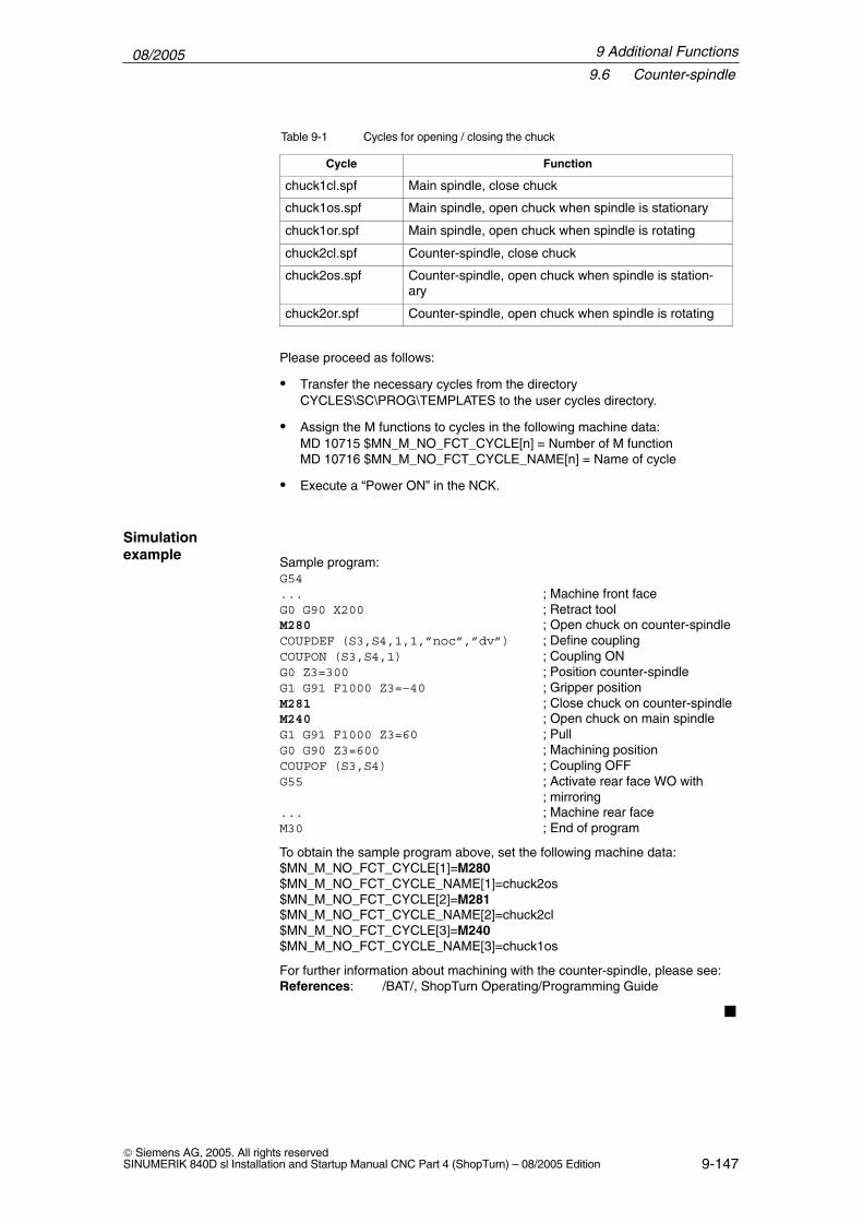
08/20059.6 Counter-spindle
9-147 Siemens AG, 2005. All rights reservedSINUMERIK 840D sl Installation and Startup Manual CNC Part 4 (ShopTurn) – 08/2005 Edition
Table 9-1 Cycles for opening / closing the chuck
Cycle Function
chuck1cl.spf Main spindle, close chuck
chuck1os.spf Main spindle, open chuck when spindle is stationary
chuck1or.spf Main spindle, open chuck when spindle is rotating
chuck2cl.spf Counter-spindle, close chuck
chuck2os.spf Counter-spindle, open chuck when spindle is station-ary
chuck2or.spf Counter-spindle, open chuck when spindle is rotating
Please proceed as follows:
� Transfer the necessary cycles from the directory CYCLES\SC\PROG\TEMPLATES to the user cycles directory.
� Assign the M functions to cycles in the following machine data:MD 10715 $MN_M_NO_FCT_CYCLE[n] = Number of M functionMD 10716 $MN_M_NO_FCT_CYCLE_NAME[n] = Name of cycle
� Execute a “Power ON” in the NCK.
Sample program:G54... ; Machine front faceG0 G90 X200 ; Retract toolM280 ; Open chuck on counter-spindleCOUPDEF (S3,S4,1,1,”noc”,”dv”) ; Define couplingCOUPON (S3,S4,1) ; Coupling ONG0 Z3=300 ; Position counter-spindleG1 G91 F1000 Z3=–40 ; Gripper positionM281 ; Close chuck on counter-spindleM240 ; Open chuck on main spindleG1 G91 F1000 Z3=60 ; PullG0 G90 Z3=600 ; Machining positionCOUPOF (S3,S4) ; Coupling OFFG55 ; Activate rear face WO with
; mirroring... ; Machine rear faceM30 ; End of program
To obtain the sample program above, set the following machine data:$MN_M_NO_FCT_CYCLE[1]=M280$MN_M_NO_FCT_CYCLE_NAME[1]=chuck2os$MN_M_NO_FCT_CYCLE[2]=M281$MN_M_NO_FCT_CYCLE_NAME[2]=chuck2cl$MN_M_NO_FCT_CYCLE[3]=M240$MN_M_NO_FCT_CYCLE_NAME[3]=chuck1os
For further information about machining with the counter-spindle, please see:References: /BAT/, ShopTurn Operating/Programming Guide
�
Simulation example
9 Additional Functions

08/20059.6 Counter-spindle
9-148 Siemens AG, 2005. All rights reserved
SINUMERIK 840D sl Installation and Startup Manual CNC Part 4 (ShopTurn) – 08/2005 Edition
9 Additional Functions
Notes

10-149 Siemens AG, 2005. All rights reservedSINUMERIK 840D sl Installation and Startup Manual CNC Part 4 (ShopTurn) – 08/2005 Edition
Customized User Interface
10.1 Configuring the custom boot screen
With the ShopTurn variant with PCU 50.3 you can create your own customizedimage (e.g. company logo, etc.) which will then appear when the control bootsup.To do so create your own image in 16-color mode. The maximum size of theimage, for the OP010/OP010C/OP010S/OP012, is 224 x 224 pixels and, for theOP015, 352 x 352 pixels.
For the procedure for configuring this and exchanging the boot-up image,please refer to:
References: /IAM/, Commissioning Manual CNC Part 2 (HMI),SINUMERIK 840D sl/840D/840Di/810D,IM4 Commissioning HMI Advanced
10

08/200510.2 Configuring the custom screen
10-150 Siemens AG, 2005. All rights reserved
SINUMERIK 840D sl Installation and Startup Manual CNC Part 4 (ShopTurn) – 08/2005 Edition
10.2 Configuring the custom screen
You can use the “operator interface extension” software to build your own cus-tom screens with specific functional expansions (e.g. custom cycles and mea-suring cycles) or just create your own screen layout (static screens).
References: /IAM/, Commissioning Manual CNC Part 2 (HMI),SINUMERIK 840D sl,840D,840Di,810D,BE1 operator interface extension
In ShopTurn you cannot specify any dimensions for configuring the main part ofthe screen. The position and size of the various main parts of the screen arefixed according to the operating area and mode. This only applies for screensthat can be accessed via entry softkeys.
Table 10-1 Fixed dimensions of ShopTurn screens
Exit screen Softkey Size Dimensions
Manual operatingmode – Zero pointworkpiece / Measureworkpiece
Vertical softkey 1...Vertical softkey 7
X-pos. = 0Y-pos. = 272height = 158 pixelswidth = 556 pixels
Manual operatingmode
Horizontal softkey 8 Large X-pos. = 0Y-pos. = 34height = 396 pixelswidth = 556 pixels
Manual operatingmode
Horizontal softkey 8 Medium X-pos. = 0Y-pos. = 78height = 352 pixelswidth = 556 pixels
Manual operatingmode
Horizontal softkey 8 Small X-pos. = 0Y-pos. = 254height = 176 pixelswidth = 556 pixels
Automatic mode Horizontal softkey 6 Large X-pos. = 0Y-pos. = 34height = 396 pixelswidth = 556 pixels
Automatic mode Horizontal softkey 6 Medium X-pos. = 0Y-pos. = 78height = 352 pixelswidth = 556 pixels
Automatic mode Horizontal softkey 6 Small X-pos. = 0Y-pos. = 254height = 176 pixelswidth = 556 pixels
Program operatingarea –Drilling / milling
Vertical softkey 6 X-pos. = 33Y-pos. = 52height = 378 pixelswidth = 523 pixels
Program operatingarea – Miscellaneous
Vertical softkey 4 X-pos. = 33Y-pos. = 52height = 378 pixelswidth = 523 pixels
Screen properties
10 Customized User Interface

08/200510.2 Configuring the custom screen
10-151 Siemens AG, 2005. All rights reservedSINUMERIK 840D sl Installation and Startup Manual CNC Part 4 (ShopTurn) – 08/2005 Edition
Table 10-1 Fixed dimensions of ShopTurn screens
Exit screen DimensionsSizeSoftkey
Program operatingarea -G code editor
Horizontal softkey 2...Horizontal softkey 6
X-pos. = 0Y-pos. = 34height = 396 pixelswidth = 556 pixels
Alarms operating area Horizontal softkey 7Horizontal softkey 6
X-pos. = 0Y-pos. = 34height = 396 pixelswidth = 556 pixels
Tools / Zero offsets op-erating area
Horizontal softkey 7 X-pos. = 0Y-pos. = 34height = 396 pixelswidth = 556 pixels
Generate code Do not enter a target directory for the program operating area and the manualmode. ShopTurn defines the target file.
The customized static screens can be displayed with the following entry soft-keys, the SC number being the link between the entry softkey and the configu-ration file of the screen. In manual and automatic modes you have the choice between different sizedscreens that fill the following window areas:
� Large: Status area, position display, or program display and input window
� Medium: Position display or program display and input window
� Small: Input window
Table 10-2 Entry softkeys for screens
Exit screen Softkey Size SCxxxx
Manual operating mode Horizontal softkey 8 Large SC818
Horizontal softkey 8 Medium SC8181
Horizontal softkey 8 Small SC8182
Automatic mode Horizontal softkey 6 Small SC826
Horizontal softkey 6 Medium SC8261
Horizontal softkey 6 Large SC8262
Messages / Alarms op-erating area
Horizontal softkey 7 SC857
Messages / Alarms op-erating area
Horizontal softkey 8 SC858
Tools / Zero offsets op-erating area
Horizontal softkey 7 SC867
Entry softkeys
10 Customized User Interface

08/200510.2 Configuring the custom screen
10-152 Siemens AG, 2005. All rights reserved
SINUMERIK 840D sl Installation and Startup Manual CNC Part 4 (ShopTurn) – 08/2005 Edition
Note
The screen size is fixed in ShopTurn (see above “Screen Properties”). Takenote of this in case you would like to program background images, for example,for screens you configured yourself.
Note
Open a user-configured screen before calling a softkey bar.
You can call your own cycles by means of the following access softkeys:
Table 10-3 Entry softkeys for cycles
Exit screen Softkey SCxxxx
Program operating area – Drilling Vertical softkey 6 SC8426
Program operating area – Turning Vertical softkey 6 SC9436
Program operating area – Milling Vertical softkey 6 SC9456
Program operating area – Miscellaneous Vertical softkey 4 SC8454
Note
In manual mode you can also assign your own user cycle to horizontalsoftkey 8. The NC code generated is then collected and you can then start thecycle with “Cycle Start”; (see Subsection 10.2.3. “Integrating measuring cycles).
10 Customized User Interface

08/200510.2 Configuring the custom screen
10-153 Siemens AG, 2005. All rights reservedSINUMERIK 840D sl Installation and Startup Manual CNC Part 4 (ShopTurn) – 08/2005 Edition
You can use the following entry softkeys to display your own measuring cycles,which are to replace the ShopTurn measuring cycles:
Table 10-4 Entry softkeys for measuring cycles
Exit screen Softkey SCxxxx
Manual operating mode – Zero point work-piece
Vertical softkey 1 SC8131
Manual operating mode – Zero point work-piece
Vertical softkey 2 SC8132
Manual operating mode – Zero point work-piece
Vertical softkey 3 SC8133
Manual operating mode – Zero point work-piece
Vertical softkey 4 SC8134
Manual operating mode – Zero point work-piece
Vertical softkey 5 SC8135
Manual operating mode – Zero point work-piece
Vertical softkey 6 SC8136
Manual operating mode – Zero point work-piece
Vertical softkey 7 SC8137
Manual operating mode – Tool measure-ment
Vertical softkey 1 SC8141
Manual operating mode – Tool measure-ment
Vertical softkey 2 SC8142
Manual operating mode – Tool measure-ment
Vertical softkey 3 SC8143
Manual operating mode – Tool measure-ment
Vertical softkey 4 SC8144
Manual operating mode – Tool measure-ment
Vertical softkey 5 SC8145
Manual operating mode – Tool measure-ment
Vertical softkey 6 SC8146
Manual operating mode – Tool measure-ment
Vertical softkey 7 SC8147
10 Customized User Interface

08/200510.2 Configuring the custom screen
10-154 Siemens AG, 2005. All rights reserved
SINUMERIK 840D sl Installation and Startup Manual CNC Part 4 (ShopTurn) – 08/2005 Edition
10.2.1 Transferring cycles to the machining plan
You can transfer all user cycles that you have inserted in the Program operatingarea (including measuring cycles) to the work plan and edit them there. How-ever, the cycles will not be displayed as programming graphics.
Use the “operator interface extension” software to define the cycle. Please notethat the cycle must contain the Generate Code (GC) function and an OUTPUTmethod for NC code to be generated and sent to the NC for execution.
If you call and validate the cycle on the ShopTurn user interface, the cycle willautomatically appear in the work plan. The screen form name of the cycle willappear in the machining plan as plain text.
Sample cycles are available for the following applications:
� Tail stock (TAILSTOK)
� Part gripper (RECEPTAC)
� Bar loader (BARLOAD)
If you want to use these cycles, adapt them to the characteristics of your ma-chine.
Directory CYCLES\SC\PROG\TEMPLATES contains the archive file EQUIP-MENT.ARC which lists the cycles and operator interfaces. The associated textsare imported together with the alarm texts when you install ShopTurn. A readme file with information about how to install is also located in the samedirectory as the archive file.
The cycles for tail stock, part gripper, and bar loader can be seen in the Pro-gram operating area under Miscellaneous ––> Device. You will also find the tailstock cycle in Manual mode (horizontal softkey 8).
The “bar loader” cycle can be linked with a cut-off or stock removal cycle; (seeSample cycle).
Note
If you want to use the sample cycle for bar loader, you must not change itsname (“BARLOAD”).
Sample cycles
Sample cycles –linking “barloader”
10 Customized User Interface

08/200510.2 Configuring the custom screen
10-155 Siemens AG, 2005. All rights reservedSINUMERIK 840D sl Installation and Startup Manual CNC Part 4 (ShopTurn) – 08/2005 Edition
10.2.2 Linking cycles into the machining plan
You can link user cycles into the work plan with the ShopTurn cycles “Posi-tions”.
The name of the cycles to be linked in the work plan is mandatory and must notbe changed:F_DR_Ox with x = 1 to 8
The following variables must be configured within the cycles:
First you must define three variables that are not used until the program step isinserted in the ShopTurn work plan; i.e. you must assign the attribute invisible(wr0) to the variable input field. The variable sequence is as follows:
1. Variable for the next tool, data type String (S)
2. Variable for the position identifier in objects, data type Integer
3. Variable for the sequencer text that is to be displayed in the ShopTurn workschedule, data type character string (S)The easiest way to assign a value to this variable is in a LOAD method.
Two variables for cycles processing must also be defined as well as one vari-able for each toggle field which has a different display content on the interface(e.g. mm/rev) than the internally transferred quantity (e.g. 1). You need to assign the attribute invisible (wr0) to these variables too as they donot have their own input field. You can place the variables in any order.
Note
When an OUTPUT method is used, all variables described above must beconfigured within this method so that they can all be interpreted onrecompilation.
If a particular work step is to be performed not in all positions but only once, the following user variable must be set in the associated cycle F_ONETIME = 1. This also provides the possibility of implementing modal chan-ges for subsequent technologies.
Directory CYCLES\SC\PROG\TEMPLATES contains a sample cycle F_DR_O1.SPF. The associated user interface is configured in fileF_DR_O1.COM. The German and English texts are stored in filesF_DR_TXD.COM and F_DR_TXE.COM. A number of help displays are alsoincluded with the sample cycle.Please see the README.TXT file for information on how to install the cycle.
Name
Variables
Once-onlymachining
Example
10 Customized User Interface

08/200510.2 Configuring the custom screen
10-156 Siemens AG, 2005. All rights reserved
SINUMERIK 840D sl Installation and Startup Manual CNC Part 4 (ShopTurn) – 08/2005 Edition
10.2.3 Integrating measuring cycles
If you wish to integrate your own measuring cycles in Manual mode, verticalsoftkey 8 (VS8) in the new cycles screen acquires a special meaning. All ac-tions that the new measuring cycle is supposed to perform after the “cycle start”key has been pressed must be defined in a PRESS method for VS8. If youpress the “cycle start” button, NC code is generated that is written and executedin a program, i.e. the function Generate Code (GC) must be programmed in thePRESS method for VS8. This in turn means that an OUTPUT method must bedefined.
Note
The user does not have to press VS8; it is triggered internally when the “cyclestart” key is pressed. The VS8 must therefore not be labeled.
Directory CYCLES\SC\PROG\TEMPLATES contains the archive fileF_MS_O1.ARC containing sample cycle F_MS_O1.SPF. The associated userinterface is configured in file F_MS_O1.COM. In Files F_MS_TXD.COM andF_MS_TXE.COM contain the German and English texts, and file EDGE_Z.BMPcontains a help display.Please see the README.TXT file for information on how to install the cycle.
If you want to link user measuring cycles into the operating area program, pro-ceed as described in Subsection 10.2.1 “Transferring Cycles to the MachiningPlan”. A vertical softkey menu will then be created behind the entry softkey “Miscella-neous” → “Zero point workpiece”, via which you can call up your measuringcycles. Such a vertical softkey menu already exists behind the “Miscellaneous”→ “Measure tool” entry softkey.
Manual operatingmode
Example
Program operatingarea
10 Customized User Interface

08/200510.3 ShopTurn Open (PCU 50.3)
10-157 Siemens AG, 2005. All rights reservedSINUMERIK 840D sl Installation and Startup Manual CNC Part 4 (ShopTurn) – 08/2005 Edition
10.3 ShopTurn Open (PCU 50.3)
In ShopTurn Open, the HMI Advanced operating areas “Parameter” (withouttool management and zero offsets), “Services”, “Diagnosis”, and “Start-up” arelocated on the extended horizontal softkey bar.
References: User’s Guide HMI Programming Package Part 1 (BN)
10.3.1 Basic menu bar
There are various methods by which you can integrate Windows applicationsinto the basic menu bar:
� Horizontal softkey 4, i.e. the Messages / Alarms operating area is replaced
� User-assignable softkeys 7 and 8
� User-assignable softkeys 1 to 8 in the extended horizontal softkey menu
There are 3 methods by which you can jump from the Windows application toanother operating area:
� Using the “Menu Select” key on the operator panel, you can return to thebasic menu bar and then select another operating area via a softkey.
� You can configure the keys “Position”, “Program”, “Offset”, “Program Man-ager”, “Alarm” and “Custom” on the operator panel to branch directly intoanother operating area or sub-menu.
� You can configure so-called “PLC keys” to branch into another operatingarea or sub-menu.
References: IAM/, Commissioning Manual CNC Part 2 (HMI), SINUMERIK 840D sl, 840D/840Di/810DBE1 operator interface extensionkeyword “OP hotkeys” and “PLC keys”
Jump intoapplication
Return
10 Customized User Interface

08/200510.4 Operator interface for ShopTurn on the NCU (HMI Embedded)
10-158 Siemens AG, 2005. All rights reserved
SINUMERIK 840D sl Installation and Startup Manual CNC Part 4 (ShopTurn) – 08/2005 Edition
10.4 Operator interface for ShopTurn on the NCU (HMI Em-bedded)
The operating areas “Machine” and “Program” are by default hidden withoutmanufacturer password. In the operating area “Parameter” only the setting dataand the zero offsets can be seen without manufacture password.
You can change the display by means of the following machine data
9272 MM_USER_CLASS_APPLICATION [1] = 1
9272 MM_USER_CLASS_APPLICATION [3] = 1
9273 MM_USER_CLASS_APPLICATION [1] = 1
9273 MM_USER_CLASS_APPLICATION [2] = 1
9273 MM_USER_CLASS_APPLICATION [3] = 1
9273 MM_USER_CLASS_APPLICATION [4] = 1
9273 MM_USER_CLASS_APPLICATION [6] = 1
9273 MM_USER_CLASS_APPLICATION [10] = 1
9414 MM_TM_KIND_TOOLMANAGEMENT = 1
Default setting
10 Customized User Interface
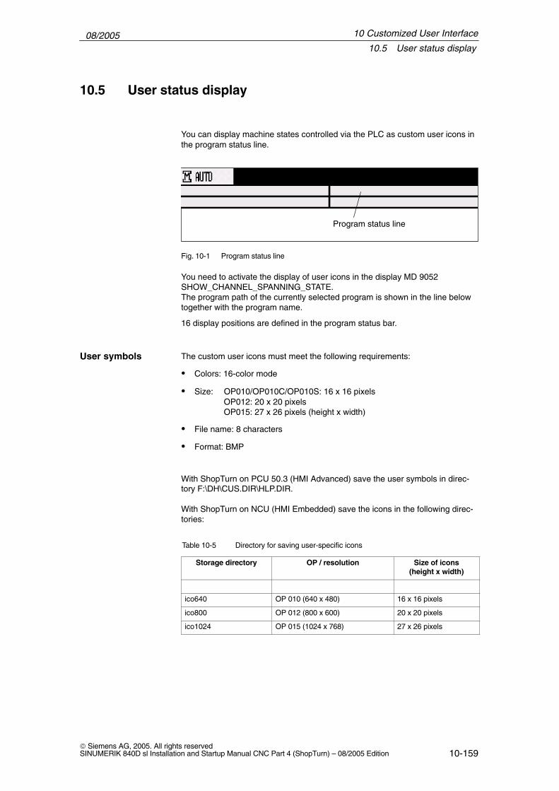
08/200510.5 User status display
10-159 Siemens AG, 2005. All rights reservedSINUMERIK 840D sl Installation and Startup Manual CNC Part 4 (ShopTurn) – 08/2005 Edition
10.5 User status display
You can display machine states controlled via the PLC as custom user icons inthe program status line.
Program status line
Fig. 10-1 Program status line
You need to activate the display of user icons in the display MD 9052SHOW_CHANNEL_SPANNING_STATE.The program path of the currently selected program is shown in the line belowtogether with the program name.
16 display positions are defined in the program status bar.
The custom user icons must meet the following requirements:
� Colors: 16-color mode
� Size: OP010/OP010C/OP010S: 16 x 16 pixelsOP012: 20 x 20 pixelsOP015: 27 x 26 pixels (height x width)
� File name: 8 characters
� Format: BMP
With ShopTurn on PCU 50.3 (HMI Advanced) save the user symbols in direc-tory F:\DH\CUS.DIR\HLP.DIR.
With ShopTurn on NCU (HMI Embedded) save the icons in the following direc-tories:
Table 10-5 Directory for saving user-specific icons
Storage directory OP / resolution Size of icons(height x width)
ico640 OP 010 (640 x 480) 16 x 16 pixels
ico800 OP 012 (800 x 600) 20 x 20 pixels
ico1024 OP 015 (1024 x 768) 27 x 26 pixels
User symbols
10 Customized User Interface

08/200510.5 User status display
10-160 Siemens AG, 2005. All rights reserved
SINUMERIK 840D sl Installation and Startup Manual CNC Part 4 (ShopTurn) – 08/2005 Edition
The user-specific images are stored in directories (icoxxx) in the following sub-directories:
� Manufacturer: \oem\sinumerik\hmi\ico\icoxxx
� User: \oem\sinumerik\hmi\ico\icoxxx
10.5.1 Configuring the user status display
The cross-channel status display is allocated and configured with user symbolsin the HEADER.INI file.
ShopTurn on PCU 50.3 The file HEADER.INI is located in directory F:\HMI_ADV; you must copy it eitherto directory F:\OEM or to directory F:\USER.
In file HEADER.INI in the section User Icons enter the names of the usersymbols and the signal for controlling symbol selection.
Note
If you have already made these entries for HMI Advanced, you do not need tomake them again for ShopTurn.
[User icons]UI_0= <Icons_00.bmp>, <Position>
UI_0: IdentifierIcons_00.bmp: Name of the user iconPosition: Position for display (1 to 16)
...UI_31= <Icons_31.bmp>, <Position>
USER_ICON_BASE = DBx.DBByDBx.DBBy: Signal defined by user for controlling icon
selection
The user icons are addressed bit by bit, i.e. if bit n is set in signal DBx.DBBy,then the user icon with identifier UI_n is displayed.If the bit is reset by the PLC, the associated user icon is deleted in the programstatus display.
If several user symbols are assigned to the same position, the user symbol withthe highest identifier number is displayed.You do not need to specify blank positions.
Additional information can be found in
References: /IAM/, Commissioning Manual CNC Part 2 (HMI),SINUMERIK 840D sl/840D/840Di/810D,IM4 Commissioning HMI Advanced
10 Customized User Interface
08/200510.5 User status display
10-161 Siemens AG, 2005. All rights reservedSINUMERIK 840D sl Installation and Startup Manual CNC Part 4 (ShopTurn) – 08/2005 Edition
On the CompactFlash Card the HEADER.INI file is located in directory siemens\sinumerik\hmi\cfg\
Copy the file HEADER.INI to directory oem\sinumerik\hmi\cfg.Open the file using the editor and assign the user symbols to their desired posi-tions.
Additional information can be found in
References: /IAM/, Commissioning Manual CNC Part 2 (HMI),SINUMERIK 840D sl/840D/840Di/810D,IM4 Commissioning HMI Advanced
ShopTurn on NCU(HMI embedded)
10 Customized User Interface
08/200510.6 OP hotkeys, PLC keys
10-162 Siemens AG, 2005. All rights reserved
SINUMERIK 840D sl Installation and Startup Manual CNC Part 4 (ShopTurn) – 08/2005 Edition
10.6 OP hotkeys, PLC keys
You can configure the keys “Position”, “Program”, “Offset”, “Program Manager”,“Alarm”, and “Custom” on the operator panel to branch to an operating area ofyour choice.
You can configure so-called “PLC keys” to branch to particular operating areas.
You can switch to the following operating areas with the OP hotkeys or PLCkeys:
� ShopTurn on NCU (HMI embedded)From ShopTurn to any ShopTurn operating area.
� PCU 50.3From ShopTurn to any other operating area in ShopTurn.From ShopTurn to any other operating area in HMI Advanced and viceversa.
For information on configuring please refer to:References: IAM/, Commissioning Manual CNC Part 2 (HMI),
SINUMERIK 840D sl, 840D/840Di/810DBE1 operator interface extensionkeyword “OP hotkeys” and “PLC keys”
Note
“PLC keys” in ShopTurn are configured in the file KEYS.INI not via interfaceDB 19.In the file KEYS.INI in section [HMI_INI_FILES] the following entry must bemade:Task6 = shopturn.ini
�
OP hotkeys
PLC keys
Configuring
10 Customized User Interface

11-163 Siemens AG, 2005. All rights reservedSINUMERIK 840D sl Installation and Startup Manual CNC Part 4 (ShopTurn) – 08/2005 Edition
Miscellaneous
11.1 Machine data for protection levels
The machine manufacturer or end user can set operator panel machine data toassign the appropriate protection levels for individual functions and data areasFor a number of data types, it is possible to input different protection levels forread and write access authority.The machine data which can be locked by means of protection levels inShopTurn are listed below:
Operator panel machine data Access to
9182 USER_CLASS_INCH_METRIC Switch over between Inch/metric
9200 USER_CLASS_READ_TOA Read tool offsets
9201 USER_CLASS_WRITE_TOA_GEO Write tool geometry (including type andcutting edge)
9202 USER_CLASS_WRITE_TOA_WEAR Write tool wear (withoutlimit value)
9203 USER_CLASS_WRITE_FINE Write fine tool wear andfine offsets
9206 USER_CLASS_WRITE_TOA_SUPVIS Change limit values for tool monitoring
9210 USER_CLASS_WRITE_ZOA Write rough offsets
9215 USER_CLASS_WRITE_SEA Write setting data
9216 USER_CLASS_READ_PROGRAM Read program (protection level must be ≤ 6)
9217 USER_CLASS_WRITE_PROGRAM Write / edit program(protection level must be ≤ 5)
9218 USER_CLASS_SELECT_PROGRAM Enable program selection(protection level must be ≤ 7)
9222 USER_CLASS_WRITE_RPA Write R parameters
9252 USER_CLASS_TM_SKTOOLLOAD Enable loading of a tool
9253 USER_CLASS_TM_SKTOOLUNLOAD Enable unloading of a tool
9254 USER_CLASS_TM_SKTOOLMOVE Enable relocation of a tool
9258 USER_CLASS_TM_SKNCNEWTOOLE Enable setting up of new cuttingedges
Lockable dataareas
11

08/200511.1 Machine data for protection levels
11-164 Siemens AG, 2005. All rights reserved
SINUMERIK 840D sl Installation and Startup Manual CNC Part 4 (ShopTurn) – 08/2005 Edition
9259 USER_CLASS_TM_SKNCDELTOOL Enable deleting of a tool
9264 USER_CLASS_TM_SKTLNEWTOOL Enable setting up of a new tool
9510 USER_CLASS_DIRECTORY1_P Enable network drive 1
9511 USER_CLASS_DIRECTORY2_P Enable network drive 2
9512 USER_CLASS_DIRECTORY3_P Enable network drive 3
9513 USER_CLASS_DIRECTORY4_P Enable network drive 43
9890 ST_USER_CLASS_MEAS_T_CAL Calibrate tool probe
11 Miscellaneous

08/200511.2 Machine manufacturer cycle
11-165 Siemens AG, 2005. All rights reservedSINUMERIK 840D sl Installation and Startup Manual CNC Part 4 (ShopTurn) – 08/2005 Edition
11.2 Machine manufacturer cycle
The machine manufacturer cycle ST_CUST.SPF is called by the ShopTurn cy-cles. Adapt the cycle if you want to perform one of the following actions:
� Switch between spindle and C axis mode of the main spindle or counter-spindle.Marks _M1, _M2, _M21, _M22(see also Section 9.6 “Counter-spindle”)
� Clamp or release the rotary axes (main spindle / counter-spindle).Marks _M3, _M4, _M23, _M24(see also MD 9843 $MM_ST_ENABLE_SPINDLE_CLAMPING)
� Open, close, flush chuck (main spindle /counter-spindle).Marks _M5 to _M8, _M25 to _M29(see also Section 9.6 “Counter-spindle”)
� Engage / disengage rotating tool (make / break connection to drive).Marks _M41, _M42
� Configure special functions for switchover between machining planes. (Youdo not have to make any settings for cylinder surface transformation or faceend machining with the C axis.)Marks _M61 to _M68
� Position, extend, or retract receptacle for cutting off.Marks _M100, _M101, _M102(see also MD 9841 $MM_ST_ENABLE_PART_OFF_RECEPT)
� Configure special functions for tool changing. (These special functions arecalled after the T command is output.)Marks _M110, _M111, _M112
� Change default for coupling between main spindle and counter-spindle.Mark _M120(see also Section 9.6 “Counter-spindle”)
� Set special properties for program start or program end.Marks _M131, _M135, _M136
The cycle is located in directory CYCLES\SC\PROG\TEMPLATES.
11 Miscellaneous

08/200511.3 Spindle control
11-166 Siemens AG, 2005. All rights reserved
SINUMERIK 840D sl Installation and Startup Manual CNC Part 4 (ShopTurn) – 08/2005 Edition
11.3 Spindle control
For configuration of the spindle control please refer to:
References: /FB1/, Description of Functions, Basic Machine, Spindles (S1)
ShopTurn distinguishes between M2/M30 (end of a ShopTurn program) and theM function set in MD 10714 $MN_M_NO_FCT_EOP (end of a program createdin “Manual” or “MDI” mode).Setting MD 35040 $MA_SPIND_ACTIVE_AFTER_RESET=2 causes the NCKto switch off the spindle in response to M2/M30 but not in response to the Mfunction programmed in MD 10714 $MN_M_NO_FCT_EOP.One of the purposes of this functionality is to allow continuous starting of thespindle in manual mode (e.g. for scratching).
ShopTurn uses the following M functions for end of program:
� M function from MD 10714 $MN_M_NO_FCT_EOP: End of main program,spindle continues
� M2, M30: End of main program and return jump to beginning of program,spindle stops
� M17: End of subprogram and return jump to main program, spindle contin-ues operating
In order to ensure that the rotational direction of the spindle and C axis is cor-rectly displayed in the ShopTurn interface and executed directly for program-med ShopTurn functions you must enter a number of mutually coordinated set-tings. You must base these settings on the actual direction of rotation of thespindle / C axis on the machine.
If you want to use functions cylinder surface transformation and end face ma-chining, start-up must have been correctly performed for the functions. The fol-lowing machine data in particular must be correctly set:24810 $MC_TRACYL_ROT_SIGN_IS_PLUS_124860 $MC_TRACYL_ROT_SIGN_IS_PLUS_224910 $MC_TRANSMIT_ROT_SIGN_IS_PLUS_124960 $MC_TRANSMIT_ROT_SIGN_IS_PLUS_2
In display machine data you stipulate which direction of rotation of the spindle /C axis is to be displayed for M function M3 in the ShopTurn interface.
MD 9822 $MM_ST_DISPL_DIR_MAIN_SPIND_M3MD 9823 $MM_ST_DISPL_DIR_SUB_SPIND_M3MD 9824 $MM_ST_DISPL_DIR_MAIN_C_AX_INVMD 9825 $MM_ST_DISPL_DIR_SUB_C_AX_INV
The direction of spindle rotation (M3/M4) is assigned to the positive rotationaldirection of the C axis via interface signal DB3n.DBX17.6 (where n = index ofthe relevant C axis). The bit defines whether M3 and C+ rotate in the same di-rection (=0) or in opposite directions (=1).
End of program
Direction ofrotation
11 Miscellaneous

08/200511.3 Spindle control
11-167 Siemens AG, 2005. All rights reservedSINUMERIK 840D sl Installation and Startup Manual CNC Part 4 (ShopTurn) – 08/2005 Edition
The following settings are possible for the main spindle and the counter-spindle;the settings for machine data 9822 and 9823 depend on the direction in whichthe user views the coordinate axis. The settings for machine data 9824 and9825 and the interface signal DB3n.DBX17.6 must be observed.
Table 11-1 Direction of rotation of main spindle
Main spindle direction of rotation MD 9822* MD 9824 DB3n.DBX17.6
M3C+
0 0 0
M4C+
1 0 1
C+ M3
1 1 0
C+ M4
0 1 1
The setting of machine data marked with “*” assumes that the viewing directionwas towards the negative coordinate axis. If on the other hand you are lookingtowards the positive coordinate axis, you need to reverse the values, i.e. swap“0” and “1”. Machine data 9822 is only relevant for display in the ShopTurn interface, not forcorrect operation on the machine.
11 Miscellaneous

08/200511.3 Spindle control
11-168 Siemens AG, 2005. All rights reserved
SINUMERIK 840D sl Installation and Startup Manual CNC Part 4 (ShopTurn) – 08/2005 Edition
Table 11-2 Direction of rotation of counter-spindle
Counter-spindle direction of rotation MD 9823* MD 9825 DB3n.DBX17.6
M3 C+
1 0 0
M4C+
0 0 1
C+M3
0 1 0
C+M4
1 1 1
The setting of machine data marked with “*” assumes that the viewing directionwas towards the negative coordinate axis. If on the other hand you are lookingtowards the positive coordinate axis, you need to reverse the values, i.e. swap“0” and “1”. Machine data 9823 is only relevant for display in the ShopTurn interface, not forcorrect operation on the machine.
11 Miscellaneous

08/200511.4 ISO dialects
11-169 Siemens AG, 2005. All rights reservedSINUMERIK 840D sl Installation and Startup Manual CNC Part 4 (ShopTurn) – 08/2005 Edition
11.4 ISO dialects
You can also create and run ISO dialect programs under ShopTurn. For moreinformation on how to set up ISO dialects please refer to the following documen-tation:References: /FBFA/, Description of Functions ISO Dialects
11 Miscellaneous
08/200511.5 Automatically generated programs
11-170 Siemens AG, 2005. All rights reserved
SINUMERIK 840D sl Installation and Startup Manual CNC Part 4 (ShopTurn) – 08/2005 Edition
11.5 Automatically generated programs
ShopTurn creates certain programs automatically during operation.
Directory of part programs:
The program is created when a function is executed in “Manual” mode. Theprogram is started via an asynchronous subprogram.
The last parameter values entered in a screen are saved in these programs,depending on the unit of measurement. (INPUT_DATA_MM = values with theunit “mm”; INPUT_DATA_IN = values with the unit “Inch”)
Directory start-up:
Data which needs to remain stored when the machine is next switched off (e.g.the last selected program) is saved in this program.
CMM_SINGLE
INPUT_DATA_MMINPUT_DATA_IN
REM_DATA.TRC
11 Miscellaneous

08/200511.6 Manual machine
11-171 Siemens AG, 2005. All rights reservedSINUMERIK 840D sl Installation and Startup Manual CNC Part 4 (ShopTurn) – 08/2005 Edition
11.6 Manual machine
“Manual machine” is an option (order number 6FC5 800-0AP11-0YB0).
The option “Manual machine” allows you to work with large cycles in manualmode without having to write programs especially for this purpose.
For an exact description of the cycles available in “Manual” mode and how touse the option “Manual machine”, please refer to:
References: /BAT/, ShopTurn Operating/Programming Guide
Manual operation in the “Manual” mode is based on the jogging functions in theNCK.
For tool selection enter the name of the tool and start by means of “Cycle start”.
� Turret revolverWith “Cycle start” the turret revolver starts to rotate.
� MultifixWith “Cycle start” tool correction is activated.
SD 42600 JOG_FEED_PER_REV_SOURCE is used to stipulate whether oneor two feed fields should be available in the basic screen “Manual”.
� 42600 JOG_FEED_PER_REV_SOURCE = 0One feed field is provided.The input field can be switched from mm/min to mm/rev. SD 41100JOG_REV_IS_ACTIVE is then altered from 0 (mm/min) to 1 (mm/rev).
� 42600 JOG_FEED_PER_REV_SOURCE = –3Feed fields for mm/min and mm/rev are provided.The jogging function only uses the mm/rev feed if the main spindle is run-ning. Otherwise it uses the mm/min value.
The input field for the rotational speed can be switched over between rpm andm/min.SD 43206 SA_SPIND_SPEED_TYPE is set accordingly to the appropriateG code (G94, G95, G96).
� rpmSD 43200 SPIND_S is written.
� m/minSD 43202 SPIND_CONSTCUT_S is written.
Option
Tool selection
Feed rate
Rotational speed(main spindle)
11 Miscellaneous

08/200511.6 Manual machine
11-172 Siemens AG, 2005. All rights reserved
SINUMERIK 840D sl Installation and Startup Manual CNC Part 4 (ShopTurn) – 08/2005 Edition
You have the following possibilities for starting the spindle:
� MD 9897 MM_ST_OPTION_MASK_MAN_FUNC Bit 0 = 1Spindle start by means of “Cycle start”.Select rpm or m/min and enter the desired value.Select the direction of rotation and start the spindle by means of “Cyclestart”.
� MD 9897 MM_ST_OPTION_MASK_MAN_FUNC Bit0 = 0Spindle start by means of external switch.Select rpm or m/min and enter the desired value.DB3x.DBB30.1 starts the spindle rotating clockwise.DB3x.DBB30.2 starts the spindle rotating counter-clockwise.DB3x.DBB30.0 stops the spindle.
The rotational speed is displayed in rpm.SD 43206 SA_SPIND_SPEED_TYPE is set.SD 43200 SPIND_S is written.
You have the following possibilities for starting the spindle:
� MD 9897 MM_ST_OPTION_MASK_MAN_FUNC Bit 0 = 1Spindle start by means of “Cycle start”.In the input field enter the desired value for the rotational speed.Select the direction of rotation and start the spindle by means of “Cyclestart”.
� MD 9897 MM_ST_OPTION_MASK_MAN_FUNC Bit0 = 0Spindle start by means of external switch.In the input field enter the desired value for the rotational speed.DB3x.DBB30.1 starts the spindle rotating clockwise.DB3x.DBB30.2 starts the spindle rotating counter-clockwise.DB3x.DBB30.0 stops the spindle.
Rotational speed(driven tool)
11 Miscellaneous

08/200511.7 Action log
11-173 Siemens AG, 2005. All rights reservedSINUMERIK 840D sl Installation and Startup Manual CNC Part 4 (ShopTurn) – 08/2005 Edition
11.7 Action log
You can log sequences of operations in ShopTurn in the action log to obtain ahistory of events for later examination.
For detailed information regarding the action log please refer to:References: /IAM/, Commissioning Manual CNC Part 2 (HMI),
SINUMERIK 840D sl/840D/840Di/810D,IM2 Commissioning HMI Embedded (sl)
Please refer to directory DOCUMENTATION\WINDOWLISTS on the ShopTurnCD ROM for the assignment between ID numbers listed in the log and the cor-responding ShopTurn windows.
Note
If you are using a PCU 50.3 with HMI Advanced and wish to log ShopTurnoperating sequences, you must enter the settings for the action log directly inMD 9012 $MM_ACTION_LOG_MODE. The log is stored in theF:\MMCOW32\TMP\_AC_LOG.BIN file. No support for display or readout of thisfile is provided.
11 Miscellaneous

08/200511.8 Version display
11-174 Siemens AG, 2005. All rights reserved
SINUMERIK 840D sl Installation and Startup Manual CNC Part 4 (ShopTurn) – 08/2005 Edition
11.8 Version display
You can see the ShopTurn version in the boot screen.
The version data of the installed system software are output in a version display.
� For this purpose switch to the CNC ISO operator interface.
� Select the menu “Diagnostics” ––> “Service displays” ––> “Version”.
For detailed information regarding the version display please refer to:References: /IAM/, Commissioning Manual CNC Part 2 (HMI),
SINUMERIK 840D sl/840D/840Di/810D,IM2 Commissioning HMI Embedded (sl)
/BAD/ Operating instructions HMI Advanced,SINUMERIK 840D sl/840D/840Di/810DBEM/ Operating instructions HMI Embedded (sl),SINUMERIK 840D sl/840D/840Di/810D
�
11 Miscellaneous
A-175 Siemens AG, 2005. All rights reservedSINUMERIK 840D sl Installation and Startup Manual CNC Part 4 (ShopTurn) – 08/2005 Edition
Abbreviations
Asynchronous Subroutine
Mode group
Buffer
Computerized Numerical Control
Communication: Component of NC control that performs and coordinates com-munication.
Data Block
Data Block Byte
Data Block Double Word
Data Block Word
Data Block Bit
Function Call, Function block in the PLC
Global User Data
Handheld Programming Unit
Start-up
Machine control panel
Machine Data
Manual Data Automatic
Main Program File: Part program (main program)
Multi-Port Interface
Numerical controlThe NC control comprises the components NCK, PLC, PCU and COM.
ASUB
BAG
BUFF
CNC
COM
DB
DBB
DBD
DBW
DBX
FC
GUD
HPU
IBN
MCP
MD
MDA
MPF
MPI
NC
A

08/2005
A-176 Siemens AG, 2005. All rights reserved
SINUMERIK 840D sl Installation and Startup Manual CNC Part 4 (ShopTurn) – 08/2005 Edition
Numerical Control Kernel:Component of NC control that executes programs and basically coordinatesmovements for the machine tool.
Numerical Control Unit: NC module
Organization block in the PLC
Operator Panel
Personal Computer
Personal Computer UnitComponent of NC control allowing communication between operator and ma-chine.
Programming device
Programmable Logic ControlComponent of NC control for processing machine tool control logic
Random Access Memory, i.e. program memory that can be read and written to
Setting Data
SoftKey
Sub Program File: Subprogram
Statement List
Software
Tool number
Tool management
Tool Offset Active Identifier for tool offsets
Tool
�
NCK
NCU
OB
OP
PC
PCU
PG
PLC
RAM
SD
SK
SPF
STL
SW
T No.
TM
TOA
WZ
A Abbreviations

B-177 Siemens AG, 2005. All rights reservedSINUMERIK 840D sl Installation and Startup Manual CNC Part 4 (ShopTurn) – 08/2005 Edition
References
Documentation
A list of documents, updated on a monthly basis, is available on the Internet forthe available languages at:
http://www.siemens.com/motioncontrol
Select the menu items ––> “Support” ––> “Technical documentation” ––>“Overview of documents”, or “DOConWEB”.
B

08/2005
B-178 Siemens AG, 2005. All rights reserved
SINUMERIK 840D sl Installation and Startup Manual CNC Part 4 (ShopTurn) – 08/2005 Edition
B References
Notes

Index-179 Siemens AG, 2005. All rights reservedSINUMERIK 840D sl Installation and Startup Manual CNC Part 4 (ShopTurn) – 08/2005 Edition
Index
AAbbreviations, A-175Action log, 11-173
BBar loader, 10-154Basic components, 1-13
CConfiguration file, 8-89
Variables, 8-91Coolant, 8-108Custom screen, 10-150Cycles, user-configured, 10-150Cylinder surface transformation, 9-131
DData transfer, 4-19DB 71, 8-99DB 72, 8-100DB 73, 8-101Direction of rotation, 11-166Display machine data, 7-45
Tool management, 8-107
EEnd face machining, 9-131End of program, 11-166Example source files, 5-29
FFB110, 8-97FC 100, 8-97
GGeneral conditions, 2-15
HHardware, 1-13
Basic components, 1-13Operator control components, 1-13
IInclined axis, 9-140Initial start-up, 4-21Input signals, 6-38Interface DB 19, 6-33Interface signals, 6-33Interface signals for ShopTurn, 5-31ISO dialects, 11-169
MMachine data, 7-43
Display, 7-45NCK, 7-43ShopTurn, 7-45
Machine manufacturer cycle, 11-165Manual machine, 11-171Measuring cycle, display machine data, 9-128Measuring cycles, 9-127
Support, 9-143
NNC machine data, tool management, 8-81NCK startup, 4-25Network, 9-130
OOP hotkeys, 10-162Operator control components, 1-13Output signals, 6-40
PPart gripper, 10-154PCU 50.3, start-up, 4-23
C

08/2005
Index-180 Siemens AG, 2005. All rights reserved
SINUMERIK 840D sl Installation and Startup Manual CNC Part 4 (ShopTurn) – 08/2005 Edition
PLCInterface signals, 6-33Program, 5-29Program structure, 5-29
PLC keys, 10-162PLC start-up, 4-24Programs, generated automatically, 11-170
RReferences, B-177Reserved Functions, 3-17
SScreen, user-configured, 10-150Setup feed rate, 7-44ShopTurn interface DB 82, earlier, 6-38ShopTurn on NCU (HMI embedded)
Settings for operator interface, 10-158Start-up, 4-23
ShopTurn Open, 10-157ShopTurn-Software, 4-19Software start-up, 4-19Special axis, 7-66Spindle, 8-108Spindle control, 11-166ST_CUST, 11-165Start softkey, 10-150, 10-151Start-up
Initial, 4-21NCK, 4-25PCU 50.3, 4-23PLC, 4-24PLC tool management, 8-95Sequence, 4-21ShopTurn on NCU (HMI embedded), 4-23Software, 4-19Tool management NCK, 8-80
Status display, 10-159Support, measuring cycles, 9-143
TTail stock, 10-154to_turn.ini, 8-114Tool list, coolant and direction of rotation, 8-108Tool management, 8-77
Blocks, 8-97Configuration file, 8-89Configuring the operator interface, 8-112Coolant, 8-108Display machine data, 8-107NCK machine data, 8-81NCK start-up, 8-80Overview of functions, 8-77PLC installation and start-up, 8-95Spindle, 8-108
TRAANG, 9-140TRACYL, 9-131TRANSMIT, 9-131Turret revolver, manual movement, 8-109
UUser status display, 10-159
VVersion display, 11-174
WWindow ID, 11-173
C Index
From
Name
Company/Dept.
Street
Zip code: Town:
Phone: /
Suggestions
Corrections
For Publication/Manual:
SINUMERIK 840D sl
ShopTurn
Manufacturer/ServiceDocumentation
Installation and Startup Manual
Order number: 6FC5397-5AP10-0BA0Edition: 08/2005
If you find any errors when readingthis publication, please use this formto notify us.Suggestions for improvement arealso welcome.
To SIEMENS AGA&D MC BMSPostfach 3180
D-91050 ERLANGEN, GERMANYPhone: +49 (0) 180 5050-222 [Hotline]Fax: +49 (0) 9131 98-63315 [Documentation]E-mail: mailto:[email protected]
Fax: /
Suggestions and/or corrections