Embed Size (px)
Citation preview

P-DUKE Technology Co., Ltd. www.pduke.com 2021.02.25 Page 1
Automation Datacom IPC
Industry Measurement Telecom
Automobile Boat Charger
Medical PV Railway
PART NUMBER STRUCTURE
PSR02 - 12 S 05 - HS Series Name
Input Output Output Heat-sink
Voltage Quantity Voltage Options (VDC) (VDC)
05:3.0~5.5 S:Single 1P2:1.2 : No Heat-sink
12:4.6~36 1P5:1.5 HS: Heat-sink
24:12~36 1P8:1.8 * See table as below 2P5:2.5 3P3:3.3 05:5 6P5:6.5 09:9 12:12 15:15

PSR02 Series
P-DUKE Technology Co., Ltd. www.pduke.com 2021.02.25 Page 2
TECHNICAL SPECIFICATION All specifications are typical at nominal input, full load and 25℃ unless otherwise noted
Model Number
Input Range Output Voltage Output Current
@Full Load Input Current @ No Load
Efficiency Maximum Capacitor Load
Min. Vin Max. Vin VDC VDC A mA % % μF
PSR02-05S1P2 3.0 ~ 5.5 1.2
2 1
90 86 2500
PSR02-05S1P5 3.0 ~ 5.5 1.5 91 88 2000
PSR02-05S1P8 3.0 ~ 5.5 1.8 92 90 1600
PSR02-05S2P5 3.8 ~ 5.5 2.5 95 92 1200
PSR02-12S1P2 4.6 ~ 36 1.2 84 75 2500
PSR02-12S1P5 4.6 ~ 36 1.5 86 77 2000
PSR02-12S1P8 4.6 ~ 36 1.8 87 79 1600
PSR02-12S2P5 4.6 ~ 36 2.5 89 83 1200
PSR02-12S3P3 4.75 ~ 36 3.3 91 86 900
PSR02-12S05 6.5 ~ 36 5.0 94 89 600
PSR02-12S6P5 9.0 ~ 36 6.5 94 91 470
PSR02-24S09 12 ~ 36 9.0 95 92 330
PSR02-24S12 15 ~ 36 12 95 93 270
PSR02-24S15 18 ~ 36 15 96 94 200
INPUT SPECIFICATIONS
Parameter Conditions Min. Typ. Max. Unit Operating input voltage range PSR02-05S1P2
PSR02-05S1P5 PSR02-05S1P8 PSR02-05S2P5 PSR02-12S1P2 PSR02-12S1P5 PSR02-12S1P8 PSR02-12S2P5 PSR02-12S3P3 PSR02-12S05 PSR02-12S6P5 PSR02-24S09 PSR02-24S12 PSR02-24S15
3.0 3.0 3.0 3.8 4.6 4.6 4.6 4.6
4.75 6.5 9.0 12 15 18
5.0 5.0 5.0 5.0 12 12 12 12 12 12 12 24 24 24
5.5 5.5 5.5 5.5 36 36 36 36 36 36 36 36 36 36
VDC
For PSR02-12S□□ and PSR02-24S□□, only if the input will be switched electromechanically, the input should install an external 22μF/50V E/C.
Start up time Constant resistive load Power up 5 ms Input filter Capacitor type

PSR02 Series
P-DUKE Technology Co., Ltd. www.pduke.com 2021.02.25 Page 3
OUTPUT SPECIFICATIONS Parameter Conditions Min. Typ. Max. Unit
Voltage accuracy -2.0 +2.0 % Line regulation Low Line to High Line at Full Load -0.5 +0.5 % Load regulation No Load to Full Load -1.0 +1.0 % Ripple and noise Measured by 20MHz bandwidth
mVp-p Vout≦6.5V Vout≧9.0V
50 75
Temperature coefficient -0.02 +0.02 %/℃ Dynamic load response 50% load step change Peak deviation 24S□□ 300 500 mV
Others 150 250 mV Recovery time All 100 200 μs
Over load protection % of Iout rated; Hiccup mode 05S□□
Others
8 3.6
A
Short circuit protection Continuous, automatics recovery
GENERAL SPECIFICATIONS
Parameter Conditions Min. Typ. Max. Unit Switching frequency 05S□□
Others 1200
410
kHz
Safety meets IEC/ EN/ UL62368-1 Case material Non-conducted black plastic Potting material Silicone (UL94 V-0) Weight 2.6g(0.092oz) MTBF MIL-HDBK-217F, Full load 1.352x10⁷ hrs
ENVIRONMENTAL SPECIFICATIONS
Parameter Conditions Min. Typ. Max. Unit Operating ambient temperature With derating -40 +100 ℃ * For high output power of PSR02-24S□□ has an optional heat-sink with suffix
HS, which is able to be operated at least 50℃ ambient temperature without derating when applied input voltage doesn’t exceed 30V.
Other models can meet this condition without heat-sink, and can install the heat-sink for higher operating ambient temperature as well.
Maximum case temperature 105 ℃ Over temperature protection Internal IC junction 150 ℃ Storage temperature range -55 +125 ℃ Thermal shock MIL-STD-810F Vibration MIL-STD-810F Relative humidity 5% to 95% RH
CAUTION: This power module is not internally fused. An input line fuse must always be used.

PSR02 Series
P-DUKE Technology Co., Ltd. www.pduke.com 2021.02.25 Page 4
CHARACTERISTIC CURVE
PSR02-12S05 Derating Curve PSR02-12S05-HS Derating Curve
PSR02-12S05 Efficiency vs. Output Load PSR02-12S05 Efficiency vs. Input Voltage
PSR02-24S15 Derating Curve PSR02-24S15-HS Derating Curve
PSR02-24S15 Efficiency vs. Output Load PSR02-24S15 Efficiency vs. Input Voltage

PSR02 Series
P-DUKE Technology Co., Ltd. www.pduke.com 2021.02.25 Page 5
FUSE CONSIDERATION This power module is not internally fused. An input line fuse must always be used. This encapsulated power module can be used in a wide variety of applications, ranging from simple stand-alone operation to an integrated part of sophisticated power architecture. To maximum flexibility, internal fusing is not included; however, to achieve maximum safety and system protection, always use an input line fuse. The input line fuse suggest as below:
Model Fuse Rating
Fuse Type (A)
PSR02-05S□□ 2 Slow-Blow
PSR02-12S1P2、12S1P5、12S1P8 1.6 Slow-Blow
PSR02-12S2P5、12S3P3、12S05、12S6P5 2.5 Slow-Blow
PSR02-24S□□ 3.15 Slow-Blow
The table based on the information provided in this data sheet on inrush energy and maximum DC input current at low Vin.
MECHANICAL DRAWING PSR02-□□S□□
PIN CONNECTION PIN DEFINE 1 +Vin 2 GND 3 +Vout
1. All dimensions in inch [mm] 2. Tolerance :x.xx±0.02 [x.x±0.5]
x.xxx±0.01 [x.xx±0.25] 3. Pin dimension tolerance ±0.004[0.10]
PSR02 Series
P-DUKE Technology Co., Ltd. www.pduke.com 2021.02.25 Page 6
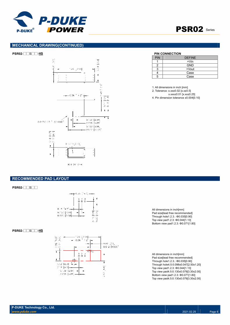
MECHANICAL DRAWING(CONTINUED) PSR02-□□S□□-HS PIN CONNECTION
PIN DEFINE 1 +Vin 2 GND 3 +Vout 4 Case 5 Case
1. All dimensions in inch [mm] 2. Tolerance :x.xx±0.02 [x.x±0.5]
x.xxx±0.01 [x.xx±0.25] 4. Pin dimension tolerance ±0.004[0.10]
RECOMMENDED PAD LAYOUT PSR02-□□S□□
All dimensions in inch[mm] Pad size[lead free recommended] Through hole1.2.3.: Φ0.035[0.90] Top view pad1.2.3: Φ0.044[1.13] Bottom view pad1.2.3: Φ0.071[1.80]
PSR02-□□S□□-HS
All dimensions in inch[mm] Pad size[lead free recommended] Through hole1.2.3.: Φ0.035[0.90] Through hole4.5:0.098x0.047[2.50x1.20] Top view pad1.2.3: Φ0.044[1.13] Top view pad4.5:0.130x0.079[3.30x2.00] Bottom view pad1.2.3: Φ0.071[1.80] Top view pad4.5:0.130x0.079[3.30x2.00]

PSR02 Series
P-DUKE Technology Co., Ltd.
Tel Fax Email Web Add
+886-4-2359-0668 +886-4-2359-1337 [email protected] www.pduke.com No. 36, 22nd Rd., Taichung Industrial Park, Taichung, Taiwan, R.O.C.
2021.02.25 Page 7
THERMAL CONSIDERATIONS The power module operates in a variety of thermal environments. However, sufficient cooling should be provided to help ensure reliable operation of the unit. Heat is removed by conduction, convection, and radiation to the surrounding Environment. Proper cooling can be verified by measuring the point as the figure below. The temperature at this location should not exceed 100℃. When Operating, adequate cooling must be provided to maintain the test point temperature at or below 100℃. Although the maximum point Temperature of the power modules is 100℃, you can limit this Temperature to a lower value for extremely high reliability. The unit will shutdown if the internal IC junction exceeds 150℃ (typical), but the thermal shutdown is not intended as a guarantee that the unit will survive temperature beyond its rating. The module will automatically restarts after it cools down. Thermal test condition with vertical direction by natural convection (20LFM) and mounted on a 30x30mm PCB with 1oz copper and 0.8mm thickness.
TOP VIEW
30 x 30 mm PCB


![DQG SDLG IRU - HAFEDhafed.gov.in/sites/default/files/2020-08/Tender Doc Silo... · 2020. 8. 17. · m 0hdvxuhphqw 5hlqirufhphqw lqfoxglqj dxwkrul]hg vsdfhu eduv fkdluv dqg ods sdjhv](https://img.pdfslide.us/doc/110x75/60b18e78d83ab375935f008f/dqg-sdlg-iru-doc-silo-2020-8-17-m-0hdvxuhphqw-5hlqirufhphqw-lqfoxglqj.jpg)


![0HDVXUHPHQW RI WKH 3KDVH 'LIIHUHQFH EHWZHHQ … · 2019. 7. 11. · 7kh 6hwxs (= 5rkgh 6fkzdu] 0hdvxuhphqw ri wkh 3kdvh 'liihuhqfh ehwzhhq vhyhudo 6ljqdov 7kh 6hwxs %orfn gldjudp](https://img.pdfslide.us/doc/110x75/60e3e6de07df745ae6427f73/0hdvxuhphqw-ri-wkh-3kdvh-liihuhqfh-ehwzhhq-2019-7-11-7kh-6hwxs-5rkgh-6fkzdu.jpg)