Embed Size (px)
Citation preview
BARTELL MORRISON INC. BARTELL MORRISON (USA) LLC 375 ANNAGEM BLVD, MISSISSAUGA, ONTARIO, CANADA, L5T 3A7, 905-364-4200 FAX 905-364-4201
25 INDUSTRIAL DRIVE, KEYPORT, NEW JERSEY, USA, 07735, 732-566-5400 FAX 732-5444 Doc. # OIPB–B09011
Orig. Rel. – 05/2007 Curr. Rev. – 12
Rev. Date – 07/2015
0B
OWNER’S MANUAL & PARTS BOOK
9BSURFACE PREPARATION SYSTEMS (SPS)
10BPOWERFULL - EFFICIENT - DEPENDABLE
SURFACE PREPARATION SYSTEM OWNER’S MANUAL & PARTS BOOK
BARTELL MORRISON INC. BARTELL MORRISON (USA) LLC 375 ANNAGEM BLVD, MISSISSAUGA, ONTARIO, CANADA, L5T 3A7, 905-364-4200 FAX 905-364-4201
25 INDUSTRIAL DRIVE, KEYPORT, NEW JERSEY, USA, 07735, 732-566-5400 FAX 732-566-5444
- 2 -
U
SAFETY PRECAUTIONS
DANGER
EXPLOSION HAZARD Never operate the machine in an explosive atmosphere, near combustible materials or where ventilation does not clear exhaust fumes.
WARNING
BURN HAZARD Never come into contact with the engine or muffler when engine is operating or shortly after it is turned off. Serious burns may occur.
CAUTION
MOVING PARTS Before starting the machine ensure that all guards and safety devices are in place and functioning properly.
CAUTION
MACHINE DAMAGE Advance cutter depth in small increments to avoid premature blade wear or damage.
ATTENTION
READ OWNERS MANUAL Read and understand operator's manual before using this machine. Failure to follow operating instructions could result in serious injury or death.
!
!
!
!
!
SURFACE PREPARATION SYSTEM OWNER’S MANUAL & PARTS BOOK
BARTELL MORRISON INC. BARTELL MORRISON (USA) LLC 375 ANNAGEM BLVD, MISSISSAUGA, ONTARIO, CANADA, L5T 3A7, 905-364-4200 FAX 905-364-4201
25 INDUSTRIAL DRIVE, KEYPORT, NEW JERSEY, USA, 07735, 732-566-5400 FAX 732-566-5444
- 3 -
TABLE OF CONTENTS
QUALITY ASSURANCE/MACHINE BREAK-IN ..................................................................... 4 SURFACE PREPARATION SYSTEM WARRANTY .............................................................. 5 MAINTENANCE RECORD ...................................................................................................... 6 ROUTINE SERVICE INTERVALS .......................................................................................... 7 FOREWORD ........................................................................................................................... 9 SAFETY PRECAUTIONS ....................................................................................................... 9 OPERATING PRINCIPLE ....................................................................................................... 9 WORKING WITH THE SPS .................................................................................................... 9 CUTTER LIFE ......................................................................................................................... 9 GENERAL APPLICATION ...................................................................................................... 9 TYPICAL APPLICATIONS .................................................................................................... 10 SAFETY PRECAUTIONS ..................................................................................................... 10 ASSEMBLY INSTRUCTIONS ............................................................................................... 10 1. HANDLE INSTALLATION .................................................................................................. 10 2. EDGER INSTALLATION ................................................................................................... 11 3. STOP-SWITCH INSTALLATION ....................................................................................... 11 STARTING AND STOPPING PROCEDURE ........................................................................ 12 MAINTENANCE .................................................................................................................... 12 BEARING REPLACEMENT PROCEDURES ....................................................................... 13 A. SEALED BEARING REPLACEMENT - OUTBOARD SIDE .............................................. 13 B. BEARING REPLACEMENT - DRIVER OR "V" BELT SIDE .............................................. 13 CUTTER CAGE REMOVAL & CUTTER CHANGE .............................................................. 13 EDGER CAGE REMOVAL .................................................................................................... 13 STORAGE ............................................................................................................................. 14 LUBRICATION, ENGINE OIL ............................................................................................... 14 ASSEMBLY DRAWINGS AND PARTS LIST ....................................................................... 15 1. SP8 GAS ASSEMBLY (FIGURE 1) .................................................................................. 16
SP8 GAS PARTS LIST ...................................................................................................... 17 2. SP8 ELECTRIC ASSEMBLY (FIGURE 2) ........................................................................ 18
SP8 ELECTRIC PARTS LIST ........................................................................................... 19 3. SP8 AIR ASSEMBLY (FIGURE 3) .................................................................................... 21
SP8 AIR PARTS LIST ....................................................................................................... 22 4. HANDLE ASSEMBLY (FIGURE 4) ................................................................................... 24
HANDLE ASSEMBLY PARTS LIST ................................................................................. 25 5. REAR WHEEL ASSEMBLY (FIGURE 5) .......................................................................... 26
REAR WHEEL ASSEMBLY PARTS LIST ........................................................................ 27 TROUBLESHOOTING .......................................................................................................... 28 APPLICATIONS. CUTTERS AND CAGES INFORMATION ................................................ 29 SPECIFICATIONS ................................................................................................................. 30 EC DECLARATION ............................................................................................................... 31 NOTES .................................................................................................................................. 33
SURFACE PREPARATION SYSTEM OWNER’S MANUAL & PARTS BOOK
BARTELL MORRISON INC. BARTELL MORRISON (USA) LLC 375 ANNAGEM BLVD, MISSISSAUGA, ONTARIO, CANADA, L5T 3A7, 905-364-4200 FAX 905-364-4201
25 INDUSTRIAL DRIVE, KEYPORT, NEW JERSEY, USA, 07735, 732-566-5400 FAX 732-566-5444
- 4 -
QUALITY ASSURANCE / MACHINE BREAK IN The Bartell Surface Preparation System is the product of extensive engineering development designed to give long life and unmatched performance. The SPS’s are shipped completely assembled with the exception of attaching the handle, and only require filling with fuel and a brief check of lubricant levels in preparation for operation. You can help ensure that your Surface Preparation machine will perform at top levels by observing a simple routing on first use. Consider that your new SPS is like a new car. Just as you would break in a new car to the road or any new machine to the job, you should start gradually and build up to full use. Learn what your machine can do and how it will respond. Refer to the engine manufacturer’s manual for run-in times. Full throttle and control may be used after this time period, as allowed by material. This will serve to further break in the machine on your specific application, as well as provide you with additional practice using the machine. We thank you for the confidence you have placed in us by purchasing a Bartell Surface Preparation System and wish you many years of satisfied use.
SURFACE PREPARATION SYSTEM OWNER’S MANUAL & PARTS BOOK
BARTELL MORRISON INC. BARTELL MORRISON (USA) LLC 375 ANNAGEM BLVD, MISSISSAUGA, ONTARIO, CANADA, L5T 3A7, 905-364-4200 FAX 905-364-4201
25 INDUSTRIAL DRIVE, KEYPORT, NEW JERSEY, USA, 07735, 732-566-5400 FAX 732-566-5444
- 5 -
1BUSURFACE PREPARATION SYSTEM WARRANTY
Bartell agrees to furnish without charge, F.O.B. our plant, a replacement for any part or portion thereof, Bartell SPS Machine, save and except, all cutting tools and holders, drive belts, power units, and/or electrical controls which prove upon our examination, to be defective in either material or workmanship within a period of 90 days from date of purchase, provided that notice of such defective part or portion thereof is given to Bartell Ltd. within the said period of 90 days. No further or other guarantee or warranty expressed or implied in connection with the sale of the SPS Machine is given and our sole liability consists in replacing defective parts or portions aforesaid. We shall not be responsible for any special, indirect or consequential damages arising in any manner whatsoever. This guarantee is for the sole benefit of the original purchaser. Our responsibility under this guarantee ends in the case the original purchaser transfers ownership of the SPS Machine, makes any changes or adds any parts or devices not of our manufacture to the SPS Machine.
U
SURFACE PREPARATION SYSTEM OWNER’S MANUAL & PARTS BOOK
BARTELL MORRISON INC. BARTELL MORRISON (USA) LLC 375 ANNAGEM BLVD, MISSISSAUGA, ONTARIO, CANADA, L5T 3A7, 905-364-4200 FAX 905-364-4201
25 INDUSTRIAL DRIVE, KEYPORT, NEW JERSEY, USA, 07735, 732-566-5400 FAX 732-566-5444
- 6 -
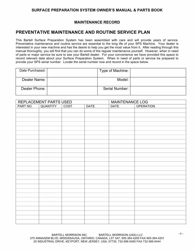
MAINTENANCE RECORD PREVENTATIVE MAINTENANCE AND ROUTINE SERVICE PLAN This Bartell Surface Preparation System has been assembled with care and will provide years of service. Preventative maintenance and routine service are essential to the long life of your SPS Machine. Your dealer is interested in your new machine and has the desire to help you get the most value from it. After reading through this manual thoroughly, you will find that you can do some of the regular maintenance yourself. However, when in need of parts or major service be sure to see your Bartell dealer. For your convenience we have provided this space to record relevant data about your Surface Preparation System. When in need of parts or service be prepared to provide your SPS serial number. Locate the serial number now and record in the space below.
Date Purchased:
Type of Machine:
Dealer Name:
Model:
Dealer Phone:
Serial Number:
11BREPLACEMENT PARTS USED 12BMAINTENANCE LOG PART NO. QUANTITY COST DATE DATE OPERATION
SURFACE PREPARATION SYSTEM OWNER’S MANUAL & PARTS BOOK
BARTELL MORRISON INC. BARTELL MORRISON (USA) LLC 375 ANNAGEM BLVD, MISSISSAUGA, ONTARIO, CANADA, L5T 3A7, 905-364-4200 FAX 905-364-4201
25 INDUSTRIAL DRIVE, KEYPORT, NEW JERSEY, USA, 07735, 732-566-5400 FAX 732-566-5444
- 7 -
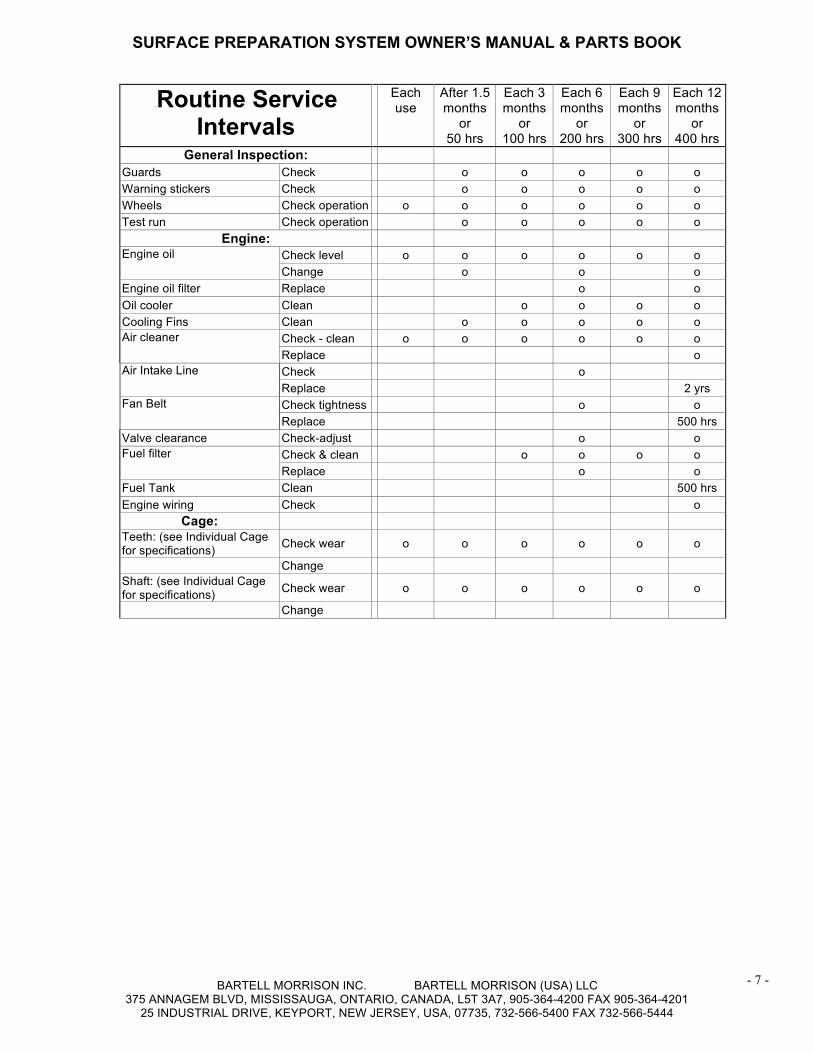
13BRoutine Service Intervals
Each use
After 1.5 months
or 50 hrs
Each 3 months
or 100 hrs
Each 6 months
or 200 hrs
Each 9 months
or 300 hrs
Each 12 months
or 400 hrs
General Inspection: Guards Check o o o o o Warning stickers Check o o o o o Wheels Check operation o o o o o o Test run Check operation o o o o o
Engine: Engine oil Check level o o o o o o
Change o o o Engine oil filter Replace o o Oil cooler Clean o o o o Cooling Fins Clean o o o o o Air cleaner Check - clean o o o o o o
Replace o Air Intake Line Check o
Replace 2 yrs Fan Belt Check tightness o o
Replace 500 hrs Valve clearance Check-adjust o o Fuel filter Check & clean o o o o
Replace o o Fuel Tank Clean 500 hrs Engine wiring Check o
Cage: Teeth: (see Individual Cage for specifications) Check wear o o o o o o
Change Shaft: (see Individual Cage for specifications) Check wear o o o o o o
Change
SURFACE PREPARATION SYSTEM OWNER’S MANUAL & PARTS BOOK
BARTELL MORRISON INC. BARTELL MORRISON (USA) LLC 375 ANNAGEM BLVD, MISSISSAUGA, ONTARIO, CANADA, L5T 3A7, 905-364-4200 FAX 905-364-4201
25 INDUSTRIAL DRIVE, KEYPORT, NEW JERSEY, USA, 07735, 732-566-5400 FAX 732-566-5444
- 8 -
Routine Service Intervals The machine is generally run in very dusty conditions. Engine life will be extended by maintaining a clean engine and using a proper dust control system. Keep the air filter clean at all times. Wash the element in a non-oil based solvent. Squeeze out any residue and allow the filter to dry before reinstalling the air cleaner. Some general maintenance guidelines will extend the useful life of your trowel. • The initial service for your SPS Machine should be performed after 25 hours of use, at which time your
mechanic (or authorized repair shop) should complete all of the recommended checks in the schedule above. The chart on page 6 (six) is handy for keeping a record of the maintenance performed and the parts used for servicing your trowel.
• Regular service according to the schedule above will prolong the life of the surface preparation system and prevent expensive repairs.
• Keeping your SPS Machine clean and free from debris is the single most important regular maintenance operation, over and above the checks in the service schedule above, that can be performed. After each use your SPS Machine should be cleaned to remove any dust and debris from the undercarriage and surrounding components. Use of a power washer will make clean up quick and easy, especially if a non-stick coating was applied prior to use.
• In the Service Schedule above, items that should be checked, replaced or adjusted are indicated by “o” in the appropriate column. Not all SPS models include the same features and options and as such not all service operations may have to be performed. For ease of recording place a checkmark (√) through the “o” when the item is complete. If an item is not required or not completed place an “x” through the “o” in the box.
• All SPS Machines have governed engine speed of 3600 rpm. See engine manufacturer’s manual for exact specifications. Care should be used when making any adjustments to the SPS Machine not to change the governed speed. Running the engine at lower rpm’s will cause the cutters to skip over the surface rather than cut into it. It will create excessive “out-of-synch” vibrations resulting in poor surface results, handling, maneuverability, and discomfort to the operator.
• Failure to have your Surface Preparation System regularly serviced and properly maintained in accordance with the manufacturer’s instructions will lead to premature failure and void the warranty.
SURFACE PREPARATION SYSTEM OWNER’S MANUAL & PARTS BOOK
BARTELL MORRISON INC. BARTELL MORRISON (USA) LLC 375 ANNAGEM BLVD, MISSISSAUGA, ONTARIO, CANADA, L5T 3A7, 905-364-4200 FAX 905-364-4201
25 INDUSTRIAL DRIVE, KEYPORT, NEW JERSEY, USA, 07735, 732-566-5400 FAX 732-566-5444
- 9 -
2BFOREWORD It is important that the following information be read carefully in order that the operational characteristics and performance of the Bartell Surface Preparation System be fully understood. Proper adherence to operation and maintenance procedures will ensure long life and top performance of your equipment. SAFETY PRECAUTIONS • Always keep unauthorized, inexperienced, untrained
people away from this machine. • Rotating and moving parts will cause injury if
contacted. Make sure guards are in place. Keep hands and feet away from moving parts.
• Fuel the machine only when the engine is stopped, using all necessary safety precautions.
• The engine must always be stopped before attempting any repair or adjustments. Ignition switch should be off. Danger: Never operate the machine in an explosive atmosphere, near combustible materials or where ventilation does not clear exhaust fumes. Repair fuel leaks immediately. Refer to your engine owner’s manual for more safety instructions.
• Be careful not to come in contact with the muffler when the engine is hot, serious burns may result!
• Do not run the air motor without sufficient oil in the lubrication system. The lubricant levels should be checked regularly on gas and air powered units. Refer to manufacturer’s manual for amounts.
• Before starting you SPS machine, always raise the cutter cage assembly using the hand knob adjustment, so that cutters do not contact the surface.
OPERATING PRINCIPLE The SPS employs a belt-pulley drive, for the cages which contact the surfaces to be prepared. The hand knob adjustment allows the cages to be raised or lowered as necessary to perform efficient work. The vibration isolators on the bridge make it easier on the operator and the machine, while the hexagonal drive bearing produces more positive cutter engagement. A dust control vacuum should be used to provide a clean work area. The SPS Machine is designed to run at an engine speed (engine take off shaft) of 3600 rpm. (normally considered full throttle). Never force the cutter head into the surface to a point where the machine starts to bounce. This will minimize results and do more damage to the machine than the work surface. Let the cutters do the work, but make sure you have the best cutter/cage assembly for the job.
WORKING WITH THE SPS We have found that working the machine in a figure “8” pattern, when milling misaligned concrete slabs or joints will produce more aggressive removal of material. The cutters will work against the cut and tend to produce more consistent and faster removal of material. Moving the machine in a straight line tends to create grooves that the cutters will follow. The Tungsten Carbide Tipped cutters produce the longest life in milling applications and should be considered as the best choice, in spite of the higher initial costs. Your time is valuable and when you have to change cutters or even cutter assemblies you are not using the machine to make money.
When using the SPS to mill concrete, work the left side or belt guard side, riding on the high side of the cut, if possible. This will avoid the possibility of the drive pulley engaging the work surface. Regularly check that the drive pulley is aligned properly and secured to the drive shaft. When using any Cutter Cage Assemblies, there will be variations in the floor. The depth of cut should be adjusted with the hand knob to maintain an equal penetration of the work surface.
Grooving set ups are possible with the SPS in as many configurations as you need. The normal set up of the R123 uses cutters spaced with 1” centers, braced by tension springs. They could also be set up with other centers, but bear in mind that they must always be tensioned to maintain the path you require. Checkerboard effects are possible by working the machine at 90° to the path first established.
When using the Edger attachment for crack chasing, try the following method. Mark the front of the edger with a chalk guide line to correspond to the starting point of the crack. Lower the head into the crack and push the machine forward along the fault line using the chalk mark as the steering guide. Using carbides gives the longest life, but B-2 and B-3 cutters may also be used in the set up. Always tension the cutters in the cage with spring load to maintain a consistent path. CUTTER LIFE How long cutters and cages last on a particular job is a difficult thing to predict. There are a number of variables involved which must always be considered. How old/hard is the material you are working with? Are there any hardeners on additives that will slow you down? Are you forcing the cage into the surface? Is the equipment properly maintained? Is the operator familiar with the machine and its capabilities? Do you have the proper cutter/cage set up for the application? There are additional cutters and cages to those below, but this is a fair representation of estimated rates for production and cutter life. We preset them as a guide only, due to variables such as above.
SURFACE PREPARATION SYSTEM OWNER’S MANUAL & PARTS BOOK
BARTELL MORRISON INC. BARTELL MORRISON (USA) LLC 375 ANNAGEM BLVD, MISSISSAUGA, ONTARIO, CANADA, L5T 3A7, 905-364-4200 FAX 905-364-4201
25 INDUSTRIAL DRIVE, KEYPORT, NEW JERSEY, USA, 07735, 732-566-5400 FAX 732-566-5444
- 10 -
GENERAL APPLICATION ADHESIVES – CARPET R120 (B-1 Cutters) For the removal of most carpet adhesives. Estimated Production Rates: 100-300 sq.ft/hr Estimated Cutter Life: 1200-1500 sq.ft ADHESIVES – TILE R138 (A-3, B-3 Cutters) For the removal of most tile adhesives. Estimated Production Rates: 100-250 sq.ft/hr Estimated Cutter Life: 1200-1500 sq.ft CONCRETE GRINDING R150, R151, or R152 (Carbide Cutters) For the smoothing of rough concrete and/or grinding of high spots. Estimated Production Rates: 200-500 sq.ft/hr Estimated Cutter Life: 3000-6000 sq.ft
CONCRETE SCARIFYING/GRINDING R134 or R139 (Tungsten Carbide Tipped Cutters) For preparation of concrete prior to the application of coatings or concrete overlay (1/8” depth of cut per pass.). Estimated Production Rates: 200-400 sq.ft/hr Estimated Cutter Life: 8000-15,000 sq.ft LINE REMOVAL R132 (B-2) For the removal of painted lines from concrete or asphalt. Estimated Production Rates: 10-20 linear ft/min Estimated Cutter Life: 800-2000 linear ft. LINE REMOVAL – THERMOPLASTIC R143 (B-3) For the removal of thermoplastic based paints from concrete or asphalt. Estimated Production Rates: 10-20 linear ft/min Estimated Cutter Life: 800-1200 linear ft.
TYPICAL APPLICATIONS • Asphalt leveling and grooving • Carpet backing removal • Coating removal • Concrete grinding • Concrete & steel surface preparation • Concrete grooving • Epoxy removal • Expansion joint leveling • Floor cleaning steel & concrete • Glue/adhesive removal • Milling joints
TYPICAL APPLICATIONS (Cont.) • Non-slip removal • Paint removal • Steel de-scaling • Traffic line removal • Wheelchair ramp leveling
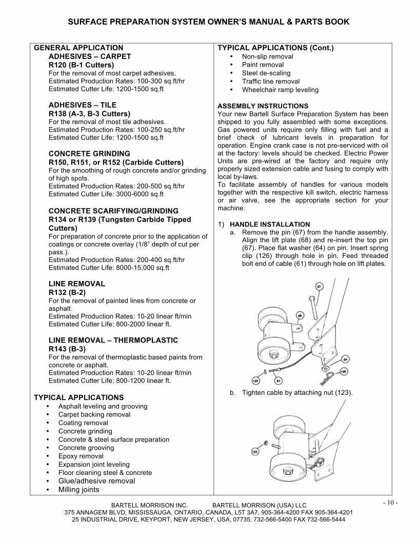
ASSEMBLY INSTRUCTIONS Your new Bartell Surface Preparation System has been shipped to you fully assembled with some exceptions. Gas powered units require only filling with fuel and a brief check of lubricant levels in preparation for operation. Engine crank case is not pre-serviced with oil at the factory: levels should be checked. Electric Power Units are pre-wired at the factory and require only properly sized extension cable and fusing to comply with local by-laws. To facilitate assembly of handles for various models together with the respective kill switch, electric harness or air valve, see the appropriate section for your machine. 1) HANDLE INSTALLATION
a. Remove the pin (67) from the handle assembly. Align the lift plate (68) and re-insert the top pin (67). Place flat washer (64) on pin. Insert spring clip (126) through hole in pin. Feed threaded bolt end of cable (61) through hole on lift plates.
b. Tighten cable by attaching nut (123).
SURFACE PREPARATION SYSTEM OWNER’S MANUAL & PARTS BOOK
BARTELL MORRISON INC. BARTELL MORRISON (USA) LLC 375 ANNAGEM BLVD, MISSISSAUGA, ONTARIO, CANADA, L5T 3A7, 905-364-4200 FAX 905-364-4201
25 INDUSTRIAL DRIVE, KEYPORT, NEW JERSEY, USA, 07735, 732-566-5400 FAX 732-566-5444
- 11 -
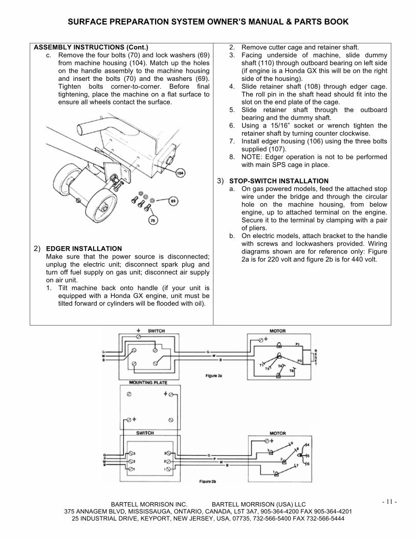
ASSEMBLY INSTRUCTIONS (Cont.) c. Remove the four bolts (70) and lock washers (69)
from machine housing (104). Match up the holes on the handle assembly to the machine housing and insert the bolts (70) and the washers (69). Tighten bolts corner-to-corner. Before final tightening, place the machine on a flat surface to ensure all wheels contact the surface.
2) EDGER INSTALLATION
Make sure that the power source is disconnected; unplug the electric unit; disconnect spark plug and turn off fuel supply on gas unit; disconnect air supply on air unit. 1. Tilt machine back onto handle (if your unit is
equipped with a Honda GX engine, unit must be tilted forward or cylinders will be flooded with oil).
2. Remove cutter cage and retainer shaft. 3. Facing underside of machine, slide dummy
shaft (110) through outboard bearing on left side (if engine is a Honda GX this will be on the right side of the housing).
4. Slide retainer shaft (108) through edger cage. The roll pin in the shaft head should fit into the slot on the end plate of the cage.
5. Slide retainer shaft through the outboard bearing and the dummy shaft.
6. Using a 15/16” socket or wrench tighten the retainer shaft by turning counter clockwise.
7. Install edger housing (106) using the three bolts supplied (107).
8. NOTE: Edger operation is not to be performed with main SPS cage in place.
3) STOP-SWITCH INSTALLATION
a. On gas powered models, feed the attached stop wire under the bridge and through the circular hole on the machine housing, from below engine, up to attached terminal on the engine. Secure it to the terminal by clamping with a pair of pliers.
b. On electric models, attach bracket to the handle with screws and lockwashers provided. Wiring diagrams shown are for reference only: Figure 2a is for 220 volt and figure 2b is for 440 volt.
SURFACE PREPARATION SYSTEM OWNER’S MANUAL & PARTS BOOK
BARTELL MORRISON INC. BARTELL MORRISON (USA) LLC 375 ANNAGEM BLVD, MISSISSAUGA, ONTARIO, CANADA, L5T 3A7, 905-364-4200 FAX 905-364-4201
25 INDUSTRIAL DRIVE, KEYPORT, NEW JERSEY, USA, 07735, 732-566-5400 FAX 732-566-5444
- 12 -
STARTING PROCEDURE (GAS OPERATED): 14B* WARM CLIMATE IMPORTANT: Set the machine in an upright position and adjust the cutter cage to maximum height by turning the height adjustment knob (51) to its farthest position. (This will ensure clearance for the rotation cage.)
Open fuel valve on gas tank. Set throttle lever to “Fast” idle position, set choke to closed position, start engine. Open choke slightly to prevent flooding. Move to “Open” or “Run” position when engine is warm, increase throttle to maximum operation position (3600 rpm). STARTING PROCEDURE (GAS OPERATED): * COLD CLIMATE With the machine in upright position, follow same procedure as above but allow longer warm-up period – 3 to 5 minutes. In cold weather, oil is much heavier to move and requires more time to work its way into the moving parts. If maximum power is not attained, allow further warm-up time. Fill fuel tank with clean gasoline, use safety approved gas containers. DO NOT MIX OIL WITH GASOLINE (USE UNLEADED GAS ONLY.) STARTING PROCEDURE (ELECTRIC): With the cage in maximum raised position, plug in power cord to power source. Press the start button. Run-in for two (2) minutes. Press the stop button, then re-start. Ensure your cable is of sufficient size to run the motor properly. (14/3 type S for 220 volt; 16/3 type S for 440 volt.) STARTING PROCEDURE (AIR): With cage in maximum raised position, attach air supply (minimum 90 C.F.M. at 90 P.S.I.) turn quick opening valve on. Run in for two (2) minutes. Turn off valve, then re-start. The air regulator is equipped with a pressure gauge. The recommended operating pressure is 90 P.S.I. at 90 C.F.M.; however when the unit is running with no load (cutters not engaged) the gauge will read 40 P.S.I. When the cutters are engaged the indicator needle should rise to 90 P.S.I. STOPPING PROCEDURE: With machine in upright position, adjust the cutter cage to maximum height by turning the height adjustment knob (51) to its farthest position. (This ensures clearance for the rotating cage.) GAS UNIT – Stop engine by depressing kill switch button
(53) located at top of handle. AIR UNIT – Turn off air supply valve (25). ELECTRIC UNIT – Turn off switch on handle (11).
MAINTENANCE The SPS Machine is generally run in very dusty conditions. Engine life will be extended by maintaining a clean engine and using a dust control system. See owners manual for a complete maintenance schedule.
AIR CLEANER (GAS UNIT) - Keep air filter clean at all times. Wash away dust and debris using a non-oil based cleaning solvent. Let the filter dry before re-installing.
MAINTENANCE (Cont.)
LUBRICATION – Always check engine oil regularly. Use proper engine oil as recommended. See chart below. Fill crankcase to levels as recommended in manufacture’s engine manual. SPARK PLUG (GAS UNIT)– Check and clean spark plugs regularly. A fouled, dirty or carboned spark plug causes hard starting and poor engine performance. Set spark plug gap to recommended clearance. Refer to engine manual. BELT TENSION – IMPORTANT! If there is excessive belt play, there will be a decrease in the cutting/grinding action, which could cause cage and machine damage. The normal belt play should be 3/8” to 1/2” which is attained by depressing the top section of the belt at the belt guard mounting bracket location. When adjusting the belt make sure that the drive pulley is in alignment with cage pulley. Tighten all engine mount bolts, adjust the two engine-stop bolts, and tighten lock nuts. DRIVE SHAFT – Keep a coating of grease on the drive shaft and threads for easy installation or removal and longer bushing life. SPOT CHECKS – Perform as required. Machine should be inspected with ignition in “OFF” position or power disconnected. Do not perform inspections while machine is running.
• Check all fasteners for tightness – machine is subject to vibration.
• Check “V” belt for wear; adjust or replace as required.
• Check that wheels are clean and rotation freely.
• Check that inside of housing is clean; remove any build-up as required.
• Check that pulleys are aligned properly to ensure that “V” belt is running true. (i.e. not at an angle.)
SURFACE PREPARATION SYSTEM OWNER’S MANUAL & PARTS BOOK
BARTELL MORRISON INC. BARTELL MORRISON (USA) LLC 375 ANNAGEM BLVD, MISSISSAUGA, ONTARIO, CANADA, L5T 3A7, 905-364-4200 FAX 905-364-4201
25 INDUSTRIAL DRIVE, KEYPORT, NEW JERSEY, USA, 07735, 732-566-5400 FAX 732-566-5444
- 13 -
BEARING REPLACEMENT PROCEDURES IMPORTANT: Disengage power supply. Do not attempt replacement while machine is operable. A) 3BSEALED BEARING REPLACEMENT – OUTBOARD
SIDE 4BRemove drive shaft and cutter cage assembly as per cutter change procedure below. Loosen and remove bearing block flange by removing screws and lockwashers. Using a soft drift, drive out and remove old bearing. Clean parts which will be re-used. Carefully press new bearing into flange. Take extreme care to maintain aligned installation. Do not press sleeve into position if misaligned. Mount bearing block to side of housing and tighten bolts when bearing block is in a free spin position.
B) 5BBEARING REPLACEMENT – DRIVER OR “V”
BELT SIDE Remove belt guard and “V” belt. Loosen two set screws, remove pulley and remove key. Remove bearing block assembly by removing screws and lock washers. Remove snap ring and slip ring. Using a soft drift, drive out spindle. Take care not to burr or flare spindle. Remove cover plate being certain the plate fits flush. Carefully press new bearing into block, clean and install bearing cover plate. Press drive spindle into block. Install slip ring and snap ring. Center and install spindle assembly to housing. Re-install pulley and key. Ensure pulley butts flush against shoulder or spindle. NOTE: When removing spindle or sleeve, care must be taken not to damage or distort these parts. A soft drift is recommended to prevent damage.
CUTTER CAGE REMOVAL & CUTTER CHANGE To remove the cutter cage from the machine. 1. Make sure that the power source is disconnected.
With gas models turn off fuel supply to engine and disconnect sparkplug; unplug electric unit; disconnect air supply on air unit.
2. Tilt machine back onto the handle. (If your unit is equipped with a Honda GX engine, unit must be tilted forward to change cutters or cylinders will be flooded with oil).
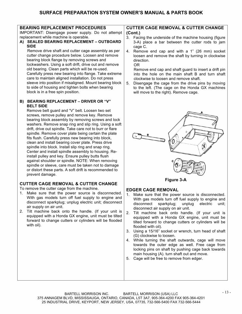
CUTTER CAGE REMOVAL & CUTTER CHANGE (Cont.) 3. Facing the underside of the machine housing (figure
3-A) place a bar between the cutter rods to jam cage C.
4. Remove end cap and with a 1” (26 mm) socket loosen and remove the shaft by turning in clockwise direction. OR Remove end cap and shaft guard to insert a drift pin into the hole on the main shaft B and turn shaft clockwise to loosen and remove shaft.
5. Disengage the cage from the drive pins by moving to the left. (The cage on the Honda GX machines will move to the right). Remove cage.
Figure 3-A EDGER CAGE REMOVAL 1. Make sure that the power source is disconnected.
With gas models turn off fuel supply to engine and disconnect sparkplug; unplug electric unit; disconnect air supply on air unit.
2. Tilt machine back onto handle. (If your unit is equipped with a Honda GX engine, unit must be tilted forward to change cutters or cylinders will be flooded with oil).
3. Using a 15/16” socket or wrench, turn head of shaft (G) clockwise to loosen.
4. While turning the shaft outwards, cage will move towards the outer edge as well. Free cage from locking pins on shaft by pushing cage back towards main housing (A). turn shaft out and move.
5. Cage will be free to remove from edger.
SURFACE PREPARATION SYSTEM OWNER’S MANUAL & PARTS BOOK
BARTELL MORRISON INC. BARTELL MORRISON (USA) LLC 375 ANNAGEM BLVD, MISSISSAUGA, ONTARIO, CANADA, L5T 3A7, 905-364-4200 FAX 905-364-4201
25 INDUSTRIAL DRIVE, KEYPORT, NEW JERSEY, USA, 07735, 732-566-5400 FAX 732-566-5444
- 14 -
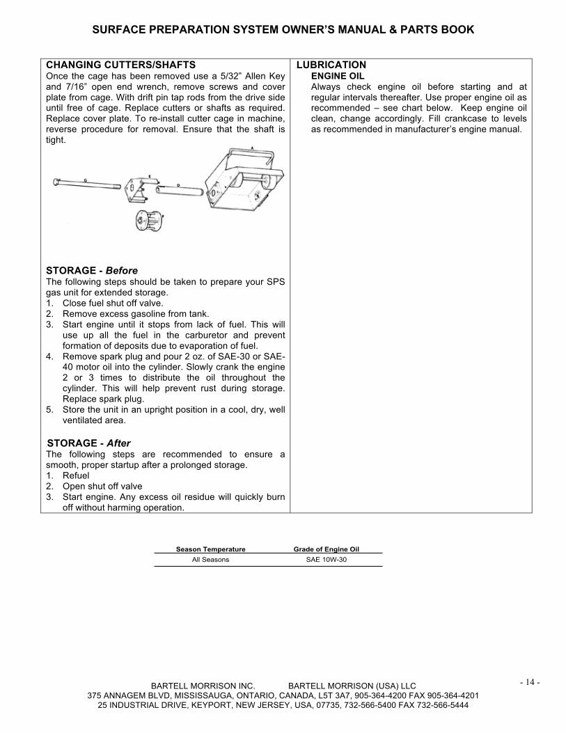
CHANGING CUTTERS/SHAFTS Once the cage has been removed use a 5/32” Allen Key and 7/16” open end wrench, remove screws and cover plate from cage. With drift pin tap rods from the drive side until free of cage. Replace cutters or shafts as required. Replace cover plate. To re-install cutter cage in machine, reverse procedure for removal. Ensure that the shaft is tight.
STORAGE - Before The following steps should be taken to prepare your SPS gas unit for extended storage. 1. Close fuel shut off valve. 2. Remove excess gasoline from tank. 3. Start engine until it stops from lack of fuel. This will
use up all the fuel in the carburetor and prevent formation of deposits due to evaporation of fuel.
4. Remove spark plug and pour 2 oz. of SAE-30 or SAE-40 motor oil into the cylinder. Slowly crank the engine 2 or 3 times to distribute the oil throughout the cylinder. This will help prevent rust during storage. Replace spark plug.
5. Store the unit in an upright position in a cool, dry, well ventilated area.
6BSTORAGE - After The following steps are recommended to ensure a smooth, proper startup after a prolonged storage. 1. Refuel 2. Open shut off valve 3. Start engine. Any excess oil residue will quickly burn
off without harming operation.
7BLUBRICATION ENGINE OIL Always check engine oil before starting and at regular intervals thereafter. Use proper engine oil as recommended – see chart below. Keep engine oil clean, change accordingly. Fill crankcase to levels as recommended in manufacturer’s engine manual.
Season Temperature Grade of Engine OilAll Seasons SAE 10W-30

SURFACE PREPARATION SYSTEM OWNER’S MANUAL & PARTS BOOK
BARTELL MORRISON INC. BARTELL MORRISON (USA) LLC 375 ANNAGEM BLVD, MISSISSAUGA, ONTARIO, CANADA, L5T 3A7, 905-364-4200 FAX 905-364-4201
25 INDUSTRIAL DRIVE, KEYPORT, NEW JERSEY, USA, 07735, 732-566-5400 FAX 732-566-5444
- 15 -
8BASSEMBLY DRAWIASSEMBLY DRAWINGS AND PARTS NGS AND PARTS LISTLIST
U
SURFACE PREPARATION SYSTEM OWNER’S MANUAL & PARTS BOOK
BARTELL MORRISON INC. BARTELL MORRISON (USA) LLC 375 ANNAGEM BLVD, MISSISSAUGA, ONTARIO, CANADA, L5T 3A7, 905-364-4200 FAX 905-364-4201
25 INDUSTRIAL DRIVE, KEYPORT, NEW JERSEY, USA, 07735, 732-566-5400 FAX 732-566-5444
- 16 -
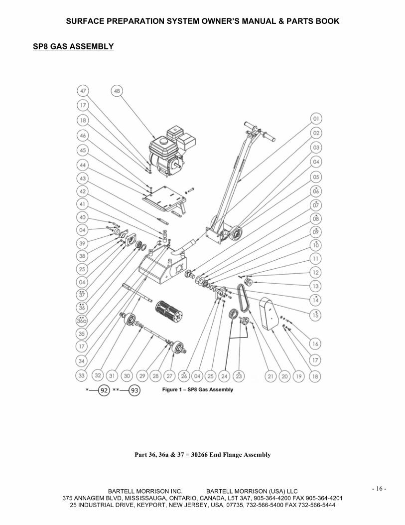
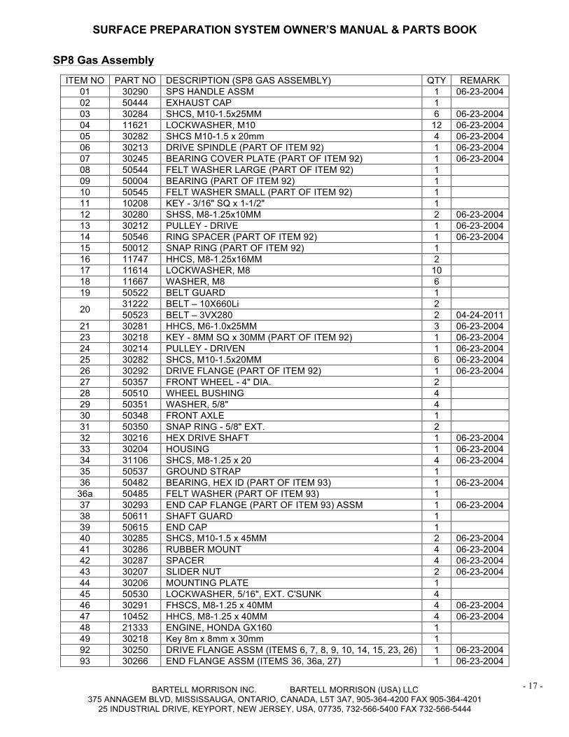
SP8 GAS ASSEMBLY
Part 36, 36a & 37 = 30266 End Flange Assembly
SURFACE PREPARATION SYSTEM OWNER’S MANUAL & PARTS BOOK
BARTELL MORRISON INC. BARTELL MORRISON (USA) LLC 375 ANNAGEM BLVD, MISSISSAUGA, ONTARIO, CANADA, L5T 3A7, 905-364-4200 FAX 905-364-4201
25 INDUSTRIAL DRIVE, KEYPORT, NEW JERSEY, USA, 07735, 732-566-5400 FAX 732-566-5444
- 17 -
ITEM NO PART NO DESCRIPTION (SP8 GAS ASSEMBLY) QTY REMARK 01 30290 SPS HANDLE ASSM 1 06-23-2004 02 50444 EXHAUST CAP 1 03 30284 SHCS, M10-1.5x25MM 6 06-23-2004 04 11621 LOCKWASHER, M10 12 06-23-2004 05 30282 SHCS M10-1.5 x 20mm 4 06-23-2004 06 30213 DRIVE SPINDLE (PART OF ITEM 92) 1 06-23-2004 07 30245 BEARING COVER PLATE (PART OF ITEM 92) 1 06-23-2004 08 50544 FELT WASHER LARGE (PART OF ITEM 92) 1 09 50004 BEARING (PART OF ITEM 92) 1 10 50545 FELT WASHER SMALL (PART OF ITEM 92) 1 11 10208 KEY - 3/16" SQ x 1-1/2" 1 12 30280 SHSS, M8-1.25x10MM 2 06-23-2004 13 30212 PULLEY - DRIVE 1 06-23-2004 14 50546 RING SPACER (PART OF ITEM 92) 1 06-23-2004 15 50012 SNAP RING (PART OF ITEM 92) 1 16 11747 HHCS, M8-1.25x16MM 2 17 11614 LOCKWASHER, M8 10 18 11667 WASHER, M8 6 19 50522 BELT GUARD 1
20 31222 BELT – 10X660Li 2 50523 BELT – 3VX280 2 04-24-2011
21 30281 HHCS, M6-1.0x25MM 3 06-23-2004 23 30218 KEY - 8MM SQ x 30MM (PART OF ITEM 92) 1 06-23-2004 24 30214 PULLEY - DRIVEN 1 06-23-2004 25 30282 SHCS, M10-1.5x20MM 6 06-23-2004 26 30292 DRIVE FLANGE (PART OF ITEM 92) 1 06-23-2004 27 50357 FRONT WHEEL - 4" DIA. 2 28 50510 WHEEL BUSHING 4 29 50351 WASHER, 5/8" 4 30 50348 FRONT AXLE 1 31 50350 SNAP RING - 5/8" EXT. 2 32 30216 HEX DRIVE SHAFT 1 06-23-2004 33 30204 HOUSING 1 06-23-2004 34 31106 SHCS, M8-1.25 x 20 4 06-23-2004 35 50537 GROUND STRAP 1 36 50482 BEARING, HEX ID (PART OF ITEM 93) 1 06-23-2004
36a 50485 FELT WASHER (PART OF ITEM 93) 1 37 30293 END CAP FLANGE (PART OF ITEM 93) ASSM 1 06-23-2004 38 50611 SHAFT GUARD 1 39 50615 END CAP 1 40 30285 SHCS, M10-1.5 x 45MM 2 06-23-2004 41 30286 RUBBER MOUNT 4 06-23-2004 42 30287 SPACER 4 06-23-2004 43 30207 SLIDER NUT 2 06-23-2004 44 30206 MOUNTING PLATE 1 45 50530 LOCKWASHER, 5/16", EXT. C'SUNK 4 46 30291 FHSCS, M8-1.25 x 40MM 4 06-23-2004 47 10452 HHCS, M8-1.25 x 40MM 4 06-23-2004 48 21333 ENGINE, HONDA GX160 1 49 30218 Key 8m x 8mm x 30mm 1 92 30250 DRIVE FLANGE ASSM (ITEMS 6, 7, 8, 9, 10, 14, 15, 23, 26) 1 06-23-2004 93 30266 END FLANGE ASSM (ITEMS 36, 36a, 27) 1 06-23-2004
SP8 Gas Assembly
SURFACE PREPARATION SYSTEM OWNER’S MANUAL & PARTS BOOK
BARTELL MORRISON INC. BARTELL MORRISON (USA) LLC 375 ANNAGEM BLVD, MISSISSAUGA, ONTARIO, CANADA, L5T 3A7, 905-364-4200 FAX 905-364-4201
25 INDUSTRIAL DRIVE, KEYPORT, NEW JERSEY, USA, 07735, 732-566-5400 FAX 732-566-5444
- 18 -
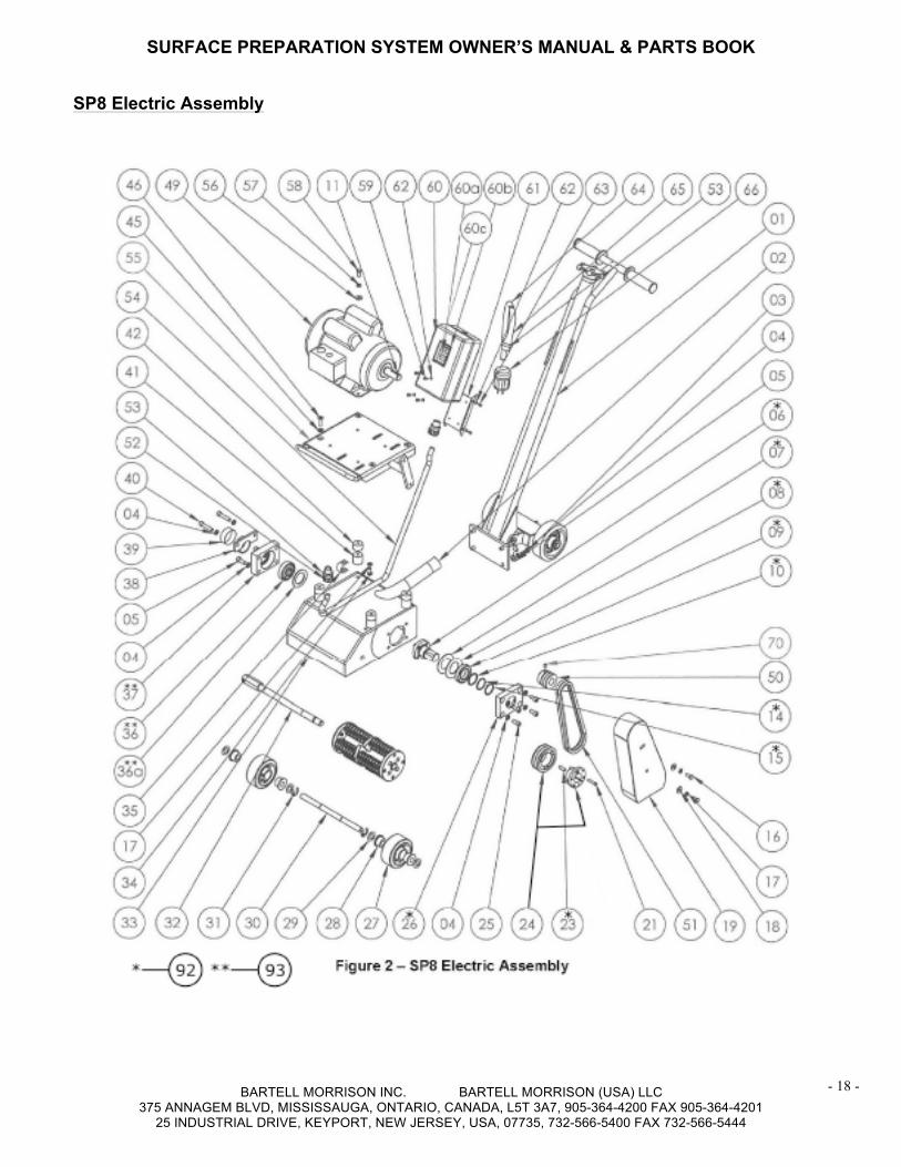
SP8 Electric Assembly
SURFACE PREPARATION SYSTEM OWNER’S MANUAL & PARTS BOOK
BARTELL MORRISON INC. BARTELL MORRISON (USA) LLC 375 ANNAGEM BLVD, MISSISSAUGA, ONTARIO, CANADA, L5T 3A7, 905-364-4200 FAX 905-364-4201
25 INDUSTRIAL DRIVE, KEYPORT, NEW JERSEY, USA, 07735, 732-566-5400 FAX 732-566-5444
- 19 -
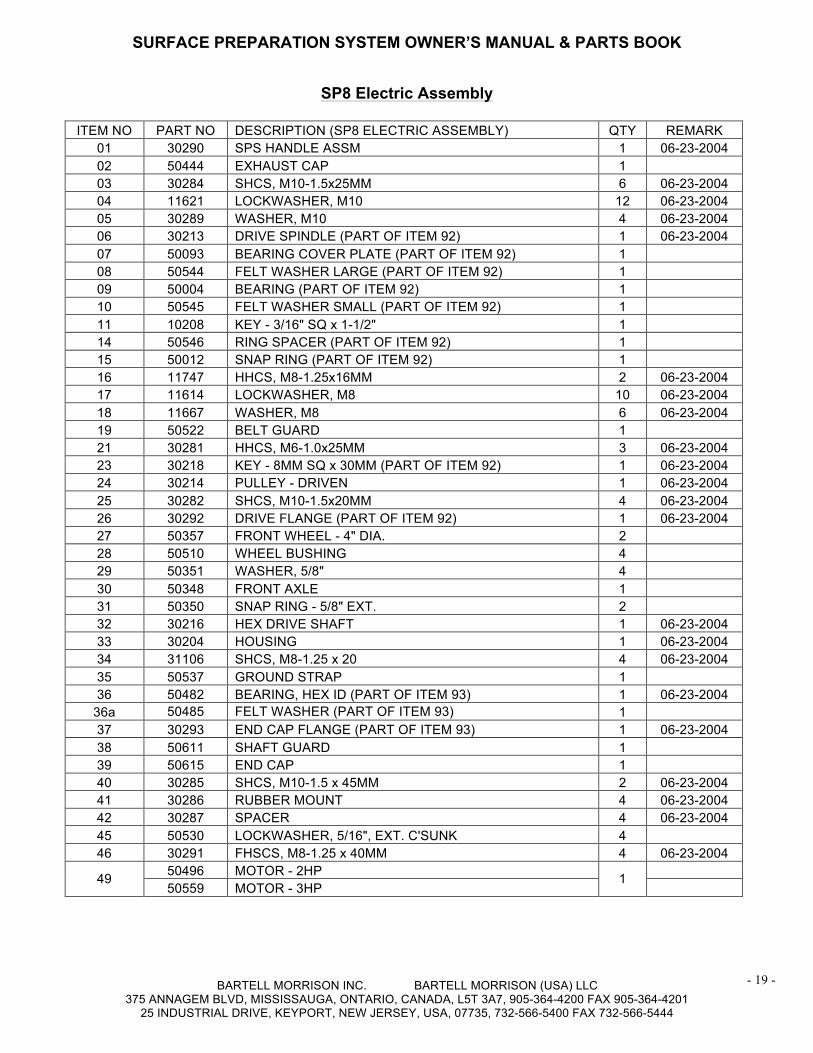
SP8 Electric Assembly
ITEM NO PART NO DESCRIPTION (SP8 ELECTRIC ASSEMBLY) QTY REMARK 01 30290 SPS HANDLE ASSM 1 06-23-2004 02 50444 EXHAUST CAP 1 03 30284 SHCS, M10-1.5x25MM 6 06-23-2004 04 11621 LOCKWASHER, M10 12 06-23-2004 05 30289 WASHER, M10 4 06-23-2004 06 30213 DRIVE SPINDLE (PART OF ITEM 92) 1 06-23-2004 07 50093 BEARING COVER PLATE (PART OF ITEM 92) 1 08 50544 FELT WASHER LARGE (PART OF ITEM 92) 1 09 50004 BEARING (PART OF ITEM 92) 1 10 50545 FELT WASHER SMALL (PART OF ITEM 92) 1 11 10208 KEY - 3/16" SQ x 1-1/2" 1 14 50546 RING SPACER (PART OF ITEM 92) 1 15 50012 SNAP RING (PART OF ITEM 92) 1 16 11747 HHCS, M8-1.25x16MM 2 06-23-2004 17 11614 LOCKWASHER, M8 10 06-23-2004 18 11667 WASHER, M8 6 06-23-2004 19 50522 BELT GUARD 1 21 30281 HHCS, M6-1.0x25MM 3 06-23-2004 23 30218 KEY - 8MM SQ x 30MM (PART OF ITEM 92) 1 06-23-2004 24 30214 PULLEY - DRIVEN 1 06-23-2004 25 30282 SHCS, M10-1.5x20MM 4 06-23-2004 26 30292 DRIVE FLANGE (PART OF ITEM 92) 1 06-23-2004 27 50357 FRONT WHEEL - 4" DIA. 2 28 50510 WHEEL BUSHING 4 29 50351 WASHER, 5/8" 4 30 50348 FRONT AXLE 1 31 50350 SNAP RING - 5/8" EXT. 2 32 30216 HEX DRIVE SHAFT 1 06-23-2004 33 30204 HOUSING 1 06-23-2004 34 31106 SHCS, M8-1.25 x 20 4 06-23-2004 35 50537 GROUND STRAP 1 36 50482 BEARING, HEX ID (PART OF ITEM 93) 1 06-23-2004
36a 50485 FELT WASHER (PART OF ITEM 93) 1 37 30293 END CAP FLANGE (PART OF ITEM 93) 1 06-23-2004 38 50611 SHAFT GUARD 1 39 50615 END CAP 1 40 30285 SHCS, M10-1.5 x 45MM 2 06-23-2004 41 30286 RUBBER MOUNT 4 06-23-2004 42 30287 SPACER 4 06-23-2004 45 50530 LOCKWASHER, 5/16", EXT. C'SUNK 4 46 30291 FHSCS, M8-1.25 x 40MM 4 06-23-2004
49 50496 MOTOR - 2HP 1 50559 MOTOR - 3HP
SURFACE PREPARATION SYSTEM OWNER’S MANUAL & PARTS BOOK
BARTELL MORRISON INC. BARTELL MORRISON (USA) LLC 375 ANNAGEM BLVD, MISSISSAUGA, ONTARIO, CANADA, L5T 3A7, 905-364-4200 FAX 905-364-4201
25 INDUSTRIAL DRIVE, KEYPORT, NEW JERSEY, USA, 07735, 732-566-5400 FAX 732-566-5444
- 20 -
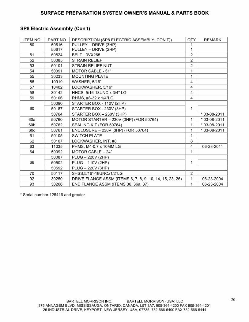
SP8 Electric Assembly (Con’t)
ITEM NO PART NO DESCRIPTION (SP8 ELECTRIC ASSEMBLY, CON’T)) QTY REMARK 50
50616 50617
PULLEY – DRIVE (3HP) PULLEY – DRIVE (2HP)
1 1
51 50524 BELT - 3VX265 2 52 50085 STRAIN RELIEF 2 53 50101 STRAIN RELIEF NUT 2 54 50091 MOTOR CABLE - 51" 1 55 30233 MOUNTING PLATE 1 56 10919 WASHER, 5/16" 4 57 10402 LOCKWASHER, 5/16" 4 58 30142 HHCS, 5/16-18UNC x 3/4" LG 4 59 50106 RHMS, #8-32 x 1/4"LG 4
60 50090 STARTER BOX - 110V (2HP)
1
50187 STARTER BOX - 230V (3HP) 50764 STARTER BOX – 230V (3HP) * 03-08-2011
60a 50760 MOTOR STARTER – 230V (3HP) (FOR 50764) 1 * 03-08-2011 60b 50762 SEALING KIT (FOR 50764) 1 * 03-08-2011 60c 50761 ENCLOSURE – 230V (3HP) (FOR 50764) 1 * 03-08-2011 61 50105 SWITCH PLATE 1 62 50107 LOCKWASHER, INT. #8 8 63 11035 PHMS, M4-0.7 x 10MM LG 4 06-28-2011 64 50092 MOTOR CABLE – 24” 1
66 50087 PLUG – 220V (2HP)
1
50502 PLUG – 110V (2HP) 50592 PLUG – 220V (3HP)
70 50117 SHSS,5/16”-18UNCx1/2”LG 2 92 30250 DRIVE FLANGE ASSM (ITEMS 6, 7, 8, 9, 10, 14, 15, 23, 26) 1 06-23-2004 93 30266 END FLANGE ASSM (ITEMS 36, 36a, 37) 1 06-23-2004
* Serial number 125416 and greater
SURFACE PREPARATION SYSTEM OWNER’S MANUAL & PARTS BOOK
BARTELL MORRISON INC. BARTELL MORRISON (USA) LLC 375 ANNAGEM BLVD, MISSISSAUGA, ONTARIO, CANADA, L5T 3A7, 905-364-4200 FAX 905-364-4201
25 INDUSTRIAL DRIVE, KEYPORT, NEW JERSEY, USA, 07735, 732-566-5400 FAX 732-566-5444
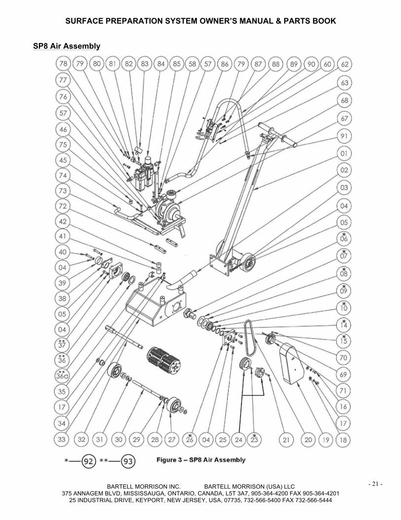
- 21 -
USP8 Air Assembly
SURFACE PREPARATION SYSTEM OWNER’S MANUAL & PARTS BOOK
BARTELL MORRISON INC. BARTELL MORRISON (USA) LLC 375 ANNAGEM BLVD, MISSISSAUGA, ONTARIO, CANADA, L5T 3A7, 905-364-4200 FAX 905-364-4201
25 INDUSTRIAL DRIVE, KEYPORT, NEW JERSEY, USA, 07735, 732-566-5400 FAX 732-566-5444
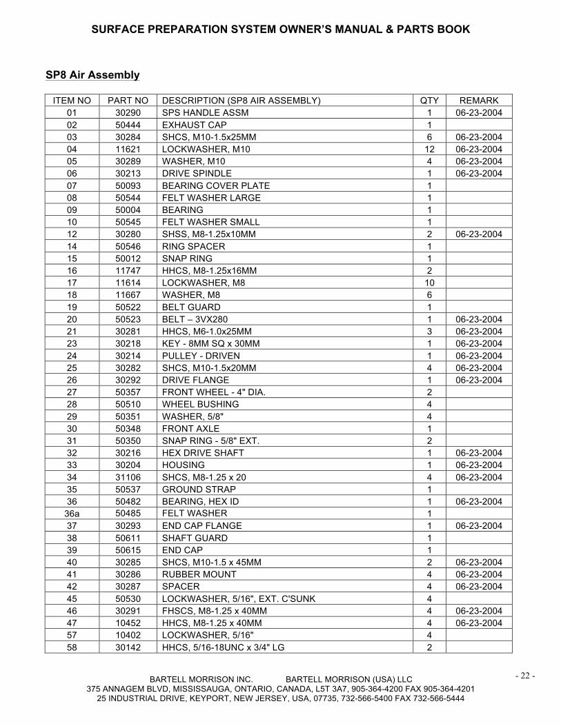
- 22 -
SP8 Air Assembly
ITEM NO PART NO DESCRIPTION (SP8 AIR ASSEMBLY) QTY REMARK 01 30290 SPS HANDLE ASSM 1 06-23-2004 02 50444 EXHAUST CAP 1 03 30284 SHCS, M10-1.5x25MM 6 06-23-2004 04 11621 LOCKWASHER, M10 12 06-23-2004 05 30289 WASHER, M10 4 06-23-2004 06 30213 DRIVE SPINDLE 1 06-23-2004 07 50093 BEARING COVER PLATE 1 08 50544 FELT WASHER LARGE 1 09 50004 BEARING 1 10 50545 FELT WASHER SMALL 1 12 30280 SHSS, M8-1.25x10MM 2 06-23-2004 14 50546 RING SPACER 1 15 50012 SNAP RING 1 16 11747 HHCS, M8-1.25x16MM 2 17 11614 LOCKWASHER, M8 10 18 11667 WASHER, M8 6 19 50522 BELT GUARD 1 20 50523 BELT – 3VX280 1 06-23-2004 21 30281 HHCS, M6-1.0x25MM 3 06-23-2004 23 30218 KEY - 8MM SQ x 30MM 1 06-23-2004 24 30214 PULLEY - DRIVEN 1 06-23-2004 25 30282 SHCS, M10-1.5x20MM 4 06-23-2004 26 30292 DRIVE FLANGE 1 06-23-2004 27 50357 FRONT WHEEL - 4" DIA. 2 28 50510 WHEEL BUSHING 4 29 50351 WASHER, 5/8" 4 30 50348 FRONT AXLE 1 31 50350 SNAP RING - 5/8" EXT. 2 32 30216 HEX DRIVE SHAFT 1 06-23-2004 33 30204 HOUSING 1 06-23-2004 34 31106 SHCS, M8-1.25 x 20 4 06-23-2004 35 50537 GROUND STRAP 1 36 50482 BEARING, HEX ID 1 06-23-2004
36a 50485 FELT WASHER 1 37 30293 END CAP FLANGE 1 06-23-2004 38 50611 SHAFT GUARD 1 39 50615 END CAP 1 40 30285 SHCS, M10-1.5 x 45MM 2 06-23-2004 41 30286 RUBBER MOUNT 4 06-23-2004 42 30287 SPACER 4 06-23-2004 45 50530 LOCKWASHER, 5/16", EXT. C'SUNK 4 46 30291 FHSCS, M8-1.25 x 40MM 4 06-23-2004 47 10452 HHCS, M8-1.25 x 40MM 4 06-23-2004 57 10402 LOCKWASHER, 5/16" 4 58 30142 HHCS, 5/16-18UNC x 3/4" LG 2
SURFACE PREPARATION SYSTEM OWNER’S MANUAL & PARTS BOOK
BARTELL MORRISON INC. BARTELL MORRISON (USA) LLC 375 ANNAGEM BLVD, MISSISSAUGA, ONTARIO, CANADA, L5T 3A7, 905-364-4200 FAX 905-364-4201
25 INDUSTRIAL DRIVE, KEYPORT, NEW JERSEY, USA, 07735, 732-566-5400 FAX 732-566-5444
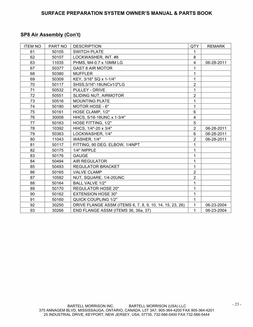
- 23 -
SP8 Air Assembly (Con’t)
ITEM NO PART NO DESCRIPTION QTY REMARK 61 50105 SWITCH PLATE 1 62 50107 LOCKWASHER, INT. #8 8 63 11035 PHMS, M4-0.7 x 10MM LG 4 06-28-2011 67 50377 GAST 8 AIR MOTOR 1 68 50380 MUFFLER 1 69 50309 KEY, 3/16" SQ x 1-1/4" 1 70 50117 SHSS,5/16"-18UNCx1/2"LG 2 71 50532 PULLEY - DRIVE 1 72 50551 SLIDING NUT, AIRMOTOR 2 73 50516 MOUNTING PLATE 1 74 50180 MOTOR HOSE - 6" 1 75 50161 HOSE CLAMP, 1/2" 6 76 30008 HHCS, 5/16-18UNC x 1-3/4" 4 77 50163 HOSE FITTING, 1/2" 5 78 10392 HHCS, 1/4"-20 x 3/4" 2 06-28-2011 79 50363 LOCKWASHER, 1/4" 6 06-28-2011 80 11043 WASHER, 1/4" 2 06-28-2011 81 50117 FITTING, 90 DEG. ELBOW, 1/4NPT 1 82 50175 1/4" NIPPLE 1 83 50176 GAUGE 1 84 50494 AIR REGULATOR 1 85 50493 REGULATOR BRACKET 1 86 50165 VALVE CLAMP 2 87 10582 NUT, SQUARE, 1/4-20UNC 2 88 50164 BALL VALVE 1/2" 1 89 50170 REGULATOR HOSE 20" 1 90 50162 EXTENSION HOSE 30" 1 91 50160 QUICK COUPLING 1/2" 1 92 30250 DRIVE FLANGE ASSM (ITEMS 6, 7, 8, 9, 10, 14, 15, 23, 26) 1 06-23-2004 93 30266 END FLANGE ASSM (ITEMS 36, 36a, 37) 1 06-23-2004
U
SURFACE PREPARATION SYSTEM OWNER’S MANUAL & PARTS BOOK
BARTELL MORRISON INC. BARTELL MORRISON (USA) LLC 375 ANNAGEM BLVD, MISSISSAUGA, ONTARIO, CANADA, L5T 3A7, 905-364-4200 FAX 905-364-4201
25 INDUSTRIAL DRIVE, KEYPORT, NEW JERSEY, USA, 07735, 732-566-5400 FAX 732-566-5444
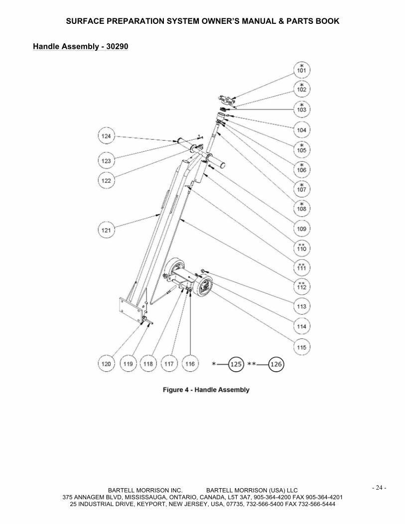
- 24 -
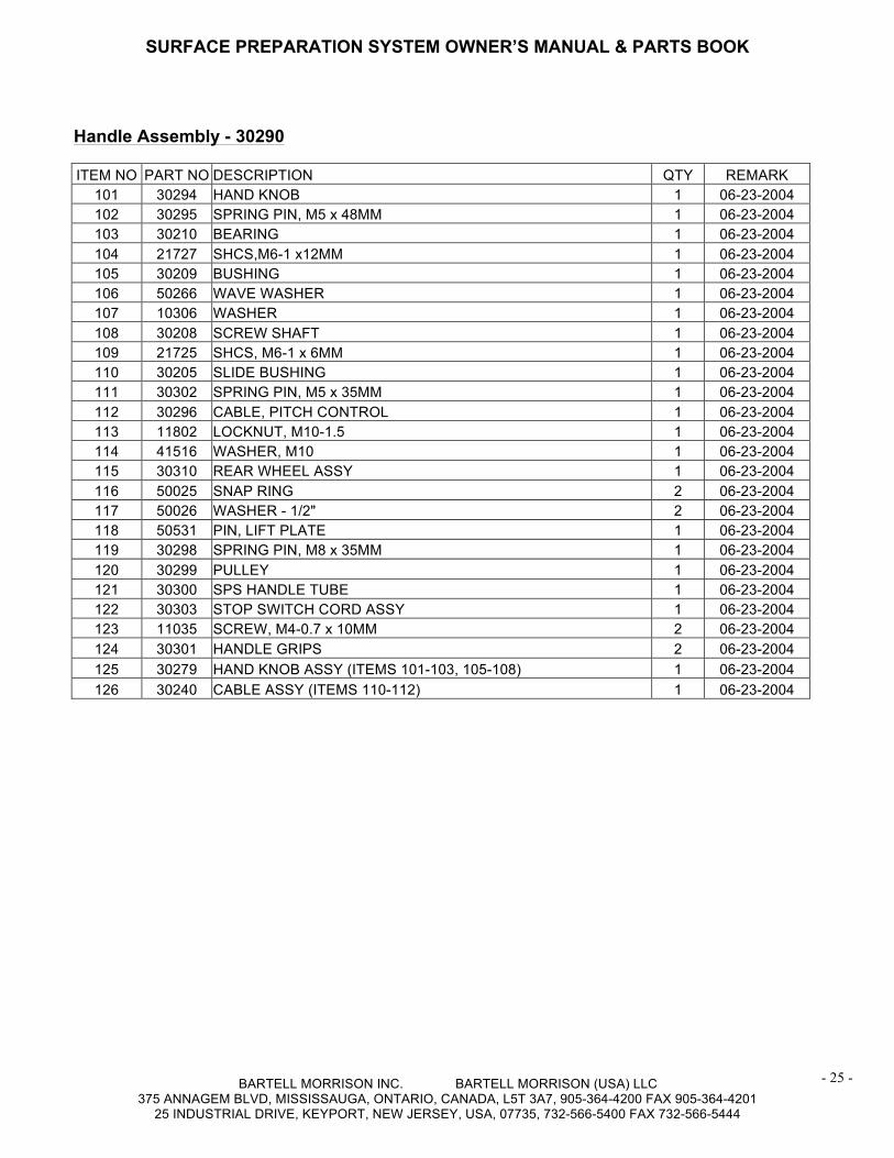
Handle Assembly - 30290
SURFACE PREPARATION SYSTEM OWNER’S MANUAL & PARTS BOOK
BARTELL MORRISON INC. BARTELL MORRISON (USA) LLC 375 ANNAGEM BLVD, MISSISSAUGA, ONTARIO, CANADA, L5T 3A7, 905-364-4200 FAX 905-364-4201
25 INDUSTRIAL DRIVE, KEYPORT, NEW JERSEY, USA, 07735, 732-566-5400 FAX 732-566-5444
- 25 -
UHandle Assembly - 30290 ITEM NO PART NO DESCRIPTION QTY REMARK
101 30294 HAND KNOB 1 06-23-2004 102 30295 SPRING PIN, M5 x 48MM 1 06-23-2004 103 30210 BEARING 1 06-23-2004 104 21727 SHCS,M6-1 x12MM 1 06-23-2004 105 30209 BUSHING 1 06-23-2004 106 50266 WAVE WASHER 1 06-23-2004 107 10306 WASHER 1 06-23-2004 108 30208 SCREW SHAFT 1 06-23-2004 109 21725 SHCS, M6-1 x 6MM 1 06-23-2004 110 30205 SLIDE BUSHING 1 06-23-2004 111 30302 SPRING PIN, M5 x 35MM 1 06-23-2004 112 30296 CABLE, PITCH CONTROL 1 06-23-2004 113 11802 LOCKNUT, M10-1.5 1 06-23-2004 114 41516 WASHER, M10 1 06-23-2004 115 30310 REAR WHEEL ASSY 1 06-23-2004 116 50025 SNAP RING 2 06-23-2004 117 50026 WASHER - 1/2" 2 06-23-2004 118 50531 PIN, LIFT PLATE 1 06-23-2004 119 30298 SPRING PIN, M8 x 35MM 1 06-23-2004 120 30299 PULLEY 1 06-23-2004 121 30300 SPS HANDLE TUBE 1 06-23-2004 122 30303 STOP SWITCH CORD ASSY 1 06-23-2004 123 11035 SCREW, M4-0.7 x 10MM 2 06-23-2004 124 30301 HANDLE GRIPS 2 06-23-2004 125 30279 HAND KNOB ASSY (ITEMS 101-103, 105-108) 1 06-23-2004 126 30240 CABLE ASSY (ITEMS 110-112) 1 06-23-2004
SURFACE PREPARATION SYSTEM OWNER’S MANUAL & PARTS BOOK
BARTELL MORRISON INC. BARTELL MORRISON (USA) LLC 375 ANNAGEM BLVD, MISSISSAUGA, ONTARIO, CANADA, L5T 3A7, 905-364-4200 FAX 905-364-4201
25 INDUSTRIAL DRIVE, KEYPORT, NEW JERSEY, USA, 07735, 732-566-5400 FAX 732-566-5444
- 26 -
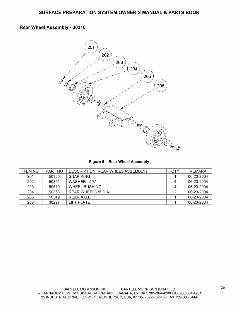
URear Wheel Assembly - 30310
Figure 5 – Rear Wheel Assembly
ITEM NO PART NO DESCRIPTION (REAR WHEEL ASSEMBLY) QTY REMARK 201 50350 SNAP RING 1 06-23-2004 202 50351 WASHER - 5/8" 4 06-23-2004 203 50510 WHEEL BUSHING 4 06-23-2004 204 50356 REAR WHEEL - 5" DIA. 2 06-23-2004 205 50349 REAR AXLE 1 06-23-2004 206 30297 LIFT PLATE 1 06-23-2004
SURFACE PREPARATION SYSTEM OWNER’S MANUAL & PARTS BOOK
BARTELL MORRISON INC. BARTELL MORRISON (USA) LLC 375 ANNAGEM BLVD, MISSISSAUGA, ONTARIO, CANADA, L5T 3A7, 905-364-4200 FAX 905-364-4201
25 INDUSTRIAL DRIVE, KEYPORT, NEW JERSEY, USA, 07735, 732-566-5400 FAX 732-566-5444
- 27 -
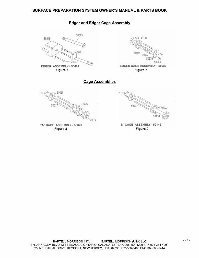
Edger and Edger Cage Assembly
Figure 6 Figure 7
Cage Assemblies
Figure 8 Figure 9
SURFACE PREPARATION SYSTEM OWNER’S MANUAL & PARTS BOOK
BARTELL MORRISON INC. BARTELL MORRISON (USA) LLC 375 ANNAGEM BLVD, MISSISSAUGA, ONTARIO, CANADA, L5T 3A7, 905-364-4200 FAX 905-364-4201
25 INDUSTRIAL DRIVE, KEYPORT, NEW JERSEY, USA, 07735, 732-566-5400 FAX 732-566-5444
- 28 -
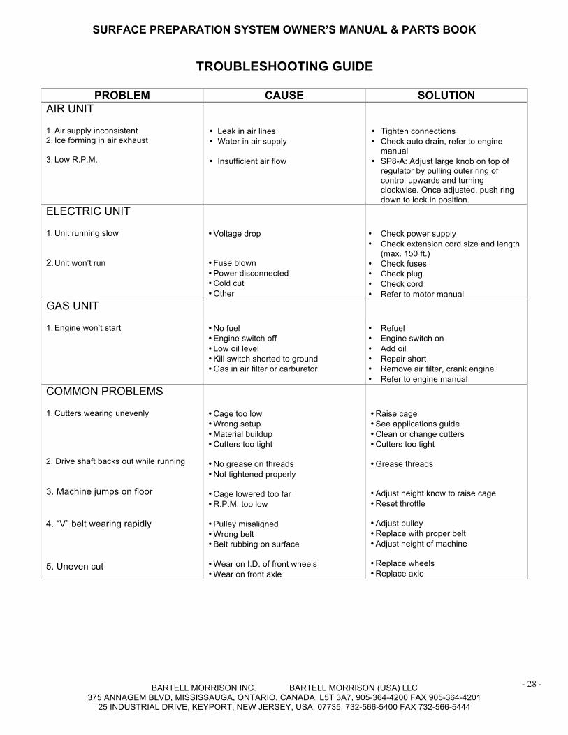
UTROUBLESHOOTING GUIDE
PROBLEM CAUSE SOLUTION AIR UNIT
1. Air supply inconsistent 2. Ice forming in air exhaust 3. Low R.P.M.
• Leak in air lines • Water in air supply • Insufficient air flow
• Tighten connections • Check auto drain, refer to engine
manual • SP8-A: Adjust large knob on top of
regulator by pulling outer ring of control upwards and turning clockwise. Once adjusted, push ring down to lock in position.
ELECTRIC UNIT
1. Unit running slow 2. Unit won’t run
• Voltage drop • Fuse blown • Power disconnected • Cold cut • Other
• Check power supply • Check extension cord size and length
(max. 150 ft.) • Check fuses • Check plug • Check cord • Refer to motor manual
GAS UNIT
1. Engine won’t start
• No fuel • Engine switch off • Low oil level • Kill switch shorted to ground • Gas in air filter or carburetor
• Refuel • Engine switch on • Add oil • Repair short • Remove air filter, crank engine • Refer to engine manual
COMMON PROBLEMS
1. Cutters wearing unevenly 2. Drive shaft backs out while running 3. Machine jumps on floor 4. “V” belt wearing rapidly 5. Uneven cut
• Cage too low • Wrong setup • Material buildup • Cutters too tight • No grease on threads • Not tightened properly • Cage lowered too far • R.P.M. too low • Pulley misaligned • Wrong belt • Belt rubbing on surface • Wear on I.D. of front wheels • Wear on front axle
• Raise cage • See applications guide • Clean or change cutters • Cutters too tight • Grease threads • Adjust height know to raise cage • Reset throttle • Adjust pulley • Replace with proper belt • Adjust height of machine • Replace wheels • Replace axle
SURFACE PREPARATION SYSTEM OWNER’S MANUAL & PARTS BOOK
BARTELL MORRISON INC. BARTELL MORRISON (USA) LLC 375 ANNAGEM BLVD, MISSISSAUGA, ONTARIO, CANADA, L5T 3A7, 905-364-4200 FAX 905-364-4201
25 INDUSTRIAL DRIVE, KEYPORT, NEW JERSEY, USA, 07735, 732-566-5400 FAX 732-566-5444
- 29 -
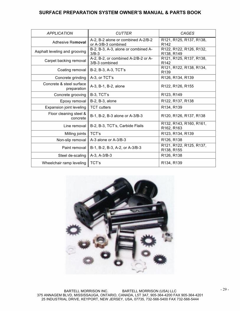
APPLICATION CUTTER CAGES
Adhesive Removal A-2, B-2 alone or combined A-2/B-2 or A-3/B-3 combined
R121, R125, R137, R138, R142
Asphalt leveling and grooving B-2, B-3, A-3, alone or combined A-3/B-3
R122, R122, R126, R132, R138, R149
Carpet backing removal A-2, B-2, or combined A-2/B-2 or A-3/B-3 combined
R121, R125, R137, R138, R142
Coating removal B-2, B-3, A-3, TCT’s R121, R122, R138, R134, R139
Concrete grinding A-3, or TCT’s R126, R134, R139 Concrete & steel surface
preparation A-3, B-1, B-2, alone R122, R126, R155
Concrete grooving B-3, TCT’s R123, R149 Epoxy removal B-2, B-3, alone R122, R137, R138
Expansion joint leveling TCT cutters R134, R139 Floor cleaning steel &
concrete B-1, B-2, B-3 alone or A-3/B-3 R120, R126, R137, R138
Line removal B-2, B-3, TCT’s, Carbide Flails R132, R143, R160, R161, R162, R163
Milling joints TCT’s R123, R134, R139 Non-slip removal A-3 alone or A-3/B-3 R126, R138
Paint removal B-1, B-2, B-3, A-2, or A-3/B-3 R121, R122, R125, R137, R138, R155
Steel de-scaling A-3, A-3/B-3 R126, R138
Wheelchair ramp leveling TCT’s R134, R139
SURFACE PREPARATION SYSTEM OWNER’S MANUAL & PARTS BOOK
BARTELL MORRISON INC. BARTELL MORRISON (USA) LLC 375 ANNAGEM BLVD, MISSISSAUGA, ONTARIO, CANADA, L5T 3A7, 905-364-4200 FAX 905-364-4201
25 INDUSTRIAL DRIVE, KEYPORT, NEW JERSEY, USA, 07735, 732-566-5400 FAX 732-566-5444
- 30 -
USPECIFICATIONS
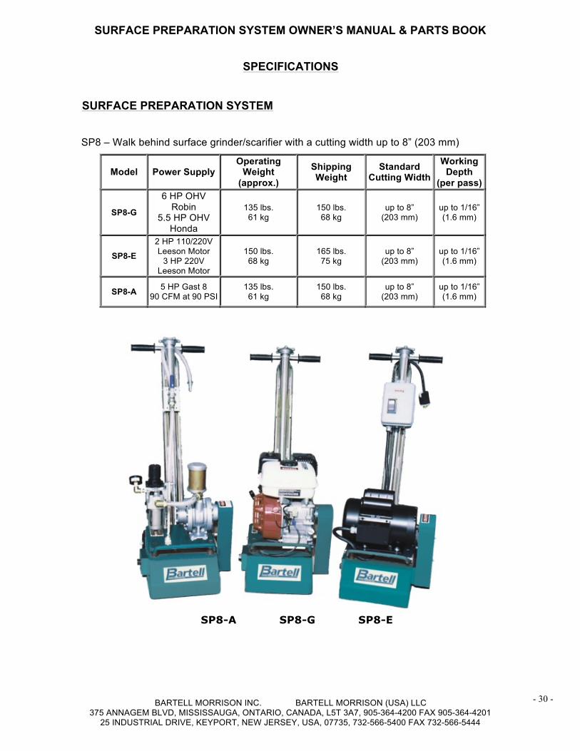
USURFACE PREPARATION SYSTEM SP8 – Walk behind surface grinder/scarifier with a cutting width up to 8” (203 mm)
SP8-A SP8-G SP8-E
Model Power Supply Operating
Weight (approx.)
Shipping Weight
Standard Cutting Width
Working Depth
(per pass)
SP8-G
6 HP OHV Robin
5.5 HP OHV Honda
135 lbs. 61 kg
150 lbs. 68 kg
up to 8” (203 mm)
up to 1/16” (1.6 mm)
SP8-E 2 HP 110/220V Leeson Motor
3 HP 220V Leeson Motor
150 lbs. 68 kg
165 lbs. 75 kg
up to 8” (203 mm)
up to 1/16” (1.6 mm)
SP8-A 5 HP Gast 8 90 CFM at 90 PSI
135 lbs. 61 kg
150 lbs. 68 kg
up to 8” (203 mm)
up to 1/16” (1.6 mm)
SURFACE PREPARATION SYSTEM OWNER’S MANUAL & PARTS BOOK
BARTELL MORRISON INC. BARTELL MORRISON (USA) LLC 375 ANNAGEM BLVD, MISSISSAUGA, ONTARIO, CANADA, L5T 3A7, 905-364-4200 FAX 905-364-4201
25 INDUSTRIAL DRIVE, KEYPORT, NEW JERSEY, USA, 07735, 732-566-5400 FAX 732-566-5444
- 31 -
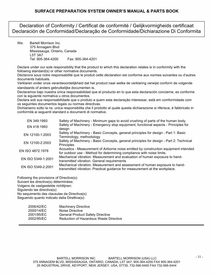
We: Bartell Morrison Inc. 375 Annagem Blvd Mississauga, Ontario, Canada L5T 3A7 Tel: 905-364-4200 Fax: 905-364-4201 Declare under our sole responsibility that the product to which this declaration relates is in conformity with the following standard(s) or other normative documents. Déclarons sous notre responsabilité que le produit cette déclaration est conforme aux normes suivantes ou d’autres documents habituels. Verklaren onder onze verantwoordelijkheid dat het product naar welke de verklaring verwijst conform de volgende standaards of anders gebruikelijke documenten is. Declaramos bajo nuestra única responsabilidad que el producto en lo que esta declaración concierne, es conforme con la siguiente normativa u otros documentos. Declara sob sua responsabilidade que o produto a quem esta declaração interessar, está em comformidade com os seguintes documentos legais ou normas directivas. Dichiariamo sotto la ns. unica responsibilita che il prodotto al quale questa dichiarazione si riferisce, è fabbricato in conformità ai seguenti standard e documenti di normative.
EN 349:1993 Safety of Machinery - Minimum gaps to avoid crushing of parts of the human body.
EN 418:1993 Safety of Machinery - Emergency stop equipment, functional aspects - Principles for design
EN 12100-1:2003 Safety of Machinery - Basic Concepts, general principles for design - Part 1: Basic Terminology, methodology
EN 12100-2:2003 Safety of Machinery - Basic Concepts, general principles for design - Part 2: Technical Principles
EN ISO 4872:1978 Acoustics - Measurement of Airborne noise emitted by construction equipment intended for outdoor use - Method for determining compliance with noise limits.
EN ISO 5349-1:2001 Mechanical vibration. Measurement and evaluation of human exposure to hand-transmitted vibration. General requirements
EN ISO 5349-2:2001 Mechanical vibration. Measurement and assessment of human exposure to hand-transmitted vibration. Practical guidance for measurement at the workplace.
Following the provisions of Directive(s): Suivant les directive(s) déterminées: Volgens de vastgestelde richtlijnen: Siguiendo las directiva(s): No sequimento das clausulas da Directiva(s): Seguendo quanto indicato dalla Direttiva(s):
2006/42/EC Machinery Directive 2000/14/EC Noise Directive 2001/95/EC General Product Safety Directive 2002/95/EC Reduction of Hazardous Waste Directive
Declaration of Conformity / Certificat de conformité / Gelijkvormigheids certificaat Declaración de Conformidad/Declaração de Conformidade/Dichiarazione Di Conformita
SURFACE PREPARATION SYSTEM OWNER’S MANUAL & PARTS BOOK
BARTELL MORRISON INC. BARTELL MORRISON (USA) LLC 375 ANNAGEM BLVD, MISSISSAUGA, ONTARIO, CANADA, L5T 3A7, 905-364-4200 FAX 905-364-4201
25 INDUSTRIAL DRIVE, KEYPORT, NEW JERSEY, USA, 07735, 732-566-5400 FAX 732-566-5444
- 32 -
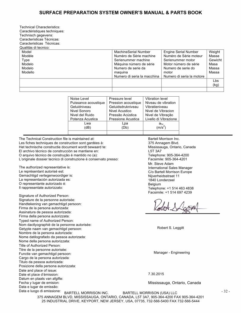
Technical Characteristics: Caractéristiques techniques: Technisch gegevens: Características Técnicas: Caracteristicas Técnicas: Qualitàs di tecnico:
Model Modéle Type Modelo Modelo Modello
MachineSerial Number Numéro de Série machine Serienummer machine Máquina número de série Numero de serie da maquina Numero di seria la macchina
Engine Serial Number Numéro de Série moteur Serienummer motor Motor número de série Numero de serie do motor Numero di seria la motore
Weight Masse Gewicht Masa Massa Massa
Lbs (kg)
Noise Level Puissance acoustique Geluidniveau Nivel Sonoro Nivel del Ruido Potenza Acustica
Pressure level Pression acoustique Geluidsdrukniveau Nivel Acustico Pressão Acústica Pressione Acustica
Vibration level Niveau de vibration Vibratieniveau Nivel de Vibracion Nivel de Vibração Livello di Vibrazione
Lwa (dB)
Lpa (Db)
ahv (m/s2)
The Technical Construction file is maintained at: Les fiches techniques de construction sont gardées à: Het technische constructie document wordt bewaard te: El archivo técnico de construcción se mantiene en: O arquivo técnico de construção é mantido no (a): L’originale dossier tecnico di construzione è conservato presso:
Bartell Morrison Inc. 375 Annagem Blvd. Mississauga, Ontario, Canada L5T 3A7 Telephone: 905-364-4200 Facsimile: 905-364-4201
The authorized representative is: Le représentant autorisé est: Gemachtigd vertegenwoordiger is: La representación autorizada es: O representante autorizado é: Il rappresentate autorizzato:
Mr. Steve Adam International Sales Manager C/o Bartell Morrison Europe Nijverheidsstraat 11 1840 Londerzeel Belgium Telephone: +1 514 463 4838 Facsimile: +1 514 697 4239
Signature of Authorized Person: Signature de la personne autorisée: Handtekening van gemachtigd persoon: Firma de la persona autorizada: Assinatura de pessoa autorizada: Firma della persona autorizzata: Typed name of Authorized Person: Nom dactlyographié de la personne autorisée: Getypte naam van gemachtigd persoon: Nombre de la persona autorizada: Nome datilografado da pessoa autorizada: Nome della persona autorizzata:
Robert S. Leggitt
Title of Authorized Person: Titre de la personne autorisée: Functie van gemachtigd persoon: Cargo de la persona autorizada: Titulo da pessoa autorizada: Posizione della persona autorizzata:
Manager - Engineering
Date and place of issue: Date et place d’émission: Datum en plaats van afgifte: Fecha y lugar de emision: Data e lugar de emissão: Data e luogo di emissione:
7.30.2015 Mississauga, Ontario, Canada

SURFACE PREPARATION SYSTEM OWNER’S MANUAL & PARTS BOOK
BARTELL MORRISON INC. BARTELL MORRISON (USA) LLC 375 ANNAGEM BLVD, MISSISSAUGA, ONTARIO, CANADA, L5T 3A7, 905-364-4200 FAX 905-364-4201
25 INDUSTRIAL DRIVE, KEYPORT, NEW JERSEY, USA, 07735, 732-566-5400 FAX 732-566-5444
- 33 -
NOTES

SURFACE PREPARATION SYSTEM OWNER’S MANUAL & PARTS BOOK
BARTELL MORRISON INC. BARTELL MORRISON (USA) LLC 375 ANNAGEM BLVD, MISSISSAUGA, ONTARIO, CANADA, L5T 3A7, 905-364-4200 FAX 905-364-4201
25 INDUSTRIAL DRIVE, KEYPORT, NEW JERSEY, USA, 07735, 732-566-5400 FAX 732-566-5444
- 34 -
NOTES