Embed Size (px)
Citation preview

8/7/2019 09 Sedan Steering Wheel Trim
http://slidepdf.com/reader/full/09-sedan-steering-wheel-trim 1/7
Publications No.
Issue Date
INSTALLATIONINSTRUCTIONS
Accessory Application
© 2008 American Honda Motor Co., Inc. – All Rights Reserved. AII 40008 (0807) 1 of 708Z13-TA0-1000-91
AII 40008
STEERING WHEEL TRIM 2009 ACCORD
4-DOORJULY 2008
PARTS LIST
Steering Wheel Trim (Without Navigation)P/N 08Z13-TA0-100
Right steering wheel trim
Left steering wheel trim
2 Torx bolts
Steering Wheel Trim (With Navigation)P/N 08Z13-TA0-100A
Right steering wheel trim
Left steering wheel trim
2 Torx bolts
TOOLS REQUIRED
Phillips screwdriver
Flat-tip screwdriver
14 mm T-handle wrench
Torque wrench
14 mm Socket wrench
Steering wheel puller
T30 Torx bit
INSTALLATION
NOTE:
• Observe all safety notes and precautions described inthe service manual in addition to these described in this
installation instruction.
• After installing the steering wheel, you must align the
steering wheel spoke angle to the straight-aheadposition by adjusting the front toe.
1. Make sure you have the anti-theft codes for the radio
and navigation system (if equipped), then write downthe radio presets.
2. Disconnect the negative cable from the battery, and
wait for at least 3 minutes before you start to installthe steering wheel trim.
Customer Information: The information in this
installation instruction is intended for use only by skilledtechnicians who have the proper tools, equipment, and
training to correctly and safely add equipment to yourvehicle. These procedures should not be attempted by“do-it-yourselfers.”

8/7/2019 09 Sedan Steering Wheel Trim
http://slidepdf.com/reader/full/09-sedan-steering-wheel-trim 2/7
2 of 7 AII 40008 (0807) © 2008 American Honda Motor Co., Inc. – All Rights Reserved.
3. From under the driver’s side airbag, pry up on the
four retaining tabs, and remove the access panel.
4. Remove the horn ground terminal and the airbagconnectors from the holder on the cord guide.
Unplug the horn ground terminals and the airbagconnectors.
5. While holding the pin insulator, pull out on the coverinsulator. Do not pull on the socket insulator andharness wires.
6D1201AE
HORN GROUNDTERMINALS
HOLDER ON THECORD GUIDE
ACCESSPANEL
4 RETAININGTABS
AIRBAGCONNECTORS
COVERINSULATOR
SOCKETINSULATOR
Do not pull onthe harnesswires.
COVERINSULATOR
PININSULATOR PIN
INSULATOR
SOCKETINSULATOR
Do not pull on theharness wires.
AIRBAG
AIRBAG CONNECTOR
HORN GROUNDTERMINAL
6. Remove and discard the two Torx bolts that secure
the airbag, and remove the airbag. Carefully set theairbag in a secure location with the pad facing up. Do
not drop or bump the airbag against anything.
750902AE
AIRBAG
TORX BOLT(Discard.)
TORX BOLT(Discard.)
8/7/2019 09 Sedan Steering Wheel Trim
http://slidepdf.com/reader/full/09-sedan-steering-wheel-trim 3/7
© 2008 American Honda Motor Co., Inc. – All Rights Reserved. AII 40008 (0807) 3 of 7
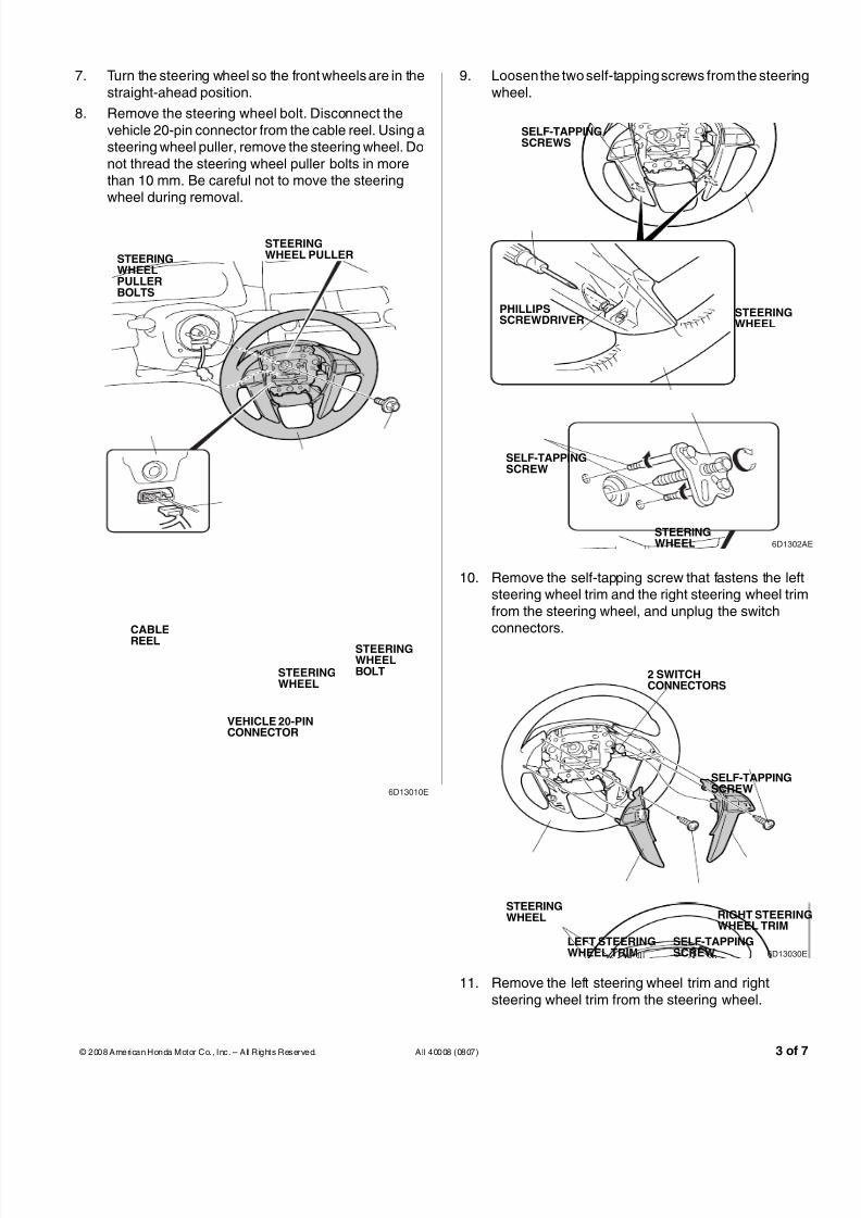
7. Turn the steering wheel so the front wheels are in the
straight-ahead position.
8. Remove the steering wheel bolt. Disconnect the
vehicle 20-pin connector from the cable reel. Using asteering wheel puller, remove the steering wheel. Do
not thread the steering wheel puller bolts in morethan 10 mm. Be careful not to move the steeringwheel during removal.
6D13010E
STEERINGWHEELPULLERBOLTS
STEERINGWHEEL PULLER
STEERINGWHEELBOLTSTEERING
WHEEL
CABLE
REEL
VEHICLE 20-PINCONNECTOR
9. Loosen the two self-tapping screws from the steering
wheel.
10. Remove the self-tapping screw that fastens the leftsteering wheel trim and the right steering wheel trim
from the steering wheel, and unplug the switchconnectors.
11. Remove the left steering wheel trim and right
steering wheel trim from the steering wheel.
6D1302A
SELF-TAPPINGSCREWS
STEERINGWHEEL
STEERINGWHEEL
SELF-TAPPINGSCREW
PHILLIPSSCREWDRIVER
6D13030E
STEERINGWHEEL
2 SWITCHCONNECTORS
SELF-TAPPINGSCREW
LEFT STEERINGWHEEL TRIM
RIGHT STEERINGWHEEL TRIM
SELF-TAPPINGSCREW

8/7/2019 09 Sedan Steering Wheel Trim
http://slidepdf.com/reader/full/09-sedan-steering-wheel-trim 4/7
4 of 7 AII 40008 (0807) © 2008 American Honda Motor Co., Inc. – All Rights Reserved.
For vehicles without a NAVI switch continue with step 12.
For vehicles with a NAVI switch, go to step 14.
Without NAVI Switch
12. Remove the four screws that fasten the two switchesfrom the left steering wheel trim and right steering
wheel trim, release the retaining tabs, and removethe two switches.
13. Install the two switches to the new left steering wheeltrim and new right steering wheel trim with the four
screws (reuse). Make sure the retaining tabs are
engaged. Go to step 16.
6D13040E
4 SCREWS
2 SWITCHES
LEFT STEERINGWHEEL TRIM
RIGHT STEERINGWHEEL TRIM
RETAININGTAB
NAVISWITCH
RETAININGTAB
RETAININGTAB
6D13040E
4 SCREWS(Reuse.)
2 SWITCHES(Reuse.)
NEW LEFTSTEERINGWHEEL TRIM
NEW RIGHTSTEERINGWHEEL TRIM
With NAVI Switch
14. Remove the five screws that fasten the two switchesand NAVI switch from the left steering wheel trim and
right steering wheel trim, release the retaining tab,and remove the two switches and NAVI switch.
15. Install the two switches and NAVI switch to the new
left steering wheel trim and new right steering wheeltrim with the five screws (reuse). Make sure the
retaining tabs are engaged.
6D13050E
2 SWITCHES
5 SCREWS
NAVI
SWITCH
NAVI SWITCH
SWITCH
SCREW
LEFT STEERINGWHEEL TRIM
RIGHT STEERINGWHEEL TRIM
LEFTSTEERINGWHEELTRIM
RETAININGTAB
RETAININGTAB
RETAININGTABS
6D13050E
2 SWITCHES(Reuse.)
5 SCREWS(Reuse.)
NAVISWITCH(Reuse.)
NAVI SWITCH
SWITCH
SCREW
NEW LEFTSTEERINGWHEEL TRIM
NEW RIGHTSTEERINGWHEEL TRIM
LEFTSTEERINGWHEELTRIM

8/7/2019 09 Sedan Steering Wheel Trim
http://slidepdf.com/reader/full/09-sedan-steering-wheel-trim 5/7
© 2008 American Honda Motor Co., Inc. – All Rights Reserved. AII 40008 (0807) 5 of 7
16. Connect each switch connector and install each new
steering wheel trim to the steering wheel with the twoscrews you removed.
17. Reinstall the two self-tapping screws to the steering
wheel.
6D13030E
2 SWITCHCONNECTORS
SWITCH
SCREW(reused)
SWITCHSTEERINGWHEEL
NEW LEFT
STEERINGWHEEL TRIM
NEW RIGHTSTEERINGWHEEL TRIM
SCREW
(reused)
SWITCHCONNECTORS
6D1302AE
STEERINGWHEEL
SELF-TAPPINGSCREWS(reused)
STEERINGWHEEL
SELF-TAPPINGSCREW
PHILLIPSSCREWDRIVER
If the cable reel was moved, continue with step 18; if it was
not moved, go to step 19.
18. Align the cable reel:
• Rotate the cable reel clockwise all the way untiit stops.
• Turn the cable reel counterclockwise about threecomplete turns until the “TOP” arrow on the
cable reel points up.19. Install the steering wheel on the steering column
shaft in the straight-ahead position:
• Route the wire harness through the opening in
the steering wheel.
• Align the two tabs of the cancelling sleeve with
the two cutouts in the steering wheel as shown
• Check that the wire harness are not pinched.
20. Install the steering wheel bolt. Torque the steeringwheel bolt to 49 N·m (36 lb-ft).
21. Reconnect the 20-pin connectors.
6D13060E
STEERINGWHEEL
STEERING WHEELBOLT (reused)Torque to 49 N·m(36 lb-ft)
CABLEREEL
VEHICLE 20-PINCONNECTOR
STEERINGCOLUMNSHAFT
CUTOUTSTAB
8/7/2019 09 Sedan Steering Wheel Trim
http://slidepdf.com/reader/full/09-sedan-steering-wheel-trim 6/7
6 of 7 AII 40008 (0807) © 2008 American Honda Motor Co., Inc. – All Rights Reserved.
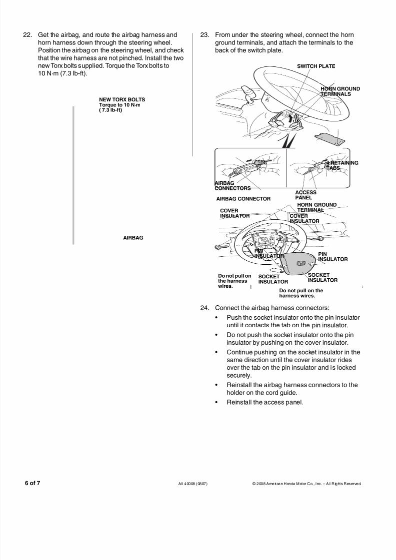
22. Get the airbag, and route the airbag harness and
horn harness down through the steering wheel.Position the airbag on the steering wheel, and check
that the wire harness are not pinched. Install the twonew Torx bolts supplied. Torque the Torx bolts to10 N·m (7.3 lb-ft).
750902AE
AIRBAG
NEW TORX BOLTSTorque to 10 N·m( 7.3 lb-ft)
23. From under the steering wheel, connect the horn
ground terminals, and attach the terminals to theback of the switch plate.
24. Connect the airbag harness connectors:
• Push the socket insulator onto the pin insulatoruntil it contacts the tab on the pin insulator.
• Do not push the socket insulator onto the pininsulator by pushing on the cover insulator.
• Continue pushing on the socket insulator in thesame direction until the cover insulator ridesover the tab on the pin insulator and is locked
securely.
• Reinstall the airbag harness connectors to the
holder on the cord guide.• Reinstall the access panel.
6D1307AE
HORN GROUNDTERMINALS
SWITCH PLATE
ACCESSPANEL
4 RETAININGTABS
AIRBAGCONNECTORS
COVERINSULATOR
SOCKETINSULATOR
Do not pull onthe harnesswires.
COVERINSULATOR
PININSULATOR PIN
INSULATOR
SOCKETINSULATOR
Do not pull on theharness wires.
AIRBAG CONNECTORHORN GROUNDTERMINAL

8/7/2019 09 Sedan Steering Wheel Trim
http://slidepdf.com/reader/full/09-sedan-steering-wheel-trim 7/7
© 2008 American Honda Motor Co., Inc. – All Rights Reserved. AII 40008 (0807) 7 of 7
25. Reconnect the negative cable to the battery.
26. Make sure the steering wheel is in the straight-aheadposition with the front wheels. If the spoke angle of
the steering wheel is not in the straight-aheadposition with the front wheels, adjust the front toe as
described in the service manual.
27. Verify that the horn works.
28. Turn the ignition key on, and verify that the SRSwarning light comes on and stays on for 6 seconds;
turn the key off to make sure the SRS indicator goesoff.
29. Enter the anti-theft code for the radio and the
navigation system (if equipped), then reset thecustomer’s radio presets.
30. Reset the clock on models without navigation.