Embed Size (px)
Citation preview

08V07/04
R Valve
Cast Steel Temperature Control Valve
Key benefits
No leak design - No external moving parts - No external dynamic seals
Easily removable elements
Environmentally friendly, reliable performance
Easy installation - operates in any mounting position
Typical applications
Refrigeration compressors
Industrial compressors
Turbines
Engines
Gear boxes
High pressure applications
+44 (0)1284 762222

+44 (0)1284 762222 08V/i
Operation
The temperature control power is created by the expansion of a wax/copper mixture which is highly sensitive to temperature changes.
Large forces are created by the warming/expansion of the mixture which in turn acts upon the sliding valve, thus regulating the flow.
The diagram opposite shows the valve actuation in diverting mode at start and cooling positions.
During operation the sliding valve constantly modulates for accurate temperature control.
The reliable rugged construction provides a unit sensitive to temperature variations, not easily disturbed by pressure changes and sudden surges, which maintains stable temperatures over a wide range of operating conditions.
Positive acting temperature control
AMOT thermostatic valves provide reliable control of fluid temperatures in cooling systems, heat recovery and many other temperature control applications.
They are also suitable for process control and industrial applications where fluids must be mixed or diverted depending upon temperature.
All AMOT internally sensed valves have positive 3-way action. This ensures that on process start up all of the flow is through the bypass line giving the fastest possible warm up time.
Operation and flow control is established by the temperature element, which constantly monitors and regulates the medium to the exact specified temperature setting.
When required the valve will positively shut off the bypass line to give full cooling.
A 3-way valve ensures constant volume flow in the system and gives no restriction during the warm up cycle, ensuring maximum performance. Where shut off is not required, bypass holes are available.

+44 (0)1284 762222 08V/ii
Body material Cast steel BS 3146 CLA 1A-ASTM A216 WCB-DIN 17245 Grade 1.0169 (GSC 25N)
Element material Standard elements are of electroless Elements without plating available nickel plated brass and bronze (refer to specification check list on page ix)
Seal materials Neoprene/VITON
Port connections Flanged or welded. Refer to part number specification check list on page ix for detail
Valve sizes 20 - 80mm (3/4” - 3”) (nominal bore)
Control temperatures 35˚C to 82˚C (95˚F to 180˚F)
Flow rate 4 to 70m3/hour Based on water (18 to 308 US gpm)
Pressure rating 10 - 45 bar (145 - 650 psi)
Recommended pressure 0.14 to 0.48 bar (2 to 7 psi) drop
Typical installation diagrams
heatremoval
heatremoval
heatload
heatload
pumppump
A
A
B
B
C
C
AMOTthermostat
AMOTthermostat
coldinlet
hotinlet
heatremoval
bypass
A A
B BC C
Specification
Connection versus size availability
Size mm (“) B C J H X Y Z T U
20 (3/4)
25 (1)
40 (1 1/2)
50 (2)
65 (2 1/2)
80 (3)
Model/size availability
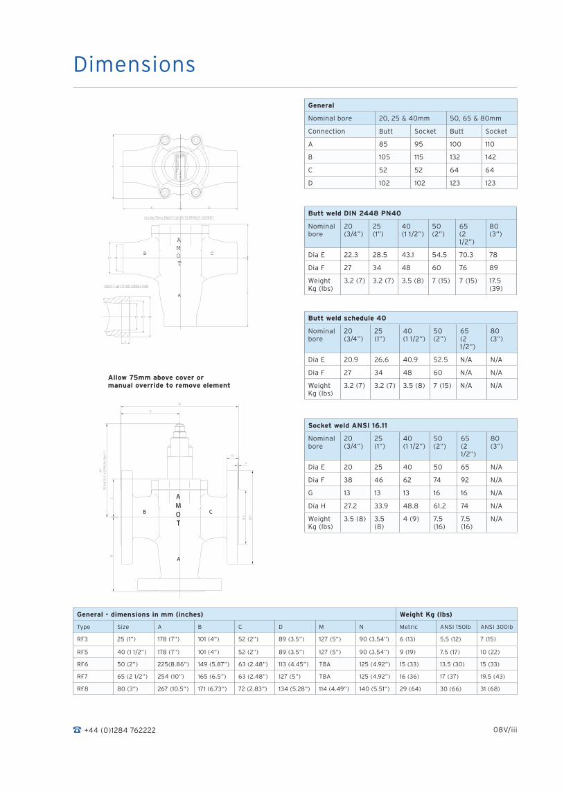
Dimensions
A
B C
AMOT CONTROLS
OMA
T
General
Nominal bore 20, 25 & 40mm 50, 65 & 80mm
Connection Butt Socket Butt Socket
A 85 95 100 110
B 105 115 132 142
C 52 52 64 64
D 102 102 123 123
Butt weld DIN 2448 PN40
Nominal bore
20 (3/4”)
25 (1”)
40 (1 1/2”)
50 (2”)
65 (2 1/2”)
80 (3”)
Dia E 22.3 28.5 43.1 54.5 70.3 78
Dia F 27 34 48 60 76 89
Weight Kg (lbs)
3.2 (7) 3.2 (7) 3.5 (8) 7 (15) 7 (15) 17.5 (39)
Butt weld schedule 40
Nominal bore
20 (3/4”)
25 (1”)
40 (1 1/2”)
50 (2”)
65 (2 1/2”)
80 (3”)
Dia E 20.9 26.6 40.9 52.5 N/A N/A
Dia F 27 34 48 60 N/A N/A
Weight Kg (lbs)
3.2 (7) 3.2 (7) 3.5 (8) 7 (15) N/A N/A
Socket weld ANSI 16.11
Nominal bore
20 (3/4”)
25 (1”)
40 (1 1/2”)
50 (2”)
65 (2 1/2”)
80 (3”)
Dia E 20 25 40 50 65 N/A
Dia F 38 46 62 74 92 N/A
G 13 13 13 16 16 N/A
Dia H 27.2 33.9 48.8 61.2 74 N/A
Weight Kg (lbs)
3.5 (8) 3.5 (8)
4 (9) 7.5 (16)
7.5 (16)
N/A
General - dimensions in mm (inches) Weight Kg (lbs)
Type Size A B C D M N Metric ANSI 150lb ANSI 300lb
RF3 25 (1”) 178 (7”) 101 (4”) 52 (2”) 89 (3.5”) 127 (5”) 90 (3.54”) 6 (13) 5.5 (12) 7 (15)
RF5 40 (1 1/2”) 178 (7”) 101 (4”) 52 (2”) 89 (3.5”) 127 (5”) 90 (3.54”) 9 (19) 7.5 (17) 10 (22)
RF6 50 (2”) 225(8.86”) 149 (5.87”) 63 (2.48”) 113 (4.45”) TBA 125 (4.92”) 15 (33) 13.5 (30) 15 (33)
RF7 65 (2 1/2”) 254 (10”) 165 (6.5”) 63 (2.48”) 127 (5”) TBA 125 (4.92”) 16 (36) 17 (37) 19.5 (43)
RF8 80 (3”) 267 (10.5”) 171 (6.73”) 72 (2.83”) 134 (5.28”) 114 (4.49”) 140 (5.51”) 29 (64) 30 (66) 31 (68)
+44 (0)1284 762222 08V/iii
�
� ����
�
Allow 75mm above cover or manual override to remove element

Flange details - ND10/ND16
Type Dia E Dia F G H Dia K Dia L N J
RF3 115 (4.53”) 68 (2.68”) 16 (0.63”) 2 (0.08”) 85 (3.35”) 14 (0.55”) 4 45°
RF5 150 (5.91”) 88 (3.46”) 18 (0.71”) 3 (0.12”) 110 (4.33”) 18 (0.71”) 4 45°
RF6 165 (6.5”) 102 (4.02”) 20 (0.79”) 3 (0.12”) 125 (4.92”) 18 (0.71”) 4 45°
RF7 185 (7.28”) 122 (4.80”) 20 (0.79”) 3 (0.12”) 145 (5.71”) 18 (0.71”) 4 45°
RF8 200 (7.87”) 138 (5.43”) 22 (0.87”) 3 (0.12”) 160 (6.3”) 18 (0.71”) 8 22.5°
Dimensions continued
+44 (0)1284 762222 08V/iv
Flange details - ANSI 150lb
Type Dia E Dia F G H Dia K Dia L N J
RF3 108 (4.25”) 66.5 (2.62”) 14.2 (0.56”) 1.52 (0.06”) 79.2 (3.12”) 15.7 (0.62”) 4 45°
RF5 127 (5”) 73.2 (2.88”) 17.5 (0.69”) 1.52 (0.06”) 98.6 (3.88”) 15.7 (0.62”) 4 45°
RF6 152.4 (6”) 92 (3.62”) 19.5 (0.77”) 1.52 (0.06”) 120.7 (4.75”) 19.5 (0.77”) 4 45°
RF7 177.8 (7”) 104.6 (4.12”) 22.4 (0.88”) 1.52 (0.06”) 139.7 (5.5”) 19.5 (0.77”) 4 45°
RF8 190.5 (7.5”) 127 (5”) 25.5 (1”) 1.52 (0.06”) 152.4 (6”) 19.05(0.75”) 4 45°
Flange details - ANSI 300lb
Type Dia E Dia F G H Dia K Dia L N J
RF3 124 (4.88”) 66.5 (2.62”) 17.5 (0.69”) 1.52 (0.06”) 88.9 (3.5”) 19.05 (0.75”)
4 45°
RF5 155.4 (6.12”) 73.2 (2.88”) 20.6 (0.81”) 1.52 (0.06”) 114.3 (4.5”) 22.4 (0.88”) 8 22.5°
RF6 165.1 (4.5”) 92 (23.62”) 22.5 (0.89”) 1.52 (0.06”) 127 (5”) 22.4 (0.88”) 8 22.5°
RF7 190.5 (7.5”) 104.6 (4.12”) 25.4 (1”) 1.52 (0.06”) 149.4 (5.88”) 22.4 (0.88”) 8 22.5°
RF8 209.6 (8.25”) 127 (5”) 28.4 (1.12”) 1.52 (0.06”) 168.1 (6.62”) 22.4 (0.88”) 8 22.5°

+44 (0)1284 762222 08V/v
Temperature settings
A wide selection of temperatures are available. Follow the equipment manufacturers’ guidelines for oil systems and for specific operating temperatures of cooling/heating systems.
In general the temperature quoted is the nominal operating temperature in diverting mode on water systems.
For long life AMOT valves should not be operated continuously at temperatures in excess of their maximum continuous rating. If this condition is anticipated then consult AMOT for suitable alternatives.
For mixing and oil circuits the temperature may be 1 to 20C higher due to flow, viscosity and other system parameters.
Leakholes
Leakholes can be drilled to allow fluid between ports B and C:
1. To allow small flows to cooler during start up which slows down warm up cycle.
2. To allow small flows to maintain some flow through cooler in order to prevent condensation or, in extreme cases, freezing. In applications where additives are not or cannot be used.
In applications where a valve is used as 2-way, with port ‘B’ blocked and when the circuit is cold and the valve closed, a leakhole is necessary to ensure small flow in order to detect a temperature change in the system.
+44 (0)1284 762222 08V/vi
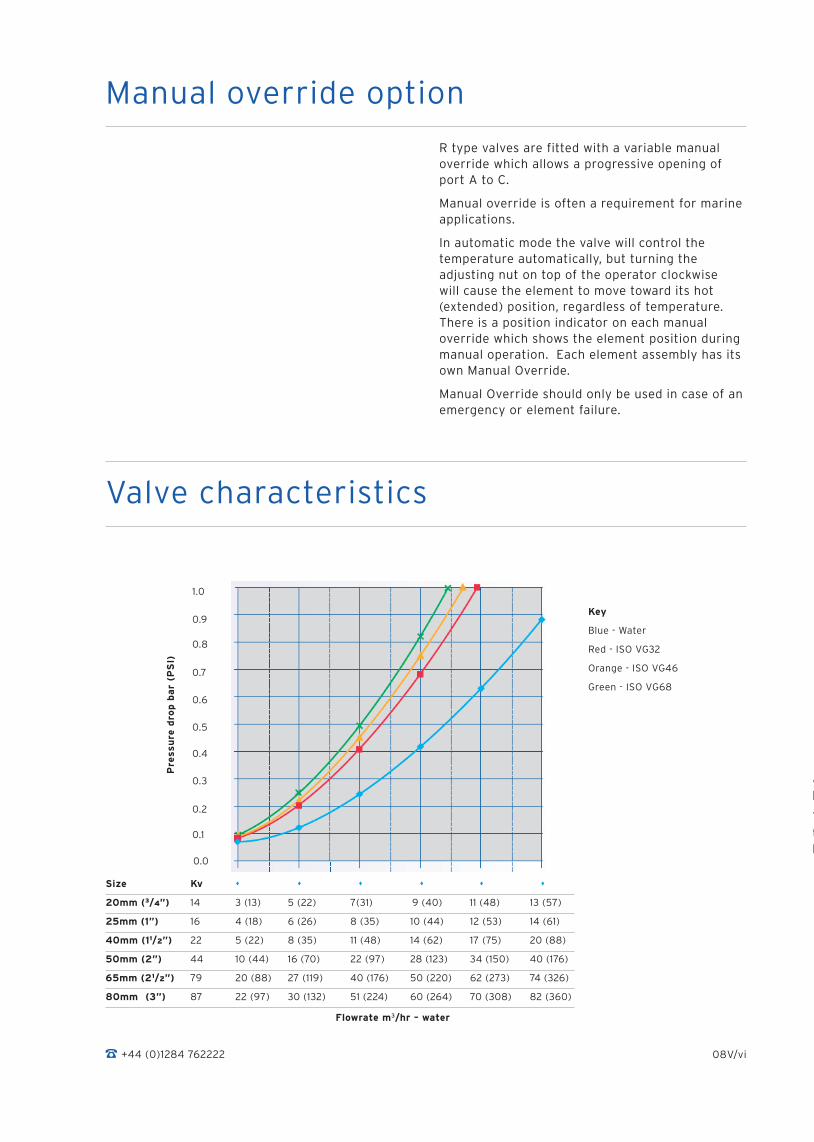
Valve characteristics
Flowrate m3/hr – water
Pre
ssu
re d
rop
ba
r (P
SI)
0.3
0.2
0.1
0.0
AMOT thermostatic valves are designed to produce minimal pressure drop.
The normal recommendation in sizing AMOT thermostatic valves is to select a pressure drop between 0.14 to 0.5 bar (2 and 7 PSI).
Manual override option
R type valves are fitted with a variable manual override which allows a progressive opening of port A to C.
Manual override is often a requirement for marine applications.
In automatic mode the valve will control the temperature automatically, but turning the adjusting nut on top of the operator clockwise will cause the element to move toward its hot (extended) position, regardless of temperature. There is a position indicator on each manual override which shows the element position during manual operation. Each element assembly has its own Manual Override.
Manual Override should only be used in case of an emergency or element failure.
Size Kv
20mm (3/4”) 14 3 (13) 5 (22) 7(31) 9 (40) 11 (48) 13 (57)
25mm (1”) 16 4 (18) 6 (26) 8 (35) 10 (44) 12 (53) 14 (61)
40mm (11/2”) 22 5 (22) 8 (35) 11 (48) 14 (62) 17 (75) 20 (88)
50mm (2”) 44 10 (44) 16 (70) 22 (97) 28 (123) 34 (150) 40 (176)
65mm (21/2”) 79 20 (88) 27 (119) 40 (176) 50 (220) 62 (273) 74 (326)
80mm (3”) 87 22 (97) 30 (132) 51 (224) 60 (264) 70 (308) 82 (360)
0.4
0.5
0.6
0.7
0.8
0.9
1.0
Key
Blue - Water
Red - ISO VG32
Orange - ISO VG46
Green - ISO VG68

+44 (0)1284 762222 08V/vii
A Cv is the valve’s flow coefficient (Kv is the metric coefficient). It is defined as the number of US gallons per minute of room temperature water which will flow through the valve with a pressure drop of 1 PSI across the valve (see table).
AMOT valve flow coefficient (calculated)
Size Kv Cv
20mm (3/4”) 14 16
25mm (1”) 16 18
40mm (11/2”) 22 25
50mm (2”) 44 51
65mm (21/2”) 79 91
80mm (3”) 87 101
Flow coefficient
Kv = Q SG
DP
Q = Flow in m per hour
Dp = Pressure drop in Bar
SG = Specific gravity of fluid (water = 1.0)
Kv = Valve flow coefficient
Q = Kv DP
SG SGDP=Q
Kv)(2
Cv = Q SG
DP
Q = Flow in US gallons
Dp = Pressure drop (Psi)
SG = Specific gravity of fluid (water = 1.0)
Cv = Valve flow coefficient
31.
2.
3.
Q = Cv DP
SGSGDP=
Q
Cv)(2
The basic formula to find a valve’s Cv is shown opposite (1). Kv is the metric equivalent to Cv.
There are two ways the formula can be written to find the flow in metres cubed per hour and find the pressure drop in bar. These are shown opposite (2).
(3) shows the calculation adjusted for US measurements, with formulae to find the flow coefficient, flow in US gallons and pressure drop in Psi.
Element characteristicsAll temperatures in 0C (0F)
Control temperature
Temp. range Max. continuous Code
20 - 40mm (“) 50 - 80mm (“) 20 - 40mm (“) 50 - 80mm (“)
35 (95) 30-40 (86-104) 29-41 (85-105) 15 (122) 49 (120) 095
38 (100) 33-42 (91-108) 34-42 (91-108) 75 (167) 50 (122) 100
43 (110) 38-47 (100-117) 38-47 (100-117) 82 (180) 56 (133) 110
49 (120) 43-55 (110-131) 43-54 (110-130) 88 (191) 66 (150) 120
54 (130) 49-60 (120-140) 51-60 (124-140) 95 (203) 68 (158) 130
60 (140 54-65 (130-150) 57-66 (135-151) 99 (210) 74 (165) 140
66 (150) 60-71 (140-160) 63-72 (145-161) 100 (212) 82 (180) 150
71 (160) 65-76 (150-170) 68-78 (155-173) 100 (212) 88 (190) 160
77 (170) 72-82 (163-180) 74-83 (165-181) 100 (212) 93 (200) 170
79 (175) 76-85 (170-185) 77-85 (170-185) 105 (221) 102 (215) 175
82 (180) 79-88 (175-190) 79-88 (175-191) 110 (231) 104 (220) 180

+44 (0)1284 762222 08V/viii
Approximate viscosities of SAE oils at 40°C (110°F) (CST).
Based on leading oil manufacturers’ published data.
Engine Oils
Oil CST
SAE 5W 6.8
SAE 10W 32
SAE 20 46
SAE 20W 68
SAE 30 100
SAE 40 150
SAE 50 220
6 B 394
8 B 571
Gear Oils
Oil CST
SAE 75W 22
SAE 80W 46
SAE 85W 100
SAE 90 150
SAE 140 460
Viscosity correction graph
Viscosity correction curve (Fv)
1 10 100 1000
1
0.9
0.8
0.7
0.6
0.5
Viscosity (centistrokes)
Fv
SAE oils viscosities
For the selection of valves for use with more viscous fluids than water, the following must be calculated in addition to using the previously mentioned formulae:
Viscosity
Find the viscosity of the fluid to be used in the valve. This will generally be in centistrokes.
ISO grade oil is easy to calculate as the grade no. is the viscosity. i.e. ISO VG 46 = 46 centistokes at 40°C (110°F)
Viscosity Correction
Once the viscosity value has been found, the Flow Coefficient correction factor can be es-tablished using the viscosity correction graph below.
The correction value that is produced by the graph should then be multiplied by the original Flow Coefficient. This gives the corrected Flow Coefficient, which can then be used in the standard formulae.
e.g: 100 CST = correction factor of 0.68 0.68 x Flow Co. = corrected Flow Co. (Kv or Cv)
Viscosity correction
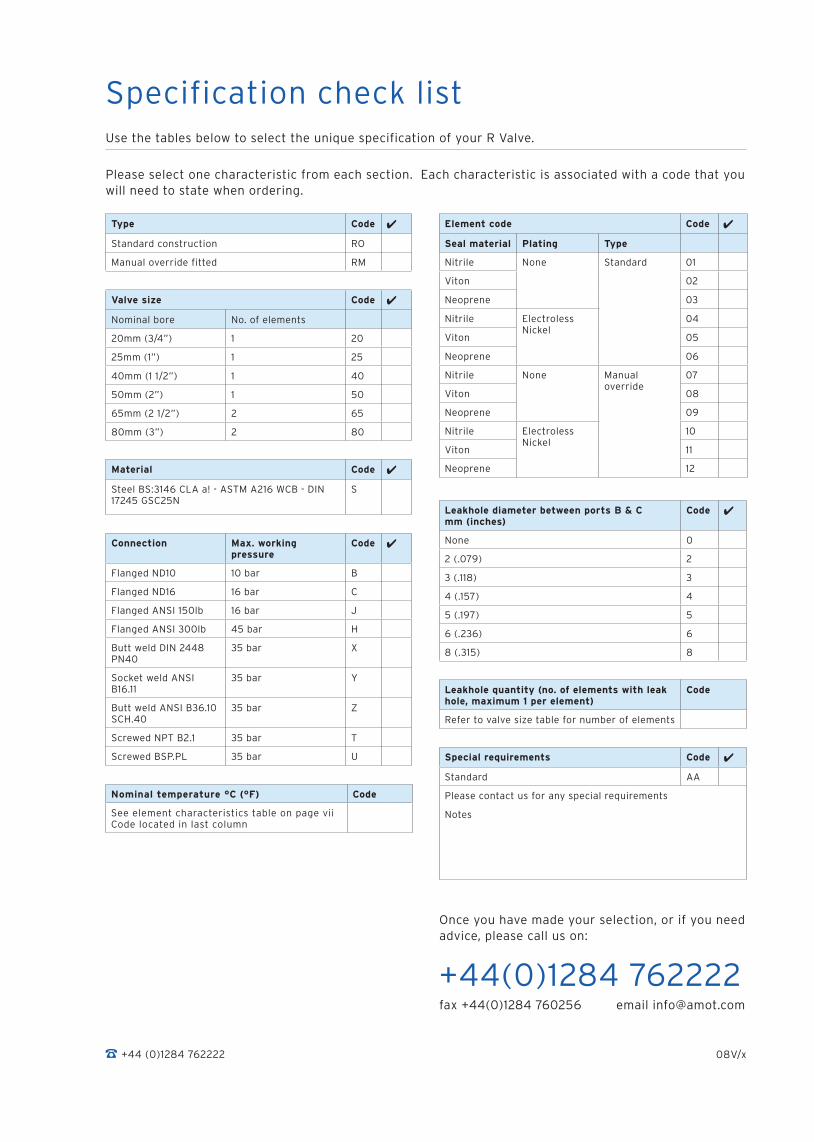
Specification check listUse the tables below to select the unique specification of your R Valve.
Type Code
Standard construction RO
Manual override fitted RM
Valve size Code
Nominal bore No. of elements
20mm (3/4”) 1 20
25mm (1”) 1 25
40mm (1 1/2”) 1 40
50mm (2”) 1 50
65mm (2 1/2”) 2 65
80mm (3”) 2 80
Material Code
Steel BS:3146 CLA a! - ASTM A216 WCB - DIN 17245 GSC25N
S
Connection Max. working pressure
Code
Flanged ND10 10 bar B
Flanged ND16 16 bar C
Flanged ANSI 150lb 16 bar J
Flanged ANSI 300lb 45 bar H
Butt weld DIN 2448 PN40
35 bar X
Socket weld ANSI B16.11
35 bar Y
Butt weld ANSI B36.10 SCH.40
35 bar Z
Screwed NPT B2.1 35 bar T
Screwed BSP.PL 35 bar U
Leakhole diameter between ports B & C mm (inches)
Code
None 0
2 (.079) 2
3 (.118) 3
4 (.157) 4
5 (.197) 5
6 (.236) 6
8 (.315) 8
Leakhole quantity (no. of elements with leak hole, maximum 1 per element)
Code
Refer to valve size table for number of elements
Special requirements Code
Standard AA
Please contact us for any special requirements
Notes
Please select one characteristic from each section. Each characteristic is associated with a code that you will need to state when ordering.
+44 (0)1284 762222 08V/x
Element code Code
Seal material Plating Type
Nitrile None Standard 01
Viton 02
Neoprene 03
Nitrile Electroless Nickel
04
Viton 05
Neoprene 06
Nitrile None Manual override
07
Viton 08
Neoprene 09
Nitrile Electroless Nickel
10
Viton 11
Neoprene 12
Nominal temperature °C (°F) Code
See element characteristics table on page vii Code located in last column
Once you have made your selection, or if you need advice, please call us on:
+44(0)1284 762222fax +44(0)1284 760256 email [email protected]

www.amot.com
Europe and Africa
AMOTWestern WayBury St EdmundsSuffolk, IP33 3SZEngland
Tel +44 (0) 1284 762222Fax +44 (0) 1284 760256Email [email protected]
AMOT Controls GmbHRondenbarg 2522525 HamburgGermany
Tel +49 (0) 40 8537 1298Fax +49 (0) 40 8537 1331Email [email protected]
Asia and Australasia
AMOT ShanghaiRm A8-671 Jiahua Business Center808 Hongqiao RoadShanghai 200030China
Tel +86 (0) 21 6447 9708Fax +86 (0) 21 6447 9718Email [email protected]
AMOT Singapore10 Eunos Road 8 #12-06Singapore Post CentreSingapore 408600
Tel +65 6293 4320Fax +65 6293 3307Email [email protected]
Americas
AMOT USA401 1st StreetRichmondCalifornia 94801-2906 USA
Tel +1 (510) 307 8300 Fax +1 (510) 234 9950 Email [email protected]
AMOT USA 8460 North Eldridge ParkwayHoustonTexas 77041USA
Tel: +1 (281) 970 8268Fax +1 (281) 671 2160Email [email protected]