Embed Size (px)
Citation preview

NAVAL POSTGRADUATE
SCHOOL
MONTEREY, CALIFORNIA
MBA PROFESSIONAL REPORT
Analysis of Using Fleet Readiness Centers
Vice Civilian Contractors for Aircraft Modification Work
By: Bryan T. McKernan, and
R. Erik Herrmann December 2008
Advisors: Ken Euske and
Becky Jones
Approved for public release; distribution is unlimited.

THIS PAGE INTENTIONALLY LEFT BLANK

i
REPORT DOCUMENTATION PAGE Form Approved OMB No. 0704-0188 Public reporting burden for this collection of information is estimated to average 1 hour per response, including the time for reviewing instruction, searching existing data sources, gathering and maintaining the data needed, and completing and reviewing the collection of information. Send comments regarding this burden estimate or any other aspect of this collection of information, including suggestions for reducing this burden, to Washington headquarters Services, Directorate for Information Operations and Reports, 1215 Jefferson Davis Highway, Suite 1204, Arlington, VA 22202-4302, and to the Office of Management and Budget, Paperwork Reduction Project (0704-0188) Washington DC 20503. 1. AGENCY USE ONLY (Leave blank)
2. REPORT DATE December 2008
3. REPORT TYPE AND DATES COVERED MBA Professional Report
4. TITLE AND SUBTITLE Analysis of Using Fleet Readiness Centers Vice Civilian Contractors for Aircraft Modification Work 6. AUTHOR(S) Bryan T. McKernan and R. Erik Herrmann
5. FUNDING NUMBERS
7. PERFORMING ORGANIZATION NAME(S) AND ADDRESS(ES) Naval Postgraduate School Monterey, CA 93943-5000
8. PERFORMING ORGANIZATION REPORT NUMBER
9. SPONSORING /MONITORING AGENCY NAME(S) AND ADDRESS(ES) Fleet Readiness Center Southwest Box 357058 San Diego, CA 92135-7058
10. SPONSORING/MONITORING AGENCY REPORT NUMBER
11. SUPPLEMENTARY NOTES The views expressed in this thesis are those of the author and do not reflect the official policy or position of the Department of Defense or the U.S. Government. 12a. DISTRIBUTION / AVAILABILITY STATEMENT Approved for public release; distribution is unlimited
12b. DISTRIBUTION CODE
13. ABSTRACT (maximum 200 words) Fleet Readiness Center Southwest (FRCSW) conducts maintenance on various aircraft platforms. In
addition to regular aircraft overhauls, FRCSW has the capacity to perform aircraft modifications, which are currently completed by contractors. This project examines why the FRC’s are not getting more CH-53E modification work when they have the capacity and capability to complete the work. This project uses FRCSW as a case study to address the issue. Interviews were conducted with the heads of Multi-line Division within FRCSW in San Diego, California and the Commander of FRC’s and the H-53 Assistant Program Manager for Logistics at Naval Air Systems Command (NAVAIR), Patuxent River, Maryland. The results of these interviews provided an assessment of the actions taken to reduce inefficiencies and non-value added activities and insight into how NAVAIR selects between contractors and FRC’s to complete modification work. The data reveal that FRCSW has the capacity to complete modification work on CH-53 aircraft without schedule slippage. Also, a comparison of labor rate, schedule, and location of work, demonstrates how much more expensive FRCSW is and why NAVAIR chooses the lower cost contractor to complete modification work.
15. NUMBER OF PAGES
84
14. SUBJECT TERMS Fleet Readiness Center Southwest, NAVAIR, PMA-261, CH-53 Modifications
16. PRICE CODE
17. SECURITY CLASSIFICATION OF REPORT
Unclassified
18. SECURITY CLASSIFICATION OF THIS PAGE
Unclassified
19. SECURITY CLASSIFICATION OF ABSTRACT
Unclassified
20. LIMITATION OF ABSTRACT
UU NSN 7540-01-280-5500 Standard Form 298 (Rev. 2-89) Prescribed by ANSI Std. 239-18

ii
THIS PAGE INTENTIONALLY LEFT BLANK

iii
Approved for public release; distribution is unlimited
ANALYSIS OF USING FLEET READINESS CENTERS VICE CIVILIAN CONTRACTORS FOR AIRCRAFT MODIFICATION WORK
Bryan T. McKernan, Major, United States Marine Corps R. Erik Herrmann, Captain, United States Marine Corps
Submitted in partial fulfillment of the requirements for the degree of
MASTER OF BUSINESS ADMINISTRATION
from the
NAVAL POSTGRADUATE SCHOOL December 2008
Authors: _____________________________________
Bryan T. McKernan _____________________________________
R. Erik Herrmann Approved by: _____________________________________
Ken J. Euske, Lead Advisor _____________________________________ Becky Jones, Support Advisor _____________________________________ Terry Rea, CAPT USN, Acting Dean
Graduate School of Business and Public Policy

iv
THIS PAGE INTENTIONALLY LEFT BLANK

v
ANALYSIS OF USING FLEET READINESS CENTERS VICE CIVILIAN CONTRACTORS FOR AIRCRAFT MODIFICATION
WORK
ABSTRACT
Fleet Readiness Center Southwest (FRCSW) conducts maintenance on various
aircraft platforms. In addition to regular aircraft overhauls, FRCSW has the capacity to
perform aircraft modifications, which are currently completed by contractors. This
project examines why the Fleet Readiness Centers (FRCs) are not getting more CH-53E
modification work when they have the capacity and capability to complete the work.
This project uses FRCSW as a case study to address the issue. Interviews were
conducted with the heads of Multi-line Division within FRCSW in San Diego, California
and the Commander of FRCs and the H-53 Assistant Program Manager for Logistics at
Naval Air Systems Command (NAVAIR), Patuxent River, Maryland. The results of
these interviews provided an assessment of the actions taken to reduce inefficiencies and
non-value added activities and insight into how NAVAIR selects between contractors and
FRCs to complete modification work. The data reveal that FRCSW has the capacity to
complete modification work on CH-53 aircraft without schedule slippage. Also, a
comparison of labor rate, schedule, and location of work, demonstrates how much more
expensive FRCSW is and why NAVAIR chooses the lower cost contractor to complete
modification work.

vi
THIS PAGE INTENTIONALLY LEFT BLANK

vii
TABLE OF CONTENTS
I. INTRODUCTION........................................................................................................1 A. PURPOSE OF THIS STUDY .........................................................................1 B. BACKGROUND ..............................................................................................1 C. RESEARCH QUESTIONS.............................................................................2
1. Primary Question.................................................................................2 2. Secondary Question .............................................................................2
II. FLEET READINESS CENTER SOUTHWEST ......................................................3 A. THE TRADITIONAL THREE LEVELS OF MAINTENANCE ...............3
1. Organizational......................................................................................3 2. Intermediate .........................................................................................4 3. Depot .....................................................................................................4
B. UNITED STATES CODE TITLE 10.............................................................5 C. BRAC 2005 .......................................................................................................6 D. NADEP NORTH ISLAND..............................................................................9
1. FRCSW Programs .............................................................................10 a. Components Program .............................................................10 b. E-2/C-2 Program.....................................................................11 c. F/A-18 Program ......................................................................11 d. Manufacturing Program ........................................................11 e. Engineering and Logistics Program ......................................11 f. Multi-Line Program................................................................12 g. Field Service/Voyager Repair Program .................................12
III. AIRSPEED CONCEPT.............................................................................................13 A. PROBLEM IDENTIFICATION AND SOLUTION (ENTERPRISE
AIRSPEED)....................................................................................................13 B. THEORY OF CONSTRAINTS....................................................................13 C. THE LEAN MODEL.....................................................................................15
1. Quick Hitters ......................................................................................19 D. SIX SIGMA ....................................................................................................19 E. COMPARISON OF THE THREE IMPROVEMENT PROGRAMS ......21 F. PITFALLS......................................................................................................22
IV. AIRSPEED INTEGRATION AT MULTI-LINE ...................................................23 A. ISSUES............................................................................................................23
1. Customer Focused Requirements.....................................................23 2. Where to Start ....................................................................................23 3. Buy In..................................................................................................24
B. LEAN IMPLEMENTATION AT FRCSW .................................................24 1. Point of Use Tooling/Publications/Pre-expendable Bins ................26 2. Kits ......................................................................................................26 3. Standard Work...................................................................................27

viii
4. Cell Development ...............................................................................28 C. MULTI-LINE CELL DEVELOPMENT.....................................................28
1. Working Cell # 1 - Induction ............................................................29 2. Working Cell # 2 - Disassembly........................................................29 3. Working Cell # 3 - Structures ...........................................................29 4. Working Cell # 4 - Assembly.............................................................30 5. Working Cell # 5 - Final Assembly...................................................30
D. BENEFITS OF AIRSPEED..........................................................................31
V. PROGRAM MANAGEMENT AIR VIEWPOINT ................................................35 A. PROGRAM MANAGEMENT AIR (PMA) ................................................35
1. Program Managers Responsibilities ................................................35 2. Modification Plan...............................................................................36 3. PMA Constraints ...............................................................................36 4. Supplemental and Global War on Terrorism Money ....................37
B. MODIFICATION PROCESS.......................................................................37 1. Modification Kits ...............................................................................38 2. Completion of Modification Installations ........................................38 3. Decision on Installer ..........................................................................38
a. Labor Rates .............................................................................39 b. Schedule ..................................................................................39 c. Location of Work ....................................................................40
C. SUMMARY ....................................................................................................40
VI. COMPARISON OF CONTRACTOR VS. FRCSW...............................................41 A. FACTORS AFFECTING CHOICE OF PROVIDER................................41
1. Labor Rates ........................................................................................41 2. Schedule ..............................................................................................41 3. Location of Work ...............................................................................42 4. Perceptions..........................................................................................43
VII. CONCLUSIONS AND RECOMMENDATIONS...................................................47 A. INTRODUCTION..........................................................................................47 B. PRIMARY QUESTION ................................................................................48
1. Is It in the Best Interest of the United States Marine Corps to Utilize Fleet Readiness Centers to Conduct More CH-53E Modification Work?...........................................................................48
C. SECONDARY QUESTION ..........................................................................48 1. Can the FRCs Conduct Modifications in Conjunction with a
PMI Event in the 180-day TAT? ......................................................48 D. RECOMMENDATIONS...............................................................................49
1. PMA’s Need to Reexamine the FRC’s Capabilities........................49 2. PMA-261 Should Have FRCSW and FRCE Install All
Available Modifications in Conjunction with the 24 Annually Scheduled PMI Events.......................................................................49
E. FURTHER ANALYSIS QUESTIONS ........................................................49

ix
1. What is the Cost to the Fleet to Have an Aircraft Out of Service for One Day? .........................................................................49
APPENDIX.............................................................................................................................51
LIST OF REFERENCES......................................................................................................61
INITIAL DISTRIBUTION LIST .........................................................................................65

x
THIS PAGE INTENTIONALLY LEFT BLANK

xi
LIST OF FIGURES
Figure 1. Naval Aviation Enterprise (NAE) Fleet Readiness Centers ..............................8 Figure 2. FRCSW Organization Chart. ...........................................................................12 Figure 3. Cell Layout.......................................................................................................18 Figure 4. FY08 CH-53E Turnaround Time.....................................................................25 Figure 5. Artisan Time Off Aircraft is Waste. ................................................................32 Figure 6. Reduced Off Aircraft Time After Lean. ..........................................................32

xii
THIS PAGE INTENTIONALLY LEFT BLANK

xiii
LIST OF TABLES
Table 1. Comparison of Improvement Programs...........................................................21 Table 2. Work Sequence Breakdown.............................................................................27 Table 3. Comparison of Contractor vs. FRC .................................................................45 Table 4. Master Work Sequence Schedule Example .....................................................52 Table 5. Structures Examination & Evaluation 8-Day Sequence Example...................53 Table 6. Assembly 18-Day Sequence Example .............................................................55 Table 7. Final Assembly 18-Day Sequence Example....................................................56 Table 8. Test Line 18-Day Sequence Example..............................................................59

xiv
THIS PAGE INTENTIONALLY LEFT BLANK

xv
ACKNOWLEDGMENTS
We would like to take this opportunity to thank our Co-Advisors, Professor
Kenneth J. Euske and Becky Jones, for mentoring us through this process. We are
grateful for the time, effort, and guidance that they provided in support of this project.
We would also like to thank the FRCSW Commanding Officer, Capt Mike Kelly,
for his unselfish support and the unlimited access he provided to his command. A special
thanks to FRCSW Multi-line, Dave Kelly, and Ron Cobb for their candid discussions and
insights toward the development of our project.
A final thank you to RDML Paul Grosklags, Commander Fleet Readiness
Centers, and LtCol Henry Hess, PMA-261 H-53D/E APML, for providing us time and
insight into how the modification process works for their particular airframe.

xvi
THIS PAGE INTENTIONALLY LEFT BLANK

1
I. INTRODUCTION
A. PURPOSE OF THIS STUDY
The purpose of this study is to analyze why the FRC’s are not receiving more CH-
53E modification work when they have the capacity and capability to complete the work.
B. BACKGROUND
The service life of the CH-53E is 54 months. At the end of 54 months, the
aircraft goes out of a reporting status and into its respective FRC for a Planned
Maintenance Interval (PMI) event. Once the PMI event is completed, the aircraft is sent
back to the operational unit, and immediately enters into another period of maintenance
to be fit with modifications. Currently, contractors complete modifications and as a
result, the aircraft is unavailable for use for a longer period of time. Although FRCSW
possesses the capabilities to conduct the aircraft modification in conjunction with the
PMI event, this is not occurring for the majority of modifications being installed. For
instance, FRCSW is conducting two modifications in conjunction with a PMI event. One
modification involves the replacement of Kapton wiring inside the aircraft and the other
modification removes and replaces the tail boom assembly.1
This project examines the CH-53 helicopter, for which FRCSW provides depot
level maintenance. The cost NAVAIR incurs by having contractors perform the upgrades
rather than FRCSW is reported. Also analyzed is whether a cost advantage by employing
FRCSW for this function exists. In addition, the advantages to the fleet of having an
aircraft back in the inventory sooner with all upgrades performed by FRCSW vice using
contractors is examined. The authors traveled to FRCSW to gather data on how the
multi-line operated and how they have improved on their processes. They also traveled
to Patuxent River, Maryland to interview PMA-261 to ascertain its process for choosing
contractors.
1 Dave Kelly, Interview by Bryan McKernan and Erik Herrmann, Fleet Readiness Center Southwest,
San Diego, California, August 11, 2008.
2
C. RESEARCH QUESTIONS
1. Primary Question
Is it in the best interest of the United States Marine Corps to utilize Fleet
Readiness Centers to conduct more CH-53E modification work?
2. Secondary Question
Can the FRC’s conduct modifications in conjunction with a PMI event in 180-day
TAT?

3
II. FLEET READINESS CENTER SOUTHWEST
A. THE TRADITIONAL THREE LEVELS OF MAINTENANCE2
The organizational, intermediate, and depot levels of aviation maintenance are
distinctive in organization, mission and concept. Listed below is a brief synopsis of each
level’s responsibility to the Naval Aviation Maintenance Program.
1. Organizational
Organizational level (O-level) is performed by an operating unit on a day-to-day
basis in support of its own operations. The O-level’s maintenance mission is to maintain
assigned aircraft and aeronautical equipment in a Full Mission Capable (FMC) status
while continually improving the local maintenance processes. While O-level
maintenance may be done by intermediate (I-level) or depot level (D-level) activities, O-
level maintenance is usually accomplished by maintenance personnel assigned to aircraft-
reporting custodians.3 Aircraft-reporting custodians are responsible for the
administrative reporting and maintenance of weapons systems in their custody.
Squadrons, such as, VFA-34, VF-101, HM-14, HSC-26 are examples of O-level activities
(or units). These O-level activities are assigned aircraft, equipment, and personnel that
provide direct support to the warfighter. These maintenance functions generally are
grouped under the categories of inspections, servicing, handling, on-equipment repairs,
preventive maintenance, and upkeep.4
2 Section A with minor modification is drawn directly from, F. R. Clemmons and, H. M. Falconieri,
“Analysis of Fleet Readiness Center Southwest Concept Integration: New-Employee Orientation and Communications Process,” (MBA Project, Naval Postgraduate School, 2007), 3-4.
3 Naval Air Systems Command, “COMNAVAIRFOR INSTRCUTION 4790.2,” Naval Aviation Maintenance Program (NAMP), vol. 1, Naval Air Systems Command, (February 1, 2005), http://logistics.navair.navy.mil/4790/library/VOL_1.pdf (accessed March 11, 2007).
4 Ibid.

4
2. Intermediate
The I-level’s mission is to enhance and sustain the combat readiness and mission
capability of supported activities by providing quality and timely material support at the
nearest location with the lowest practical resource expenditure.5 I-level maintenance
consists of on-and off-equipment material support. On-equipment maintenance is
conducted on the aircraft/end-item. On-equipment maintenance includes the repair of
installed engines, calibration of systems, or repair of support equipment. Off-equipment
maintenance is conducted when the component/item is removed from the aircraft/end-
item and repaired at the facility. Off-equipment maintenance includes the processing of
aircraft components; incorporation of technical directives; provision of technical
assistance; the manufacture of selected components, liquids, or gases; and performance of
certain on-equipment repairs.6
3. Depot
The D-level’s maintenance is performed at or by the Naval aviation industrial
establishment to ensure continued flying integrity of airframes and flight systems during
subsequent operational service periods. D-level maintenance is also performed on
material requiring major overhaul of parts, assemblies, sub-assemblies, and end-items
beyond the capability of I-level. D-level maintenance includes manufacturing parts,
modifying, testing, inspecting, sampling, and reclamation.7 D-level maintenance
supports O-level and I-level maintenance by providing engineering assistance and
performing maintenance beyond O-level and I-level capabilities.
5 Naval Air Systems Command, “COMNAVAIRFOR INSTRCUTION 4790.2,” Naval Aviation
Maintenance Program (NAMP), vol. 1, Naval Air Systems Command, (February 1, 2005), http://logistics.navair.navy.mil/4790/library/VOL_1.pdf (accessed March 11, 2007).
6 Ibid. 7 Ibid.

5
B. UNITED STATES CODE TITLE 108
Title 10 of the U.S. Code provides the legislative foundation for depot-level
maintenance and the use of working capital funds for industrial type activities. The
section of Subtitle A, Part IV of Chapter 148 sets the requirement for depot-level
maintenance activities within the DoD. Sections 2460-2464, 2466-2467, 2469-2472 and
2474-2475, of Chapter 146 provide the elements of the legislation for depot-level
maintenance activities. The sections of Chapter 146 are as follows.
• define depot-level maintenance
• establish the scope of work
• establish the studies and reports requirements
• encourage public-private competition
• establish the requirements for converting to and from contracting workforce
• establish the requirement to maintain core logistics capabilities
• limit the amount of depot maintenance that can be contracted to private industry
• set the standard for managing DoD civilian employees
• allow depot-level maintenance activities to compete for other federal agency work
• authorize the Secretary of Defense (SECDEF) to designate Centers of Industrial and Technical Excellence
Section 2563, Chapter 152 allows depot maintenance activities to perform work
for private industry. Section 2687, Chapter 159 discusses base closures and realignments
and section 2208, Chapter 131 discusses working capital funds.
Title 10 provides legal justification, restrictions, opportunities, and requirements
for the military depot-level maintenance industry.
8 Section B & C with minor modifications is drawn directly from, T. Curran and, J. J. Schimpff, “An
Analysis of Factors Generating the Variance between the Budgeted and Actual Operating Results of the Naval Aviation Depot at North Island, California,” (MBA Project, Naval Postgraduate School, 2008), 5-8.

6
By providing the Armed Forces with a critical capacity to respond to the needs of
the Armed Forces for depot-level maintenance and repair of weapons systems and
equipment, the depot-level maintenance and repair activities of the DoD play an essential
role in maintaining the readiness of the Armed Forces.
C. BRAC 2005
There have been five Base Realignment and Closures (BRAC) rounds (in 1991,
1993, 1995, 1998 and 2005). BRAC 2005 was the driving force behind the reorganizing
and restructuring of Naval Aviation Maintenance into what it is today.9
A comprehensive assessment in support of BRAC decisions revealed that the
DoD maintained a 24 percent excess capacity in installations to support the future
forces.10 In his initial guidance to the DoD, then Secretary of Defense (SECDEF)
Donald Rumsfeld directed the DoD leaders to reconfigure the current infrastructure into
one, which maximizes both war fighting capability and efficiency.11 As a result, five
themes were developed:
• Support force transformation
• Rebase forces to address new threat, strategy, and force protection concerns
• Consolidate business-oriented support functions
• Promote joint and multi-Service basing
• Achieve savings (DoD, 2005)
The two themes the Naval Aviation Enterprise (NAE) directly supports are to
consolidate business-oriented support functions and achieve savings through restructuring
support functions and reduction of support personnel, land and facilities.12 To support
9 GAO Report, “Observations on Prior and Current BRAC Rounds,”
http://www.gao.gov/new.items/d05614 (accessed November 1, 2008). 10 “Base Closure and Realignment Report Part 1 of 2: Results and Process, vol. 1,” Department of
Defense, Washington, D.C., 2005. 11 Ibid. 12 Ibid.

7
the two themes, NAE adopted the objectives of reducing the number of maintenance
levels by integrating the depot-level maintenance and intermediate level-maintenance and
moving the integrated maintenance closer to the most populated fleet areas.
BRAC 2005 reorganization and restructuring of depot-level and intermediate-
level maintenance activities proposed the creation of six Fleet Readiness Centers (FRC)
and 13 satellite FRC sites. Naval Aviation Depot (NADEP) North Island and the
Aviation Intermediate Maintenance Department (AIMD) entities at North Island were
realigned under FRC Southwest. Figure 1 shows the Naval Aviation Enterprise FRC
layout as of April 2006.13 As depicted in this figure, the concentrations of maintenance
activities are located where the Navy’s aviation assets are concentrated.
13 J. Johns, “Naval Aviation Transformation Brief,” Defense Supply Center Richmond,
http://www.dscr.dla.mil/uuserweb/dscrl/alc.alc2006/ACL%202006%20Briefings/1%20(A-8.1)%20Services%20Senrio%20Panel%20John%20John.ppt#275.17.Slide17 (accessed December 15, 2007).

8
Figure 1. Naval Aviation Enterprise (NAE) Fleet Readiness Centers14
14 J. Johns, “Naval Aviation Transformation Brief.” Defense Supply Center Richmond,
http://www.dscr.dla.mil/uuserweb/dscrl/alc.alc2006/ACL%202006%20Briefings/1%20(A-8.1)%20Services%20Senrio%20Panel%20John%20John.ppt#275.17.Slide17 (accessed December 15, 2007).

9
D. NADEP NORTH ISLAND15
The depot-level maintenance functions of FRCSW are nearly as old as Naval
Aviation itself. In 1919, nine years after the start of Naval Aviation, the FRC began work
as an Assembly and Repair Department of the Naval Air Station at North Island. In
1969, the Assembly and Repair Department was renamed the Naval Air Rework Facility
(NARF). By 1987, the NARF was renamed the Naval Aviation Depot (NADEP) North
Island.16 As result of BRAC 2005, NADEP North Island was disestablished and
realigned into FRC Southwest.17
Recognized as an innovator in depot-level maintenance by the Office of Naval
Research’s Best Manufacturing Practices Program, FRCSW is the Navy’s primary west
coast aircraft repair and modification facility for mission essential fighter and rotary wing
aircraft for Navy and Marine Corps squadrons.18 As of December 2007, FRCSW
employed 4,371 people consisting of 3,494 civilian employees and 877 military
personnel. The mission of the Fleet Readiness Center Southwest is:
…CNAF’s [Commander Naval Forces] West Coast Aircraft Repair D21 [Depot to Intermediate] facility specializing in the support of Navy and Marine Corps aircraft and related systems. Through partnerships with industry, other government agencies and supporting aerospace organizations, FRC Southwest, North Island repairs and overhauls aviation systems.19
FRCSW performs repair and modifications work on F/A 18 Hornets and Super
Hornets, EA-6B Prowlers, E-2 Hawkeyes, C-2 Greyhounds, AV-8B Harriers, SH-60
15 Section D with minor modifications is drawn directly from T. Curran and J. J. Schimpff, “An
Analysis of Factors Generating the Variance between the Budgeted and Actual Operating Results of the Naval Aviation Depot at North Island, California,” (MBA Project, Naval Postgraduate School, 2008), 5-8.
16 Best Manufacturing Practices, “Naval Aviation (NAVAIR) Depot, North Island – San Diego, CA: Best Practices,” http://www/bmpcoe.org/bestpractices/internal/nadep/index.html (accessed November 20, 2007).
17 Joe Moore, “BRAC 2005; The New Integrated I&D Level Maintenance,” http://www.av8.org/brac-05 (accessed November 1, 2008).
18 Ibid. 19 Fleet Readiness Center Southwest, “Homepage,” http://www.frcsw.navy.mil/frcsw (accessed
November 30, 2007).

10
Seahawks and HH/MH-60s, AH-1 Cobras, UH/HH Hueys, and CH-53 Sea Stallions.
Additionally, FRCSW deploys Field Service Teams and Voyager Repair Teams to
deployed aviation squadrons, ships, and installations worldwide. The Field Service and
Voyager Repair Teams provide depot-level maintenance repair and modification for
aircraft, aviation structures, aircraft components, aircraft carrier catapult and arresting
gear systems, and aviation equipment and facilities on other ships.20 In 2007, FRCSW
deployed over 2,500 Field Service and Voyager Repair Teams, repaired and modified
approximately 285 aircraft, and manufactured over 50,000 aircraft components.
1. FRCSW Programs21
The FRCSW receives aircraft, engines and a multitude of components from
activities within the U.S., as well as forward deployed units, for maintenance,
modification and repair needed from normal operations or battle related damage.
Requests to manufacture new replacement items for components that can no longer be
repaired, refurbished or are not commercially available are also received from fleet units
as well as other DoD components. These demands are satisfied by the services provided
through one or more of the following seven FRCSW programs.22
a. Components Program
The components program at FRCSW has the capabilities to repair and
refurbish over 19,000 different types of Navy, Marine Corps aircraft components, supply
systems and DoD assets. The Components Department existed as a program within the
Depot prior to the merger. As a result of the FRC implementation, the AIMD repair
capabilities and the Depot artisan (worker) skills are integrated into a single organization.
20 Fleet Readiness Center Southwest, “Homepage,” http://www.frcsw.navy.mil/frcsw (accessed
November 30, 2007). 21 Section 1 with minor modifications is drawn directly from J. F. Montes, “Organizational Design
Analysis of Fleet Readiness Center Southwest Components Department,” (MBA Project, Naval Postgraduate School, 2007), 7-10.
22 Fleet Readiness Center Southwest, “Homepage,” http://www.frcsw.navy.mil/frcsw (accessed November 30, 2007).

11
The new organization has personnel, equipment and facilities specialized in the repair
and refurbishment of Avionics, Aircraft Supports and Surfaces, Instruments and
Generators, Landing Gear and Hydraulics components for units ashore and afloat.
b. E-2/C-2 Program
The E-2/C-2 Program is comprised of five groups that include 1) PMI One
and Two for repair and refurbishing (PMI-1/2), 2) PMI-3/Service Life Extension Program
(SLEP)/Rewire (C-2), 3) In-Service Repair (ISR), 4) Foreign Military Sales (FMS), and
5) E-2 Super Modules.
c. F/A-18 Program
The F/A-18 Program supports PMI-1/-2 Special Rework/Crash Damage
Repair (SR/CD) and Center Barrel Replacement Plus (CBR+).
d. Manufacturing Program
The Manufacturing Program has machining, sheet metal fabrication,
tube/hose/duct repair, foundry, welding and heat treatment capabilities that support the
aircraft and helicopter rework programs as well as the overhaul of the LM2500 marine
gas turbine engine used on surface naval ships. This department also manufactures and
repairs over 150 different configurations of mobile VANS, large steel containers with
special equipment that support deployed Marine Corps Units.
e. Engineering and Logistics Program
The Engineering and Logistics Program is part of the In-Service Support
Center (ISSC) and consists of a full Materials Laboratory and the Navy Primary
Standards Laboratory (NPSL). This program is responsible for developing the safest,
most reliable and cost-effective engineering solutions needed to meet or exceed the
repair, refurbishment and modifications requirement for products.

12
f. Multi-Line Program
The Multi-Line Program supports PMI-1/-2 for UH-1/HH-1 Huey, CH-53
Super Stallion, AH-1W Super Cobra and SH-60/MH-60/HH-60 Seahawk helicopters for
the Navy and Marine Corps.
g. Field Service/Voyager Repair Program
The field Service/Voyager Repair Program is comprised of Voyager
Repair teams, Field Service teams, paint/finish and surface/structural repair support for
AV-8B Harrier aircraft in Yuma, Arizona.
Figure 2. FRCSW Organization Chart.23
23 Preliminary organizational chart provided by FRCSW Staff, July 2007.

13
III. AIRSPEED CONCEPT
A. PROBLEM IDENTIFICATION AND SOLUTION (ENTERPRISE AIRSPEED)
Recognizing the need to reduce the cost of doing business, improve productivity,
and increase customer satisfaction, the Naval Air Systems Command (NAVAIR)
implemented the “AIRSpeed” program. The program’s intent was to create an
environment of continuous process improvement, optimize maintenance and supply
activities to meet operations, and eliminate sub-optimization by using a common set of
industry proven tools.24
The AIRSpeed concept is not designed around available work hours. The
schedule is what drives an airplane through the process, not the amount of workload.25
The schedule is derived from the total number of airplanes that need to be completed
during the year and the total number of workdays available. The process time is the same
whether the amount of effort to complete the job is five hours or five hundred hours.26 If
there is additional work (hours) on the airplane that needs to be completed, the rate of
effort is increased rather than the timeline. Productive effort can be increased when
waste has been reduced. The tools FRCSW has used to achieve better efficiency are a
mixture of Theory of Constraints (TOC), Lean, and Six Sigma. These tools focus
attention on eliminating waste in processes and maintaining process control.
B. THEORY OF CONSTRAINTS
In the mid-80s, Dr. Elijahu Goldratt, developed TOC. This management tool
focuses on reducing costs and improving productivity by identifying and removing
24 Naval Aviation Enterprise, “Enterprise AIRSpeed,” http://www.cnaf.navy.mil/airspeed (accessed
August 15, 2008). 25 Dave Kelly, Interview by Bryan McKernan and Erik Herrmann, Fleet Readiness Center Southwest,
San Diego, California, August 11, 2008. 26 Ibid.

14
“constraints” in a system. A constraint is a factor that limits an organization’s ability to
achieve its goal.27 TOC allows the change process to employ five thinking process tools.
• Current Reality Tree: Using experienced and involved individuals, it identifies the root causes of a problem (what to change)
• Evaporating Cloud: Identifies a solution to the core problem and uncovers the factors that created the problem
• Future Reality Tree: Identifies what is missing from the proposed solution before implementing changes (what to change to)
• Prerequisite Tree: Identifies the intermediate steps and obstacles that need to be taken to reach the new goal or process (how to cause change)
• Transition Tree: Identifies the actions (implementation plan) needed to take, given the current situation, to achieve the intermediate goals (as identified in the Prerequisite Tree)28
TOC uses the terms bottleneck, drum, rope, and buffer to explain the output of a
plant. The “drum” is essentially the bottleneck that paces the plant. Increase the drum
and the bottleneck diminishes. Bottleneck idle time is reduced by having a “buffer,”
which is inventory that is in front of the bottleneck. The communication system within
the plant is called the “rope.” Inventory requirements at the bottleneck need to be
communicated back to the material release point in order to control production. Remove
bottlenecks and production increases.
The TOC Process can be broken down into five steps.
Step 1: Identify the constraint
Step 2: Focus on how to get more production at the constraint within the existing
capacity limitations.
Step 3: Keep materials needed next from sitting idle in a queue at a non-
constrained resource.
27 B. Motley, “Using Theory of Constraints (TOC) to Improve Quality, Cost and Productivity,”
Defense Systems Management College, June 2004. 28 Ibid.
15
Step 4: If, after fully exploiting this process and it is still not possible to produce
enough product to meet the demand, find other ways to increase capacity.
Step 5: Go back to step 1.29
There are multiple benefits to applying the TOC to a DoD program. For instance,
TOC can help reduce cost and cycle time and it can help to improve quality,
responsiveness, and performance.30
C. THE LEAN MODEL
The lean model is a systematic approach to identifying and eliminating waste
(non-value-added activities) through continuous improvement by focusing on customer
needs to deliver goods and services.31 The lean model encompasses a set of principles,
concepts, and techniques designed to pursue the elimination of waste continually while
producing an efficient just-in-time production system that will deliver six things to
customers.
• Exactly what they need
• When they need it
• In the quantity they need
• In the right sequence
• Without defects
• At the lowest possible cost32
Waste is anything other than the minimum amount of equipment, materials, parts,
space, and the worker’s time, which are absolutely essential to add value to the product.33
Some common examples of waste in a plant are listed as follows.
29 B. Motley, “Using Theory of Constraints (TOC) to Improve Quality, Cost and Productivity,” Defense Systems Management College, June 2004.
30 Ibid. 31 Dynamic Research Corporation and Clemson University, “Lean Pathways, Lean Overview of CVN
Applications,” Navy MANTECH, 2003. 32 Ibid. 33 Ibid.

16
• Overproduction
• Waiting
• Transportation of parts/material/tooling
• Non-value-added processing
• Excess finished inventory
• Defects
• Excess people motion
• Underutilized people
• Motion
The lean model is designed to start with the customer. First, internal and external
customers need to be defined. Next, delivery needs to be on demand, where and when
the customer wants the product. The Lean Model builds what is sold and supplies what is
consumed. It is a system that is flexible in its responses and produces a balanced flow.
Continuous improvement is the goal of Lean. The building blocks Lean relies on are as
follows.
• TAKT time - the maximum amount of time allowed to produce a product in order to meet demand
• Pull/Kanban - a signaling system to trigger action
• Just-in-time (JIT) - an inventory strategy to improve the return on investment by reducing in-process inventory and its associated carrying costs
• Cellular/Flow - is the linking of manual and machine operations into the most efficient combination of resources to maximize value-added content
• Batch Reductions - meeting the customer’s demands while at the same time reducing inventory carrying costs, work in progress, and lead or cycle time
• Quality at source - requires every employee to inspect their work, reducing defective products
• Quick Changeover - a process to reduce the amount of production time lost while a machine is down for changeovers
• Total Productive Maintenance (TPM) - is a methodology for proactive and progressive maintenance, which analyzes the overall equipment effectiveness

17
• Teams - innovative teams are able to accomplish more than an innovative individual. Cross-section teams engage all levels of the company and are able to respond to a broad spectrum of situations
• Standardized Work - enables a company wide communication of best practices. It also creates an environment that is flexible and able to new technologies and methods as they arise.
• Point Of Use Storage (POUS) - places material, tools, and equipment where and when it is needed in an orderly fashion
• Value Stream Mapping - involves drawing out schematics of processes in order to eliminate non-value added activities, reduce cycle time, enhance quality, and to increase affordability
• 5S - a way of organizing and managing the workspace and work flow with the intent to improve efficiency by eliminating waste and improving flow34
The lean model incorporates the 5S theory, which simply equates to good
housekeeping. The 5Ss are Sorting (proper arrangement), Simplifying (orderliness),
Sweeping (cleanliness), Standardize (cleanup) and Self-discipline (discipline).35 Visual
controls are a key ingredient in the building blocks of Lean. When walking into a place
of work, proper Lean implementation should visually show the following.
• What the process is
• Who the customers and suppliers are
• What the deliverables are
• Where and what resources are being used in the process, and;
• An effective measurement system is in place
The purpose of visual controls are listed below.
• Show how to do the job (standard operations)
• Show how things are used
• Show where things are stored
• Control inventory storage levels
• Show production status
34 RIMES, “What is a Lean Enterprise?” www.rimes.org (accessed October 1, 2008). 35 Dynamic Research Corporation and Clemson University, “Lean Pathways, Lean Overview of CVN
Applications,” Navy MANTECH, 2003.

18
• Indicate when people need help
• Mistake-proof the operation36
The lean model principles are based on quality, cost and delivery. By creating a
system, which is intolerant of production abnormalities, quality improves. Waste is
minimized in production thus reducing cost and efficient delivery decreases lead times.37
Lean production lines often use work cells to operate in a more efficient manner. A cell
is a work center that incorporates everything required in order to process the product.
Cells can create an environment for continuous flow manufacturing. Throughput is
increased by utilizing cells. Figure 3 shows the worker in Part A having to move from
raw materials (RM) in one station to subsequent stations to accomplish the task and have
a finished good (FG). When tasks are organized into cells, as shown in Part B, efficiency
results.
Figure 3. Cell Layout.38
36 Dynamic Research Corporation and Clemson University, “Lean Pathways, Lean Overview of CVN
Applications,” Navy MANTECH, 2003. 37 Ibid. 38 Ibid.

19
1. Quick Hitters
Incorporating Lean tools in any organization can be a timely process. Many items,
however, can be integrated quickly in order to enhance an operation and eliminate waste.
Examples of this type of Lean engagement are called Quick Hitters. Quick Hitters are
items that can be addressed quickly with little or no cost. Examples are listed as follows.
• Centralized Tooling
• Color coded parts
• Shelving labels
• Quality Matrix Charts
• Pick Lists
• Visual aids
• Machine Maintenance Log
• Parking Lots
• Training Manuals
• Internet/Interoffice email39
Lean eliminates waste within an organization, which not only increases the
customer’s satisfaction level, but also increases the bottom line for the organization.
Lean principles enable individuals working on the floor the ability to implement their
ideas for process improvement resulting in eliminating waste. This is good for
management because it improves morale and productivity by providing the worker on the
floor a sense of ownership in the process that said worker helped to create.
D. SIX SIGMA
Originally developed by Motorola, “Six Sigma” seeks to identify and remove the
causes of defects and errors in manufacturing and business processes.40 Defects are
defined in the Six Sigma theory as anything that could lead to customer dissatisfaction.
39 Dynamic Research Corporation and Clemson University, “Lean Pathways, Lean Overview of CVN
Applications,” Navy MANTECH, 2003. 40 J. Antony, “Pros and Cons of Six Sigma: An Academic Perspective,” Onesixsigma.com,
http://onesixsigma.com/node/7630 (accessed September 8, 2008).

20
By improving processes, organizations can reduce costs, keep customers satisfied and
thus, increase the potential for profitability. The term Six Sigma comes from a field of
statistics. The term Six Sigma process comes from the notion that if one has six standard
deviations (sigma) between the mean of a process and the nearest specification limit,
there will be practically no items that fail to meet the specifications.41 Processes that
operate with “Six Sigma quality” over the short term are assumed to produce long-term
defect levels below 3.4 defects per million opportunities or 99.9997 per cent efficiency.42
Six Sigma evolved from years of quality control and improvement process
methodologies, but differs from its predecessors in four distinct ways.
• A clear focus on achieving measurable and quantifiable financial returns from any Six Sigma project
• An increased emphasis on strong and passionate management leadership and support
• A special infrastructure of “Champions,” “Master Black Belts,” “Black Belts,” etc. to lead and implement the Six Sigma approach
• A clear commitment to making decisions on the basis of verifiable data, rather than assumptions and guesswork43
Fortune 500 companies, such as Honeywell International, and General Electric
have adopted Six Sigma. Its usage in the DoD is growing in order to increase product
reliability and reduce cycle time. AIRSpeed uses Six Sigma theory to try and improve
the entire process by reducing the variation of multiple elements, inputs, and sub
processes. This assumption is proven through a rigid and structured investigation
methodology. The Six Sigma methodology includes five steps.
• Define: who is the customer and what are their problems? What are the key characteristics important to the customer and what processes support those characteristics?
• Measure: key characteristics are categorized, measurement systems are verified and data are collected
41 G. Tennant, Six Sigma: SPC and TQM in Manufacturing and Services (Gower Publishing, Ltd.,
2001), 25. 42 Motorola University, “Six Sigma Dictionary,”
http://www.motorola.com/content.jsp?globalObjectId=3074-5804 (accessed September 8, 2008). 43 J. Antony, “Pros and Cons of Six Sigma: An Academic Perspective,” Onesixsigma.com,
http://onesixsigma.com/node/7630 (accessed September 8, 2008).

21
• Analyze: convert raw data into information that provides insights into the process. Identify the fundamental and most important causes of the defects or problems.
• Improve: develop solutions and make changes to the process. Results of changes are seen in the measurements.
• Control: the process is monitored to assure no unexpected changes occur44
E. COMPARISON OF THE THREE IMPROVEMENT PROGRAMS
Any number of techniques may be used to increase efficiency and effectiveness in
production processes. Below is a summary of the three concepts used by FRCSW and
selected strengths and weaknesses of each.
Program Theory of Constraints Lean Six Sigma Theory Manage Constraints Remove Waste Reduce Variation Application Guidelines 1. Identify Constraint
2. Exploit Constraint 3. Subordinate Processes 4. Elevate Constraint 5. Repeat Cycle
1. Identify Value 2. ID Value Stream 3. Flow 4. Pull 5. Perfection
1. Define 2. Measure 3. Analyze 4. Improve 5. Control
Focus System Constraints Flow Focused Problem Focused Assumptions Emphasis on speed and
volume. Uses existing systems. Process interdependence.
Waste removal will improve business performance. Many small improvements are better than systems analysis.
A problem exists. Figures and numbers are valued. System output improves if variation in all processes is reduced.
Primary Effect Fast Throughput Reduced Flow Time Uniform Process Output Secondary Effects Less inventory/waste.
Throughput cost accounting. Throughput-performance measurement system. Improved quality.
Less variation. Uniform output. Less inventory. New accounting system. Flow-performance measure for managers. Improved quality.
Less waste. Fast throughput. Less inventory. Fluctuation-performance measures for managers improved quality.
Criticisms Minimal worker input. Data analysis not valued.
Statistical or system analysis not valued.
System interaction not considered. Processes improved independently
Table 1. Comparison of Improvement Programs.45
44 P. D. Harnden, “Integrating Lean and Six Sigma and AIRSpeed within the NAVAIR 4.1
Organizational Improvement Efforts,” (White Paper, Commonwealth Centers for High Performance Organizations, 2004).
45 Ibid.

22
F. PITFALLS
AIRSpeed integration needs to be adopted and fostered by all levels within the
organization. The tools that AIRSpeed utilizes (TOC, Lean, “Six Sigma”) are building
blocks that need to be continually reassessed in order to maintain the maximum amount
of output a particular process/system can produce. The limits to AIRSpeed are that
processes can only be improved to a certain level of efficiency and must be adapted
differently depending on the system. Failure to achieve this will result in minimal impact
to efficiency. In the case of FRCSW’s multi-line, two workers may only utilize the
aircraft cockpit at a time. Despite having multiple workers capable of working on the
cockpit, the organization can do nothing to change the confines of the cockpit space.
Therefore, efficiency is unlikely to increase any more than what has been achieved by
keeping two people working in this space at one time.

23
IV. AIRSPEED INTEGRATION AT MULTI-LINE
A. ISSUES
FRCSW needed to review their processes because they were not meeting their
customer’s time requirements. They were taking too long and were inefficiently using
resources, which ultimately increased costs. The CH-53E team, within the Multi-line
division, agreed that they needed to a better job.
1. Customer Focused Requirements
The initial questions addressed in implementing the AIRSpeed transformation
process were, “What does the customer expect?” and “how many aircraft does the
customer want completed each year by the depot?” The answer to the question drives the
production process. The math used within AIRSpeed was very simple. If the fleet
requires 10 CH-53Es delivered each year from the Depot and there are 250 workdays
available, then the multi-line division needed to produce a completed aircraft every 25
days.
2. Where to Start
Once the multi-line division identified their annual objectives and aircraft
requirements, they studied how their current production line operated. The FRCSW
multi-line division realized that before they could start Six Sigma, they needed to focus
more on Lean. The Six Sigma concept does not work unless the processes under control.
This became priority number one. FRCSW’s multi-line personnel started to identify
where they could apply Lean techniques to make tangible improvements. Their first step
was to generate a value stream map of the CH-53E line from a 50,000-foot perspective.
Simply put, they produced a flow chart that gave them the total picture of an aircraft
overhaul process. Then, once they knew their output requirement, they designed a
production process that would accomplish their goal.

24
3. Buy In
The AIRSpeed process needed artisan (skilled labor) buy-in from the beginning.
The question that highlights this need is, “does management understand the detail of the
shop floor processes better than the artisans doing the work?” The answer is ‘no’,
management felt it was important to pull together the team of artisans with ideas for
change, which would ultimately provide a better product for the customer. The artisans
needed to know that the management chain would support the changes that were going to
be made under the Lean Methodology. Artisans were asked about current work processes
to determine if they were the most effective or efficient. Artisans were then encouraged
to propose new ideas on making the operation more efficient and effective.
Concurrently, management needed to resist the temptation to implement preconceived
ideas of the solution before truly analyzing the problem and identifying the areas of
waste. By allowing the workers to introduce ways in which to improve efficiency, they
could increase the level of acceptance to a new process. When employees feel as though
they have contributed to the creation of a process, then they are more apt to follow the
process more closely, and in turn, ensure its continued success.46
B. LEAN IMPLEMENTATION AT FRCSW
The CH-53E program started practicing the lean theory in March of 2005. At that
time, their turnaround time (TAT) for an aircraft was 380 days, (as evidenced from
Figure 4), for aircraft X105.
46 Section A with minor modifications is drawn directly from Keith Borror, “NADEP NI CH-53E PMI
AIRSPEED PROGRESSION,” The Heavy Lift Quarterly, December 2005, 12-14.

25
CH53E TAT
135
185
235
285
335
385
X101
X103
X105
X107
X109
X111
X113
X115
X117
X119
X121
X123
X125
X127
X129
X131
X133
X135
Aircraft
Days
fPlanTimefActualTimeLinear (fActualTime)
Figure 4. FY08 CH-53E Turnaround Time.47
FRCSW processes contained non-value added activities. This included time
wasted waiting on the supply system. For example, parts were ordered when they were
needed in the production process, rather them showing up when they were needed.
Artisan time was wasted hunting for tools and parts within the hangar, rather than having
the tools and parts organized and ready at that workstation.48
FRCSW started their Lean process by incorporating point-of-use tooling, point of
use publications, pre-expendable bins (PEB), kits, standard workload, and cell
development. These were the easiest processes to implement and demonstrated results
quickly.49
47 FRCSW Multi-line, “FY08 AIRSpeed Initiatives,” FRCSW PowerPoint 2008. 48 Ron Cobb, Interview by Bryan McKernan and Erik Herrmann, Fleet Readiness Center Southwest,
San Diego, California, August 12, 2008. 49 Ibid.

26
1. Point of Use Tooling/Publications/Pre-expendable Bins
Points-of-use procedures are a Lean maintenance concept implemented at
FRCSW in order to manage resources efficiently and reduce the man-hours not devoted
to production. Prior to the introduction of this practice, an artisan may have had to leave
the production line multiple times per day in order to return with a tool, publication, or
part from a storage locker located some distance away from the work area. Each time the
artisan stops working, he was forced into a non-value added activity. The man-hours
away from the job add up, ultimately producing schedule delays. Point-of-use procedures
places commonly used tools, publications, and parts in places close to the production line,
where and when they are needed. This reduces the amount of time an artisan is not
working. Additionally, point-of-use procedures allow for a centralized and controlled
inventory system, which is easier to update and manage, further reducing delays.50
2. Kits
FRCSW developed kits in order to decrease their TAKT time and reduce the
amount of time lost through unnecessary travel time by artisans. The kits contain all of
the necessary parts, tools, nuts, and bolts required to complete a task. Kits are pre-
delivered to the work area and are inventoried in order to ensure that all the necessary
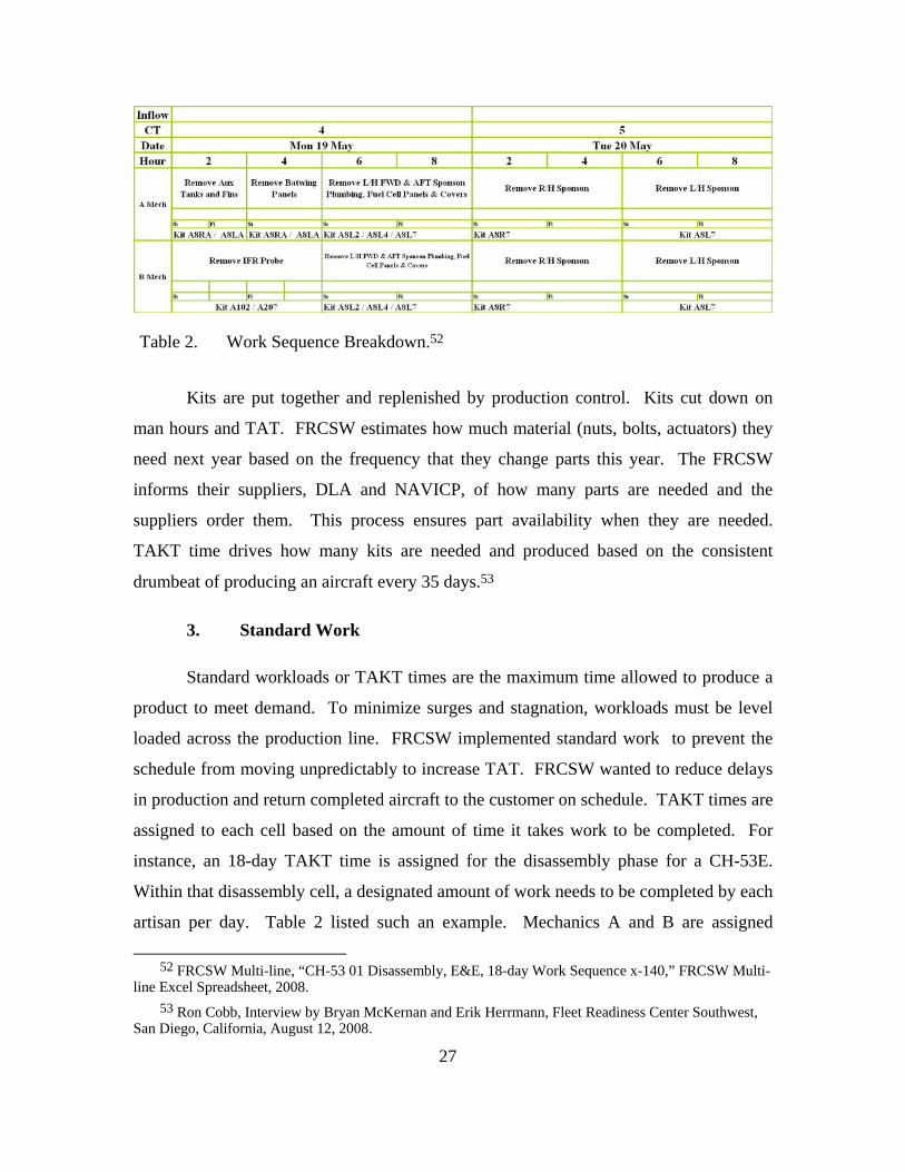
hardware is present. Table 2 lists an example. Kit A8RA is required to remove the
auxiliary tanks and fins. If an artisan completes work early, it is then possible to request
the next kit for the next job within the cell.51
50 Ron Cobb, Interview by Bryan McKernan and Erik Herrmann, Fleet Readiness Center Southwest,
San Diego, California, August 12, 2008. 51 Ibid.
27
Table 2. Work Sequence Breakdown.52
Kits are put together and replenished by production control. Kits cut down on
man hours and TAT. FRCSW estimates how much material (nuts, bolts, actuators) they
need next year based on the frequency that they change parts this year. The FRCSW
informs their suppliers, DLA and NAVICP, of how many parts are needed and the
suppliers order them. This process ensures part availability when they are needed.
TAKT time drives how many kits are needed and produced based on the consistent
drumbeat of producing an aircraft every 35 days.53
3. Standard Work
Standard workloads or TAKT times are the maximum time allowed to produce a
product to meet demand. To minimize surges and stagnation, workloads must be level
loaded across the production line. FRCSW implemented standard work to prevent the
schedule from moving unpredictably to increase TAT. FRCSW wanted to reduce delays
in production and return completed aircraft to the customer on schedule. TAKT times are
assigned to each cell based on the amount of time it takes work to be completed. For
instance, an 18-day TAKT time is assigned for the disassembly phase for a CH-53E.
Within that disassembly cell, a designated amount of work needs to be completed by each
artisan per day. Table 2 listed such an example. Mechanics A and B are assigned
52 FRCSW Multi-line, “CH-53 01 Disassembly, E&E, 18-day Work Sequence x-140,” FRCSW Multi-
line Excel Spreadsheet, 2008. 53 Ron Cobb, Interview by Bryan McKernan and Erik Herrmann, Fleet Readiness Center Southwest,
San Diego, California, August 12, 2008.

28
specific tasks each day throughout the entire phase. TAKT time drives the rate of effort.
If the job requires more resources to be completed on time, then more resources should
be directed toward that cell. This prevents schedule slippage.54
Currently, the United States Marine Corps (USMC) requires FRCSW to complete
12 PMI events per year on the 152 CH-53E in inventory. To maintain a constant
schedule throughout the year, the Multi-line division negotiated that if the fleet could
induct an aircraft every 35 days, then FRCSW could deliver a completed aircraft every 35
days. This TAT equates to 175-180 days to complete one aircraft PMI. Once Multi-line
was able to shape their TAKT times, they were able to stay on schedule.55
4. Cell Development
Cell-based maintenance breaks up the production line into cells, which requires a
certain amount of work to be completed each day. The airplanes move forward within a
cell freeing up the cell for the next airplane. Airplanes move from one cell to another in a
specified number of days that enables the production line to act as a fixed schedule.56
C. MULTI-LINE CELL DEVELOPMENT
To achieve a goal of a 180-day turnaround, FRCSW needed to identify the
number of days an aircraft spends in each maintenance cell. By understanding what is
necessary in each cell and eliminating the non-value added activities, FRCSW further
refined the processes, thus reducing the TAKT time within each cell. The CH-53E line
developed five working cells: Induction, Disassembly, Structures, Assembly, and Final
Assembly. The PMI event incorporates work that needs to be accomplished in all five
cells.57 Table 4 in the Appendix shows a full PMI event schedule.
54 Dave Kelly, Interview by Bryan McKernan and Erik Herrmann, Fleet Readiness Center Southwest,
San Diego, California, August 11, 2008. 55 Ibid. 56 Ibid. 57 Ron Cobb, Interview by Bryan McKernan and Erik Herrmann, Fleet Readiness Center Southwest,
San Diego, California, August 12, 2008.

29
1. Working Cell # 1 - Induction
Induction is the first cell through which an aircraft enters. An aircraft spends
three days in induction where all the administrative work is conducted, for example,
signing over the aircraft discrepancy book (ADB). The 180-day clock starts on the
scheduled induction date. If an aircraft is late for induction, then the 175-180 day TAT
could be extended from the originally scheduled date. Previously, late inductions drove
the TAT to 210 days from the scheduled induction date. The multi-line division’s newly
gained efficiencies are still able to achieve a 170-180 day TAT despite late inductions.58
2. Working Cell # 2 - Disassembly
Disassembly is the next cell. An aircraft spends 15 days in this cell. Artisans
disassemble the aircraft and send the structural parts of the aircraft to plastic media blast
(PMB). PMB is part of the disassembly cell. PMB sprays plastic pellets against the
aircraft to remove paint and corrosion. Since no hazardous waste was created, PMB is a
more environmentally friendly technique than using standard primers or paint thinners.
All of the loose gear that comes off the airplane then goes to the Examination and
Evaluation (E&E) department. E&E x-rays the parts to detect cracks, fatigue, or failures
in the component and upon receiving the results, determines the amount of rework that
needs to be completed. Once E&E is complete with the loose gear, it returns to PMB.
Table 2 shows an example of a standard day within the disassembly cell.59
3. Working Cell # 3 - Structures
An aircraft spends 18 days in the structures cell. Once the structural parts come
back from PMB, they go to E&E. E&E determines the amount of rework necessary. The
18 TAKT time could be more or less depending upon the E&E findings. E&E produces
an evaluation message stating how many days the structures rework requires. Most non-
Operation Iraqi Freedom (OIF) CH-53E’s enter the FRC PMI event needing
58 Ron Cobb, Interview by Bryan McKernan and Erik Herrmann, Fleet Readiness Center Southwest,
San Diego, California, August 12, 2008. 59 Ibid.

30
approximately 12,000 hours of standard work. Those planes are estimated to have a TAT
of 150-160 days. Aircraft returning from OIF come in needing 15,000 hours for a full
PMI event, which means that the amount of effort directed at OIF aircraft is significantly
greater than a non-OIF aircraft. OIF aircraft fly in a more corrosive environment, which
degrades the airframe, rotors and engines. This degradation equates to more effort the
FRC spends on that particular airframe. The majority of the effort spent on the OIF
aircraft occurs typically in the metal shop. Cracks and corrosion drive up the cost of the
OIF aircraft. Some examples of structural reworks are as follows.
• Flight control rod replacement/repair
• Airframe structural support, patching and repair
• Cleaning of internal and external airframe components, for example, removing sand from every crevice of the aircraft
Table 5 in the Appendix shows an eight-day Structures E&E cycle.
4. Working Cell # 4 - Assembly
The assembly cell is the next phase. The assembly cell takes 18 days, of which,
seven days is spent in interior paint. While the aircraft is in interior paint, the mechanics
start building up the sponsons and the tail pylon. Once the aircraft comes back from
interior paint, the mechanics have 10 days to rebuild the aircraft. Since the sponsons and
tail pylon are already completed, they may also be installed on the airframe.
5. Working Cell # 5 - Final Assembly
Final Assembly is the last cell, which takes 18 days. The first 11 days are spent
putting finishing touches on the aircraft. The last seven days are spent in final paint
where the entire exterior of the aircraft is painted. Once the aircraft is painted, it then
goes to weight and balance and then on to the test line.
The test line is where maintenance pilots fly the aircraft to ensure that it performs
to the specifications set forth in the Naval Aviation and Training Operations (NATOPS)
Manual. Functional Check Flights (FCF) are conducted daily, testing various parts of the
airframe for airworthiness. Some procedures conducted on an FCF flight are as follows.

31
• Engine set up
• Rotor alignment
• Autorotation
• Running landings
• Torque checks
• Rotor RPM checks
Prior to the integration of AIRSpeed into the multi-line, an aircraft spent 35 days
on the test line. Since incorporating the 18-day TAKT time in each of the maintenance
cells, the average aircraft now spends only 23 days on the test line. This equates to faster
delivery of the finished product to the customer.60
D. BENEFITS OF AIRSPEED
The AIRSpeed process implemented by the multi-line three years ago has taken
their 380-day TAT and reduced it to 157 days. Figure 4 shows Aircraft X118 through
Aircraft X136 finishing in less than the planned time. This demonstrates the success
AIRSpeed has had on FRCSW Multi-line. AIRSpeed creates predictability. Since the
schedule is no longer variable than the rate of effort must be. AIRSpeed increases the
rate of effort in order to meet the schedule. TAT was further reduced because FRCSW fit
work packages into the amount of days that were available for each event. This increased
the rate of effort dedicated toward a particular job. Essentially, FRCSW are working
more products through the plant. In the past, FRCSW may have only had 10 mechanics,
but under AIRSpeed, FRCSW may require 15. This addition of workers has decreased
overtime. Paying 10 mechanics overtime actually became more expensive than 15
mechanics working a regular shift.
FRCSW has achieved impressive results due to point-of-use tooling, point of use
publications, pre-expendable bins (PEB), kits, standard workload, and cell development.
Figure 5 and 6 demonstrate the time gained from adopting lean techniques.
60 Ron Cobb, Interview by Bryan McKernan and Erik Herrmann, Fleet Readiness Center Southwest,
San Diego, California, August 12, 2008.

32
Time Away From Cell Before Lean Event
At Cell TimeBefore LeanEvent
Away FromCell BeforeLean Event
Figure 5. Artisan Time Off Aircraft is Waste.61
Time Away From Cell After Lean Event
At Cell AfterLean Event
Away FromCell AfterLean Event
Figure 6. Reduced Off Aircraft Time After Lean.62
• 84.7 percent reduction in artisan walking distance for PEB
• 82.5 percent reduction in artisan walking distance for HAZMAT/Commodities
• 93.6 percent reduction in artisan walking distance for SE/IMRL Gear
• 84.2 percent reduction in artisan walking distance for Tooling
• 60.2 percent reduction in artisan walking distance for Technical Publications63
Industry competitors have even recognized the efficiencies that the FRC’s have
gained through AIRSpeed initiatives. An example of this is a contract that the program
manager for the Navy H-60 program has with Raytheon. Raytheon makes the Forward
61 Keith Borror, “NADEP NI CH-53E PMI AIRSPEED PROGRESSION,” The Heavy Lift Quarterly,
December 2005, 12-14. 62 Ibid. 63 Ibid.

33
Looking Infrared (FLIR) System for the Navy’s H-60. Raytheon has subcontracted Fleet
Readiness Center Southeast (FRCSE) to complete ninety percent of the touch labor on
the system installation.64
The addition of new and efficient processes at FRCSW Multi-line through
AIRSpeed initiatives has directly resulted in eliminating their customers’ concerns with
regarding timeliness and cost.
64 Paul Grosklags, Interviewed by Bryan McKernan, Naval Air Systems Command, Patuxent River,
Maryland, September 30, 2008.

34
THIS PAGE INTENTIONALLY LEFT BLANK

35
V. PROGRAM MANAGEMENT AIR VIEWPOINT
A. PROGRAM MANAGEMENT AIR (PMA)
NAVAIR is a United States Navy command, headquartered in Patuxent River,
MD with military and civilian personnel stationed at eight principal continental United
States sites and one site overseas.65 NAVAIR is designed to provide unique engineering,
development, testing, evaluation, in-service support, and program management
capabilities to deliver airborne weapons systems that are technologically advanced and
readily available. Using a full-spectrum approach, the command attempts to deliver
optimal capability and reliability for the Sailor and the Marine.66 NAVAIR’s
organizational structure is divided into six Program Executive Offices (PEO).
• PEO (A) Air ASW, Assault, & Special Mission Programs
• PEO (T) Tactical Aircraft Programs
• PEO (U&W) Unmanned Aviation & Strike Weapons
• PEO (JSF) Joint Strike Fighter
• AIR-1.0
• AIR-5.067
Located within the six PEOs are aviation programs run by PMAs.
1. Program Managers Responsibilities
PMAs are responsible for full life cycle support for an aircraft from design to
retirement.68 PMAs have the responsibility of how money under their control is spent
within their program. PMAs decide on what upgrades and overhauls will be done on the
aircraft and who will do the work. The PMAs are responsible for submitting a budget for
65 Naval Air Systems Command (NAVAIR), “NAVAIR Organization,” Naval Air Systems Command,
http://www.navair.navy.mil (accessed October 8, 2008). 66 Ibid. 67 Ibid. 68 Paul Grosklags, Interviewed by Bryan McKernan, Naval Air Systems Command, Patuxent River,
Maryland, September 30, 2008.

36
their program, which becomes incorporated into the Program Objective Memorandum
(POM). Funds requested within the POM are divided into specific line numbers. For
instance, aircraft procurement -3 (APN-3) is used for purchasing aircraft. Many PMAs do
not deal with APN-3 money because they are no longer procuring aircraft for their
type/Model/series (TMS). PMAs may only be dealing with the operation and
maintenance costs associated with the life cycle of the airframe. Overhauls and
modifications generally fall into this category. Overhauls are conducted at the FRC as
discussed previously. The money for modifications is delineated into two line numbers,
APN-5 and APN-5I. APN-5 money is used to purchase modification kits and APN-5I
money is used to pay for the installation of kits.69
2. Modification Plan
PMAs create a modification plan to retrofit all of their TMS aircraft. As an
example, PMAs will buy kits with APN-5 dollars in 2008 and have them installed with
APN-5I dollars in 2009. The number of kits purchased this year will equate to how many
installs there will be the next year. However, many kits purchased the next year will
equate to how many installs there are the year after that.70 The modification plan drives
the process of upgrading aircraft with newer systems. Each PMA has to discern the
amount of installation dollars needed to have available for a particular modification, as
well as, how to get it done efficiently.
3. PMA Constraints
One of the biggest constraints that PMAs face is when the dollar amount for the
number of kits budgeted for one year does not equal the amount appropriated to install
the kits in the subsequent year. For example, assume PMA budgets in 2008 for 24 kits to
be installed in 2009, at a cost of $100 per hour. Assuming each kit requires 1,000 hours
to be installed, $2.4 million are necessary to fund the installation in 2009. If the
69 Section 1 is drawn directly from Henry Hess, Interviewed by Bryan McKernan, Naval Air Systems
Command, Patuxent River, Maryland, September 30, 2008. 70 Dave Kelly, Interview by Bryan McKernan and Erik Herrmann, Fleet Readiness Center Southwest,
San Diego, California, August 11, 2008.

37
estimated cost of installation increases to $120 per hour, the PMA may only be able to
afford to install 20 kits vice the original 24. Labor rates can change from year to year
making it difficult to match APN-5 dollars with APN-5I dollars. It is also vital that
PMAs get accurate estimates on the number of hours that a modification is going to
require to budget appropriately.
4. Supplemental and Global War on Terrorism Money
After the attacks on September 11, 2001, President Bush requested a $20 billion
package to fight the Global War on Terror (GWOT). Congress authorized $40 billion.71
In addition to annual supplemental authorizations to finance the wars, many programs
within DoD have been able to use GWOT money to finance projects that were not part of
the POM.72 PMAs at NAVAIR have had the ability to execute a number of
modifications on their TMS aircraft using GWOT and supplemental dollars. If a
particular modification could be linked to the GWOT or justified using supplemental
money, than that modification would be funded and executed.73 The supplemental
authorization is being increasingly relied upon to fund recurring costs, which is not its
original intent.
B. MODIFICATION PROCESS
As new technologies are developed, the need to incorporate them within existing
systems increases. These modifications allow existing systems the ability to maintain
leading edge capabilities without the need for replacing the entire system. The CH-53E
has been in operation since 1981 and has undergone multiple upgrades from the original
design.74
71 L.R. Jones and J.L. McCaffery, Budgeting, Financial Management and Acquisition Reform in the
U.S. Department of Defense (Charlotte: Information Age Publishing Inc., 2008), 292. 72 Ibid. 73 Henry Hess, Interviewed by Bryan McKernan, Naval Air Systems Command, Patuxent River,
Maryland, September 30, 2008. 74 Wikipedia, “Ch-53E Super Stallion,” http://en.wikipedia.org/wiki/CH-53E_Super_Stallion
(accessed September 30, 2008).

38
1. Modification Kits
Once a modification is determined necessary to be introduced to the CH-53E,
PMA-261 decides how many aircraft are going to get the modification. If PMA-261
decides to modify all of the airframes (152), then the piece parts are purchased from the
Original Equipment Manufacturer (OEM), such as Bell. The money used to purchase
kits originates from APN-5 appropriations and is usually entered into the POM in the
year prior to execution. After the piece parts required to support the 152 CH-53E aircraft
are received and inventoried, they are then sent to a kitting facility in Orange Park, FL.
The OEM piece parts are then put into kits, and after a technical directive is issued, the
kits are pushed into the field so that the aircraft can be modified.75
2. Completion of Modification Installations
After the kits are built and sent to the fleet, PMA-261 must determine who will
perform the installation. A variety of contractors or the FRC may be used to perform the
installations. Currently, PMA-261 uses contractors such as L3, BF Goodrich, as well as
the FRCs for all CH-53E modifications. L3 is the primary contractor due to their low
cost and their workers’ familiarity with the airframe.76
3. Decision on Installer
The decision to determine who will be performing modification installations is a
difficult one, which takes into account cost, schedule, and location of the work to be
done. The best value to the customer (Program Office and the fleet) is the main concern
when making the contract decision.77 Once an initial determination is made of who will
perform the work, PMA-261 will launch a Rough Order of Magnitude (ROM) to a
75 Henry Hess, Interviewed by Bryan McKernan, Naval Air Systems Command, Patuxent River,
Maryland, September 30, 2008. 76 Ibid. 77 Paul Grosklags, Interviewed by Bryan McKernan, Naval Air Systems Command, Patuxent River,
Maryland, September 30, 2008.

39
particular contractor or FRC to see how many hours it will take to complete a particular
modification. The contractor or FRC will reply with an estimate, and if the PMA finds it
acceptable, the PMA will contract the FRC or contractor.
Examining the contract with L3 as compared to FRCSW or FRCE, the differences
in cost, schedule, and location were identified.78 Labor rates, schedule, and location are
the primary factors that guide the PMA in the decision process.
a. Labor Rates
The labor rate for L3 contractors is $52.00/hour for work completed in the
field.79 The FRCSW Multi-line labor rate is $84.38 and the FRCE labor rate is $94.52
for modification work.80 L3 is cheaper than FRCSW and FRCE ($32.38 and $42.52,
respectively), due in large part to not having any overhead costs associated with
conducting modifications.81 L3 is able to perform the required modification at the flight
line or hangar at $52/hr because the fleet is responsible for paying the overhead. In
contrast, the $84.38 FRCSW rate and $94.52 FRCE rate assumes the modification is
performed at the FRC facilities in conjunction with a PMI event.
b. Schedule
Timing is crucial to the installation of modifications and becomes a major
function in the decision-making process. Marine Corps CH-53E squadrons typically
detach airplanes out to units, such as an Aviation Combat Element (ACE), which is part
of a Marine Expeditionary Unit (MEU), or they may send a four-plane detachment to
various locations around the world, such as the Horn of Africa. Non-deployed CH-53E
squadrons operate with a minimal amount of aircraft. The PMA’s goal is to maximize
78 Henry Hess, Interviewed by Bryan McKernan, Naval Air Systems Command, Patuxent River,
Maryland, September 30, 2008. 79 Cameron Isaac, Interviewed by Bryan McKernan, Naval Air Systems Command, Patuxent River,
Maryland, September 30, 2008. 80 Ron Cobb, Interview by Bryan McKernan and Erik Herrmann, Fleet Readiness Center Southwest,
San Diego, California, 12 August 2008. 81 Ibid.

40
the amount of time the fleet has the aircraft in a reporting status. Between PMI events,
the service life of the CH-53E is 54 months. At the end of 54 months, the aircraft go out
of a reporting status and are sent to its respective FRC for a PMI event. If modifications
between PMI events are needed, the modifications reduce the amount of training time
usable within the service life because of the downtime required for the installation.
Reducing the number of aircraft available for training puts an increased strain on the
squadron and remaining aircraft. A balance is found in modifying aircraft and using
them for operational commitments. Priority for modification work goes to aircraft that
are part of a MEU or are deploying to a wartime theater. Aircraft currently deployed may
receive their modifications once they return home.82
c. Location of Work
The location of the installation work is important in the decision-making
process because moving an aircraft to and from a production location adds to the time it
takes to complete the installation. If the aircraft has to be moved, it potentially adds one
day for transport and one day for preparation before work can begin. This would occur if
an aircraft was moved from the squadron to the FRC for modification work. If
installations can be done on-site then an aircraft can be readied one day and worked on by
contractors the next day.
C. SUMMARY
This chapter described the process of how modifications are budgeted, built, and
installed. Through interviews, the variables affecting the PMA’s decisions were
determined with regard to modifications including the needs of the fleet, labor rates,
schedule, constraints, and location of work. All of these factors must be considered when
determining best value to the customer.
82 Section b is a summary drawn directly from Henry Hess, Interviewed by Bryan McKernan, Naval
Air Systems Command, Patuxent River, Maryland, September 30, 2008.

41
VI. COMPARISON OF CONTRACTOR VS. FRCSW
A. FACTORS AFFECTING CHOICE OF PROVIDER
There are multiple factors to be considered when choosing among FRCs and
civilian contractors. The decision must balance the cost and timing of work including
where the work is accomplished. Additionally, perceptions regarding the provision of
service by either FRCSW or contractors are relevant.
1. Labor Rates
Cost is the leading factor in the decision to use contractors for modification
installations. The civilian contractor holds the advantage because a contractor may be
able to quote a lower price. In the case of L3, approximately a $52/hour labor rate is set
because they have few overhead costs related to the installations. This is a direct result of
being able to conduct the modification work at the hangar where the aircraft are kept. 83
FRCs have higher overhead costs associated with their labor rates. FRCSW is
approximately $84/hour and FRCE is approximately $94/hour. This results from having
to do the work done at the FRC’s location vice the aircraft’s location.84
2. Schedule
The time in which the work is completed is important because the need for
modification installations can vary from year to year. Civilian contractors hold an
advantage in that they can go to the squadron when a modification is necessary. They
also have the benefit of having skilled labor only performing modification work vice
other maintenance work. This allows them to focus solely on improving their efficiency
83 Henry Hess, Interviewed by Bryan McKernan, Naval Air Systems Command, Patuxent River,
Maryland, September 30, 2008. 84 Cameron Isaac, Interviewed by Bryan McKernan Naval Air Systems Command, Patuxent River,
Maryland, September 30, 2008.

42
in installing modifications. For example, L3 initially installed the Blue Force Tracker
upgrade in two weeks. As L3 became more proficient with the installation, L3 reduced
the installation time to seven days.85
Another advantage the contractor has over the FRC is that the contractor can
potentially perform the modification on more than 24 aircraft per year. Each FRC is
limited in that it can only do PMI events on 12 aircraft per year whereas the contractor is
not limited. If a modification installation is included in the PMI event then this results in
only 24 aircraft being available for upgrade in any given calendar year.
One advantage in using the FRC for installations is that the modification can be
done concurrently with a PMI event. During the PMI event, the aircraft is out of service
and may require 12,000 hours of work. If a modification is incorporated with this event,
it may increase the hour’s requirement to 14,000 hours. FRCSW’s AIRSpeed initiatives
have allowed the PMI event, no matter the hour’s requirement, to be completed on
schedule.86 This means that an aircraft could be completed with all of the necessary
upgrades in less than 180 days by increasing the resources used to complete the job. The
aircraft comes out of the FRC and back to the fleet ready for operations. The aircraft
does not need to be taken out of service for the modification once it is returned to the
squadron.
3. Location of Work
The location of the modification installation affects both cost and schedule. By
having the modification installation occur at an FRC, increased time is incurred to
account for transporting the aircraft to and from the FRC. Additionally, since FRC’s
have a higher overhead rate than contractors who perform modification installations at
the flight line, a higher labor rate will be paid to perform the installation at the FRC. The
contractor has the advantage in that it is possible to use maintenance personnel from the
85 Section 2 is a summary drawn directly from Henry Hess. Interviewed by Bryan McKernan, Naval
Air Systems Command, Patuxent River, Maryland, September 30, 2008. 86 Dave Kelly, Interview by Bryan McKernan and Erik Herrmann, Fleet Readiness Center Southwest,
San Diego, California, August 11, 2008.

43
squadron to ready the aircraft for modification work the day prior to contractor work
beginning. The contractor can then complete the modification installation on the flight
line and give the aircraft back to the customer in the same day. This process is repeated
as the contractor moves from one aircraft to the next on the flight line.
4. Perceptions
Decision makers perceptions of different organizations affect how decisions are
made.87 On the one hand, the civilian contractors, particularly L3, are seen as
particularly efficient and effective at PMA-261. Their ability to perform aircraft
modifications in a timely and cost effective manner has helped them to be the preferred
source for future aircraft modifications. On the other hand, Naval Aviation Depots
(NADEPs) have been criticized for their inability to complete projects in a timely
manner. The quality was never in question, but schedule slippage and cost overrun were
seen as the norm.88 When NADEPs became FRCs during the restructuring in 2005, those
individuals who had experienced the problems with NADEPs, continued to have
concerns.89 The FRCSW Multi-line division contributed to these concerns, prior to
AIRSpeed, by having an average completion time of greater than 300 days. Currently,
FRCSW is completing aircraft in as little as 154 days.90
The use of contractors to execute modifications contributes to the concerns
regarding the FRCs. Aircraft immediately going into a modification installation phase by
L3 on the flight line after returning from the FRC reinforces the poor impression of
FRCs. Some in the fleet may see it as the FRC not being competent enough to perform a
modification installation. They individuals may not understand that it is less expensive to
87 Stephan P. Robbins, Organization Behavior: Perception and Individual Decision Making (Pearson
Education Prentice Hall, 2008). 88 Henry Hess, Interviewed by Bryan McKernan, Naval Air Systems Command, Patuxent River,
Maryland, September 30, 2008. 89 Paul Grosklags, Interviewed by Bryan McKernan, Naval Air Systems Command, Patuxent River,
Maryland, September 30, 2008. 90 Dave Kelly, Interview by Bryan McKernan and Erik Herrmann, Fleet Readiness Center Southwest,
San Diego, California, August 11, 2008.

44
use the contractor to perform the upgrade. They only see the aircraft as unavailable for a
longer period of time because the modification was not completed while the FRC was
performing a PMI.91
Some individuals have also been told that the addition of modification work to a
PMI event will cause the schedule to be delayed and the FRC will not be able to deliver
the finished product on time.92 The author’s research shows that given the AIRSpeed
initiatives performed at FRCSW, this belief is unfounded. By providing more resources
for aircraft, the FRC can achieve the desired results without impacting the schedule.93
Costs will be higher because the rate FRC charges is higher, but no additional work will
be required when the aircraft is returned to the fleet.
An additional advantage to using the FRC for modification work is that they can
become proficient on the latest upgrades to the aircraft and stay competitive with
industry. Since the FRC is performing work on each CH-53E on or about every 54
months, FRCs need to know what new systems are being added to the aircraft and how
those systems operate. This would help FRC to keep their completion time low because
FRC artisans would already understand the new systems when a PMI event is scheduled.
91 Dave Kelly, Interview by Bryan McKernan and Erik Herrmann, Fleet Readiness Center Southwest,
San Diego, California, August 11, 2008. 92 Henry Hess, Interviewed by Bryan McKernan, Naval Air Systems Command, Patuxent River,
Maryland, September 30, 2008. 93 Dave Kelly, Interview by Bryan McKernan and Erik Herrmann, Fleet Readiness Center Southwest,
San Diego, California, August 11, 2008.

45
Civilian Contractor Fleet Readiness Center COST Advantage: $52/hour (no overhead) Disadvantage: $84-$94/hour Advantage: Can do unlimited
number of aircraft per year Disadvantage: Can only work 24 aircraft per year
TIME Advantage: They come to you Disadvantage: Work done at FRC
Advantage: Artisans working solely on modification
Disadvantage: Artisans responsible for entire aircraft
Disadvantage: Only modification work is being done.
Advantage: modification can be done concurrently with PMI
Disadvantage: Time aircraft spends out of service increased
Advantage: No additional out of service time when done with PMI event.
LOCATION OF WORK
Advantage: Can return modified aircraft to customer and begin work on next aircraft in same day.
Disadvantage: must complete entire PMI before returning aircraft to customer.
Advantage: Can use labor of maintenance personnel to prep aircraft / less overhead for contractor.
Disadvantage: higher rate due to higher overhead costs.
PERCEPTION Advantage: Confidence level high with respect to performance
Disadvantage: Confidence level still low due to poor performance before AIRSpeed
Advantage: Confidence level high with respect to timeliness of modification
Disadvantage: Belief that modification work will increase schedule
Disadvantage: Fleet concern because aircraft are out of service for PMI and separate modification work
Advantage: Keeping work inside DoD keeps FRC up to date with new technologies
Table 3. Comparison of Contractor vs. FRC

46
THIS PAGE INTENTIONALLY LEFT BLANK

47
VII. CONCLUSIONS AND RECOMMENDATIONS
A. INTRODUCTION
The primary purpose of this project is to answer the question why are the FRCs
not getting more CH-53E modification work when they have the capacity/capability to
complete the work? This study also determines who is best suited and what the best
process is to complete modification work on the CH-53 aircraft. FRCSW was the
primary FRC studied along with labor rates from FRCE. PMA-261, APML, for the CH-
53 program, was interviewed along with the Commander of all six FRCs. Cost, timing,
location of work, and perception were the critical areas revealed from the author’s
research affecting the answer to the primary research question. Participants in the
process have different views of how to best serve the customer. The purpose is to present
recommendations on how to serve the customer best from an independent third party’s
viewpoint based on the analysis of the data gathered for this project.
Modifications occur at varying times during the year. As previously noted, the
program office budgets for modifications annually. By analyzing costs and time
schedules, PMA-261 determines the best value for the customer and then decides how
best to begin modifying the aircraft. Ideally, the best time to modify an aircraft is when
the fleet cannot use it for operations. This time period comes every 54 months when the
aircraft is at an FRC for a PMI event. By modifying aircraft during the PMI event, the
aircraft would come back to the fleet with the PMI and all necessary modifications
completed. The modification could be conducted concurrently with the PMI event and
while still meeting the 180-day TAT. This method eliminates the additional down time
of the aircraft because an aircraft would not have to come out of a 180-day PMI at the
FRC and then immediately enter into a modification phase on the flight line. One FRC
per coast maintains the CH-53E aircraft. Both FRCs are capable of performing 12 PMI
events per year for the CH-53 community. This means in any given year only 24 aircraft
are available to receive the modification concurrent with a PMI event.

48
When using a contractor to complete the modification installation, such as L3, the
squadron personnel ready the aircraft and then contractors come in and perform the
modification work. The down time of the aircraft is the amount of time it takes the
contractors to install the modification. The aircraft is then returned to the squadron days
or weeks later with the new modification incorporated. This method may be preferred
when the aircraft is not due for a PMI event, the modification is required immediately,
and/or the contracted company can perform the work less expensively than the FRC.
B. PRIMARY QUESTION
1. Is It in the Best Interest of the United States Marine Corps to Utilize Fleet Readiness Centers to Conduct More CH-53E Modification Work?
Based on the data, FRCSW has achieved capacity/capability to complete
modification work through AIRSpeed. The cost data, however, does not justify using
FRCs to complete modification work when L3 is less expensive. Cost is a constraint in
any program. However, if an aircraft is already out of service, then that would be the best
time to install any new modifications available. From the author’s perspective, as
aviators, the money saved by using contractors does not make up for the time lost to the
fleet.
C. SECONDARY QUESTION
1. Can the FRCs Conduct Modifications in Conjunction with a PMI Event in the 180-day TAT?
The results from the interviews conducted indicate that individuals who have
previous experience with FRCs do not have confidence in the FRC’s ability to produce
aircraft in a timely manner. The idea of contracting FRCs to do simple or complex
modifications is said to be more expensive and more time consuming. The cost issue
cannot be disputed; the FRCs are more expensive. Time can be a factor in the PMA’s
review. Since 2005, FRCSW has reduced their TAT from 380 days to 180 days with the
last few aircraft coming in at less than 160 days. Adoption of AIRSpeed is the driving

49
factor in this accelerated TAT. Under AIRSpeed, time is not a factor; the rate of effort is.
If more work needs to be done to complete a job on time then the rate of effort is
increased. This was a key finding discovered in the research. The cost to conduct the
modification at an FRC may be $30-$40 more expensive than using L3, but there is no
additional time lost. Time lost to the fleet can have more of an impact than cost.
D. RECOMMENDATIONS
1. PMA’s Need to Reexamine the FRC’s Capabilities
The FRCs have come a long way in the past three years. It is evident from the
research conducted that they are competitive with industry and industry is starting to
recognize their abilities as mentioned in the Raytheon/FRCSE example. Benefits to
keeping the work in house is that finished products are produced in a timelier manner and
the knowledge base is reinforced within the DoD.
2. PMA-261 Should Have FRCSW and FRCE Install All Available Modifications in Conjunction with the 24 Annually Scheduled PMI Events
The fleet will be better served if all available modifications are conducted in
conjunction with the scheduled PMI events. Since only 24 aircraft can be completed by
FRC’s in a given year, contractors should be utilized for the aircraft not undergoing a
PMI.
E. FURTHER ANALYSIS QUESTIONS
1. What is the Cost to the Fleet to Have an Aircraft Out of Service for One Day?
The cost of an aircraft lost to modification work is difficult to quantify. Numbers
of available aircraft are factored into training plans and arguably, more aircraft means

50
more training. Costs of maintenance, personnel, available flight hours, and readiness are
all factors that need to be calculated to determine the total cost to the fleet. The
calculation of the aforementioned factors is beyond the scope of this study.

51
APPENDIX.
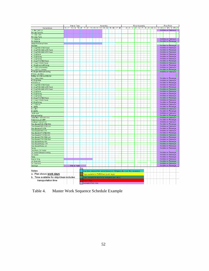
52
Table 4. Master Work Sequence Schedule Example

53
Table 5. Structures Examination & Evaluation 8-Day Sequence Example

54

55
Table 6. Assembly 18-Day Sequence Example

56
Table 7. Final Assembly 18-Day Sequence Example

57

58

59
Table 8. Test Line 18-Day Sequence Example

60
THIS PAGE INTENTIONALLY LEFT BLANK

61
LIST OF REFERENCES
Antony, J. “Pros and Cons of Six Sigma: An Academic Perspective.” Onesixsigma.com, http://onesixsigma.com/node/7630 (accessed September 8, 2008).
“Base Closure and Realignment Report Part 1 of 2: Results and Process. Volume 1.” Department of Defense. Washington, D.C., 2005.
Best Manufacturing Practices. “Naval Aviation (NAVAIR) Depot, North Island – San Diego, CA: Best Practices.” http://www/bmpcoe.org/bestpractices/internal/nadep/index.html (accessed November 20, 2007).
Borror, Keith. “NADEP NI CH-53E PMI AIRSPEED PROGRESSION.” The Heavy Lift Quarterly, December 2005.
Clemmons, F. R. and Falconieri, H. M. “Analysis of Fleet Readiness Center Southwest Concept Integration. New-Employee Orientation and Communications Process.” MBA Project. Naval Postgraduate School, 2007.
Cobb, Ron. Interview by Bryan McKernan and Erik Herrmann. Fleet Readiness Center Southwest, San Diego, California, August 12, 2008.
Curran, T. and Schimpff, J. J. “An Analysis of Factors Generating the Variance between the Budgeted and Actual Operating Results of the Naval Aviation Depot at North Island, California.” MBA Project. Naval Postgraduate School, June 2008.
Dynamic Research Corporation and Clemson University. “Lean Pathways. Lean Overview for CVN Application.” Navy MANTECH, 2003.
Fleet Readiness Center Southwest. “Homepage.” Fleet Readiness Center Southwest, http://www.frcsw.navy.mil/frcsw (accessed November 30, 2007).
FRCSW Multi-line. “FY08 AIRSpeed Initiatives,” FRCSW PowerPoint 2008.
GAO Report. “Observations on Prior and Current BRAC Rounds.” http://www.gao.gov/new.items/d05614 (accessed 1 November 2008).
Grosklags, Paul. Interviewed by Bryan McKernan. Naval Air Systems Command. Patuxent River, Maryland, September 30, 2008.
Harnden, P. D. “Integrating Lean and Six Sigma and AIRSpeed within the NAVAIR 4.1 Organizational Improvement Efforts.” White Paper. Commonwealth Centers for High Performance Organizations, 2004.

62
Hess, Henry. Interviewed by Bryan McKernan. Naval Air Systems Command. Patuxent River, Maryland, September 30, 2008.
Isaac, Cameron. Interviewed by Bryan McKernan. Naval Air Systems Command, Patuxent River, Maryland, September 30, 2008.
Johns, J. “Naval Aviation Transformation Brief.” Defense Supply Center Richmond. http://www.dscr.dla.mil/uuserweb/dscrl/alc.alc2006/ACL%202006%20Briefings/1%20(A-8.1)%20Services%20Senrio%20Panel%20John%20John.ppt#275.17.Slide17 (accessed December 15, 2007).
Jones, L.R. and McCaffery, J.L. Budgeting, Financial Management and Acquisition Reform in the U.S. Department of Defense. Charlotte: Information Age Publishing Inc., 2008.
Kelly, Dave. Interview by Bryan McKernan and Erik Herrmann. Fleet Readiness Center Southwest, San Diego, California, August 11, 2008.
Montes, J.F. “Organizational Design Analysis of Fleet Readiness Center Southwest Components Department.” Thesis. Naval Postgraduate School, December 2007.
Moore, Joe. “BRAC 2005; The New Integrated I&D Level Maintenance.” http://www.av8.org/brac-05, (accessed 1 November 2008).
Motley, B. “Using Theory of Constraints (TOC) to Improve Quality, Cost and Productivity.” Defense Systems Management College, June 2004.
Motorola University “Six Sigma Dictionary.” Motorola Inc. http://www.motorola.com/content.jsp?globalObjectId=3074-5804 (accessed September 8, 2008).
Naval Aviation Enterprise. “Enterprise AIRSpeed.” http://www.cnaf.navy.mil/airspeed (accessed August 15 2008).
Naval Air Systems Command (NAVAIR). “NAVAIR Organization.” http://www.navair.navy.mil (accessed October 8, 2008).
Naval Air Systems Command. “COMNAVAIRFOR INSTRCUTION 4790.2. (February 1, 2005). Naval Aviation Maintenance Program (NAMP). (Vol. 1).” Naval Air Systems Command, http://logistics.navair.navy.mil/4790/library/VOL_1.pdf (accessed March 11, 2007).
RIMES. “What is a Lean Enterprise?” http://www.rimes.org/programs_le.html (accessed October 1, 2008).

63
Robbins, Stephan P. Organization Behavior: Perception and Individual Decision Making, Pearson Education Prentice Hall, 2008.
Tennant, G. Six Sigma: SPC and TQM in Manufacturing and Services. Gower Publishing, Ltd., 2001.
Wikipedia. “Ch-53E Super Stallion.” http://en.wikipedia.org/wiki/CH-53E_Super_Stallion (accessed September 30, 2008).

64
THIS PAGE INTENTIONALLY LEFT BLANK

65
INITIAL DISTRIBUTION LIST
1. Defense Technical Information Center Ft. Belvoir, Virginia
2. Dudley Knox Library Naval Postgraduate School Monterey, California
3. Marine Corps Representative Naval Postgraduate School Monterey, California
4. Director, Training and Education, MCCDC, Code C46 Quantico, Virginia
5. Director, Marine Corps Research Center MCCDC, Code C40RC Quantico, Virginia
6. Marine Corps Tactical Systems Support Activity Attn: Operations Officer Camp Pendleton, California
7. Ken J. Euske
Naval Postgraduate School Monterey, California
8. Becky Jones Naval Postgraduate School Monterey, California
9. Commanding Officer Fleet Readiness Center Southwest NADEP North Island San Diego, California
10. Dave Kelly
Fleet Readiness Center Southwest NADEP North Island San Diego, California

66
11. Commander Fleet Readiness Centers / Air -6.0 Naval Air Systems Command Patuxent River, Maryland
12. LtCol Henry Hess
Naval Air Systems Command Patuxent River, Maryland