Embed Size (px)
Citation preview

7/27/2019 07core
http://slidepdf.com/reader/full/07core 1/39
CORE -1
Xilinx CORE Generator
7/27/2019 07core
http://slidepdf.com/reader/full/07core 2/39
CORE -2
Overview I
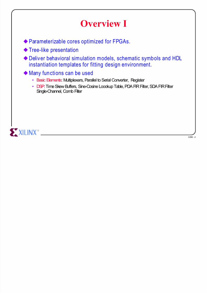
uParameterizable cores optimized for FPGAs.
u Tree-like presentation
uDeliver behavioral simulation models, schematic symbols and HDLinstantiation templates for fitting design environment.
uMany functions can be used• Basic Elements: Multiplexers, Parallel to Serial Converter, Register
• DSP: Time Skew Buffers, Sine-CosineLoookupTable, PDA FIR Filter, SDA FIR Filter Single-Channel, Comb Filter

7/27/2019 07core
http://slidepdf.com/reader/full/07core 3/39
CORE -3
Overview II
• Math: Accumulator, Adders/Subtractors,Complements, Constant Coefficient Multipliers,Parallel Multipliers, Integrator, square Root
• Memories: Delay Element, RegisteredDualPortRAM, Registered ROM, RegisteredSinglePortRAM, Synchronous FIFO

7/27/2019 07core
http://slidepdf.com/reader/full/07core 4/39
CORE -4
How to Obtain New Cores andUpdates
uNew cores can be downloaded from the Xilinx web site and easilyadded to the CORE Generator.
uBookmark
http://www.xilinx.com/products/logicore/coregen
and keep in touch regularly for updates.

7/27/2019 07core
http://slidepdf.com/reader/full/07core 5/39
CORE -5
Project Management
uSetup the Coregen.ini File
uSet the CORE Generator System Options
uSet the CORE Generator Output Options

7/27/2019 07core
http://slidepdf.com/reader/full/07core 6/39
CORE -6
Setup the Coregen.ini File
u coregen.ini File• “coregen.ini” is created during the install of the CORE Generator and can be found in the
following directory:
<CORE_Generator_Install_Path>/coregen/wkg
• Many parameters are set in this file
u The parameters expressed in the coregen.ini file:• The following parameters are determined during installation, andusually do not need to be
changed:
– CoreGenPath, FoundationPath, AcrobatPath, and AcrobatName.
• Other settings will usually need to be changed by the user, such as
– SelectedProducts, ProjectPath, BusFormat, and XilinxFamily.
• Changes to your output options and system options are best done through the COREGenerator Output format andSystem Options forms .
– Options -> Output format for the Output format form
– Options -> System Options… for the System Options form.
7/27/2019 07core
http://slidepdf.com/reader/full/07core 7/39
CORE -7
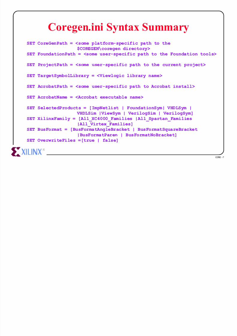
SET CoreGenPath = <some platform-specific path to the$COREGEN\coregen directory>
SET FoundationPath = <some user-specific path to the Foundation tools>
SET ProjectPath = <some user-specific path to the current project>
SET TargetSymbolLibrary = <Viewlogic library name>
SET AcrobatPath = <some user-specific path to Acrobat install>
SET AcrobatName = <Acrobat executable name>
SET SelectedProducts = [ImpNetlist | FoundationSym| VHDLSym | VHDLSim |ViewSym | VerilogSim | VerilogSym]
SET XilinxFamily = [All_XC4000_Families |All_Spartan_Families
|All_Virtex_Families]SET BusFormat = [BusFormatAngleBracket | BusFormatSquareBracket
|BusFormatParen | BusFormatNoBracket]SET OverwriteFiles =[true | false]
Coregen.ini Syntax Summary

7/27/2019 07core
http://slidepdf.com/reader/full/07core 8/39
CORE -8
Sample coregen.ini file
SET FoundationPath = C:\FNDTN\ACTIVE
SET ProjectPath = C:\cg95_cur\coregen\wkg
SET TargetSymbolLibrary = primary
SET XilinxFamily = All_XC4000_Families
SET AcrobatPath = C:\Acrobat3\Reader\
SET AcrobatName = AcroRd32.exe
SET SelectedProducts = ImpNetlist FoundationSym

7/27/2019 07core
http://slidepdf.com/reader/full/07core 9/39
CORE -9
Setup SelectedProducts I
uSelectedProducts - This setting defines the type of output files tobe created each time a module is built .
SET SelectedProducts = ImpNetlist FoundationSym
• ImpNetlist: Implementation Netlist.
– This is the gate level netlist that will be used to implement the logic of the particular
core that the COREGeneratorSystem has created. – In an HDL synthesis design flow, an HDL instantiation of the core references this
netlist as a “black box” in a schematic design flow, a schematic symbol references thisnetlist.
• ViewSym: ViewLogic Schematic Symbol.
– When specified this option will create aViewLogic schematic symbol that can be usedin your ViewLogicschematic capture tools to instantiate the module netlist.
• FoundationSym: Foundation Schematic Symbol.
– When specified this option will create a Foundation schematic symbol that can beused in your Foundation schematic capture tools to instantiate the module netlist.

7/27/2019 07core
http://slidepdf.com/reader/full/07core 10/39
CORE -10
Setup SelectedProducts II
• VHDLSym: VHDL Instantiation Template.
– When specified this option will create a VHDL instantiation template that can be usedin your HDL design capture tools to instantiatethe module netlist.
• VHDLSim: VHDL Behavioral Simulation Model.
– When specified this option will create a VHDL simulation model, which can be used toverify the functional simulation of the module netlist.
• VerilogSym: Verilog Instantiation Template.
– When specified this option will create a Verilog instantiation template that can be usedin your HDL design capture tools to instantiatethe module netlist.
• VerilogSim: Verilog Behavioral Simulation Model.
– When specified this option will create a Verilog simulation model, which can be used toverify the functional simulation of the module netlist.

7/27/2019 07core
http://slidepdf.com/reader/full/07core 11/39
CORE -11
Set the CORE Generator SystemOptions
uOptions -> System Options ...• All default settings are set in “coregen.ini”
uProject Path• This setting defines the project working directory
uViewlogic Library Alias• This setting defines the name of the
ViewLogic library alias.
u Foundation Path• This setting defines the path location of
the Foundation CAE tools
uSave settings upon OK• Make these options permanent

7/27/2019 07core
http://slidepdf.com/reader/full/07core 12/39
CORE -12
Set the CORE Generator OutputOptions I
uOptions -> Output Format...
uEdif Implementation Netlist• A gate level netlist
• Output:<CoreName>.edn
uViewlogic Schematic Symbol• AViewlogicschematic symbol and
a simulation wire file
• Output: wir\<CoreName>.1sym\<CoreName>.1
u Foundation Schematic Symbol
• A Foundation schematic symbol and a simulation file• Output: <CoreName>.alr
lib\project_name.sym

7/27/2019 07core
http://slidepdf.com/reader/full/07core 13/39
CORE -13
Set the CORE Generator OutputOptions II
uVHDL Instantiation Template• A VHDL instantiation template that can be used in your HDL design capture tools to
instantiate the module netlist.
• Output: <CoreName>.vhi
uVHDL Behavioral Simulation Model• A VHDL simulation model which can be used to verify the functional simulation of the
module netlist.
• This file is not intended to be synthesized.
• It is only provided for behavioral simulation
• Output: <CoreName>.vhd
uVerilog Instantiation Template• A Verilog instantiation template that can be used in your HDL design capture tools to
instantiate the module netlist.
• Output: <CoreName>.vei
7/27/2019 07core
http://slidepdf.com/reader/full/07core 14/39
CORE -14
Set the CORE Generator OutputOptions III
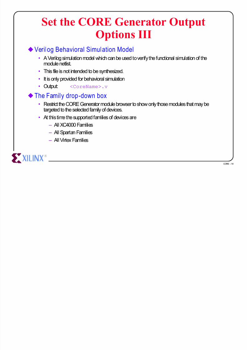
uVerilog Behavioral Simulation Model• A Verilog simulation model which can be used to verify the functional simulation of the
module netlist.
• This file is not intended to be synthesized.
• It is only provided for behavioral simulation
• Output: <CoreName>.v
u The Family drop-down box• Restrict the CORE Generator module browser to show only those modules that may be
targeted to the selected family of devices.
• At this time the supported families of devices are
– All XC4000 Families
– All Spartan Families
– All Virtex Families

7/27/2019 07core
http://slidepdf.com/reader/full/07core 15/39
CORE -15
Using the CORE Generator
uCore Browser Tree
uGetting Module Data Sheets
uParameterizing a Module
uCOE Files

7/27/2019 07core
http://slidepdf.com/reader/full/07core 16/39
CORE -16
Core Browser Tree
u The most common view of the CORE Generator is the CoreBrowser window.
u This window allows you to browse the many cores that areavailable from the CORE Generator installation.
uCores that fall into particular application categories are groupedinto folders to assist you in locating the module appropriate for your needs.
u To expand a folder, double click on the folder icon to the left of thefolder name.

7/27/2019 07core
http://slidepdf.com/reader/full/07core 17/39
CORE -17
Accessing Core Data Sheet
u A data sheet for the selected core can be requested at any time• 1. select the core in the core browser
• 2. click on the SpecSpecbutton on the CORE Generator toolbar.
• This action will launch the Acrobat Reader application and display the core data sheet.

7/27/2019 07core
http://slidepdf.com/reader/full/07core 18/39
CORE -18
Parameterizing a Core I
uMost cores have a parameterization window.
uDouble-clicking on a core’s icon or descriptive text wi ll reveal theparameterization window for that module.
u For example : Registered Loadable Adder

7/27/2019 07core
http://slidepdf.com/reader/full/07core 19/39
CORE -19
• Component Name
– allows you to assign a nameto a module that you create.
– Restrictions:• Up to 8 characters
• No extensions
• Must begin with a alphacharacter: a-z (No Capital letters)
• May include (after the firstcharacter): 0-9, _
• The illegal or invalid field will behighlighted in red until the problemis corrected.
u Assuming there are no problems with any of the parameters thathave been specified, pressing GenerateGenerate wil l cause the COREGenerator to create files of the requested types.
uPressing CancelCancel will return you to the module browser windowwithout generating any files.
Parameterizing a Core II

7/27/2019 07core
http://slidepdf.com/reader/full/07core 20/39
CORE -20
COE Files
uSome cores can require a significant amount of information tocompletely specify their behavior.
uCores of this type will have a button on their parameterizationwindows with which you can load their parameterizationinformation from a file.
u Addi tional information about a part icular Core’s COE file can befound in that Core’s datasheet.
• For examples of PDA FIR, RAM, and ROM COE files, please look in thecoregen/wkgdirectory.

7/27/2019 07core
http://slidepdf.com/reader/full/07core 21/39
CORE -21
Example - PDA FIR Filter
7/27/2019 07core
http://slidepdf.com/reader/full/07core 22/39
CORE -22
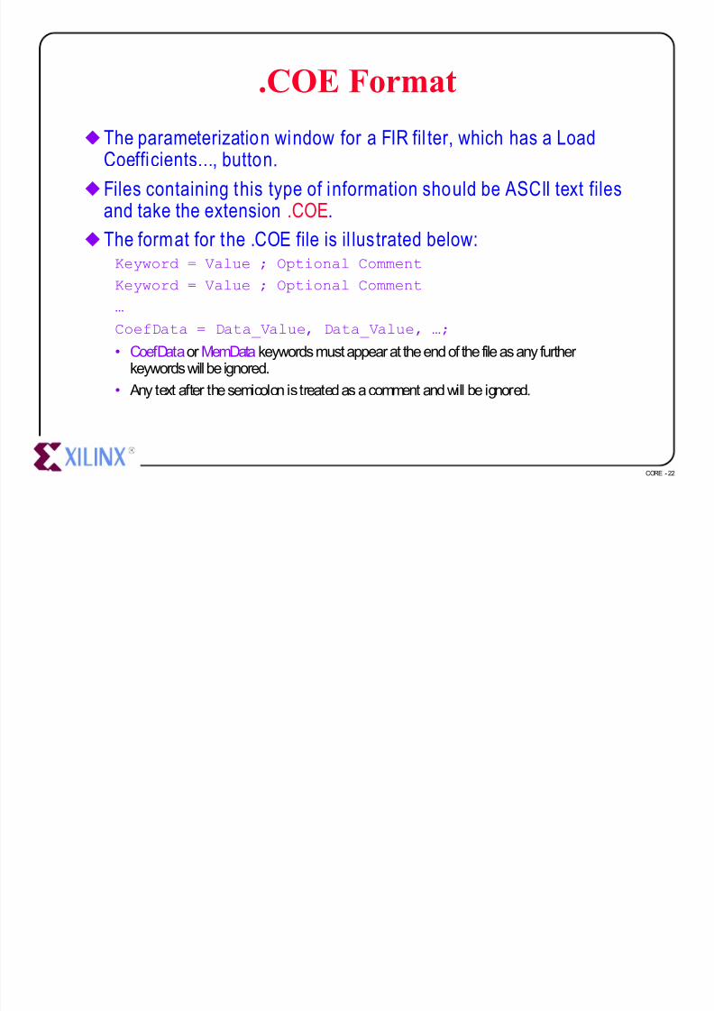
.COE Format
u The parameterization window for a FIR fil ter, which has a LoadCoefficients..., button.
u Files containing this type of information should be ASCII text filesand take the extension .COE.
u The format for the .COE file is il lustrated below:Keyword = Value ; Optional Comment
Keyword = Value ; Optional Comment
…
CoefData = Data_Value, Data_Value, …;
• CoefDataor MemData keywords must appear at the end of the file as any further
keywords will be ignored.• Any text after the semicolon is treated as a comment and will be ignored.

7/27/2019 07core
http://slidepdf.com/reader/full/07core 23/39
CORE -23
.COE Examples - PDA FIR
*********** EXAMPLE: PDA FIR ***********component_name=fltr16; Number_of_taps=16;Input_Width = 8;Signed_Input_Data = true;Output_Width = 15;Coef_Width = 8;Symmetry = true;Radix = 10;Signed_Coefficient = truecoefdata=1,-3,7,9,78,80,127,-128;

7/27/2019 07core
http://slidepdf.com/reader/full/07core 24/39
CORE -24
.COE Examples - SDA FIR
*********** EXAMPLE: SDA FIR ***********component_name = sdafir;number_of_taps = 6;radix = 10;input_Width = 10;output_Width = 24;coef_Width = 11;symmetry = false;coefdata = -1,18,122,418,-40,3;

7/27/2019 07core
http://slidepdf.com/reader/full/07core 25/39
CORE -25
.COE Examples - RAM
*********** EXAMPLE: RAM ***********component_name=ram16x12;
Data_Width = 12; Address_Width = 4;Depth = 16;Radix = 16; memdata=346,EDA,0D6,F91,079,FC8,053,FE2,03C,FF2,02D,FFB,022,002,01A,005;

7/27/2019 07core
http://slidepdf.com/reader/full/07core 26/39
CORE -26
.COE Examples - ROM
*********** EXAMPLE: ROM ***********component_name=rom32x8;Data_Width = 8; Address_Width = 5;
Depth = 32;Radix = 10; memdata=127,127,127,127,127,126,126,126,125,125,125,4,3,2,0,-1,-2,-4,-5,-6,-8,-9,-11,-12,-13,-38,-39,-41,-42,-44,-45,-128;

7/27/2019 07core
http://slidepdf.com/reader/full/07core 27/39
CORE -27
.COE Examples - Virtex Block Ram
*********** EXAMPLE: Virtex Block Ram ***********component_name=blkram;Depth =256;Data_Width =32;Radix =16;Default_Data =FFF; MEMORY_INITIALIZATION_VECTOR =FF0,F0F,0FF,FF4,F4F,4FF,FF8,F8F,8FF;

7/27/2019 07core
http://slidepdf.com/reader/full/07core 28/39
CORE -28
CORE Generator Design Flow
Foundation Schematic Flow
and
Foundation Express Flow

7/27/2019 07core
http://slidepdf.com/reader/full/07core 29/39
CORE -29
Foundation Schematic Flow I
u 1. Set a Foundation Project• Create a new project or Select an existing Schematic project from the Foundation Project
Manager.
u 2. Set the CORE Generator Output Format• From the CORE Generator Options menu, select Output
Format, and check the following options:

7/27/2019 07core
http://slidepdf.com/reader/full/07core 30/39
CORE -30
Foundation Schematic Flow II
u 3. Set the System Options• From the CORE Generator Options menu, select System Options.
• Set the Project Path to point to your Foundation project directory.
– The selected Project Path should be a validFoundation project or an error will occur whengenerating the core.
– This path should point to the directory whereFoundation has been installed.

7/27/2019 07core
http://slidepdf.com/reader/full/07core 31/39
CORE -31
Foundation Schematic Flow III
u 4. Select the module you want to generate by navigating to thedesired module and clicking on it.
• Click on the SPEC button on the CORE Generator toolbar to reviewthe module's datasheet
• Double-click on the selected module to call up its parameterization window.
• When you have entered all the parameterization details required by the module click the
Generate button.
u 5. Output Files• A Foundation symbol, a Netlist File (.EDN) and a simulation file (. ALR) are created.
• The symbol is automatically copied to the Foundation Project directory.
u 6. Load the Symbol in the Schematic Editor
• Open the Foundation schematic editor, the new symbols will be found in the symbol list for the selected project.
• The simulation and compilation flow is the same as the flow for a design containing onlyUnified Library components.

7/27/2019 07core
http://slidepdf.com/reader/full/07core 32/39
CORE -32
Foundation HDL Flow I
u 1. Set a Foundation Project• Create a new project or Select an existing HDL Flow project fromthe Foundation Project
Manager.
• The files generated by the CORE Generator System will automatically be copied into theselected project directory.
u 2. Set the CORE Generator Output Format• From the CORE Generator Options menu, select Output
Format, and check the following options:
Select either VHDL or Verilog Instantiation template

7/27/2019 07core
http://slidepdf.com/reader/full/07core 33/39
CORE -33
Foundation HDL Flow II
u 3. Set the System Options• From the CORE Generator Options menu, select System Options.
• Set the Project Path to point to your Foundation HDL Flow project directory.
– Enable the “Save settings upon OK” checkbox to save these settings for subsequentsessions if desired.

7/27/2019 07core
http://slidepdf.com/reader/full/07core 34/39
CORE -34
Foundation HDL Flow III
u 4. Select the module you want to generate by navigating to thedesired module and clicking on it.
• Click on the SPEC button on the CORE Generator toolbar to reviewthe module's datasheet
• Double-click on the selected module to call up its parameterization window.
• When you have entered all the parameterization details required by the module click the
Generate button.• Note: Do not name your Module with the same name as a Unified Library component
as this wi ll cause the Synthesizer to use the Unified Library XNF file instead of theEDIF file generated by the CORE Generator System.
u 5. Output Files• A VHDL or Verilog instantiation template (module_name.VHI or module_name.VEI) and a
Netlist File (.EDN) will be created and copied into the CORE Generator project directory.• The instantiation template contains the component declaration aswell as the Port
Map/Module declaration for the module that has been selected.
• This instantiation template can be copied and pasted into the top-level HDL file.
7/27/2019 07core
http://slidepdf.com/reader/full/07core 35/39
CORE -35
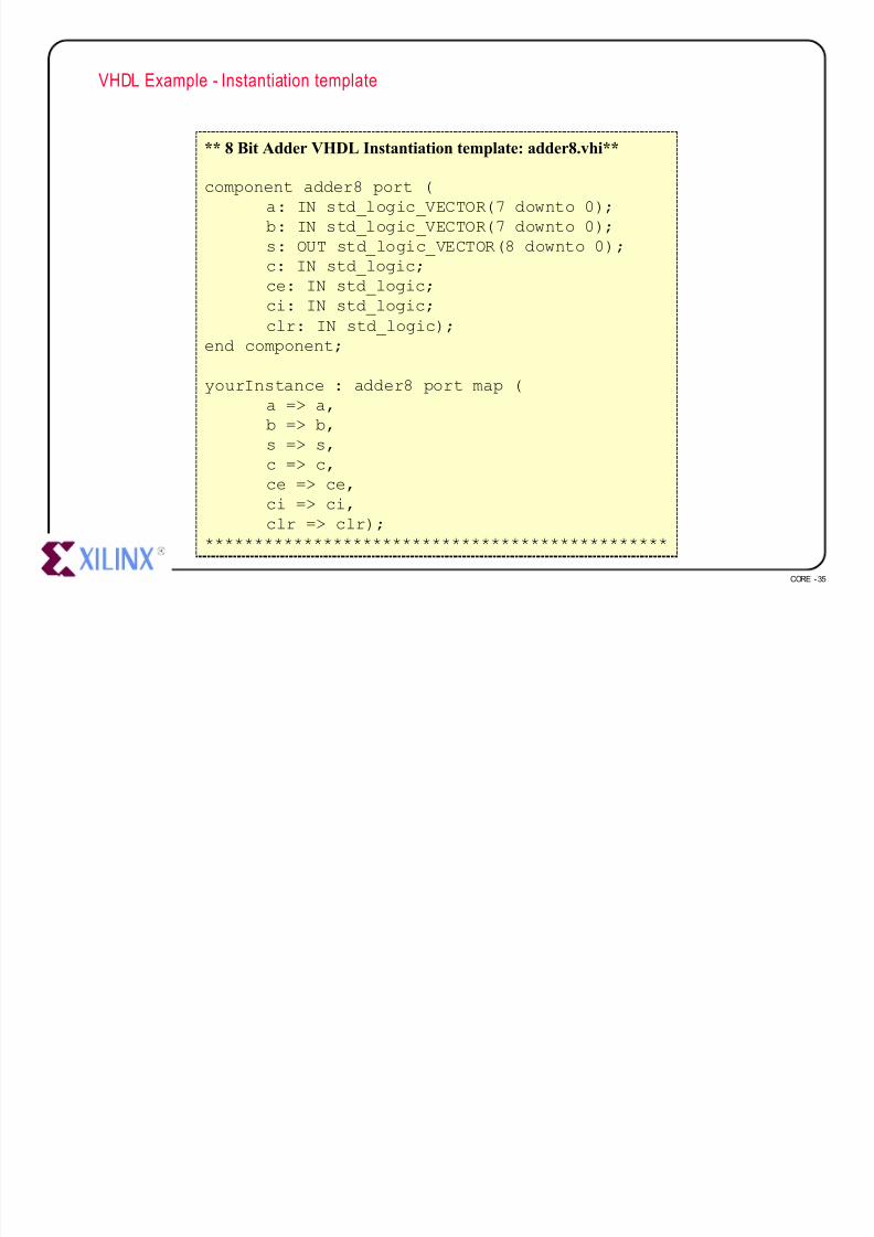
VHDL Example - Instantiation template
** 8 Bit Adder VHDL Instantiation template: adder8.vhi**
component adder8 port (a: IN std_logic_VECTOR(7 downto 0);b: IN std_logic_VECTOR(7 downto 0);s: OUT std_logic_VECTOR(8 downto 0);c: IN std_logic;ce: IN std_logic;
ci: IN std_logic;clr: IN std_logic);
end component;
yourInstance : adder8 port map (a => a,b => b,s => s,
c => c,ce => ce,ci => ci,clr => clr);
***********************************************
7/27/2019 07core
http://slidepdf.com/reader/full/07core 36/39
CORE -36
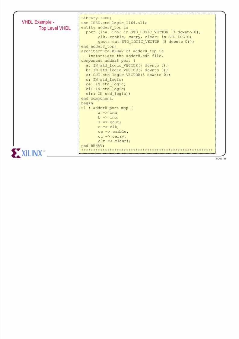
VHDL Example -
Top Level VHDL
Library IEEE;
use IEEE.std_logic_1164.all;entity adder8_top is
port (ina, inb: in STD_LOGIC_VECTOR (7 downto 0);
clk, enable, carry, clear: in STD_LOGIC;
qout: out STD_LOGIC_VECTOR (8 downto 0));end adder8_top;
architecture BEHAV of adder8_top is
-- Instantiate the adder8.edn file.
component adder8 port (
a: IN std_logic_VECTOR(7 downto 0);
b: IN std_logic_VECTOR(7 downto 0);
s: OUT std_logic_VECTOR(8 downto 0);
c: IN std_logic;
ce: IN std_logic;ci: IN std_logic;
clr: IN std_logic);
end component;
begin
u1 : adder8 port map (
a => ina,
b => inb,
s => qout,
c => clk,ce => enable,
ci => carry,clr => clear);
end BEHAV;
********************************************************

7/27/2019 07core
http://slidepdf.com/reader/full/07core 37/39
CORE -37
Verilog Example - Instantiation template
** 8 Bit Adder Verilog Instantiation template: adder8.vei **
module adder8 ( a, b, s, c, ce, ci, clr);input [7:0] a;input [7:0] b;output [8:0] s;input c;input ce;input ci;
input clr;endmodule
// The following is an example of an instantiation :adder8 YourInstanceName (
.a(a),
.b(b),
.s(s),
.c(c),
.ce(ce),
.ci(ci),
.clr(clr));
***********************************************

7/27/2019 07core
http://slidepdf.com/reader/full/07core 38/39
CORE -38
Verilog Example -
Top Level Verilog
Instantiation Module
Declaration
********** Top Level Verilog file: adder8_top.v ******
module adder8_top(ina, inb, clk, enable, carry, clear, qout);
input [7:0] ina;
input [7:0] inb;
input clk;input enable;
input carry;input clear;
output [8:0] qout;
//instantiate the adder8.xnf file
adder8 U1 (
.a(ina),
.b(inb),
.s(qout),
.c(clk),
.ce(enable),
.ci(carry),
.clr(clear));
endmodule
********************************************************
******** Instantiation Module Declaration: adder8.v ************
module adder8 ( a, b, s, c, ce, ci, clr);
input [7:0] a;
input [7:0] b;
output [8:0] s;input c;
input ce;
input ci;
input clr;endmodule
***********************************************

7/27/2019 07core
http://slidepdf.com/reader/full/07core 39/39
CORE -39
Foundation HDL Flow IV
u 6. Compiling the Design in Foundation Express• 1. Create a new project or open an existing one in Foundation Express.
• 2. Add all HDL files to be synthesized for the project.Note: Do NOT add the EDIF files created by the CORE Generator System to theExpress pro ject. Also, do NOT add any HDL simu lation fi les.
• 3. Verilog Only: Add a .v module declaration file for each instantiated block.
• 4. Select the top level entity and select Create Implementation to generate a newimplementation.
• 5. Optimize the implementation.
• 6. Write out the EDIF file for this implementation.
• 7. The EDIF file written by Express and the EDIF file(s) createdby the CORE Generator System are required as inputs to the XACTstepM1 Implementation Tools, and should all be
located in the same directory when 1 the design is input to M1.