Embed Size (px)
Citation preview
OSL Dosimeters
12/11/2011
General
2
General
General
• Optically stimulated luminescence (OSL) is a methodology that can be employed in personnel dosimetry to determine the “dose of record.”
It is an alternative to thermoluminescent dosimetry
3
• It is an alternative to thermoluminescent dosimetryand film dosimetry.
• Materials suitable for OSL are similar to those used in thermoluminescent dosimetry, i.e., they are crystalline solids. In many cases, the same material can be used either as an OSL dosimeter or a TLD.
General
General
• Optically stimulated luminescence (OSL) and thermoluminescence (TL) are very similar – the only difference is the manner in which the electrons are freed from their traps
4
electrons are freed from their traps.
• OSL dosimeters are of more recent vintage than thermoluminescent dosimeters (TLDs).
General
Basic Mechanism
• Radiation energy deposited in the material promotes electrons from the valence band to the conduction band.
Th l t t t i th b d
5
• These electrons move to traps in the band gap.
• The greater the radiation energy absorbed (dose),
the greater the number of trapped electrons.
• When it is time to assess the dose, the trapped electrons are freed by exposing the dosimeter to light.
General
Basic Mechanism
• When the electrons are freed, they fall to a lower energy level and emit light photons.
• The intensity of the emitted light is measured and d t l l t th d
6
used to calculate the dose.
• Not all the electrons are freed from their traps. If the light output from the OSL dosimeter is analyzed over a short period of time, many electrons will remain trapped. This means that the dosimeter can be reread many times without a significant loss of signal.
General
Advantages of OSL Dosimeters
• OSL dosimeters can be read at room temperature. This simplifies the design of the equipment.
• No need for nitrogen gas.
7
• The use of OSL powders deposited in thin layers creates a two-dimensional detector with imaging capabilities much like film.
• No correction factors are needed for individual elements.
General
Advantages of OSL Dosimeters
• Unlike a TLD, OSL dosimeters can be reread multiple times.
Depending on the illumination conditions, there
8
will be a decrease of signal of less than one percent in a second reading.
Used OSL badges are often archived for several years.
• No fading except in extreme temperatures.
• No annealing required.
General
Disadvantages of OSL Dosimeters
• The OSL system is more expensive to use than TLDs.
• Workers might wonder why doses are being
9
reported with OSL dosimeters when no dose was reported with TL dosimeters.
• Uncertainties in background brings into question the validity of reporting doses of a few mrem.
Absorption and Trapping of Radiation Energy
10
CONDUCTION BAND
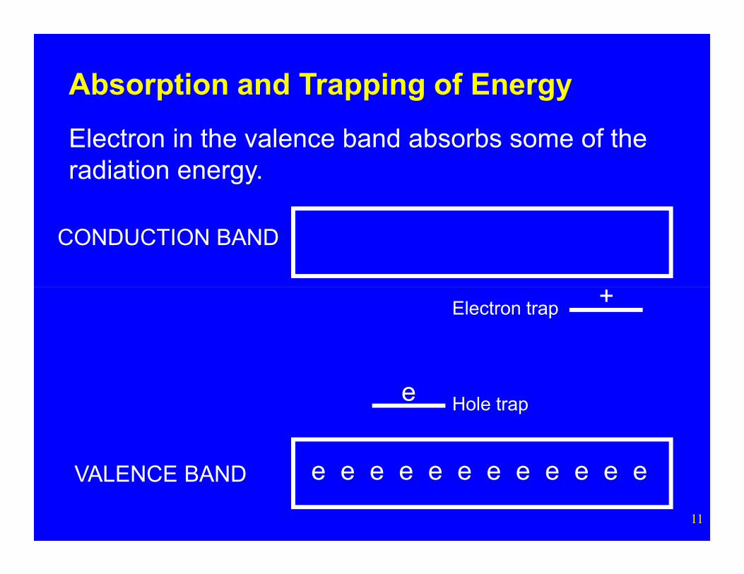
Absorption and Trapping of Energy
Electron in the valence band absorbs some of the radiation energy.
11
e e e e e e e e e e e eVALENCE BAND
Hole trap
Electron trap
e
+
CONDUCTION BAND
e
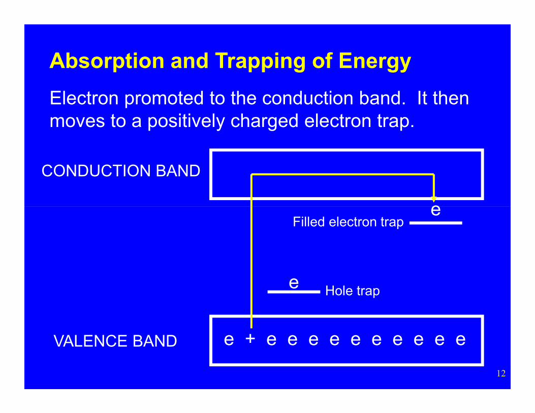
Absorption and Trapping of Energy
Electron promoted to the conduction band. It then moves to a positively charged electron trap.
12
e + e e e e e e e e e eVALENCE BAND
Hole trap
Filled electron trap
e
e
CONDUCTION BAND
e
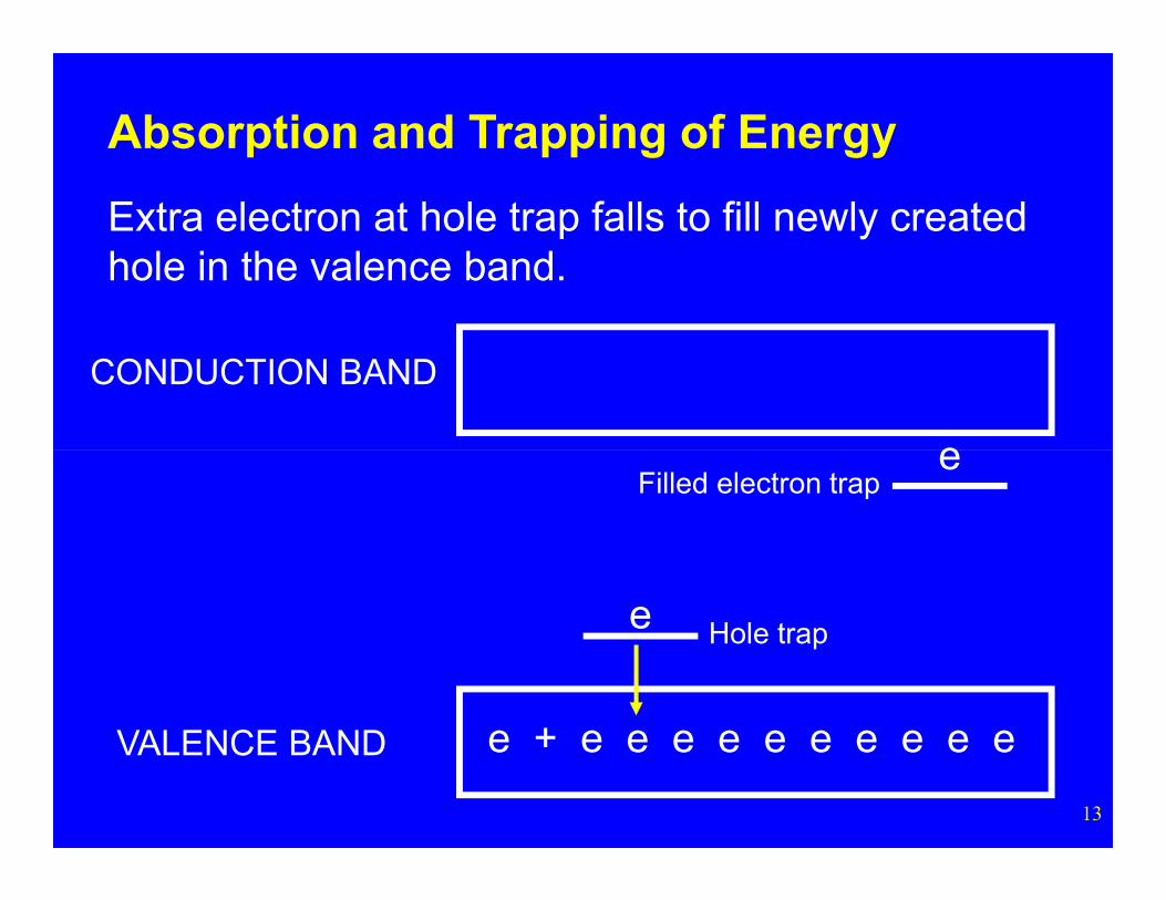
Absorption and Trapping of Energy
Extra electron at hole trap falls to fill newly created hole in the valence band.
13
e + e e e e e e e e e eVALENCE BAND
Hole trap
Filled electron trap
e
e
CONDUCTION BAND
e
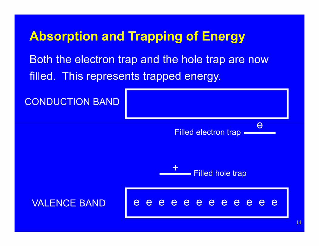
Absorption and Trapping of Energy
Both the electron trap and the hole trap are now
filled. This represents trapped energy.
14
e e e e e e e e e e e eVALENCE BAND
Filled hole trap
Filled electron trap
+
e
Absorption and Trapping of Energy
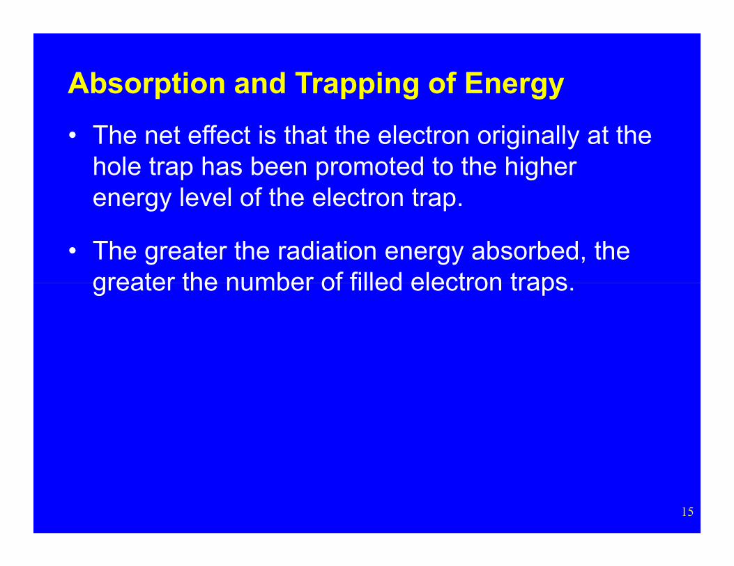
• The net effect is that the electron originally at the hole trap has been promoted to the higher energy level of the electron trap.
• The greater the radiation energy absorbed, the greater the number of filled electron traps
15
greater the number of filled electron traps.
Optically Stimulated Light Emission
16
CONDUCTION BAND
e
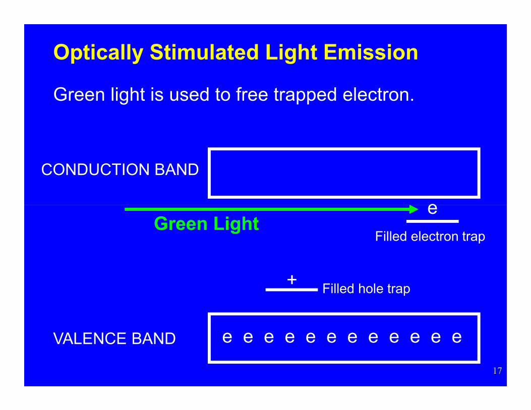
Optically Stimulated Light Emission
Green light is used to free trapped electron.
17
e e e e e e e e e e e eVALENCE BAND
Filled hole trap
Filled electron trap
+
eGreen Light
CONDUCTION BAND
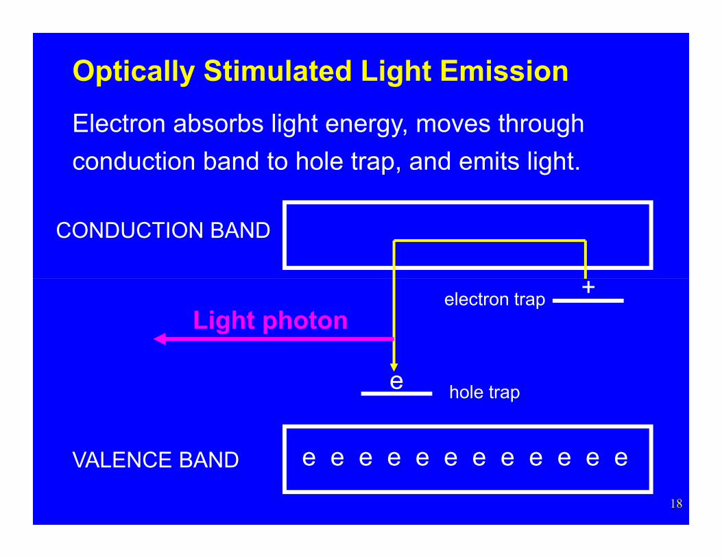
Optically Stimulated Light Emission
Electron absorbs light energy, moves through
conduction band to hole trap, and emits light.
18
e e e e e e e e e e e eVALENCE BAND
hole trap
electron trap +
e
Light photon
or
19
CONDUCTION BAND
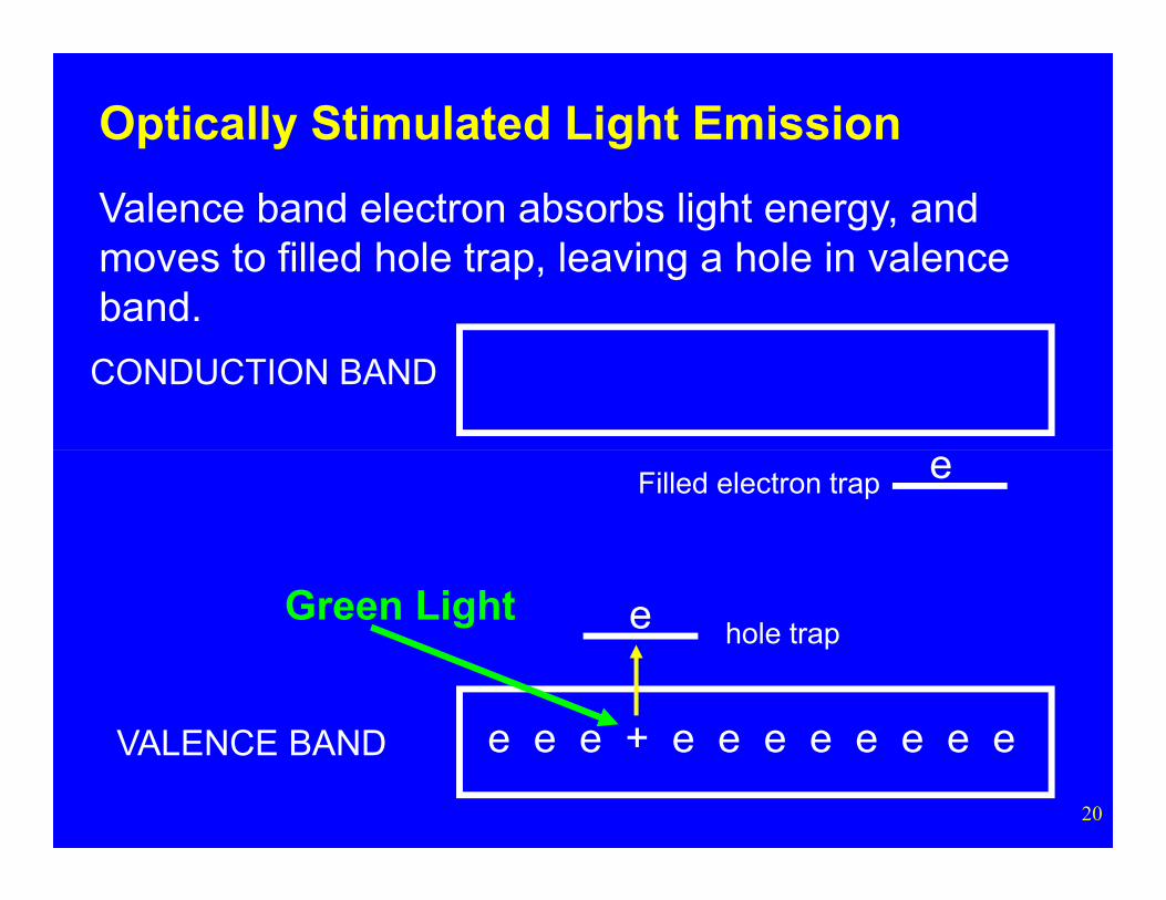
Optically Stimulated Light Emission
Valence band electron absorbs light energy, and moves to filled hole trap, leaving a hole in valence band.
20
e e e + e e e e e e e eVALENCE BAND
hole trap
Filled electron trap
e
e
Green Light
CONDUCTION BAND
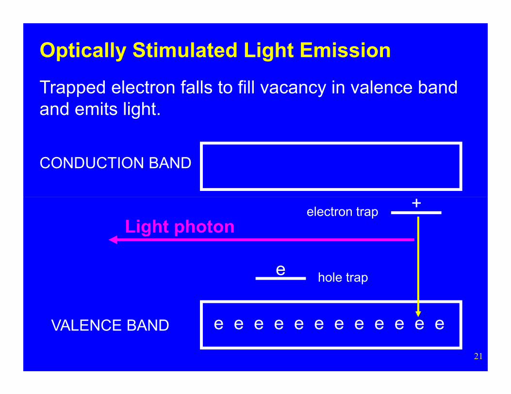
Optically Stimulated Light Emission
Trapped electron falls to fill vacancy in valence band and emits light.
21
e e e e e e e e e e e eVALENCE BAND
hole trap
electron trap
e
+Light photon
Optically Stimulated Light Emission
The measured intensity of the emitted light (i.e., the number of photons emitted) is used to estimate the dose.
22
Landauer OSL Dosimeters
23
Dosimeters
Landauer OSL Dosimeters
General
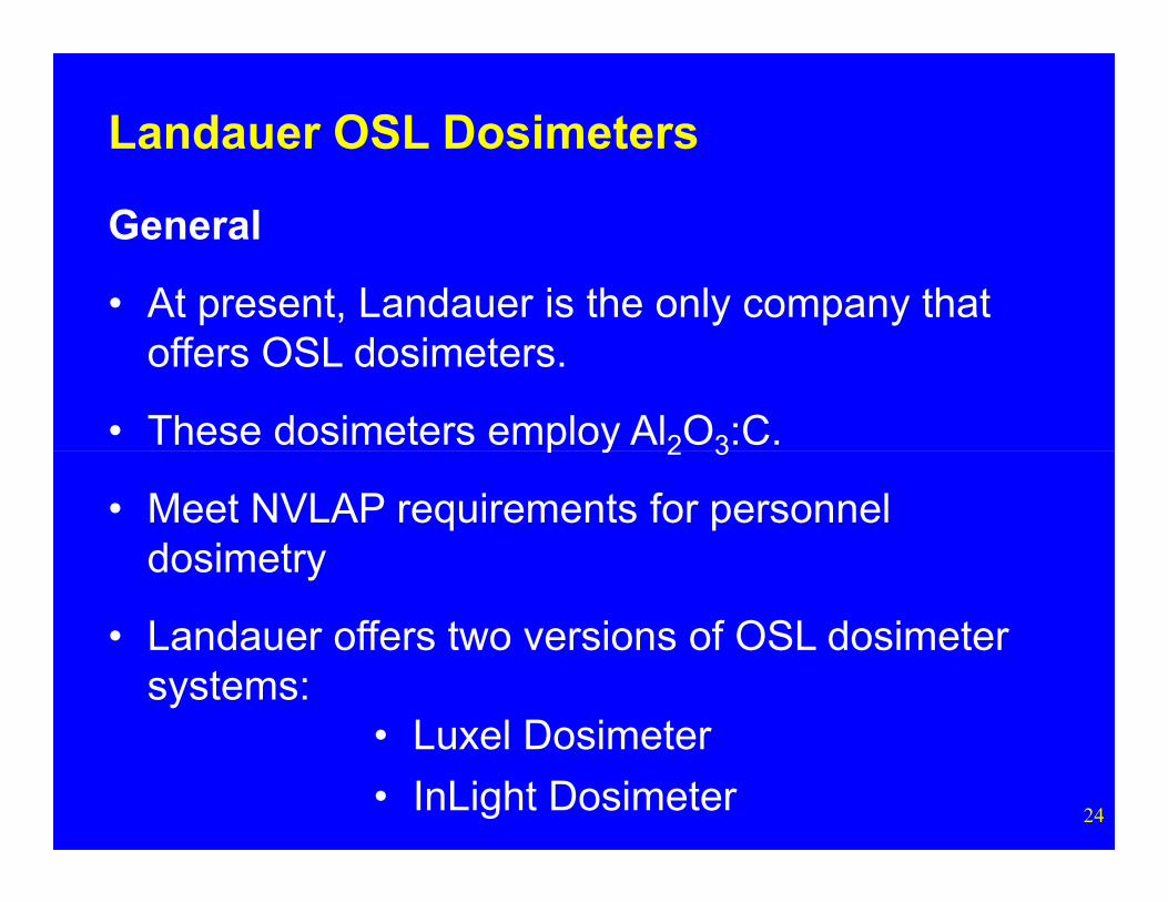
• At present, Landauer is the only company that offers OSL dosimeters.
• These dosimeters employ Al2O3:C.
24
p y 2 3
• Meet NVLAP requirements for personnel dosimetry
• Landauer offers two versions of OSL dosimeter systems:
• Luxel Dosimeter
• InLight Dosimeter

Luxel OSLDosimeters
25
Dosimeters
Landauer OSL Dosimeters
General
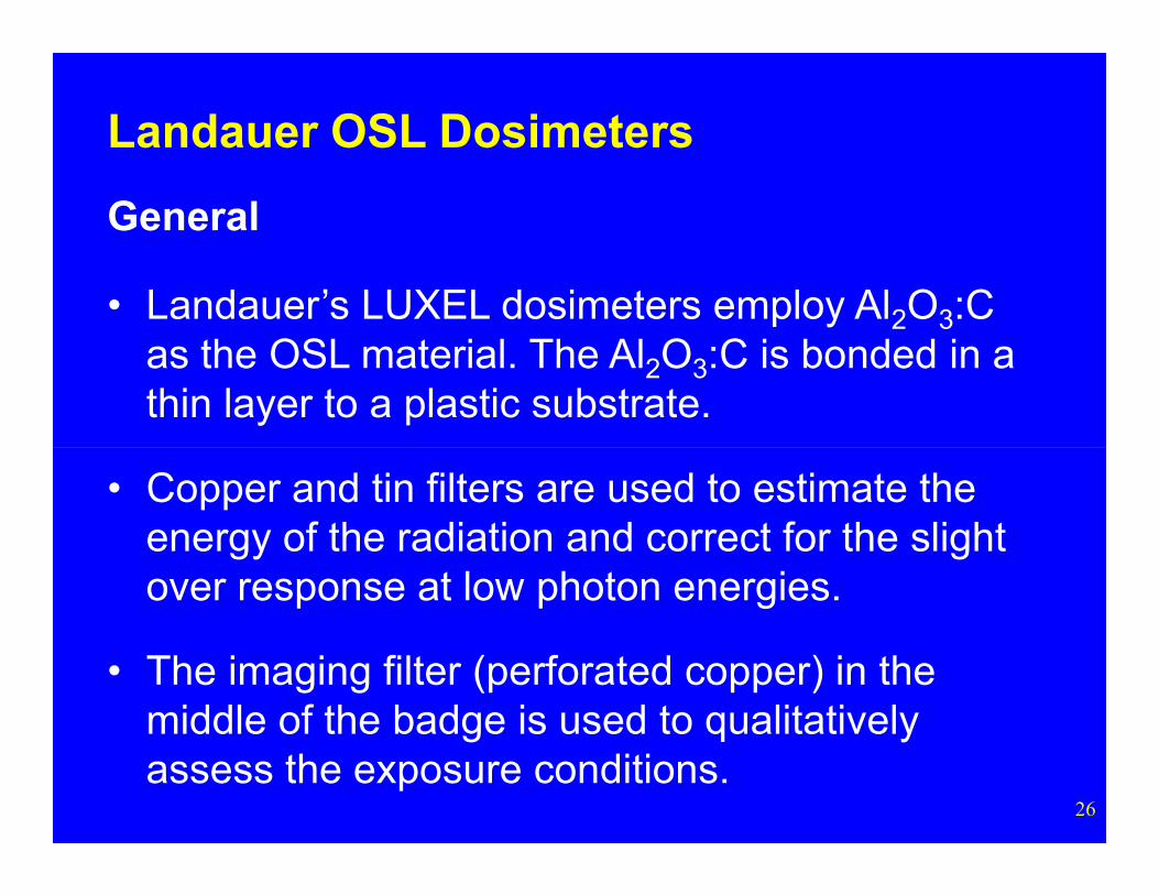
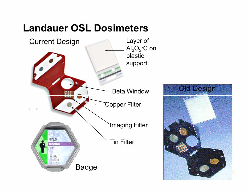
• Landauer’s LUXEL dosimeters employ Al2O3:C as the OSL material. The Al2O3:C is bonded in a thin layer to a plastic substrate.
26
• Copper and tin filters are used to estimate the energy of the radiation and correct for the slight over response at low photon energies.
• The imaging filter (perforated copper) in the middle of the badge is used to qualitatively assess the exposure conditions.
Landauer OSL DosimetersCurrent Design
Old DesignBeta Window
Layer of Al2O3:C on plastic support
27Badge
Imaging Filter
Copper Filter
Tin Filter
Landauer OSL Dosimeters
General
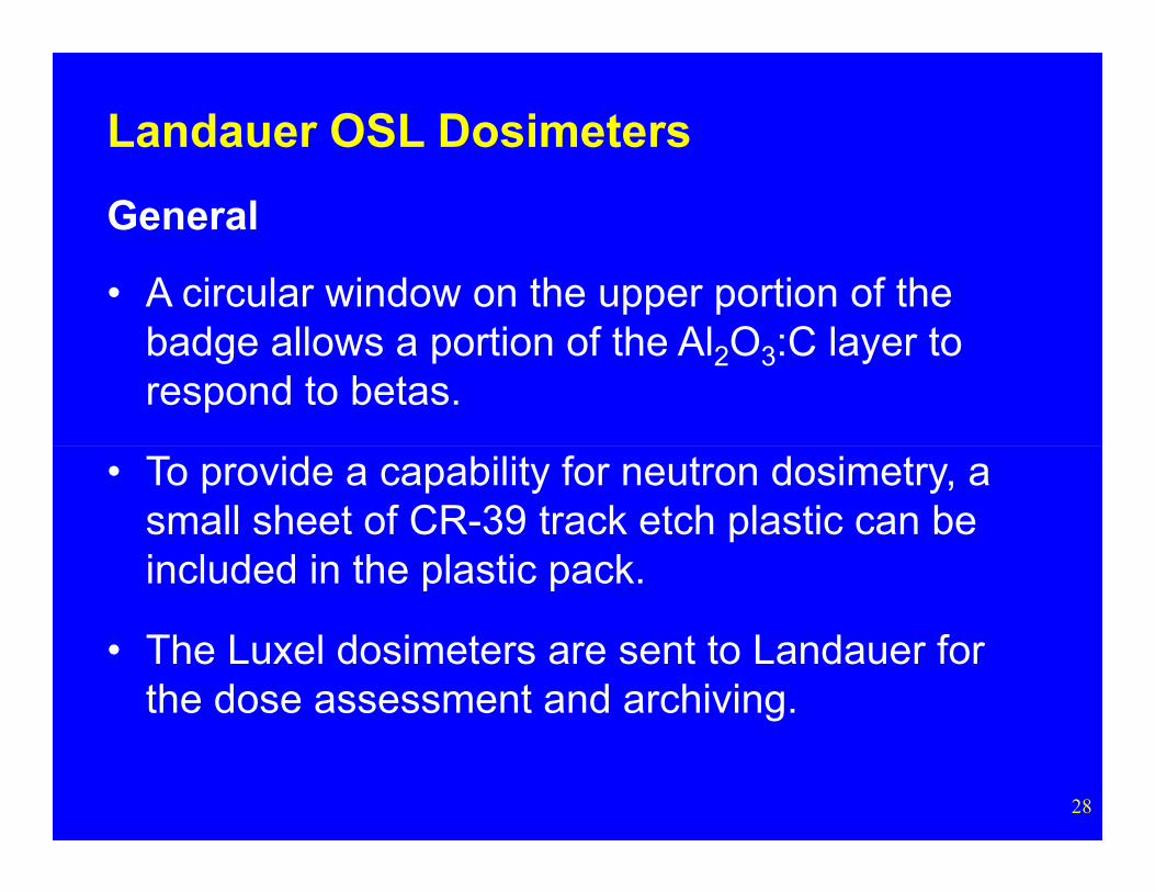
• A circular window on the upper portion of the badge allows a portion of the Al2O3:C layer to respond to betas.
28
• To provide a capability for neutron dosimetry, a small sheet of CR-39 track etch plastic can be included in the plastic pack.
• The Luxel dosimeters are sent to Landauer for the dose assessment and archiving.
Landauer OSL Dosimeters
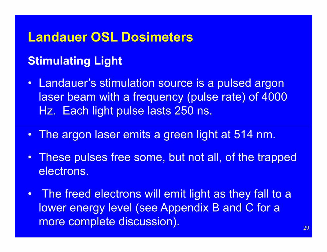
Stimulating Light
• Landauer’s stimulation source is a pulsed argon laser beam with a frequency (pulse rate) of 4000 Hz. Each light pulse lasts 250 ns.
29
• The argon laser emits a green light at 514 nm.
• These pulses free some, but not all, of the trapped electrons.
• The freed electrons will emit light as they fall to a lower energy level (see Appendix B and C for a more complete discussion).
Landauer OSL Dosimeters
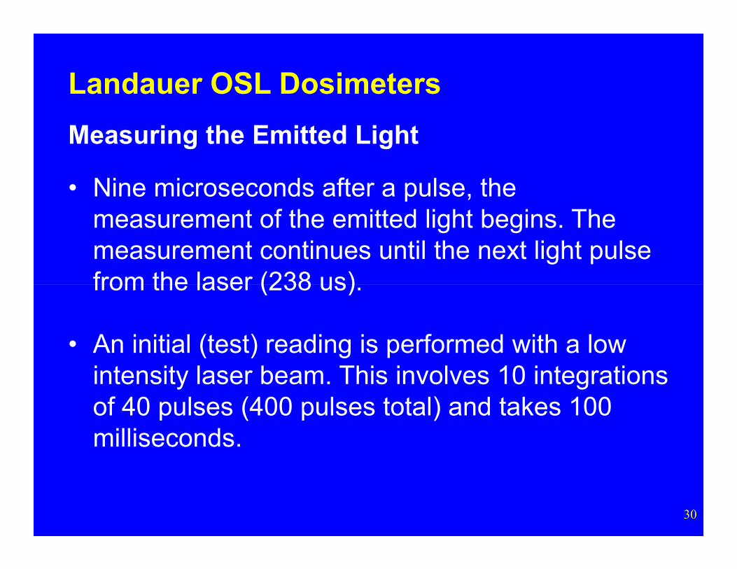
Measuring the Emitted Light
• Nine microseconds after a pulse, the measurement of the emitted light begins. The measurement continues until the next light pulse from the laser (238 us)
30
from the laser (238 us).
• An initial (test) reading is performed with a low intensity laser beam. This involves 10 integrations of 40 pulses (400 pulses total) and takes 100 milliseconds.
Landauer OSL Dosimeters
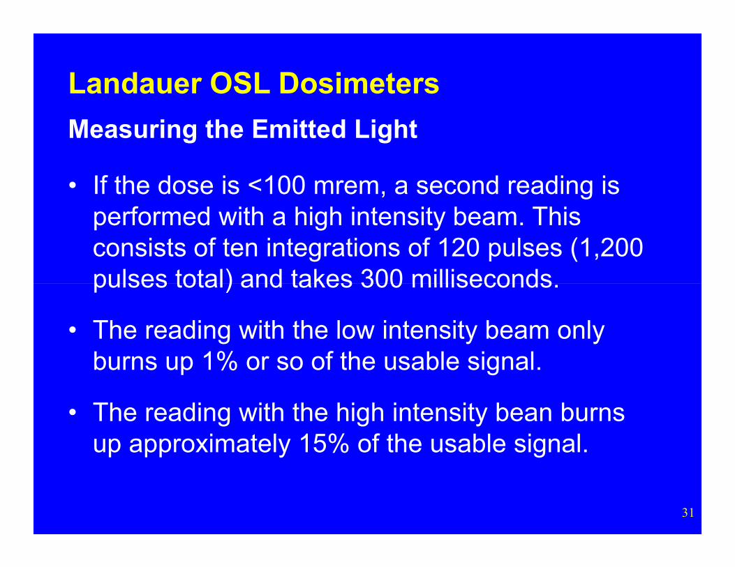
Measuring the Emitted Light
• If the dose is <100 mrem, a second reading is performed with a high intensity beam. This consists of ten integrations of 120 pulses (1,200 pulses total) and takes 300 milliseconds
31
pulses total) and takes 300 milliseconds.
• The reading with the low intensity beam only burns up 1% or so of the usable signal.
• The reading with the high intensity bean burns up approximately 15% of the usable signal.
Landauer OSL Dosimeters
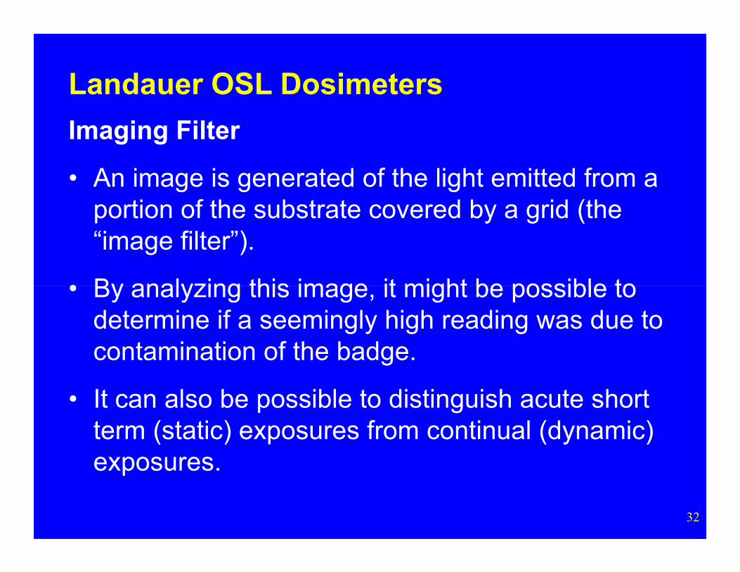
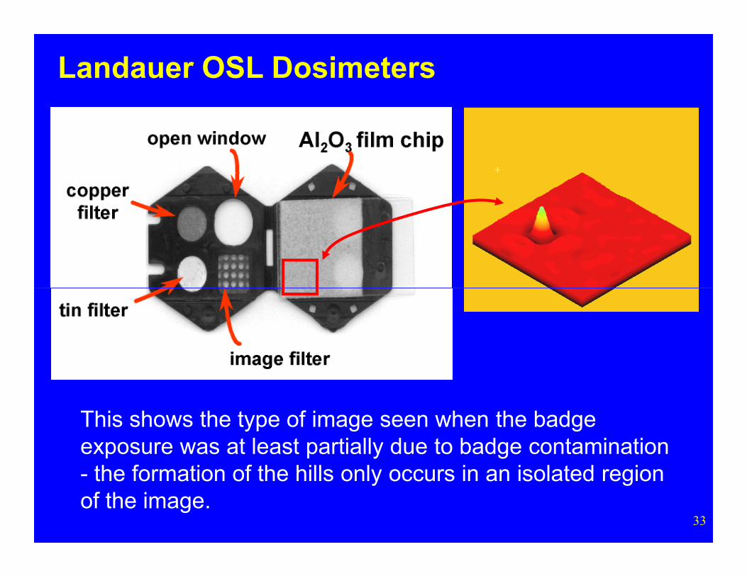
Imaging Filter
• An image is generated of the light emitted from a portion of the substrate covered by a grid (the “image filter”).
• By analyzing this image it might be possible to
32
• By analyzing this image, it might be possible to determine if a seemingly high reading was due to contamination of the badge.
• It can also be possible to distinguish acute short term (static) exposures from continual (dynamic) exposures.
Landauer OSL Dosimeters
33
This shows the type of image seen when the badge exposure was at least partially due to badge contamination - the formation of the hills only occurs in an isolated region of the image.
Landauer OSL Dosimeters
34
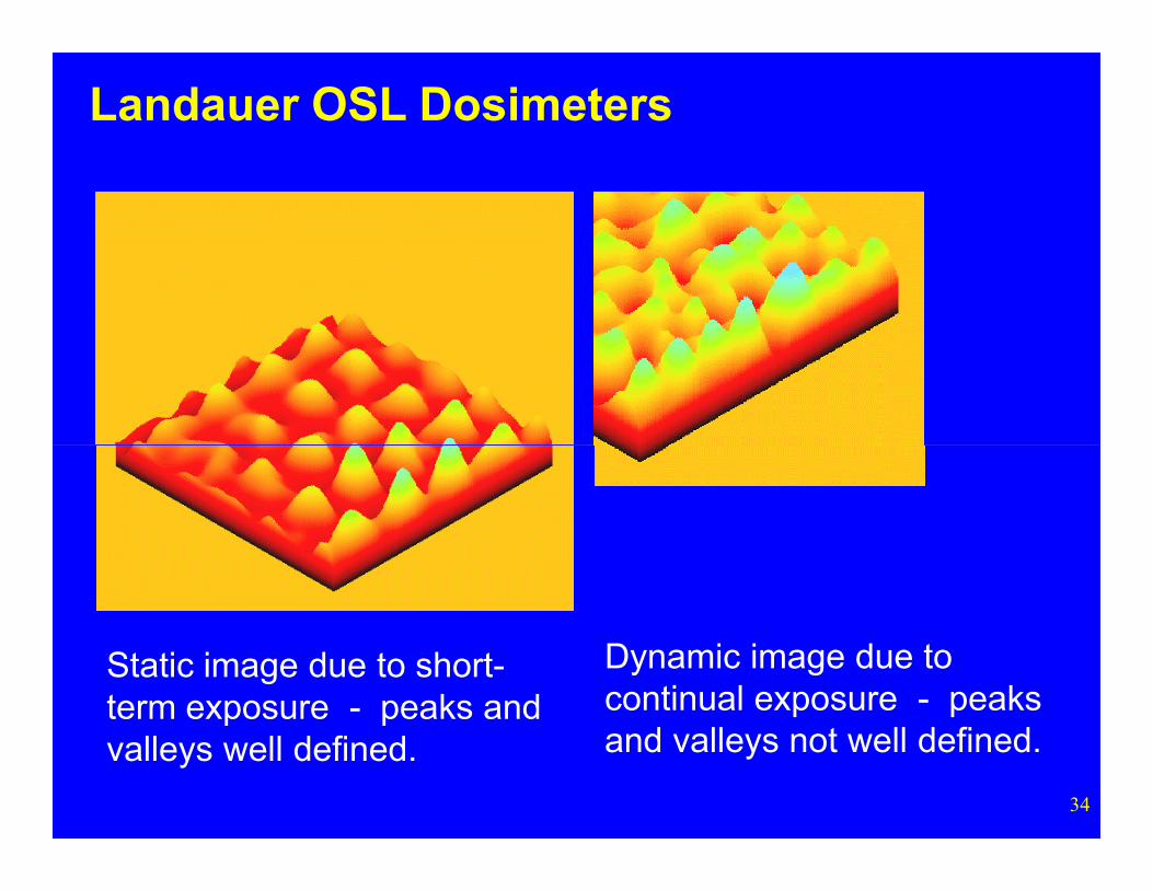
Dynamic image due to continual exposure - peaks and valleys not well defined.
Static image due to short-term exposure - peaks and valleys well defined.
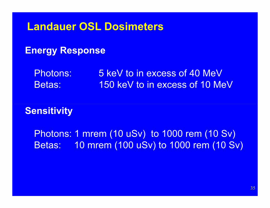
Energy Response
Photons: 5 keV to in excess of 40 MeVBetas: 150 keV to in excess of 10 MeV
Landauer OSL Dosimeters
35
Sensitivity
Photons: 1 mrem (10 uSv) to 1000 rem (10 Sv)Betas: 10 mrem (100 uSv) to 1000 rem (10 Sv)
InLight OSL Dosimeters
36
Dosimeters
InLight OSL Dosimeters
General
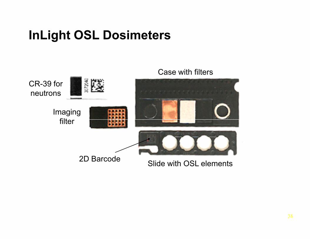
• Landauer’s InLight dosimeters, like their Luxel dosimeters, employ Al2O3:C as the OSL material.
• A difference is that the InLight system employs
37
g y p ythe OSL elements on a slide in a Panasonic style four position dosimeter holder.
• Like the Panasonic TLD dosimeter, the InLight dosimeter case employs aluminum, copper and plastic filters over the four elements.
InLight OSL Dosimeters
Case with filters
CR-39 for neutrons
Imaging filt
38
Slide with OSL elements2D Barcode
filter
InLight OSL Dosimeters
General
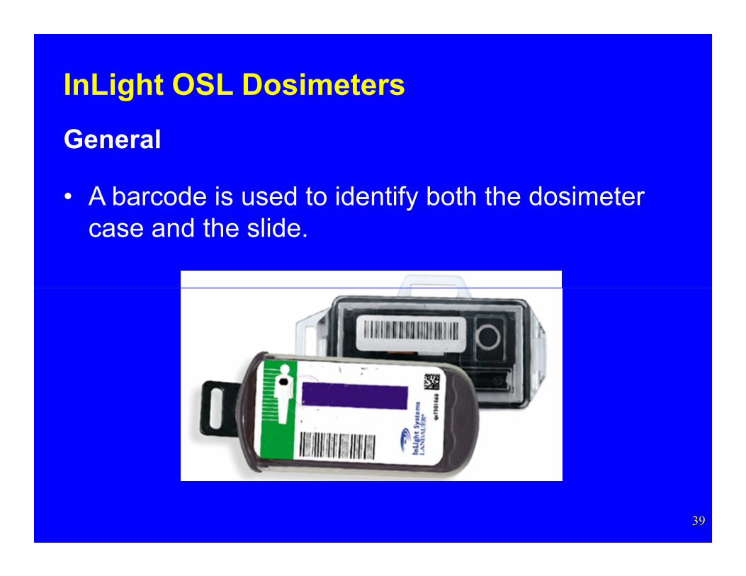
• A barcode is used to identify both the dosimeter case and the slide.
39
InLight OSL Dosimeters
Stimulating Light
• The InLight system employs a bank of green LEDs (525 nm) in a continuous emission mode. Since the intensity is lower than that of the laser used with the Luxel system longer read times are
40
with the Luxel system, longer read times are required.
• Use of LEDs eliminates laser safety issues.
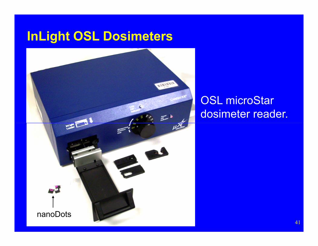
OSL microStar dosimeter reader.
InLight OSL Dosimeters
41nanoDots
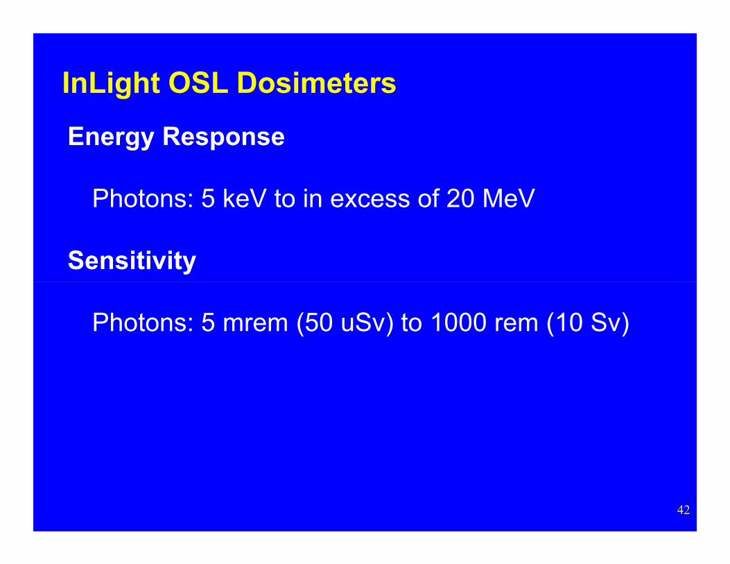
Energy Response
Photons: 5 keV to in excess of 20 MeV
Sensitivity
InLight OSL Dosimeters
42
Photons: 5 mrem (50 uSv) to 1000 rem (10 Sv)
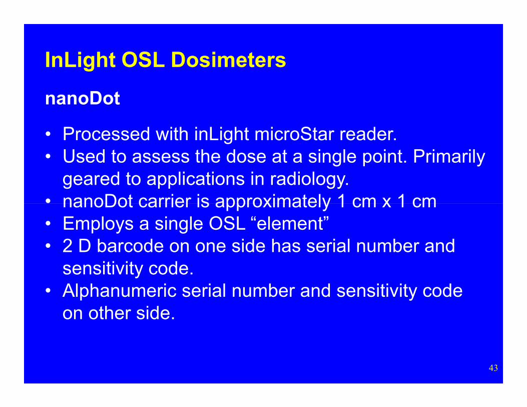
InLight OSL Dosimeters
nanoDot
• Processed with inLight microStar reader.• Used to assess the dose at a single point. Primarily
geared to applications in radiology.• nanoDot carrier is approximately 1 cm x 1 cm
43
nanoDot carrier is approximately 1 cm x 1 cm• Employs a single OSL “element”• 2 D barcode on one side has serial number and
sensitivity code.• Alphanumeric serial number and sensitivity code
on other side.
References
44
References
Akselrod, A. et al. Optically Stimulated Luminescence Response of Al2O3 to Beta Radiation, Rad. Prot. Dos. 85(1-4):125-128; 1999.
Botter-Jensen, L. Luminescence Techniques: Instrumentation and Methods Radiation Measurements
45
27(5/6):749-768, 1997.
Botter-Jensen, L., Agersnap Larsen, N., Markey, B.G., and McKeever, S.W.S. Al2O3:C as a Sensitive Dosemeter for Rapid Assessment of Environmental Photon Dose RatesRadiation Measurements 27(2):295-298, 1997.
References
Bulur, E., and Goksu, H.Y. Pulsed Optically Stimulated Luminescence from Al2O3:C using Green Light Emitting Diodes Radiation Measurements 27(3):479-488, 1997.
McKeever, S.W.S. et al. Characterization of Al2O3 for Use in Thermally and Optically Stimulated Luminescence Dosimetry, Rad Prot Dos 84 (1 4): 163 168; 1999
46
Rad. Prot. Dos. 84 (1-4): 163-168; 1999.
McKeever, S.W.S. and Akselrod, M.S. Radiation Dosimetry Using pulsed Optically Stimulated Luminescence of Al2O3:CRad. Prot. Dos. 84 (1-4): 317-320; 1999.
McKeever, S.W.S. and Akselrod, M.S. Radiation Dosimetry Using pulsed Optically Stimulated Luminescence of Al2O3:CRad. Prot. Dos. 84 (1-4): 317-320; 1999.
References
Nuclear Regulatory Commission NRC Broadens Use of Dosimeters to Reflect New Advances in Technology NRC News No.00-157, October 11, 2000.
Nuclear Regulatory Commission 10 CFR Parts 34, 36, and 39 New Dosimetry Technology; Final Rule, Federal Register 65
47
(206): 63750-63752. October 24, 2000.
Summers, G.P. Thermoluminescence in Single Crystal Al2O3,
Rad. Prot. Dos. 8 (1): 69-80: 1984.
References
Yoder, R.C. Optically Stimulated Luminescence Dosimetry Unpublished Presentation
Zelac, R.E. and R. Craig Optically Stimulated Luminescence Dosimetry in Radiation Instruments J. Higginbotham ed. HPS Summer School Proceedings 1996.
48
Appendix A:
49
Aluminum Oxide(Al2O3)
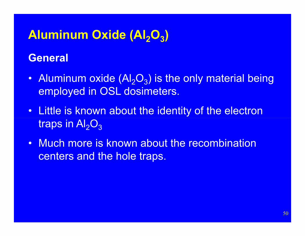
Aluminum Oxide (Al2O3)
General
• Aluminum oxide (Al2O3) is the only material being employed in OSL dosimeters.
• Little is known about the identity of the electron
50
traps in Al2O3
• Much more is known about the recombination centers and the hole traps.

Aluminum Oxide (Al2O3)
General
• Aluminum oxide (Al2O3) occurs naturally in only one form, corundum. Corundum is also known as alpha Al2O3.
• Ruby is corundum colored by chromium
51
• Ruby is corundum colored by chromium. Sapphire is corundum colored with titanium and iron.
• Al2O3 is used in thermoluminescent dosimeters and in optically stimulated luminescent dosimeters.
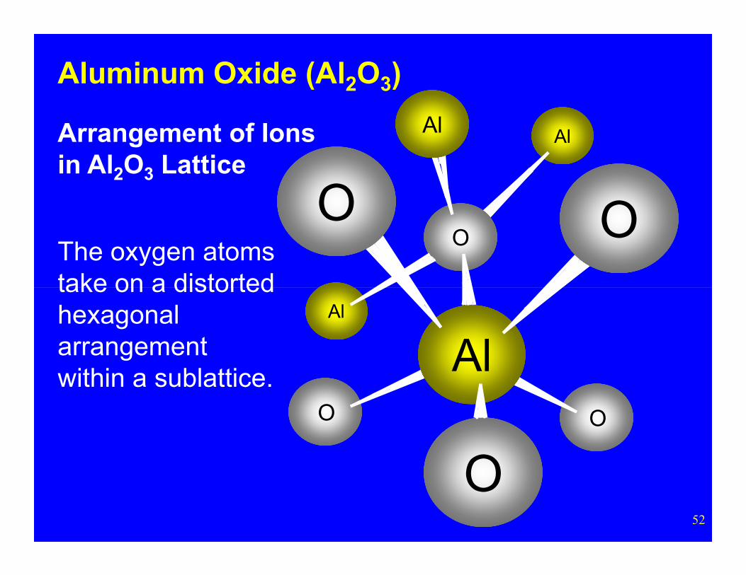
Al
OO
Al
O
Arrangement of Ionsin Al2O3 Lattice
The oxygen atoms take on a distorted
Aluminum Oxide (Al2O3)
52
O O
Al
Al
O
take on a distorted hexagonal arrangement within a sublattice.
Aluminum Oxide (Al2O3)
Advantages of Aluminum Oxide (Al2O3:C)
• Extremely durable.• Available in a variety of forms: single crystals,
powders, and thin layers bonded to a substrate.
53
substrate. • Extreme sensitivity.• Low fading at room temperatures.• Relatively low effective atomic number which
can reduce its energy dependence.• Simple emission spectrum.• Light output is linearly related to dose.
Aluminum Oxide (Al2O3)
General - Al2O3:C as a TLD
• Aluminum oxide activated with carbon (Al2O3:C) was first used as a TL material in 1990 (Akselrodet al.).
54
Primary Advantage as a TLD
• Extreme sensitivity: 40-60 times that of LiF TLD-100. This makes Al2O3:C particularly suitable as an environmental thermoluminescent dosimeter, and it is currently used for this purpose.
Aluminum Oxide (Al2O3)
Primary Disadvantages as a TLD
• Its TL output is heavily dependent on the heating (ramp) rate.
• It is extremely light sensitive.
55
Aluminum Oxide (Al2O3)
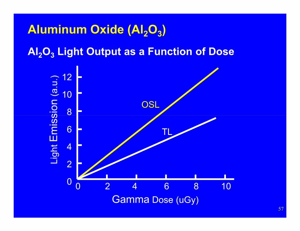
General - Al2O3:C as a OSL Dosimeter
• That Al2O3:C was susceptible to light induced fading, suggested the potential of this material for optically stimulated luminescence.
I f t Al O C h t iti it (li ht
56
• In fact, Al2O3:C has greater sensitivity (light output per unit dose) when used in the OSL mode than in the TL mode.
12
10
8sion
(a.u
.)
OSL
Aluminum Oxide (Al2O3)
Al2O3 Light Output as a Function of Dose
57
0 8642 10
6
4
2
0
Gamma Dose (uGy)
Ligh
t Em
iss
TL
Aluminum Oxide (Al2O3)
Stimulating Light
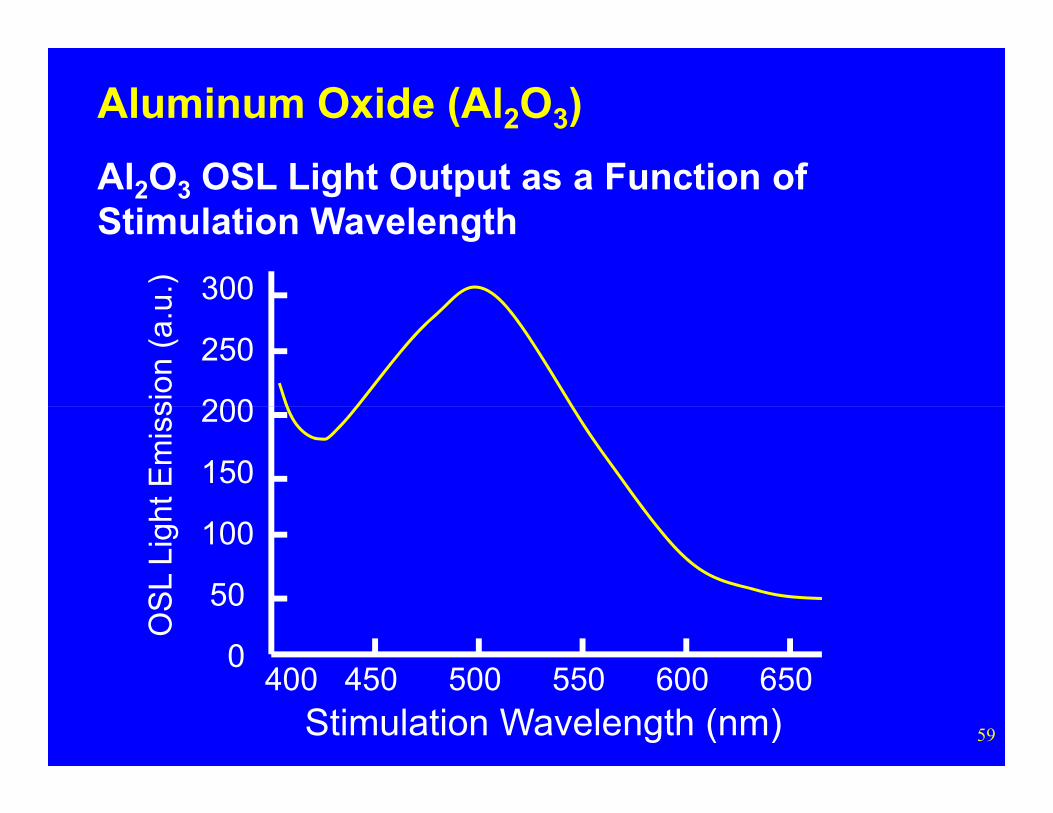
• The intensity of the emissions from Al2O3:C are greatest when stimulated by light with a wavelength of 500 nm.
B th it li ht t 514 4
58
• Because they emit light at 514.4 nm, argon lasers are the most common stimulating light source used with Al2O3:C.
300
250
200sion
(a.
u.)
Aluminum Oxide (Al2O3)
Al2O3 OSL Light Output as a Function of Stimulation Wavelength
59
400 600550500450 650
200
150
100
50
0
Stimulation Wavelength (nm)
OS
L Li
ght E
mis
s
100
on
Aluminum Oxide (Al2O3)
Light Emission
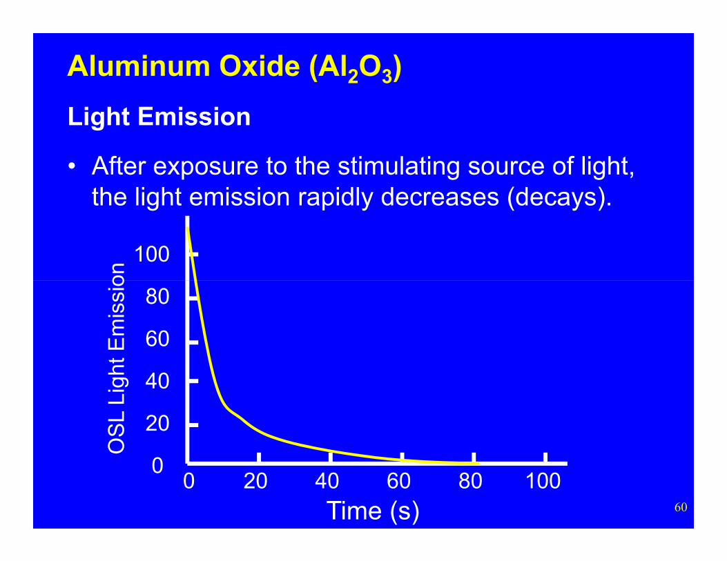
• After exposure to the stimulating source of light, the light emission rapidly decreases (decays).
60
0 80604020 100
80
60
40
20
0
Time (s)
OS
L Li
ght E
mis
sio
Aluminum Oxide (Al2O3)
Heat Induced Fading
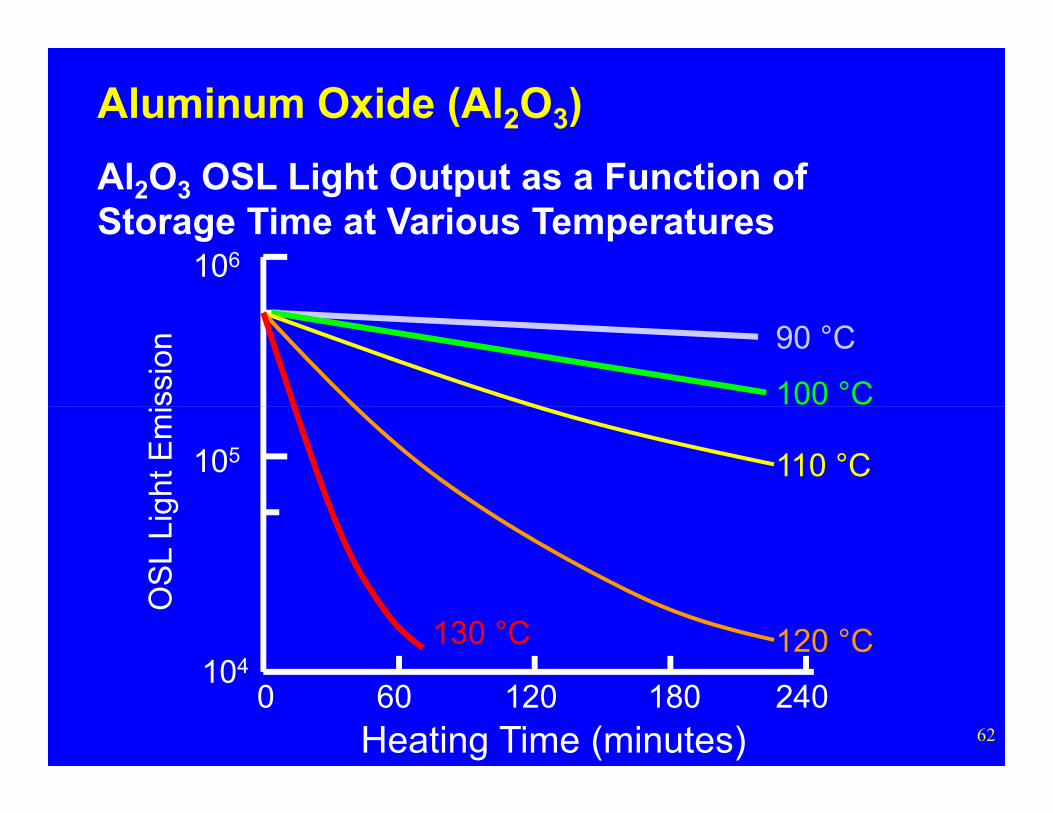
• As can be seen from the following figure, the loss of signal over time (fading) would be negligible if the Al2O3:C is maintained at room temperature Al2O3:C.
61
• However, storage at elevated temperatures for even short periods of time can significant reduce the OSL signal.
106
ssio
n
Aluminum Oxide (Al2O3)
Al2O3 OSL Light Output as a Function of Storage Time at Various Temperatures
90 °C
100 °C
62
0 18012060 240
105
104
Heating Time (minutes)
OS
L Li
ght
Em
i
110 °C
120 °C130 °C
Appendix B:
Recombination Centers
63
Recombination Centers
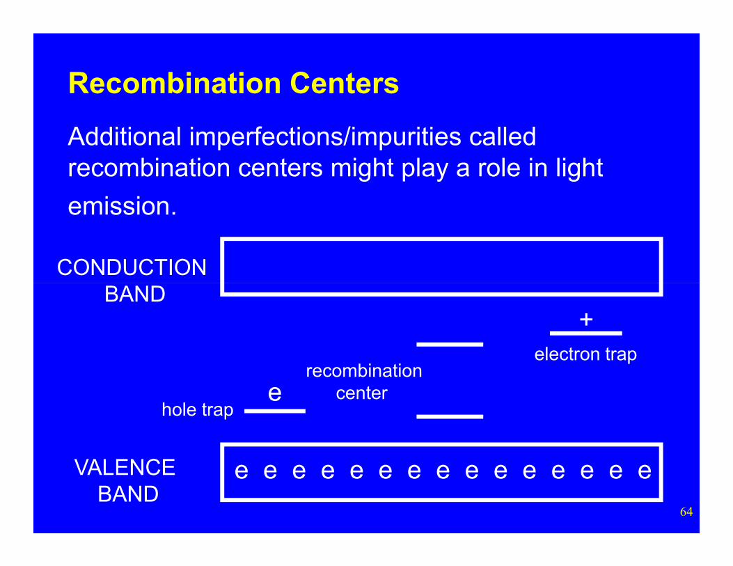
CONDUCTION
Recombination Centers
Additional imperfections/impurities called recombination centers might play a role in light
emission.
64
e e e e e e e e e e e e e e e
BAND
VALENCE BAND
hole trape
+
recombinationcenter
electron trap
CONDUCTION
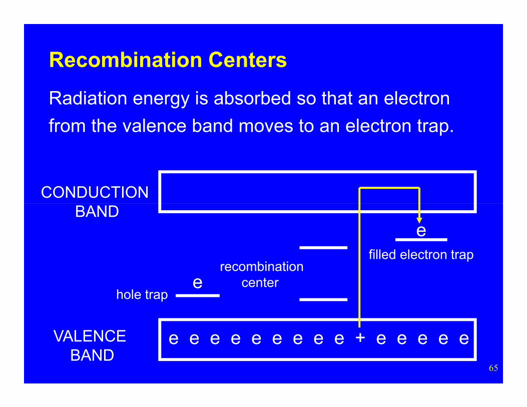
Recombination Centers
Radiation energy is absorbed so that an electron
from the valence band moves to an electron trap.
65
e e e e e e e e e + e e e e e
BAND
VALENCE BAND
hole trape
e
recombinationcenter
filled electron trap
CONDUCTION
Recombination Centers
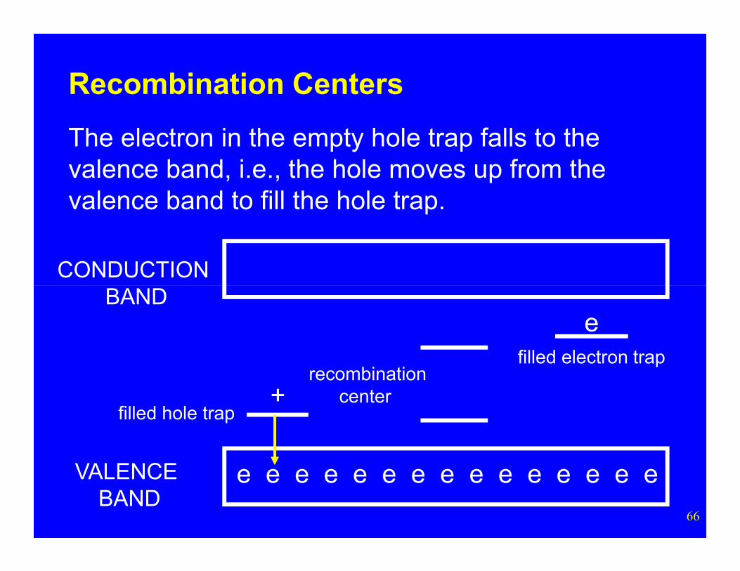
The electron in the empty hole trap falls to the valence band, i.e., the hole moves up from the valence band to fill the hole trap.
66
e e e e e e e e e e e e e e e
BAND
VALENCE BAND
filled hole trap+
e
recombinationcenter
filled electron trap
CONDUCTION
Recombination Centers
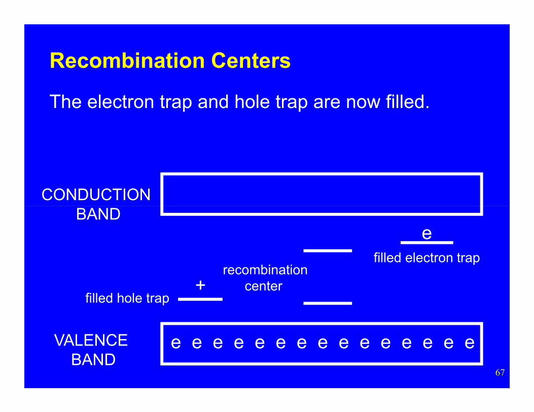
The electron trap and hole trap are now filled.
67
e e e e e e e e e e e e e e e
BAND
VALENCE BAND
filled hole trap+
e
recombinationcenter
filled electron trap
CONDUCTION
Recombination Centers
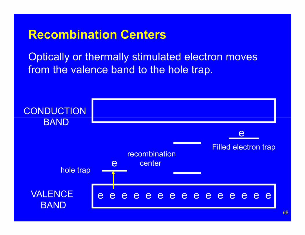
Optically or thermally stimulated electron moves from the valence band to the hole trap.
68
e e e e e e e e e e e e e e e
BAND
VALENCE BAND
hole trap
Filled electron traprecombination
center
e
e
CONDUCTION
Recombination Centers
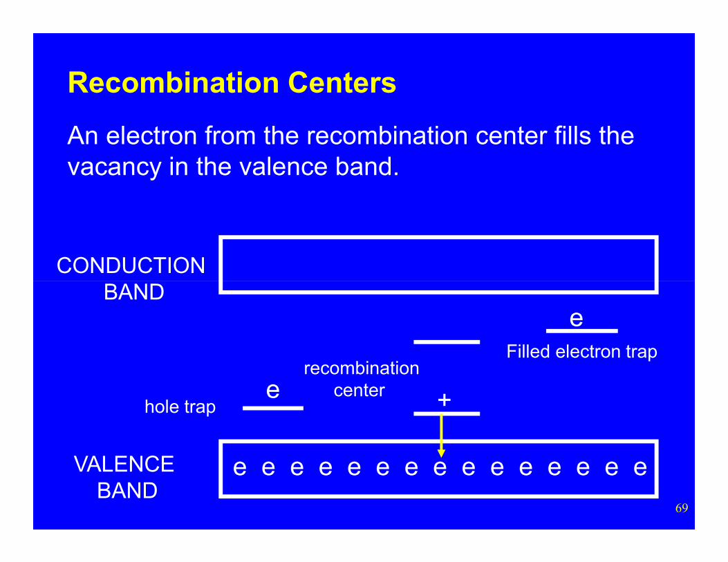
An electron from the recombination center fills the vacancy in the valence band.
69
e e e e e e e e e e e e e e e
BAND
VALENCE BAND
hole trap
Filled electron trap
+recombination
center
e
e
CONDUCTION
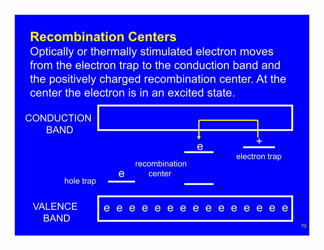
Recombination CentersOptically or thermally stimulated electron moves from the electron trap to the conduction band and the positively charged recombination center. At the center the electron is in an excited state.
70
e e e e e e e e e e e e e e e
BAND
VALENCE BAND
hole trap
electron traprecombination
center
e +
e
CONDUCTION
Recombination Centers
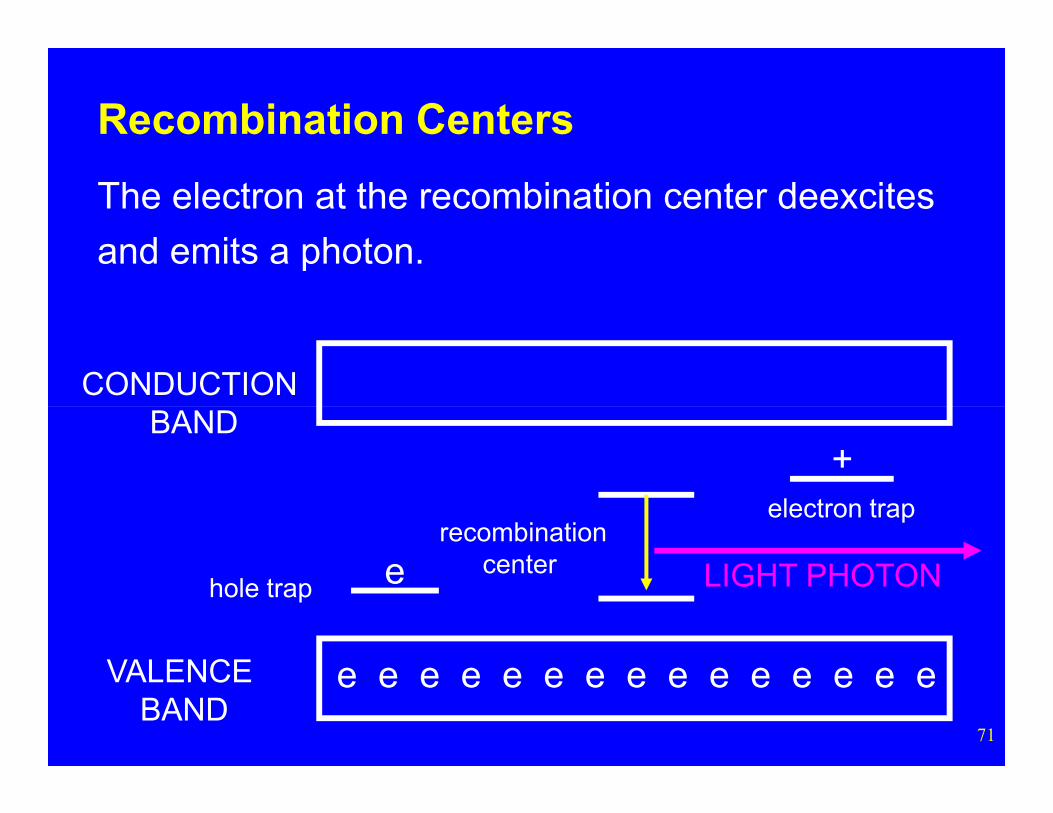
The electron at the recombination center deexcites
and emits a photon.
71
e e e e e e e e e e e e e e e
BAND
VALENCE BAND
hole trap
+
recombinationcenter
electron trap
LIGHT PHOTONe
Appendix C:
72
F Centers in Aluminum Oxide
F Centers in Al2O3
F+ (Recombination) Centers
• The recombination centers in aluminum oxide are defects (not impurities) in the crystalline lattice.
• Specifically a recombination center is a location
73
Specifically, a recombination center is a location where an oxygen (O2+) ion is missing, i.e., an oxygen vacancy.
• This recombination center is also known as an F+
center. The F is for “farben”, the German word for color - such sites can produce color.
F Centers in Al2O3
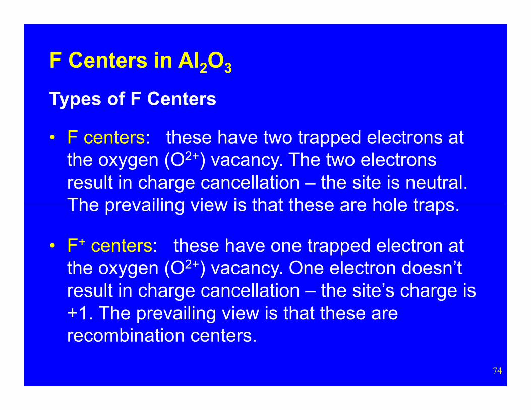
Types of F Centers
• F centers: these have two trapped electrons at the oxygen (O2+) vacancy. The two electrons result in charge cancellation – the site is neutral. The prevailing view is that these are hole traps
74
The prevailing view is that these are hole traps.
• F+ centers: these have one trapped electron at the oxygen (O2+) vacancy. One electron doesn’t result in charge cancellation – the site’s charge is +1. The prevailing view is that these are recombination centers.
F Centers in Al2O3
Energy States of F and F+ Centers
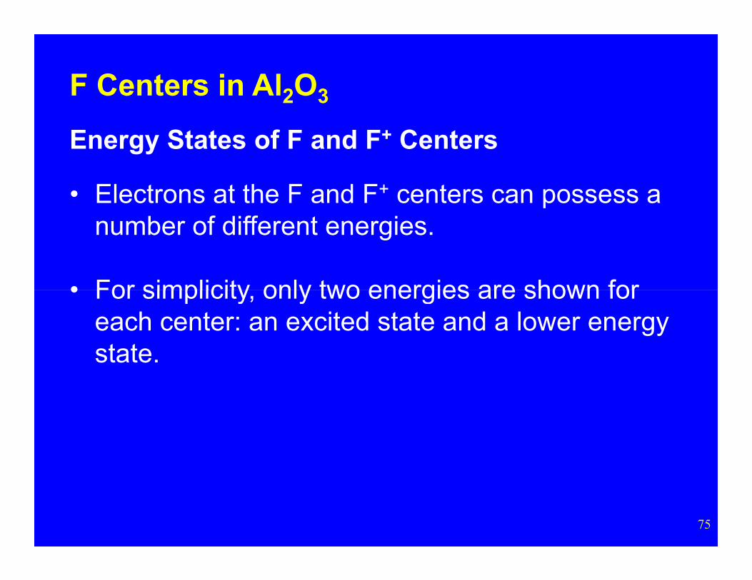
• Electrons at the F and F+ centers can possess a number of different energies.
• For simplicity only two energies are shown for
75
• For simplicity, only two energies are shown for each center: an excited state and a lower energy state.
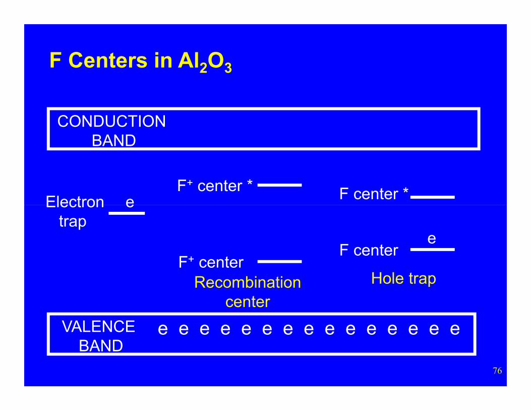
CONDUCTION BAND
F+ center * F center *
F Centers in Al2O3
eElectron
76
VALENCE BAND
F+ centerF center
e
e e e e e e e e e e e e e e e
Hole trapRecombinationcenter
eElectrontrap
F Centers in Al2O3
Production of F Centers
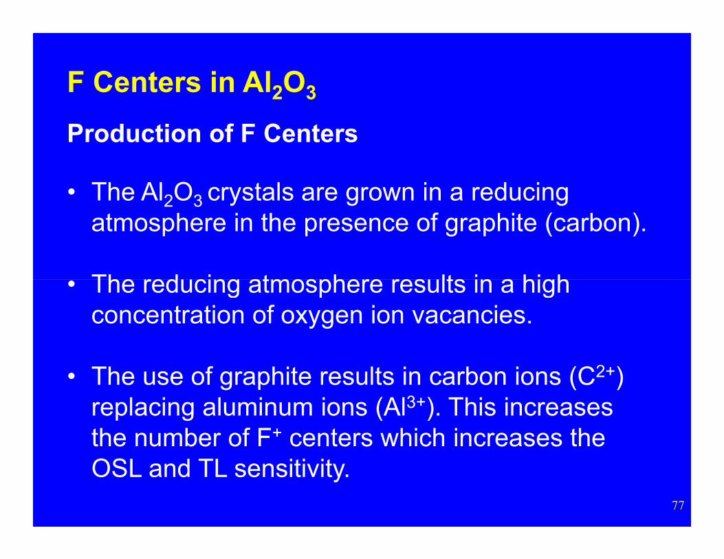
• The Al2O3 crystals are grown in a reducing atmosphere in the presence of graphite (carbon).
The reducing atmosphere results in a high
77
• The reducing atmosphere results in a high concentration of oxygen ion vacancies.
• The use of graphite results in carbon ions (C2+) replacing aluminum ions (Al3+). This increases the number of F+ centers which increases the OSL and TL sensitivity.
F Centers in Al2O3
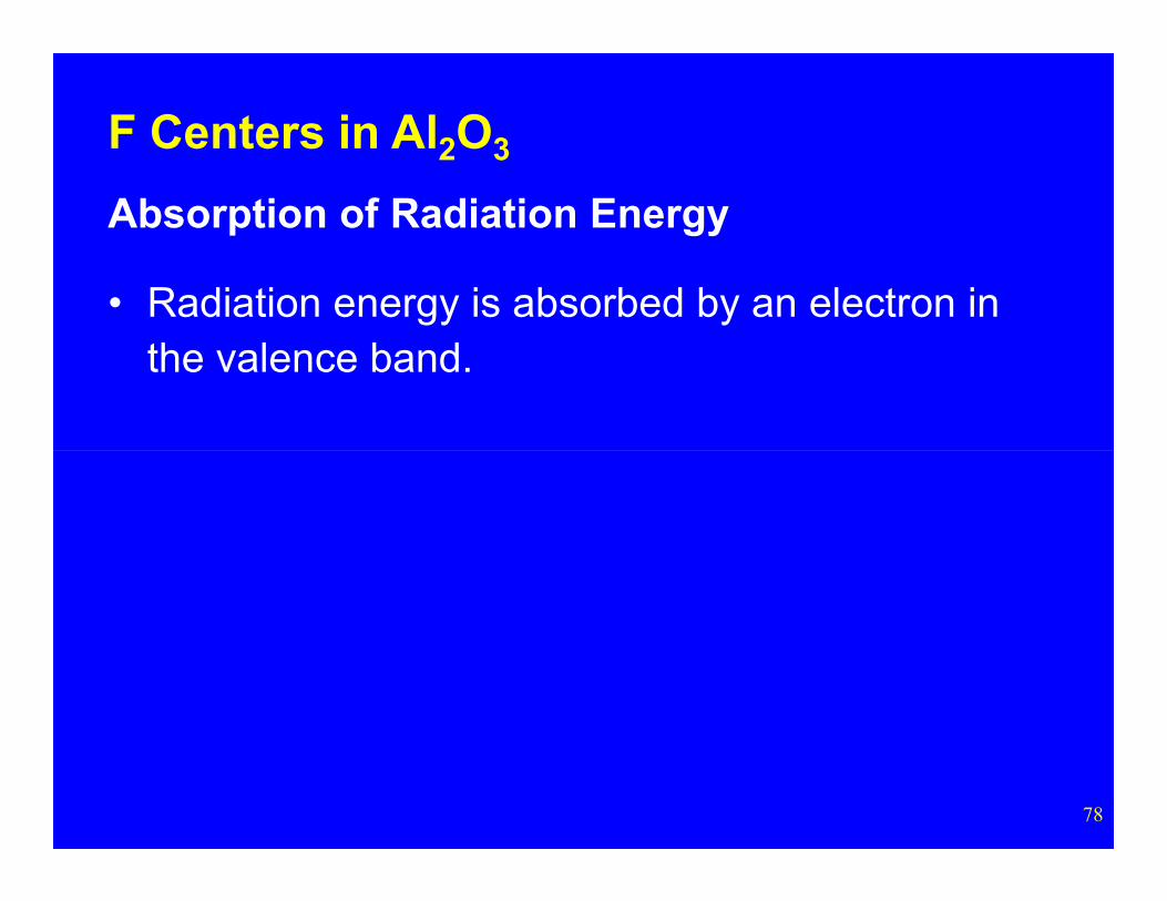
Absorption of Radiation Energy
• Radiation energy is absorbed by an electron in the valence band.
78
CONDUCTION BAND
F+ center * F t *e
F Centers in Al2O3
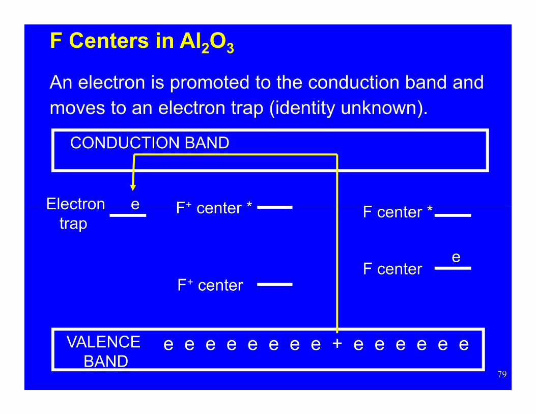
An electron is promoted to the conduction band and moves to an electron trap (identity unknown).
Electron
79
VALENCE BAND
F+ center
F center
F center
F center *
e
e e e e e e e e + e e e e e e
eElectrontrap
F+ center * F+ center *e
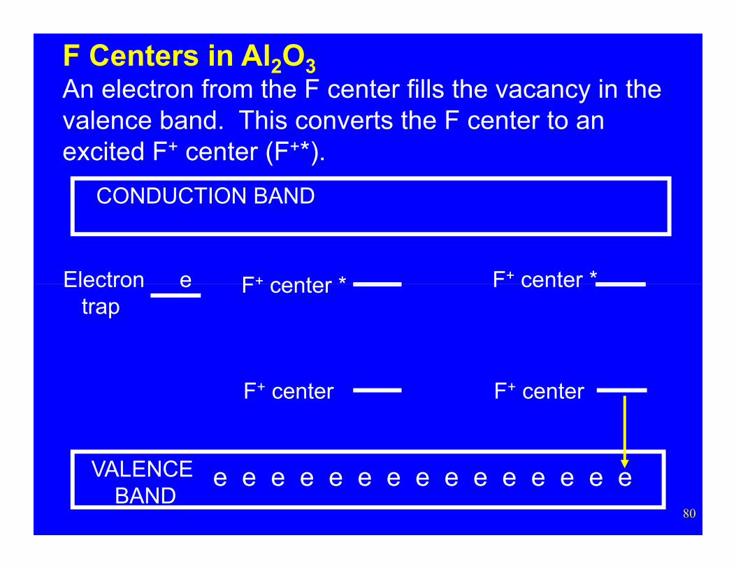
F Centers in Al2O3An electron from the F center fills the vacancy in the valence band. This converts the F center to an excited F+ center (F+*).
Electron
CONDUCTION BAND
80
VALENCE BAND
F+ center
F center
F+ center
F center
e e e e e e e e e e e e e e e
eElectrontrap
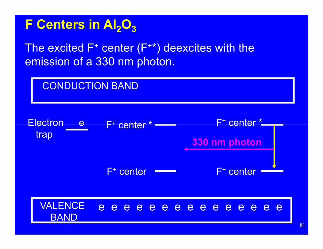
CONDUCTION BAND
F+ center * F+ center *e
F Centers in Al2O3
The excited F+ center (F+*) deexcites with the emission of a 330 nm photon.
Electron
81
VALENCE BAND
F+ center
F center
F+ center
F center
e e e e e e e e e e e e e e e
eElectrontrap
330 nm photon
F Centers in Al2O3
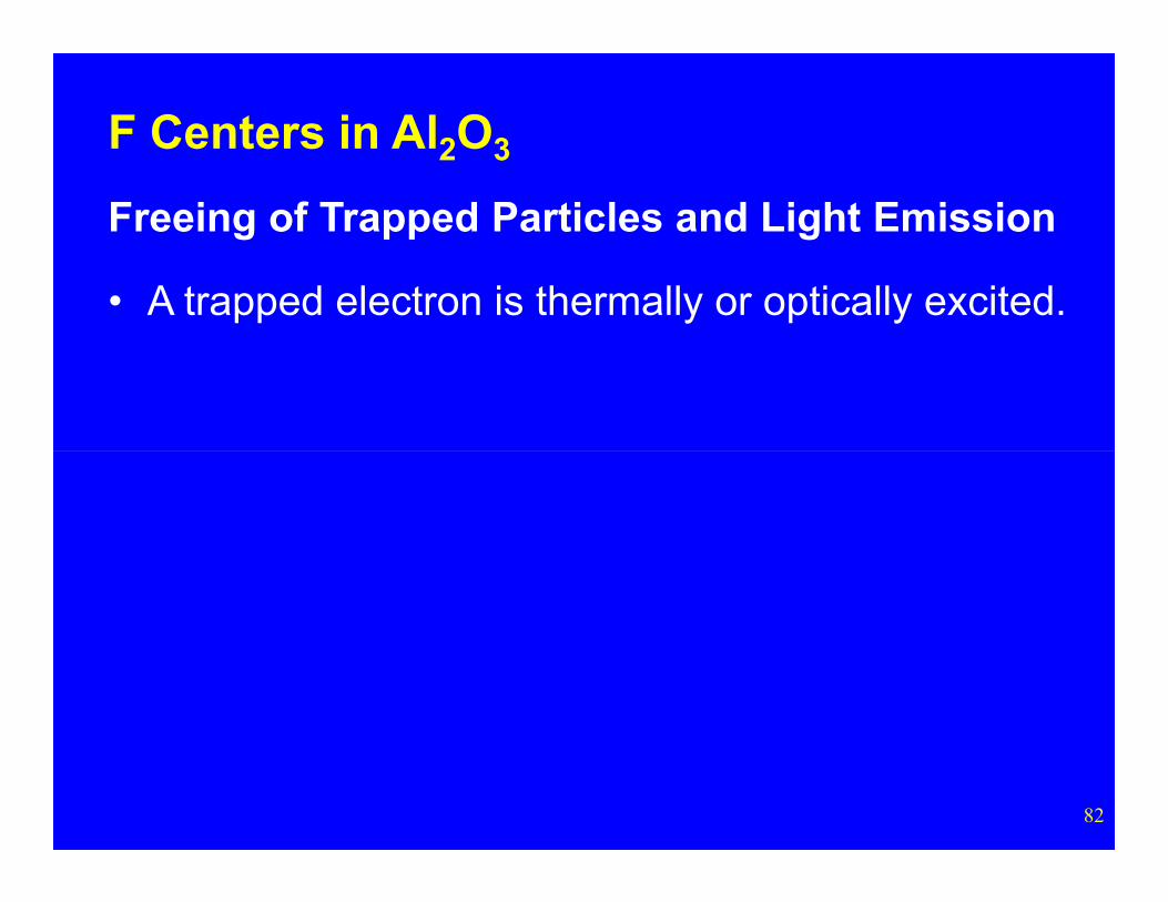
Freeing of Trapped Particles and Light Emission
• A trapped electron is thermally or optically excited.
82
CONDUCTION BAND
F+ center *e
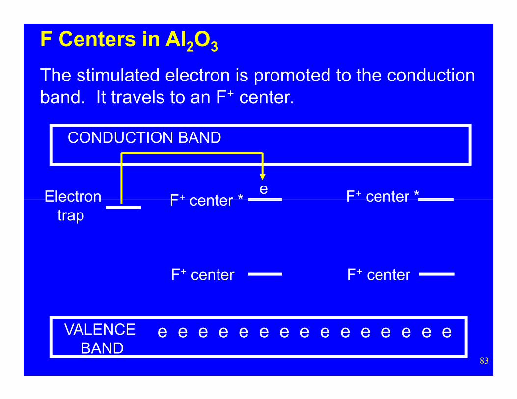
F Centers in Al2O3
The stimulated electron is promoted to the conduction band. It travels to an F+ center.
Electron F+ center *
83
VALENCE BAND
F+ center
F center
e e e e e e e e e e e e e e e
Electrontrap
F+ center
F center
CONDUCTION BAND
F+ center *e
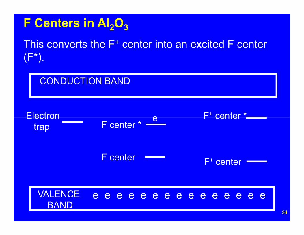
F Centers in Al2O3
This converts the F+ center into an excited F center (F*).
Electron
84
VALENCE BAND
F center
F center *
F+ center
F center
e e e e e e e e e e e e e e e
eElectrontrap
CONDUCTION BAND
F+ center *e
F Centers in Al2O3
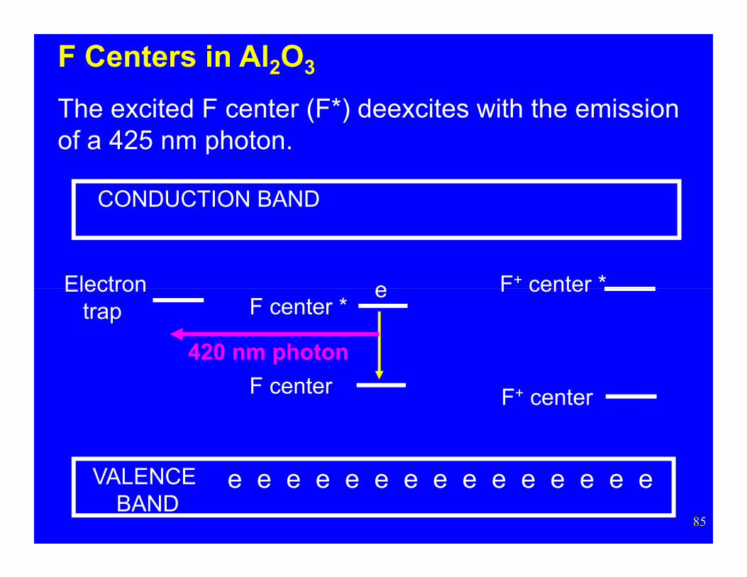
The excited F center (F*) deexcites with the emission of a 425 nm photon.
Electron
85
VALENCE BAND
F center
F center *
F+ center
F center
e e e e e e e e e e e e e e e
eElectrontrap
420 nm photon
CONDUCTION BAND
F+ center *
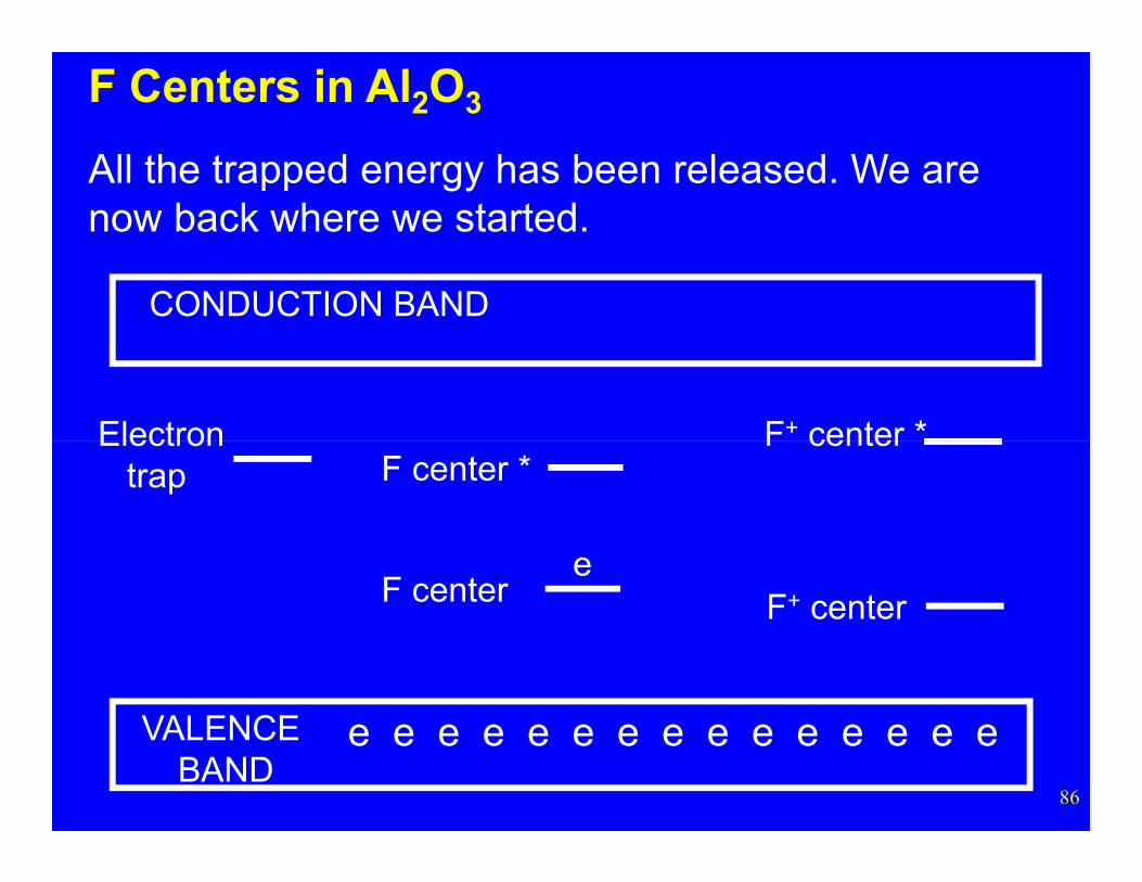
F Centers in Al2O3
All the trapped energy has been released. We are now back where we started.
Electron
86
VALENCE BAND
F center
F center *
F+ center
F center
e e e e e e e e e e e e e e e
e
Electrontrap