Embed Size (px)
Citation preview

07.10.2009, T. Tischler, CBM Collaboration Meeting, Split
Status MVD Demonstrator:System Integration
T.Tischler, S. Amar-Youcef, M. Deveaux, D. Doering, J. Heuser,
I. Fröhlich, J. Michel, C. Müntz, C.Schrader, S. Seddiki, J. Stroth, C. Trageser
and B. Wiedemann

07.10.2009, T. Tischler, CBM Collaboration Meeting, Split
Status MVD Demonstrator:Mechanics & Integration
Outline:
MVD DemonstratorDesignMaterial overviewMechanical supportBonding and DemoAux-Board
Demonstrator in the Lab
Demonstrator for the Beam test
Summary and Outlook
Demonstrator
Prototype
Final MVD
07.10.2009, T. Tischler, CBM Collaboration Meeting, Split
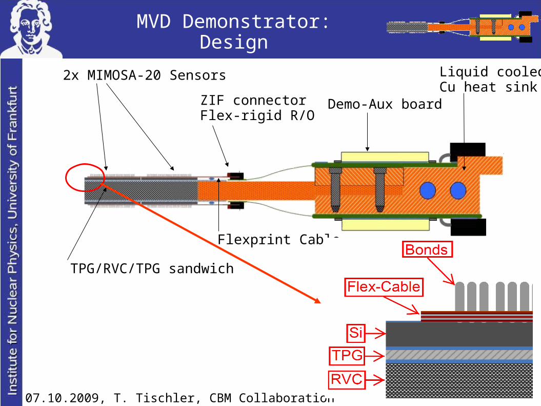
MVD Demonstrator:Design
2x MIMOSA-20 Sensors
ZIF connectorFlex-rigid R/O
Demo-Aux board
Liquid cooledCu heat sink
TPG/RVC/TPG sandwich
Flexprint Cable

07.10.2009, T. Tischler, CBM Collaboration Meeting, Split
MVD Demonstrator:Material overview
MIMOSA-20
- 320 x 640 pixels- 30 µm pixel pitch- 750 µm thickness- ~ 2 ms time resolution- ~ 2 cm² active surface- 2 serial analogue outputs- Differential output lines
FlexPrint Cable
- 36 µm copper in 3 layers- minimized set of lines for 2 MIMOSA-20- individiual readout for two sensors
with one cable- 60 pads for chip bonding- 0.21 % X
0

07.10.2009, T. Tischler, CBM Collaboration Meeting, Split
MVD Demonstrator:Mechanical support – setting up
Structure of the support:
TPG (Thermal Pyrolytic Graphite) ultra high heat conduction ( 1500 W/mK in two dimensions = 4x value of copper )
RVC (Reticulated Vitreous Carbon foam)
ultra light and stiff material
Thickness [μm]
1x Splicing tape glue 35 ± 52x TPG (C) 500 ± 102x Liquid glue 100 ± 201x RVC (C foam) 3000 ± 100
Sum 4235 ± 102
2x
Currently 0.6 % X0
plus sensors
TPG
TPG
RVC
Glue
Glue
Currently :schematic view:
Glue: 2-component Araldite 2011Huntsman

07.10.2009, T. Tischler, CBM Collaboration Meeting, Split
MVD Demonstrator:Mechanical support – setting up
Glueing TPG to RVC,TPG-RVC to TPG.
Accurate knowledge of thethickness and surfaceis needed.
Several thickness measurementswere accomplished.
Measurements were used toselect good samples for the support needed.

07.10.2009, T. Tischler, CBM Collaboration Meeting, Split
MVD Demonstrator:Mechanical support – setting up
Comparisons betweenTPG-RVC-TPGplate surface before and aftercutting out the “stripe”were done.
Cutting does not trigger relevanteffects on the surface in termsof damage or bending.
Cutted “stripes” ready for bendingand cooling tests as well as forintegration into experimentalsetup.
before cutting
after cutting
Area without chips
fittet radius15000 mm

07.10.2009, T. Tischler, CBM Collaboration Meeting, Split
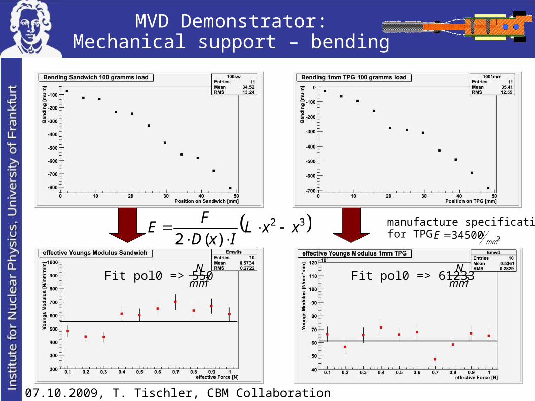
MVD Demonstrator:Mechanical support – bending
schematic view:
No load
??? g / kg
??? g / kg
Load range 10 – 100 gramms
Bending tests with the support (Sandwich) and 1mm TPG (for comparison) were arrangedto gain knowledge on the maximum load which can be handled by the supportwithout lasting damages.In addition a value for the Young Modulus was calculated based on measured data.
TPG gauge
F
07.10.2009, T. Tischler, CBM Collaboration Meeting, Split
MVD Demonstrator:Mechanical support – bending
manufacture specificationfor TPG
Fit pol0 => 550 Fit pol0 => 61233
32
)(2xxL
IxD
FE
2mm
N2mm
N
234500mm
NE
07.10.2009, T. Tischler, CBM Collaboration Meeting, Split
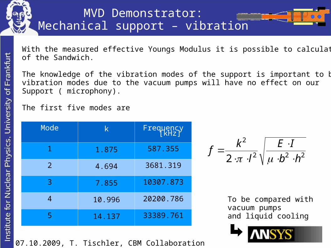
MVD Demonstrator:Mechanical support – vibration
With the measured effective Youngs Modulus it is possible to calculate the vibration modesof the Sandwich.
The knowledge of the vibration modes of the support is important to be sure that vibration modes due to the vacuum pumps will have no effect on ourSupport ( microphony).
The first five modes are
Mode k Frequency [kHz]
1 1.875 587.355
2 4.694 3681.319
3 7.855 10307.873
4 10.996 20200.786
5 14.137 33389.761
To be compared withvacuum pumpsand liquid cooling
222
2
2 hb
IE
l
kf
07.10.2009, T. Tischler, CBM Collaboration Meeting, Split
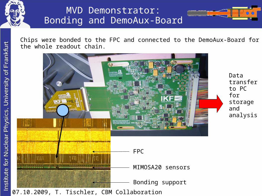
MVD Demonstrator:Bonding and DemoAux-Board
Chips were bonded to the FPC and connected to the DemoAux-Board for testingthe whole readout chain.
Datatransferto PCfor storageand analysis
Bonding support
MIMOSA20 sensors
FPC

07.10.2009, T. Tischler, CBM Collaboration Meeting, Split
MVD Demonstrator:in the Lab
Demonstrator in Lab ( in PVC-Box ) for first series of test mesurements.
Allowsreadout of maximal 2 MIMOSA20 senors through FPC and DemoAux-Boardreadout with a Fe55 sourcereadout with a running cooling systemsearch for the best calibration of the MIMOSA20 sensorstests related to the heat conductivity of the whole Demonstratortemperature monitoring
DemoAux FPC sensors
Sandwichcooling
schematic view:

07.10.2009, T. Tischler, CBM Collaboration Meeting, Split
sensorsglue TPGcopper
RVC
Cooling system
- 40 °C- 20 °C
glue
MVD Demonstrator:in the Lab
Cooling transport through the Demonstrator - 10,3 °C with running sensors- 12,6 °C without running sensors
Measured temperatures within the PVC-Box show no big differences on the TPGwith and without running sensors.
Nevertheless temperature transport between cooling system and the copper supportas well as between the TPG and the copper support has to be improved further.
All measurements in the PVC-Box were taken under normal pressure.
07.10.2009, T. Tischler, CBM Collaboration Meeting, Split
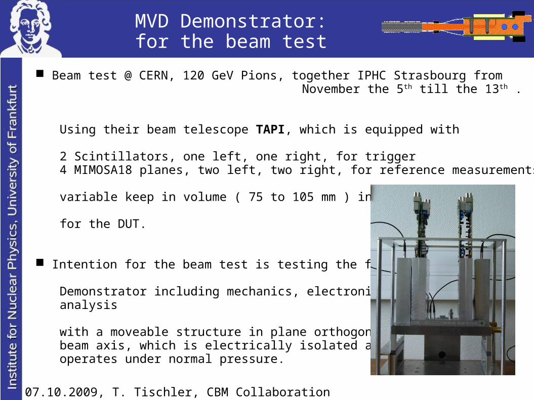
MVD Demonstrator:for the beam test
Beam test @ CERN, 120 GeV Pions, together IPHC Strasbourg fromNovember the 5th till the 13th .
Using their beam telescope TAPI, which is equipped with
2 Scintillators, one left, one right, for trigger4 MIMOSA18 planes, two left, two right, for reference measurements
variable keep in volume ( 75 to 105 mm ) in the middle
for the DUT.
Intention for the beam test is testing the full
Demonstrator including mechanics, electronics andanalysis
with a moveable structure in plane orthogonal to thebeam axis, which is electrically isolated andoperates under normal pressure.

07.10.2009, T. Tischler, CBM Collaboration Meeting, Split
MVD Demonstrator:for the beam test
Two mechanical setups are constructed,one with single sided readout for two MIMOSA20 sensorsone with double sided readout for four MIMOSA20 sensors
Assembled are two Aluminium frames for holding and cooling the Demonstrator.
In addtion two cases are build to minimize condensation and to open the possibility of N
2-flow.
Autodesk Inventor 10
Double sidedSingle sided

07.10.2009, T. Tischler, CBM Collaboration Meeting, Split
MVD Demonstrator:for the beam test
From the CAD-model to a real support structure for the beam test:

07.10.2009, T. Tischler, CBM Collaboration Meeting, Split
Summary and Outlook
Summary:
• Global design of the MVD Demonstrator adapted for the test in the Lab.
• Mechanical support was build and tested focused on materialcharacterisation and quality checks.
• Tests in the Lab under controlled environment show promising resultse.g. in respect to noise.
• Global design was changed due to given constrains for the beam test.
• For the upcoming beam test an one sided and a double sided versionwere constructed and build.
Outlook:
This phase: building the MVD Demonstrator will be concluded with a hopefullysuccessful beam test.
( Demonstrator++ versions under debate with improved support (CVD),different sensors, optimized FPC )