Embed Size (px)
Citation preview
1
Section 7: System ProtectionBill Brown, P.E., Square D Engineering Services
IntroductionAn important consideration in power system design is system protection. Without system protection, the powersystem itself, which is intended to be of benefit to the facility in question, would itself become a hazard.
The major concern for system protection is protection against the effects of destructive, abnormally high currents.These abnormal currents, if left unchecked, could cause fires or explosions resulting in risk to personnel anddamage to equipment. Other concerns, such as transient overvoltages, are also considered when designingpower system protection although they are generally considered only after protection against abnormal currentshas been designed.
Characterization of power system faultsAny current in excess of the rated current of equipment or the ampacity of a conductor may be considered anovercurrent. Overcurrents can generally be categorized as overloads or faults. An overload is a condition whereload equipment draws more current that the system can safely supply. The main hazard with overload conditionsis the thermal heating effects of overloaded equipment and conductors. Faults are unintentional connections of thepower system which result in overcurrents much larger in magnitude than overloads.
Faults can be categorized in several different ways. A fault with very little impedance in the unintended connectionis referred to as a short circuit or bolted fault (the latter term is used due to the fact that a short circuit can bethought of as a bus bar inadvertently bolted across two phase conductors or from phase to ground). A fault toground is referred to as a ground fault. A fault between all three phases is referred to as a 3 phase fault. A faultbetween two phases is referred to as a phase-to-phase fault. A fault which contains enough impedance in theunintentional connection to significantly affect the fault current vs. a true short circuit is known as an impedancefault. An arcing fault has the unintentional connection made via an electrical arc through an ionized gas such asair. All of these terms are used in practice to characterize the nature of a fault.
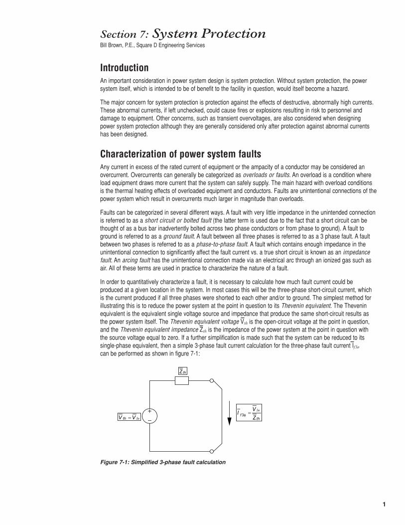
In order to quantitatively characterize a fault, it is necessary to calculate how much fault current could beproduced at a given location in the system. In most cases this will be the three-phase short-circuit current, whichis the current produced if all three phases were shorted to each other and/or to ground. The simplest method forillustrating this is to reduce the power system at the point in question to its Thevenin equivalent. The Theveninequivalent is the equivalent single voltage source and impedance that produce the same short-circuit results asthe power system itself. The Thevenin equivalent voltage Vth is the open-circuit voltage at the point in question, and the Thevenin equivalent impedance Zth is the impedance of the power system at the point in question withthe source voltage equal to zero. If a further simplification is made such that the system can be reduced to itssingle-phase equivalent, then a simple 3-phase fault current calculation for the three-phase fault current If3ø
can be performed as shown in figure 7-1:
Figure 7-1: Simplified 3-phase fault calculation
thZ
lnVV th = thf Z
VI ln=φ3
2
The Thevenin impedance for a power system at a given point in the system is referred to as the short-circuitimpedance. In the great majority of power systems the short-circuit impedance is predominately inductive,therefore one simplification that is often made is to treat the impedance purely as inductance. This has the effect of causing the fault current to lag the system line-to-neutral voltage by 90˚. If the system is an ungroundeddelta system the equivalent line-to-neutral voltage can be obtained by performing a delta-wye conversion of the source voltage.
The phase-to-phase fault value can be calculated from the three-phase fault value if it is remembered that theline-to-line voltage magnitude is equal to the line-to-neutral voltage magnitude multiplied by √3, and that there willbe twice the impedance in the circuit since the return path must be considered. These two facts, taken together,allow computation of the line-to-line fault current magnitude as:
(7-1)
This, however, is as far as this simplified analysis method will take us. In order to further characterize faultcurrents, a method for calculating unbalanced faults must be used. The universally-accepted method for this is a method known as the method of symmetrical components.
In the method of symmetrical components, unbalanced currents and voltages are broken into three distinctcomponents: positive sequence, negative sequence, and zero sequence.These sequence components can bethought of as independent sets of rotating balanced phasors. The positive sequence set rotates in the standard A-B-C phase rotation. The negative sequence set rotates in the negative or C-B-A phase rotation. In the zerosequence set all three phase components are in phase with one another. The positive, negative and zerosequence components can be further simplified by referring only to the A-phase phasor of each set; these arereferred to as V1 for the positive sequence set, V2 for the negative sequence set and V0 for the zero-sequenceset. For a given set of phase voltages Va, Vb and Vc, the sequence components are related to the phase voltagesas follows:
(7-2)
(7-3)
(7-4)
(7-5)
(7-6)
(7-7)
where
a = 1<120˚
The system may be separated into positive, negative, and zero-sequence networks depending upon the fault typeand the resulting sequence quantities then combined per (7-5), (7-6), and (7-7) to yield the phase values.
Modern short-circuit analysis is performed using the computer. Even large systems can be quickly analyzed via short-circuit analysis software. Even so, some heuristic benefit can be gained by knowing how the method of symmetrical components works. For example, certain protective relays are often set in terms of negative-sequence values and ground currents are often referred to as zero-sequence quantities in the literature.
Another factor that must be taken into account is the existence of DC quantities in fault currents. Because of the system inductance the current cannot change instantaneously, therefore upon initiation of a fault the systemmust go through a transient condition which bridges the gap between the faulted and unfaulted conditions. This transition involves DC currents. For a generic single-phase AC circuit with an open-circuit voltage
and a short-circuit impedance consisting of resistance R and inductance L, the fault
llfI −
2
3 3φfllf
II =−
( )cba VaVaVV 21
31
++=
( )cba VaVaVV ++= 22
31
( )cba VVVV ++=31
0
021 VVVV a ++=
0212 VVaVaV b ++=
022
1 VVaVaV c ++=
)sin()( θω += tVtv m
3
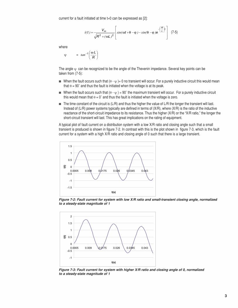
current for a fault initiated at time t=0 can be expressed as [2]:
(7-5)
where
ψ =
The angle ψ can be recognized to be the angle of the Thevenin impedance. Several key points can be taken from (7-5):
� When the fault occurs such that (θ - ψ )= 0 no transient will occur. For a purely inductive circuit this would meanthat θ = 90˚ and thus the fault is initiated when the voltage is at its peak.
� When the fault occurs such that (θ - ψ ) = 90˚ the maximum transient will occur. For a purely inductive circuitthis would mean that θ = 0˚ and thus the fault is initiated when the voltage is zero.
� The time constant of the circuit is (L/R) and thus the higher the value of L/R the longer the transient will last.Instead of (L/R) power systems typically are defined in terms of (X/R), where (X/R) is the ratio of the inductivereactance of the short-circuit impedance to its resistance. Thus the higher (X/R) or the “X/R ratio,” the longer theshort-circuit transient will last. This has great implications on the rating of equipment.
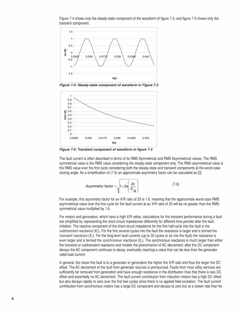
A typical plot of fault current on a distribution system with a low X/R ratio and closing angle such that a smalltransient is produced is shown in figure 7-2. In contrast with this is the plot shown in figure 7-3, which is the faultcurrent for a system with a high X/R ratio and closing angle of 0 such that there is a large transient.
⎥⎥
⎦
⎤
⎢⎢
⎣
⎡−−−+
+=
⎟⎠⎞
⎜⎝⎛− tLR
m etLR
Vti )sin()sin(
)()( ϕθϕθω
ω 22
⎟⎠
⎞⎜⎝
⎛−
RLω1tan
Figure 7-2: Fault current for system with low X/R ratio and small-transient closing angle, normalized to a steady-state magnitude of 1
-1.5
-1
-0.5
0
0.5
1
1.5
0.0005 0.009 0.0175 0.026 0.0345 0.043
t(s)
i(t)
Figure 7-3: Fault current for system with higher X/R ratio and closing angle of 0, normalized to a steady-state magnitude of 1
-1
-0.5
0
0.5
1
1.5
2
0.0005 0.009 0.0175 0.026 0.0345 0.043
t(s)
i(t)
4
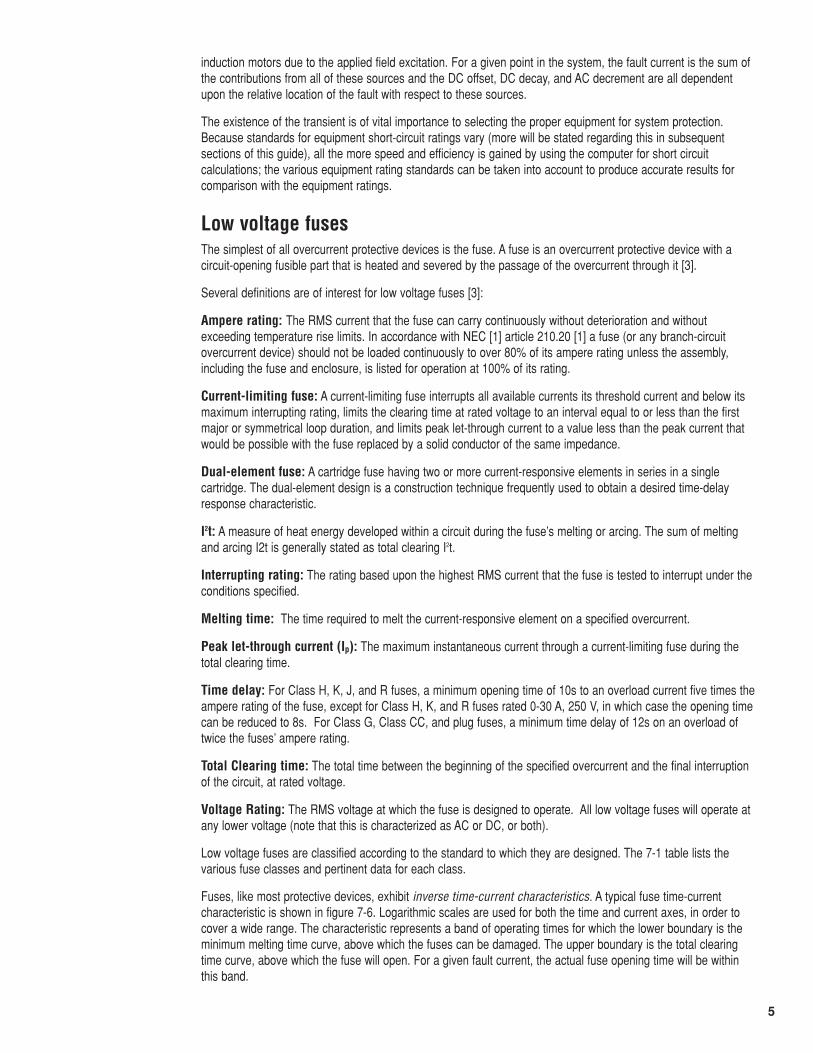
Figure 7-4 shows only the steady-state component of the waveform of figure 7-3, and figure 7-5 shows only thetransient component.
The fault current is often described in terms of its RMS Symmetrical and RMS Asymmetrical values. The RMSsymmetrical value is the RMS value considering the steady-state component only. The RMS asymmetrical value isthe RMS value over the first cycle considering both the steady-state and transient components at the worst-caseclosing angle. As a simplification of (7-5) an approximate asymmetry factor can be calculated as [3]
(7-9)
For example, this asymmetry factor for an X/R ratio of 25 is 1.6, meaning that the approximate worst-case RMSasymmetrical value over the first cycle for the fault current at an X/R ratio of 25 will be no greater than the RMSsymmetrical value multiplied by 1.6.
For motors and generators, which have a high X/R ratios, calculations for the transient performance during a faultare simplified by representing the short-circuit impedances differently for different time periods after the faultinitiation. The reactive component of the short-circuit impedance for the first half-cycle into the fault is thesubtransient reactance (X"d). For the first several cycles into the fault the reactance is larger and is termed thetransient reactance (X'd). For the long-term fault currents (up to 30 cycles or so into the fault) the reactance iseven larger and is termed the synchronous reactance (Xd). The synchronous reactance is much larger than eitherthe transient or subtransient reactance and models the phenomenon of AC decrement; after the DC componentdecays the AC component continues to decay, eventually reaching a value that can be less than the generatorrated load current.
In general, the closer the fault is to a generator or generators the higher the X/R ratio and thus the larger the DCoffset. The AC decrement of the fault from generator sources is pronounced. Faults from most utility services aresufficiently far removed from generation and have enough resistance in the distribution lines that there is less DCoffset and essentially no AC decrement. The fault current contribution from induction motors has a high DC offsetbut also decays rapidly to zero over the first few cycles since there is no applied field excitation. The fault currentcontribution from synchronous motors has a large DC component and decays to zero but at a slower rate than for
Figure 7-4: Steady-state component of waveform in Figure 7-3
-1.5
-1
-0.5
0
0.5
1
1.5
0.0005 0.009 0.0175 0.026 0.0345 0.043
t(s)
ss i(
t)
Figure 7-5: Transient component of waveform in figure 7-3
00.10.20.30.40.50.60.70.80.9
1
0.0005 0.009 0.0175 0.026 0.0345 0.043
t(s)
tran
i(t)
⎟⎟⎟
⎠
⎞
⎜⎜⎜
⎝
⎛+=
RX
efactorAsymmetry π221
5
induction motors due to the applied field excitation. For a given point in the system, the fault current is the sum ofthe contributions from all of these sources and the DC offset, DC decay, and AC decrement are all dependentupon the relative location of the fault with respect to these sources.
The existence of the transient is of vital importance to selecting the proper equipment for system protection.Because standards for equipment short-circuit ratings vary (more will be stated regarding this in subsequentsections of this guide), all the more speed and efficiency is gained by using the computer for short circuitcalculations; the various equipment rating standards can be taken into account to produce accurate results forcomparison with the equipment ratings.
Low voltage fusesThe simplest of all overcurrent protective devices is the fuse. A fuse is an overcurrent protective device with acircuit-opening fusible part that is heated and severed by the passage of the overcurrent through it [3].
Several definitions are of interest for low voltage fuses [3]:
Ampere rating: The RMS current that the fuse can carry continuously without deterioration and withoutexceeding temperature rise limits. In accordance with NEC [1] article 210.20 [1] a fuse (or any branch-circuitovercurrent device) should not be loaded continuously to over 80% of its ampere rating unless the assembly,including the fuse and enclosure, is listed for operation at 100% of its rating.
Current-limiting fuse: A current-limiting fuse interrupts all available currents its threshold current and below itsmaximum interrupting rating, limits the clearing time at rated voltage to an interval equal to or less than the firstmajor or symmetrical loop duration, and limits peak let-through current to a value less than the peak current thatwould be possible with the fuse replaced by a solid conductor of the same impedance.
Dual-element fuse: A cartridge fuse having two or more current-responsive elements in series in a singlecartridge. The dual-element design is a construction technique frequently used to obtain a desired time-delayresponse characteristic.
I2t: A measure of heat energy developed within a circuit during the fuse’s melting or arcing. The sum of meltingand arcing I2t is generally stated as total clearing I2t.
Interrupting rating: The rating based upon the highest RMS current that the fuse is tested to interrupt under theconditions specified.
Melting time: The time required to melt the current-responsive element on a specified overcurrent.
Peak let-through current (Ip): The maximum instantaneous current through a current-limiting fuse during thetotal clearing time.
Time delay: For Class H, K, J, and R fuses, a minimum opening time of 10s to an overload current five times theampere rating of the fuse, except for Class H, K, and R fuses rated 0-30 A, 250 V, in which case the opening timecan be reduced to 8s. For Class G, Class CC, and plug fuses, a minimum time delay of 12s on an overload oftwice the fuses’ ampere rating.
Total Clearing time: The total time between the beginning of the specified overcurrent and the final interruptionof the circuit, at rated voltage.
Voltage Rating: The RMS voltage at which the fuse is designed to operate. All low voltage fuses will operate atany lower voltage (note that this is characterized as AC or DC, or both).
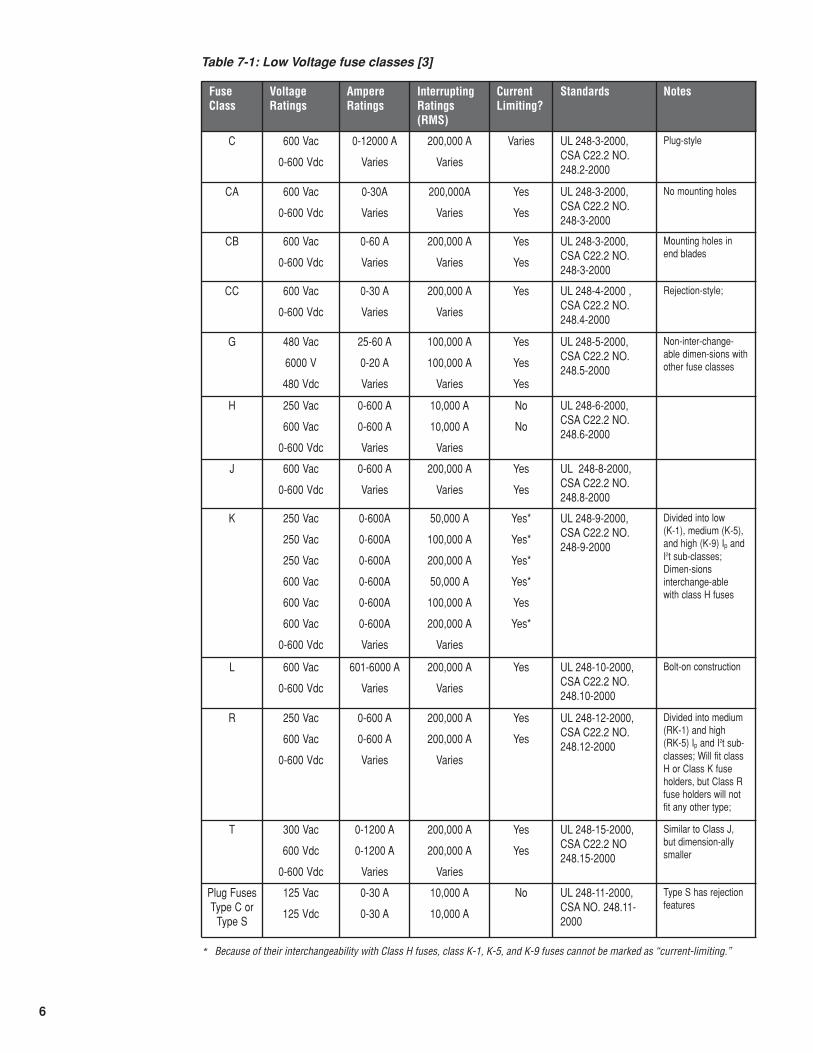
Low voltage fuses are classified according to the standard to which they are designed. The 7-1 table lists thevarious fuse classes and pertinent data for each class.
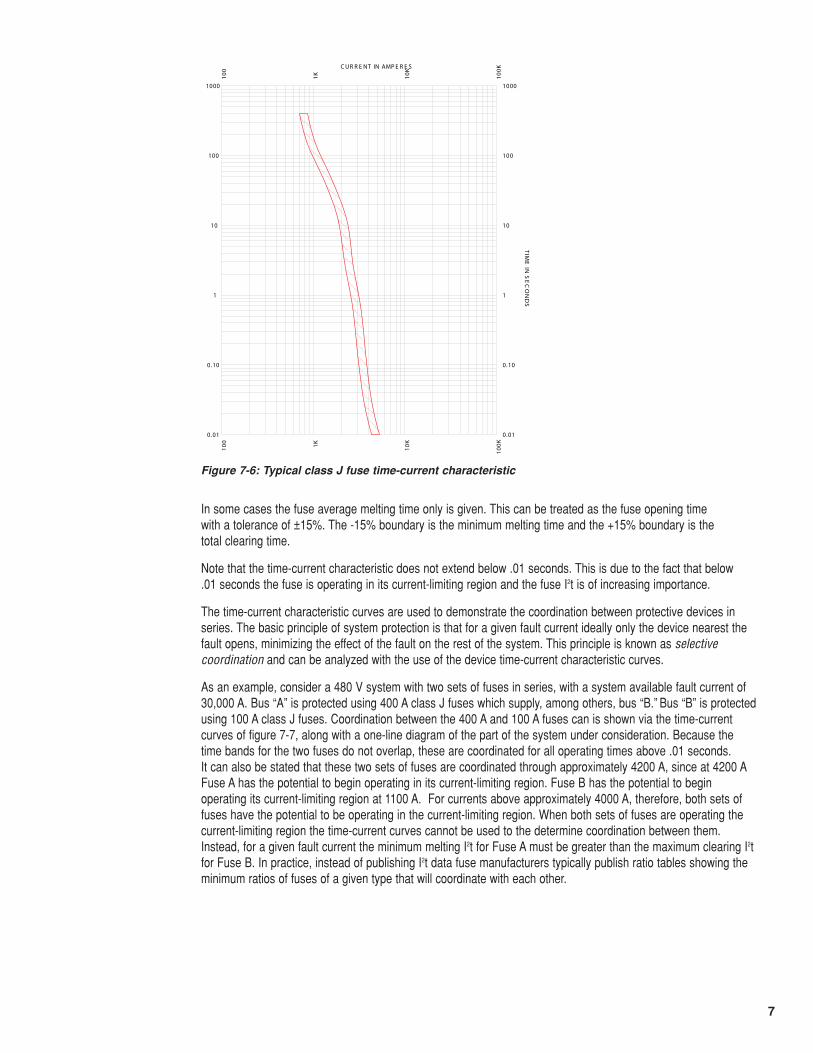
Fuses, like most protective devices, exhibit inverse time-current characteristics. A typical fuse time-currentcharacteristic is shown in figure 7-6. Logarithmic scales are used for both the time and current axes, in order tocover a wide range. The characteristic represents a band of operating times for which the lower boundary is theminimum melting time curve, above which the fuses can be damaged. The upper boundary is the total clearingtime curve, above which the fuse will open. For a given fault current, the actual fuse opening time will be withinthis band.
6
Table 7-1: Low Voltage fuse classes [3]
FuseClass
VoltageRatings
AmpereRatings
InterruptingRatings(RMS)
CurrentLimiting?
Standards Notes
C 600 Vac
0-600 Vdc
0-12000 A
Varies
200,000 A
Varies
Varies UL 248-3-2000,CSA C22.2 NO.248.2-2000
Plug-style
CA 600 Vac
0-600 Vdc
0-30A
Varies
200,000A
Varies
Yes
Yes
UL 248-3-2000,CSA C22.2 NO.248-3-2000
No mounting holes
CB 600 Vac
0-600 Vdc
0-60 A
Varies
200,000 A
Varies
Yes
Yes
UL 248-3-2000,CSA C22.2 NO.248-3-2000
Mounting holes inend blades
CC 600 Vac
0-600 Vdc
0-30 A
Varies
200,000 A
Varies
Yes UL 248-4-2000 ,CSA C22.2 NO.248.4-2000
Rejection-style;
G 480 Vac
6000 V
480 Vdc
25-60 A
0-20 A
Varies
100,000 A
100,000 A
Varies
Yes
Yes
Yes
UL 248-5-2000,CSA C22.2 NO.248.5-2000
Non-inter-change-able dimen-sions withother fuse classes
H 250 Vac
600 Vac
0-600 Vdc
0-600 A
0-600 A
Varies
10,000 A
10,000 A
Varies
No
No
UL 248-6-2000,CSA C22.2 NO.248.6-2000
J 600 Vac
0-600 Vdc
0-600 A
Varies
200,000 A
Varies
Yes
Yes
UL 248-8-2000,CSA C22.2 NO.248.8-2000
K 250 Vac
250 Vac
250 Vac
600 Vac
600 Vac
600 Vac
0-600 Vdc
0-600A
0-600A
0-600A
0-600A
0-600A
0-600A
Varies
50,000 A
100,000 A
200,000 A
50,000 A
100,000 A
200,000 A
Varies
Yes*
Yes*
Yes*
Yes*
Yes
Yes*
UL 248-9-2000,CSA C22.2 NO.248-9-2000
Divided into low (K-1), medium (K-5),and high (K-9) Ip andI2t sub-classes;Dimen-sionsinterchange-able with class H fuses
L 600 Vac
0-600 Vdc
601-6000 A
Varies
200,000 A
Varies
Yes UL 248-10-2000,CSA C22.2 NO.248.10-2000
Bolt-on construction
R 250 Vac
600 Vac
0-600 Vdc
0-600 A
0-600 A
Varies
200,000 A
200,000 A
Varies
Yes
Yes
UL 248-12-2000,CSA C22.2 NO.248.12-2000
Divided into medium(RK-1) and high (RK-5) Ip and I2t sub-classes; Will fit classH or Class K fuseholders, but Class Rfuse holders will notfit any other type;
T 300 Vac
600 Vdc
0-600 Vdc
0-1200 A
0-1200 A
Varies
200,000 A
200,000 A
Varies
Yes
Yes
UL 248-15-2000,CSA C22.2 NO248.15-2000
Similar to Class J,but dimension-allysmaller
Plug FusesType C or
Type S
125 Vac
125 Vdc
0-30 A
0-30 A
10,000 A
10,000 A
No UL 248-11-2000,CSA NO. 248.11-2000
Type S has rejectionfeatures
* Because of their interchangeability with Class H fuses, class K-1, K-5, and K-9 fuses cannot be marked as “current-limiting.”
7
In some cases the fuse average melting time only is given. This can be treated as the fuse opening time with a tolerance of ±15%. The -15% boundary is the minimum melting time and the +15% boundary is the total clearing time.
Note that the time-current characteristic does not extend below .01 seconds. This is due to the fact that below .01 seconds the fuse is operating in its current-limiting region and the fuse I2t is of increasing importance.
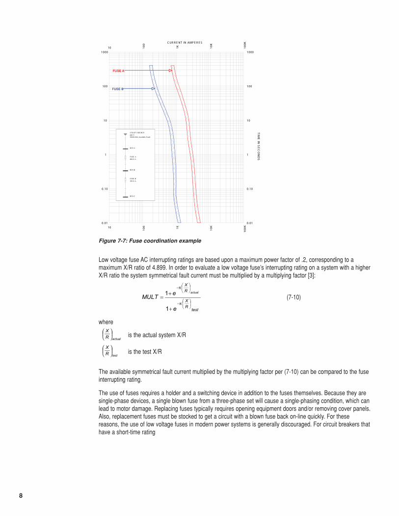
The time-current characteristic curves are used to demonstrate the coordination between protective devices inseries. The basic principle of system protection is that for a given fault current ideally only the device nearest thefault opens, minimizing the effect of the fault on the rest of the system. This principle is known as selectivecoordination and can be analyzed with the use of the device time-current characteristic curves.
As an example, consider a 480 V system with two sets of fuses in series, with a system available fault current of30,000 A. Bus “A” is protected using 400 A class J fuses which supply, among others, bus “B.” Bus “B” is protectedusing 100 A class J fuses. Coordination between the 400 A and 100 A fuses can is shown via the time-currentcurves of figure 7-7, along with a one-line diagram of the part of the system under consideration. Because thetime bands for the two fuses do not overlap, these are coordinated for all operating times above .01 seconds. It can also be stated that these two sets of fuses are coordinated through approximately 4200 A, since at 4200 AFuse A has the potential to begin operating in its current-limiting region. Fuse B has the potential to beginoperating its current-limiting region at 1100 A. For currents above approximately 4000 A, therefore, both sets offuses have the potential to be operating in the current-limiting region. When both sets of fuses are operating thecurrent-limiting region the time-current curves cannot be used to the determine coordination between them.Instead, for a given fault current the minimum melting I2t for Fuse A must be greater than the maximum clearing I2tfor Fuse B. In practice, instead of publishing I2t data fuse manufacturers typically publish ratio tables showing theminimum ratios of fuses of a given type that will coordinate with each other.
Figure 7-6: Typical class J fuse time-current characteristic
100
100
1K1K
10K
10K
100K
100K
0 .01 0.01
0.10 0.10
1 1
10 10
100 100
1000 1000
C UR R E NT IN AMP E R E S
TIM
E IN
SE
CO
ND
S
8
Low voltage fuse AC interrupting ratings are based upon a maximum power factor of .2, corresponding to amaximum X/R ratio of 4.899. In order to evaluate a low voltage fuse’s interrupting rating on a system with a higherX/R ratio the system symmetrical fault current must be multiplied by a multiplying factor [3]:
(7-10)
where
is the actual system X/R
is the test X/R
The available symmetrical fault current multiplied by the multiplying factor per (7-10) can be compared to the fuseinterrupting rating.
The use of fuses requires a holder and a switching device in addition to the fuses themselves. Because they aresingle-phase devices, a single blown fuse from a three-phase set will cause a single-phasing condition, which canlead to motor damage. Replacing fuses typically requires opening equipment doors and/or removing cover panels.Also, replacement fuses must be stocked to get a circuit with a blown fuse back on-line quickly. For thesereasons, the use of low voltage fuses in modern power systems is generally discouraged. For circuit breakers thathave a short-time rating
Figure 7-7: Fuse coordination example
10
10
100
100
1K1K
10K
10K
100K
100K
0 .01 0.01
0.10 0.10
1 1
10 10
100 100
1000 1000
C UR R E NT IN AMP E R E S
TIM
E IN
SE
CO
ND
S
FUSE A
FUSE B
FUSE A
FUSE B
UTILITY SOURCE480 V30000.00A Available Fault
BUS A
FUSE A400.0 A
BUS B
FUSE B100.0 A
BUS C
testRX
RX
e
eMULTactual
⎟⎠⎞
⎜⎝⎛−
⎟⎠⎞
⎜⎝⎛−
+
+=
π
π
1
1
actualRX
⎟⎠⎞
⎜⎝⎛
testRX
⎟⎠⎞
⎜⎝⎛
9
Low voltage molded-case circuit breakersThe molded-case circuit breaker is the “workhorse” for system protection 600V and below. A circuit breaker is adevice designed to open and close by nonautomatic means and to open the circuit automatically on apredetermined overcurrent without damage to itself when properly applied within its rating [1].
The following terms apply to molded-case circuit breakers [3], [4]:
Voltage: Circuit breakers are designed and marked with the maximum voltage at which they can be applied.Circuit breaker voltage ratings distinguish between delta-connected, 3-wire systems and wye-connected, 4-wiresystems. As stated in NEC article 240.85 [1], a circuit breaker with a straight voltage rating, such as 240 or 480 Vcan be used in a circuit in which the nominal voltage between any two conductors does not exceed the circuitbreaker’s voltage rating. Breakers with slash ratings, such as 120/240 V or 480 Y/277 V, can be applied in asolidly-grounded circuit where the nominal voltage of any conductor to ground does not exceed the lower of thetwo values of the circuit breaker’s voltage rating and the nominal voltage between any two conductors does notexceed the higher value of the circuit breaker’s voltage rating.
Frequency: Molded-case circuit breakers are normally suitable for 50Hz or 60Hz. Some have DC ratings as well.
Continuous current or Rated current: This is the maximum current a circuit breaker can carry continuously at a given ambient temperature rating without tripping (typically 40˚C). In accordance with NEC [1] article 210.20 a circuit breaker (or any branch circuit overcurrent device) should not be loaded to over 80% of its continuouscurrent unless the assembly, including the circuit breaker and enclosure, is listed for operation at 100% of its rating.
Poles: The number of poles is the number of ganged circuit breaker elements in a single housing. Circuitbreakers are available with one, two, or three poles, and also four poles for certain applications. Per NEC [1]article 240.85 a two-pole circuit breaker cannot be used for protecting a 3-phase, corner-grounded delta circuitunless the circuit breaker is marked 1ø - 3ø to indicate such suitability.
Control voltage: The control voltage rating is the AC or DC voltage designated to be applied to control devices intended to open or close a circuit breaker. In most cases this only applies to accessories that arecustom-ordered, such as motor operators.
Interrupting rating: This is the highest current at rated voltage that the circuit breaker is intended to interruptunder standard test conditions.
Short-time or Withstand Rating: This characterizes the circuit-breaker’s ability to withstand the effects of short-circuit current flow for a stated period. Molded-case circuit breakers typically do not have a withstand rating,although some newer-design breakers do.
Instantaneous override: A function of an electronic trip circuit breaker that causes the instantaneous function tooperate above a given level of current if the instantaneous function characteristic has been disabled.
Current Limiting Circuit Breaker: This is a circuit breaker which does not employ a fusible element and, whenoperating in its current-limiting range, limits the let-through I2t to a value less than the I2t of a _-cycle wave of thesymmetrical prospective current.
HID: This is a marking that indicates that a circuit breaker has passed additional endurance and temperature risetests to assess its ability to be used as the regular switching device for high intensity discharge lighting. Per NEC240.80 (D) a circuit breaker which is used as a switch in an HID lighting circuit must be marked as HID. HIDcircuit breakers can also be used as switches in fluorescent lighting circuits.
SWD: This is a marking that indicates that a circuit breaker has passed additional endurance and temperaturerise tests to assess its ability to be used as the regular switching device fluorescent lighting. Per NEC 240.80 (D)a circuit breaker which is used as a switch in an HID lighting circuit must be marked as SWD or HID.
Frame: The term Frame is applied to a group of circuit breakers of similar configuration. Frame size is expressedin amperes and corresponds to the largest ampere rating available in that group.
10
Thermal-magnetic circuit breaker: This type of circuit breaker contains a thermal element to trip the circuitbreaker for overloads and a faster magnetic instantaneous element to trip the circuit breaker for short circuits. On many larger thermal-magnetic circuit breakers the instantaneous element is adjustable.
Electronic trip circuit breaker: An electronic circuit breaker contains a solid-state adjustable trip unit. Thesecircuit breakers are extremely flexible in coordination with other devices.
Sensor: An electronic-trip circuit breaker’s sensor is usually an air-core current transformer (CT) designedspecifically to work with that circuit breaker’s trip unit. The sensor size, in conjunction with the rating plug,determines the electronic-trip circuit breaker’s continuous current rating.
Rating plug: An electronic trip circuit breaker’s rating plug can vary the circuit breaker’s continuous current ratingas a function of it’s sensor size.
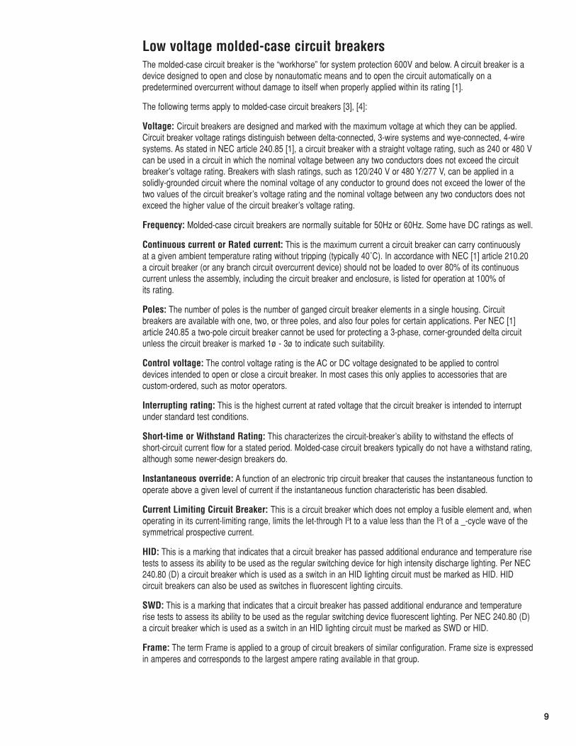
Typical molded-case circuit breakers are shown in figure 7-8. In figure 7-8 on the left is a thermal-magnetic circuitbreaker, and on the right is an electronic-trip circuit breaker. The thermal-magnetic circuit breaker is designed forcable connections and the electronic circuit breaker is designed for bus connections, but neither type is inherentlysuited for one connection type over another. Note the prominently-mounted operating handle on each circuitbreaker.
Circuit breakers may be mounted in stand-alone enclosures, in switchboards, or in panelboards (more informationon switchboards and panelboards is given in a later section of this guide).
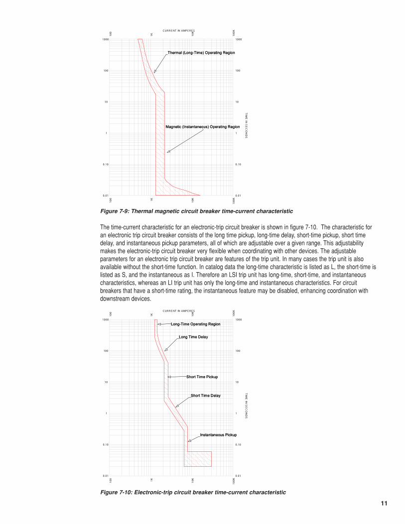
A typical thermal-magnetic circuit breaker time-current characteristic is shown in figure 7-9. Note the two distinctparts of the characteristic curve: The thermal or long-time characteristic is used for overload protection and themagnetic or instantaneous characteristic is used for short-circuit protection. Note also that there is a band ofoperating times for a given fault current. The lower boundary represents the lowest possible trip time and theupper boundary represents the highest possible trip time for a given current.
Figure 7-8: Molded-Case circuit breakers
11
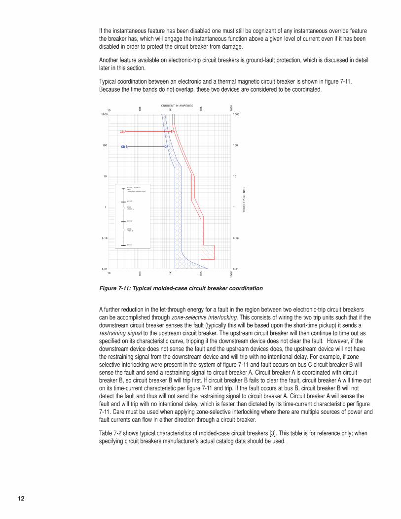
The time-current characteristic for an electronic-trip circuit breaker is shown in figure 7-10. The characteristic foran electronic trip circuit breaker consists of the long time pickup, long-time delay, short-time pickup, short timedelay, and instantaneous pickup parameters, all of which are adjustable over a given range. This adjustabilitymakes the electronic-trip circuit breaker very flexible when coordinating with other devices. The adjustableparameters for an electronic trip circuit breaker are features of the trip unit. In many cases the trip unit is alsoavailable without the short-time function. In catalog data the long-time characteristic is listed as L, the short-time islisted as S, and the instantaneous as I. Therefore an LSI trip unit has long-time, short-time, and instantaneouscharacteristics, whereas an LI trip unit has only the long-time and instantaneous characteristics. For circuitbreakers that have a short-time rating, the instantaneous feature may be disabled, enhancing coordination withdownstream devices.
100
100
1K1K
10K
10K
100K
100K
0 .01 0.01
0.10 0.10
1 1
10 10
100 100
1000 1000
C UR R E NT IN AMP E R E S
TIM
E IN
SE
CO
ND
S
Thermal (Long-Time) Operating Region
Magnetic (Instantaneous) Operating Region
Thermal (Long-Time) Operating Region
Magnetic (Instantaneous) Operating Region
Figure 7-9: Thermal magnetic circuit breaker time-current characteristic
100
100
1K1K
10K
10K
100K
100K
0 .01 0.01
0.10 0.10
1 1
10 10
100 100
1000 1000
C UR R E NT IN AMP E R E S
TIM
E IN
SE
CO
ND
S
Long-Time Operating Region
Long Time Delay
Short Time Pickup
Short Time Delay
Instantaneous Pickup
Long-Time Operating Region
Long Time Delay
Short Time Pickup
Short Time Delay
Instantaneous Pickup
Figure 7-10: Electronic-trip circuit breaker time-current characteristic
12
If the instantaneous feature has been disabled one must still be cognizant of any instantaneous override featurethe breaker has, which will engage the instantaneous function above a given level of current even if it has beendisabled in order to protect the circuit breaker from damage.
Another feature available on electronic-trip circuit breakers is ground-fault protection, which is discussed in detaillater in this section.
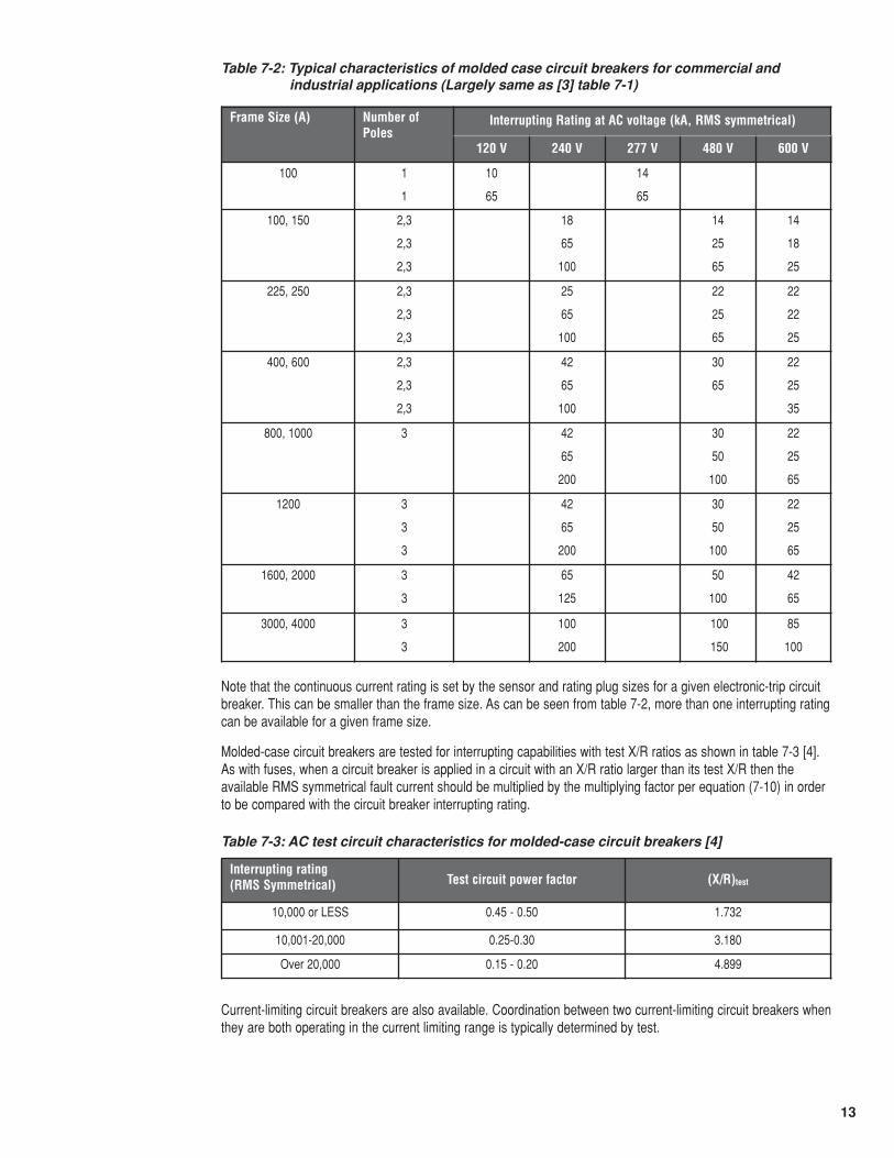
Typical coordination between an electronic and a thermal magnetic circuit breaker is shown in figure 7-11.Because the time bands do not overlap, these two devices are considered to be coordinated.
10
10
100
100
1K1K
10K
10K
100K
100K
0 .01 0.01
0.10 0.10
1 1
10 10
100 100
1000 1000
C UR R E NT IN AMP E R E S
TIM
E IN
SE
CO
ND
S
CB A
CB B
CB A
CB B
UTILITY SOURCE480 V30000.00A Available Fault
BUS A
BUS B
BUS C
CB A2500.0 A
CB B400.0 A
Figure 7-11: Typical molded-case circuit breaker coordination
A further reduction in the let-through energy for a fault in the region between two electronic-trip circuit breakerscan be accomplished through zone-selective interlocking. This consists of wiring the two trip units such that if thedownstream circuit breaker senses the fault (typically this will be based upon the short-time pickup) it sends arestraining signal to the upstream circuit breaker. The upstream circuit breaker will then continue to time out asspecified on its characteristic curve, tripping if the downstream device does not clear the fault. However, if thedownstream device does not sense the fault and the upstream devices does, the upstream device will not havethe restraining signal from the downstream device and will trip with no intentional delay. For example, if zoneselective interlocking were present in the system of figure 7-11 and fault occurs on bus C circuit breaker B willsense the fault and send a restraining signal to circuit breaker A. Circuit breaker A is coordinated with circuitbreaker B, so circuit breaker B will trip first. If circuit breaker B fails to clear the fault, circuit breaker A will time outon its time-current characteristic per figure 7-11 and trip. If the fault occurs at bus B, circuit breaker B will notdetect the fault and thus will not send the restraining signal to circuit breaker A. Circuit breaker A will sense thefault and will trip with no intentional delay, which is faster than dictated by its time-current characteristic per figure7-11. Care must be used when applying zone-selective interlocking where there are multiple sources of power andfault currents can flow in either direction through a circuit breaker.
Table 7-2 shows typical characteristics of molded-case circuit breakers [3]. This table is for reference only; whenspecifying circuit breakers manufacturer’s actual catalog data should be used.
13
Table 7-2: Typical characteristics of molded case circuit breakers for commercial andindustrial applications (Largely same as [3] table 7-1)
Note that the continuous current rating is set by the sensor and rating plug sizes for a given electronic-trip circuitbreaker. This can be smaller than the frame size. As can be seen from table 7-2, more than one interrupting ratingcan be available for a given frame size.
Molded-case circuit breakers are tested for interrupting capabilities with test X/R ratios as shown in table 7-3 [4].As with fuses, when a circuit breaker is applied in a circuit with an X/R ratio larger than its test X/R then theavailable RMS symmetrical fault current should be multiplied by the multiplying factor per equation (7-10) in orderto be compared with the circuit breaker interrupting rating.
Table 7-3: AC test circuit characteristics for molded-case circuit breakers [4]
Current-limiting circuit breakers are also available. Coordination between two current-limiting circuit breakers whenthey are both operating in the current limiting range is typically determined by test.
Frame Size (A) Number ofPoles
Interrupting Rating at AC voltage (kA, RMS symmetrical)
120 V 240 V 277 V 480 V 600 V
100 1
1
10
65
14
65
100, 150 2,3
2,3
2,3
18
65
100
14
25
65
14
18
25
225, 250 2,3
2,3
2,3
25
65
100
22
25
65
22
22
25
400, 600 2,3
2,3
2,3
42
65
100
30
65
22
25
35
800, 1000 3 42
65
200
30
50
100
22
25
65
1200 3
3
3
42
65
200
30
50
100
22
25
65
1600, 2000 3
3
65
125
50
100
42
65
3000, 4000 3
3
100
200
100
150
85
100
Interrupting rating (RMS Symmetrical) Test circuit power factor (X/R)test
10,000 or LESS 0.45 - 0.50 1.732
10,001-20,000 0.25-0.30 3.180
Over 20,000 0.15 - 0.20 4.899
14
By definition, low voltage molded case circuit breakers are not maintainable devices. Failure of a componentgenerally requires replacement of the entire circuit breaker unless the circuit breaker has been specificallydesigned for maintainability.
Magnetic-only circuit breakers which have only magnetic tripping capability are available. These are often usedas short-circuit protection for motor circuits (discussed in more detail in a later section of this guide). For thisreason these are often referred to as motor circuit protectors.
Molded case switches are also available. These do not have a thermal element, however most have a magneticelement which opens the switch above a specified current to protect the switch from damage due to lack of ashort-time rating.
Molded-case circuit breakers are available with several different options, such as stored-energy mechanisms, keyinterlocks, motor operators, etc. Refer to specific manufacturer’s literature for details.
Because the switching means is included with the device, molded-case circuit breakers give inherent flexibility ofoperation. This allows circuits to be reclosed without removing cover panels and exposing the operator tohazardous voltages. For three-phase circuits three-pole circuit breakers are used, which alleviates single-phasingconcerns. And, circuit breakers are not one-time devices, eliminating need to store spares in the event of a fault.These characteristics make molded-case circuit breakers very versatile protective devices.
Low voltage power circuit breakersFor larger systems, those devices closest to the source of power often require the ability to coordinate withmultiple levels of coordinating devices. In the case of circuit breakers, this generally requires a short-time rating as described in “Low voltage molded-case circuit breakers” section above. In addition, in this type ofapplication maintainability is desired due to the cost of a single circuit breaker. Low voltage power circuit breakers fill these needs.
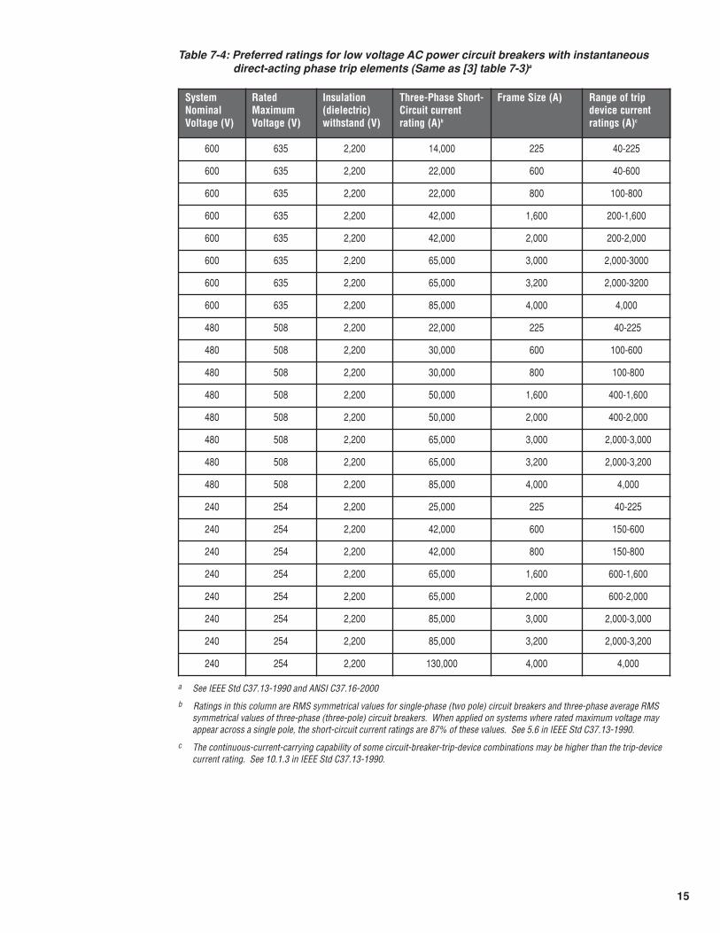
AC low voltage power circuit breakers are designed and manufactured per ANSI/IEEE Standard C37.13-1990 and UL 1066-1997. These are generally electronic-trip circuit breakers, although in existing installations olderdashpot-operated units may be encountered. The tripping characteristics are essentially identical to those forelectronic-trip molded-case circuit breakers, per figure 7-9, except that the instantaneous function may be disabled in all cases, unlike that of a molded-case circuit breaker. Tables 7-4 and 7-5 give the preferred ratings for low voltage AC power circuit breakers [3]. In addition, fused power circuit breakers are also available withhigher interrupting ratings, although many modern-design power circuit breakers do not require fuses to obtainshort-circuit ratings up to 200kA RMS symmetrical.
The short-time rating is an important characteristic of the low voltage power circuit breaker. The rated timeduration of the short-time rating is _ s (two periods of _-s current separated by a 15s interval of zero current) [5].Because of this short-time rating, low voltage power circuit breakers are also suitable for protective relayingapplications, as described below. Therefore, if a low voltage power circuit breaker is not equipped with a direct-acting trip unit it should not be subjected to more than _ s trip delay time at its short-time rating [5].
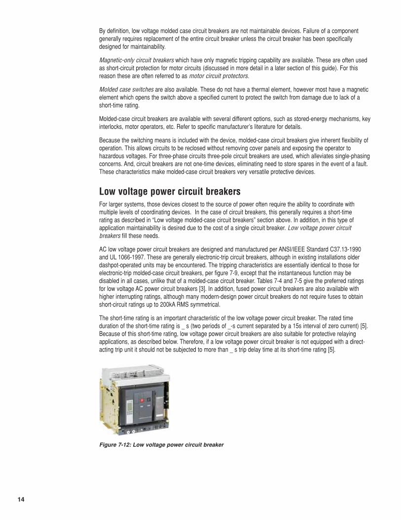
Figure 7-12: Low voltage power circuit breaker
15
Table 7-4: Preferred ratings for low voltage AC power circuit breakers with instantaneousdirect-acting phase trip elements (Same as [3] table 7-3)a
SystemNominalVoltage (V)
RatedMaximumVoltage (V)
Insulation(dielectric)withstand (V)
Three-Phase Short-Circuit currentrating (A)b
Frame Size (A) Range of tripdevice currentratings (A)c
600 635 2,200 14,000 225 40-225
600 635 2,200 22,000 600 40-600
600 635 2,200 22,000 800 100-800
600 635 2,200 42,000 1,600 200-1,600
600 635 2,200 42,000 2,000 200-2,000
600 635 2,200 65,000 3,000 2,000-3000
600 635 2,200 65,000 3,200 2,000-3200
600 635 2,200 85,000 4,000 4,000
480 508 2,200 22,000 225 40-225
480 508 2,200 30,000 600 100-600
480 508 2,200 30,000 800 100-800
480 508 2,200 50,000 1,600 400-1,600
480 508 2,200 50,000 2,000 400-2,000
480 508 2,200 65,000 3,000 2,000-3,000
480 508 2,200 65,000 3,200 2,000-3,200
480 508 2,200 85,000 4,000 4,000
240 254 2,200 25,000 225 40-225
240 254 2,200 42,000 600 150-600
240 254 2,200 42,000 800 150-800
240 254 2,200 65,000 1,600 600-1,600
240 254 2,200 65,000 2,000 600-2,000
240 254 2,200 85,000 3,000 2,000-3,000
240 254 2,200 85,000 3,200 2,000-3,200
240 254 2,200 130,000 4,000 4,000
a See IEEE Std C37.13-1990 and ANSI C37.16-2000
b Ratings in this column are RMS symmetrical values for single-phase (two pole) circuit breakers and three-phase average RMSsymmetrical values of three-phase (three-pole) circuit breakers. When applied on systems where rated maximum voltage mayappear across a single pole, the short-circuit current ratings are 87% of these values. See 5.6 in IEEE Std C37.13-1990.
c The continuous-current-carrying capability of some circuit-breaker-trip-device combinations may be higher than the trip-devicecurrent rating. See 10.1.3 in IEEE Std C37.13-1990.
16
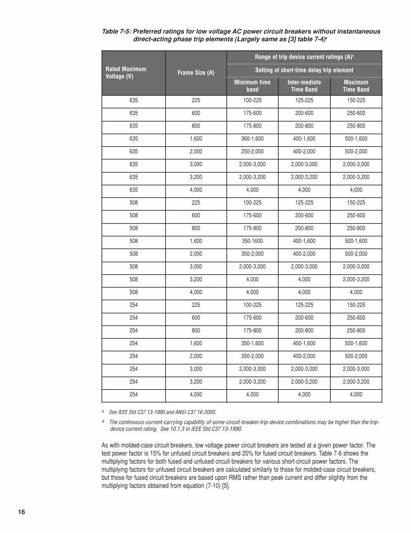
Table 7-5: Preferred ratings for low voltage AC power circuit breakers without instantaneousdirect-acting phase trip elements (Largely same as [3] table 7-4)a
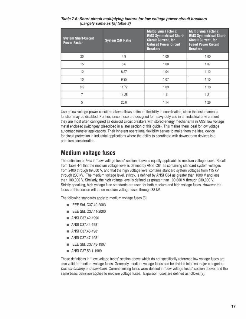
As with molded-case circuit breakers, low voltage power circuit breakers are tested at a given power factor. Thetest power factor is 15% for unfused circuit breakers and 20% for fused circuit breakers. Table 7-6 shows themultiplying factors for both fused and unfused circuit breakers for various short-circuit power factors. Themultiplying factors for unfused circuit breakers are calculated similarly to those for molded-case circuit breakers,but those for fused circuit breakers are based upon RMS rather than peak current and differ slightly from themultiplying factors obtained from equation (7-10) [5].
Rated MaximumVoltage (V) Frame Size (A)
Range of trip device current ratings (A)d
Setting of short-time delay trip element
Minimum timeband
Inter-mediateTime Band
MaximumTime Band
635 225 100-225 125-225 150-225
635 600 175-600 200-600 250-600
635 800 175-800 200-800 250-800
635 1,600 360-1,600 400-1,600 500-1,600
635 2,000 250-2,000 400-2,000 500-2,000
635 3,000 2,000-3,000 2,000-3,000 2,000-3,000
635 3,200 2,000-3,200 2,000-3,200 2,000-3,200
635 4,000 4,000 4,000 4,000
508 225 100-225 125-225 150-225
508 600 175-600 200-600 250-600
508 800 175-800 200-800 250-800
508 1,600 350-1600 400-1,600 500-1,600
508 2,000 350-2,000 400-2,000 500-2,000
508 3,000 2,000-3,000 2,000-3,000 2,000-3,000
508 3,200 4,000 4,000 2,000-3,200
508 4,000 4,000 4,000 4,000
254 225 100-225 125-225 150-225
254 600 175-600 200-600 250-600
254 800 175-800 200-800 250-800
254 1,600 350-1,600 400-1,600 500-1,600
254 2,000 350-2,000 400-2,000 500-2,000
254 3,000 2,000-3,000 2,000-3,000 2,000-3,000
254 3,200 2,000-3,200 2,000-3,200 2,000-3,200
254 4,000 4,000 4,000 4,000
a See IEEE Std C37.13-1990 and ANSI C37.16-2000.
d The continuous-current-carrying capability of some circuit-breaker-trip-device combinations may be higher than the trip-device current rating. See 10.1.3 in IEEE Std C37.13-1990.
17
Table 7-6: Short-circuit multiplying factors for low voltage power circuit breakers (Largely same as [5] table 3)
Use of low voltage power circuit breakers allows optimum flexibility in coordination, since the instantaneousfunction may be disabled. Further, since these are designed for heavy-duty use in an industrial environment they are most often configured as drawout circuit breakers with stored-energy mechanisms in ANSI low voltagemetal enclosed switchgear (described in a later section of this guide). This makes them ideal for low voltageautomatic transfer applications. Their inherent operational flexibility serves to make them the ideal device for circuit protection in industrial applications where the ability to coordinate with downstream devices is apremium consideration.
Medium voltage fusesThe definition of fuse in “Low voltage fuses” section above is equally applicable to medium voltage fuses. Recallfrom Table 4-1 that the medium voltage level is defined by ANSI C84 as containing standard system voltages from 2400 through 69,000 V, and that the high voltage level contains standard system voltages from 115 kVthrough 230 kV. The medium voltage level, strictly, is defined by ANSI C84 as greater than 1000 V and less than 100,000 V. Similarly, the high voltage level is defined as greater than 100,000 V through 230,000 V. Strictly-speaking, high voltage fuse standards are used for both medium and high voltage fuses. However thefocus of this section will be on medium voltage fuses through 38 kV.
The following standards apply to medium voltage fuses [3]:
� IEEE Std. C37.40-2003
� IEEE Std. C37.41-2000
� ANSI C37.42-1996
� ANSI C37.44-1981
� ANSI C37.46-1981
� ANSI C37.47-1981
� IEEE Std. C37.48-1997
� ANSI C37.53.1-1989
Those definitions in “Low voltage fuses” section above which do not specifically reference low voltage fuses arealso valid for medium voltage fuses. Generally, medium voltage fuses can be divided into two major categories:Current-limiting and expulsion. Current-limiting fuses were defined in “Low voltage fuses” section above, and thesame basic definition applies to medium voltage fuses. Expulsion fuses are defined as follows [3]:
System Short-CircuitPower Factor System X/R Ratio
Multiplying Factor xRMS Symmetrical Short-Circuit Current, forUnfused Power CircuitBreakers
Multiplying Factor xRMS Symmetrical Short-Circuit Current, forFused Power CircuitBreakers
20 4.9 1.00 1.00
15 6.6 1.00 1.07
12 8.27 1.04 1.12
10 9.95 1.07 1.15
8.5 11.72 1.09 1.18
7 14.25 1.11 1.21
5 20.0 1.14 1.26
18
Expulsion fuse: A vented fuse in which the expulsion effect of the gases produced by internal arcing, eitheralone or aided by other mechanisms, results in current interruption.
In addition, medium voltage fuses are further classified as power fuses or distribution fuses as follows [3]:
Power fuse: Defined by ANSI C37.42-1996 as having dielectric withstand (BIL) strengths at power levels, appliedprimarily in stations and substations, with mechanical construction basically adapted to station and substationmountings.
Distribution fuse: Defined by ANSI C37.42-1996 as having dielectric withstand (BIL) strengths at distributionlevels, applied primarily on distribution feeders and circuits, and with operating voltage limits corresponding todistribution voltages. These are further subdivided into distribution current limiting fuses and distribution fusecutouts, as described below.
Current-limiting fuses interrupt in less than _ cycle when subjected to currents in their current-limiting range. Thisis an advantage as it limits the peak fault current to a value less than the prospective fault current as describedabove for low voltage fuses. This provides current-limiting fuses with high interrupting ratings and allows them toprotect downstream devices with lower short-circuit ratings in some cases. However, the same technologies thatcombine to give medium voltage current-liming fuses their current-limiting characteristics can also produce thermalissues when the fuses are loaded at lower current levels. For this reason, the following definitions apply tocurrent-limiting fuses [3]
Backup current-limiting fuse: A fuse capable of interrupting all currents from its maximum rated interruptingcurrent down to its rated minimum interrupting current.
General purpose current-limiting fuse: A fuse capable of interrupting all currents from the rated interruptingcurrent down to the current that causes melting of the fusible element in no less than 1h.
Full-range current-limiting fuse: A fuse capable of interrupting all currents from its rated interrupting currentdown to the minimum continuous current that causes melting of the fusible elements.
Due to the limitations of backup and general purpose current limiting fuses, current-limiting power fuses havemelting characteristics defined as E or R, defined as follows:
E-Rating: The current-responsive element for ratings 100 A or below shall melt in 300 s at an RMS current withinthe range of 200% to 240% of the continuous-current rating of the fuse unit, refill unit, or use link. The current-responsive element for ratings above 100 A shall melt in 600 s at an RMS current within the range of 220% to264% of the continuous-current rating of the fuse unit, refill unit, or fuse link.
R-Rating: The fuse shall melt in the range of 15 s to 35 s at a value of current equal to 100 times the R number.
Similarly, distribution current-limiting fuses are defined by given characteristic ratings, one of which is the C rating,defined as follows:
C-Rating: The current-responsive element shall melt at 100 s at an RMS current within the range of 170% to240% of the continuous-current rating of the fuse unit.
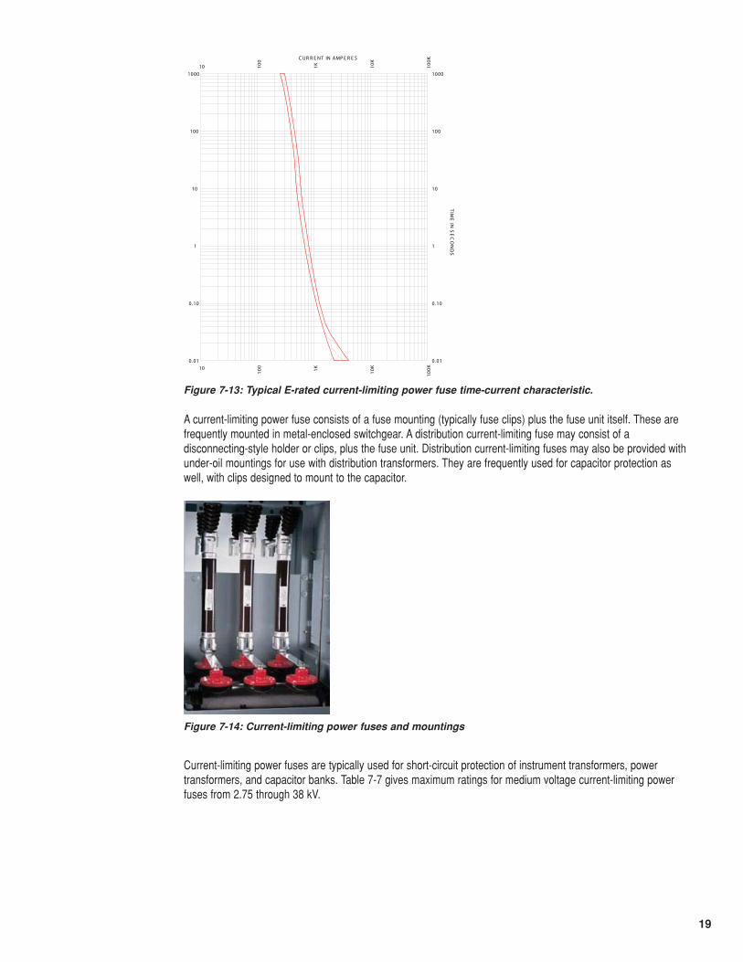
A typical time-current curve for an E-rated current-limiting power fuse is shown in figure 7-13. The fuse in figure7-13 is a 125E-rated fuse. Note that the curve starts at approximately 250 A for a minimum melting time of 1000 s.Care must be taken with backup and general-purpose current-limiting fuses so that the load current does not toexceed the E- or R-rating of the fuse. Failure to do this can result in the development of a hot-spot andsubsequent failure of the fuse and its mounting. For fuses enclosed in equipment, this can have disastrousconsequences since failure of the fuse and/or its mounting can lead to an arcing fault in the equipment. Note thatthe boundary of the characteristic, denoting the minimum-melting current, should be further derated to take intoaccount pre-loading of the fuse (consult the fuse manufacturer for details). Note that, as with low voltage fuses,the current-limiting fuse characteristic does not extend below .01 seconds since the fuse would be in its current-limiting range below this interrupting time.
19
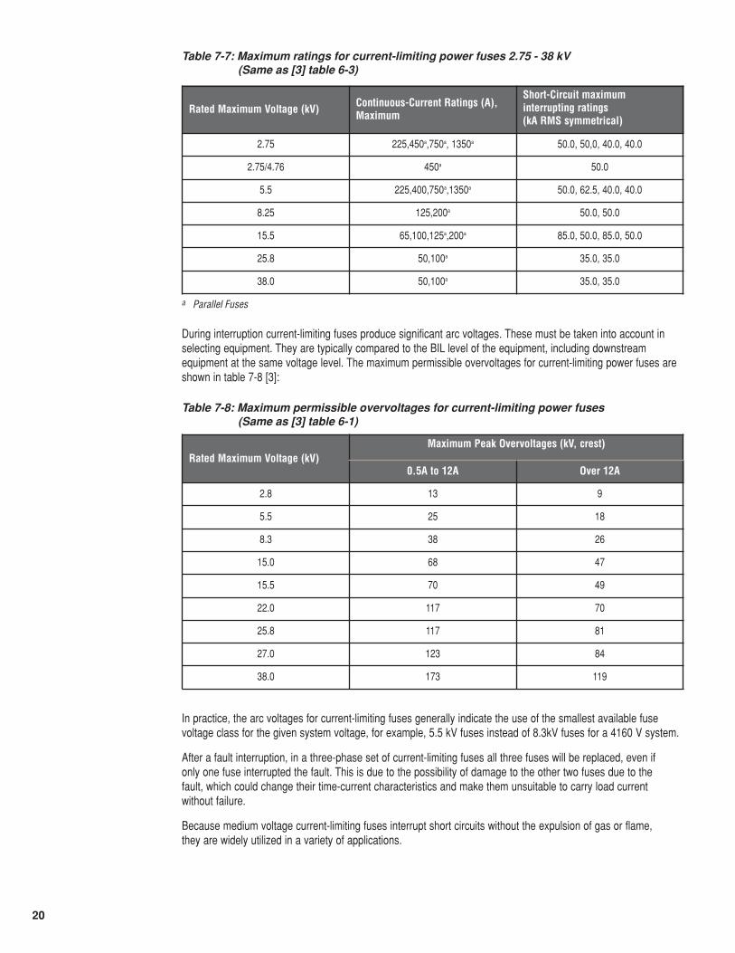
A current-limiting power fuse consists of a fuse mounting (typically fuse clips) plus the fuse unit itself. These arefrequently mounted in metal-enclosed switchgear. A distribution current-limiting fuse may consist of adisconnecting-style holder or clips, plus the fuse unit. Distribution current-limiting fuses may also be provided withunder-oil mountings for use with distribution transformers. They are frequently used for capacitor protection aswell, with clips designed to mount to the capacitor.
Current-limiting power fuses are typically used for short-circuit protection of instrument transformers, powertransformers, and capacitor banks. Table 7-7 gives maximum ratings for medium voltage current-limiting powerfuses from 2.75 through 38 kV.
10
10
100
100
1K1K
10K
10K
100K
100K
0 .01 0.01
0.10 0.10
1 1
10 10
100 100
1000 1000
C UR R E NT IN AMP E R E S
TIM
E IN
SE
CO
ND
S
Figure 7-13: Typical E-rated current-limiting power fuse time-current characteristic.
Figure 7-14: Current-limiting power fuses and mountings
20
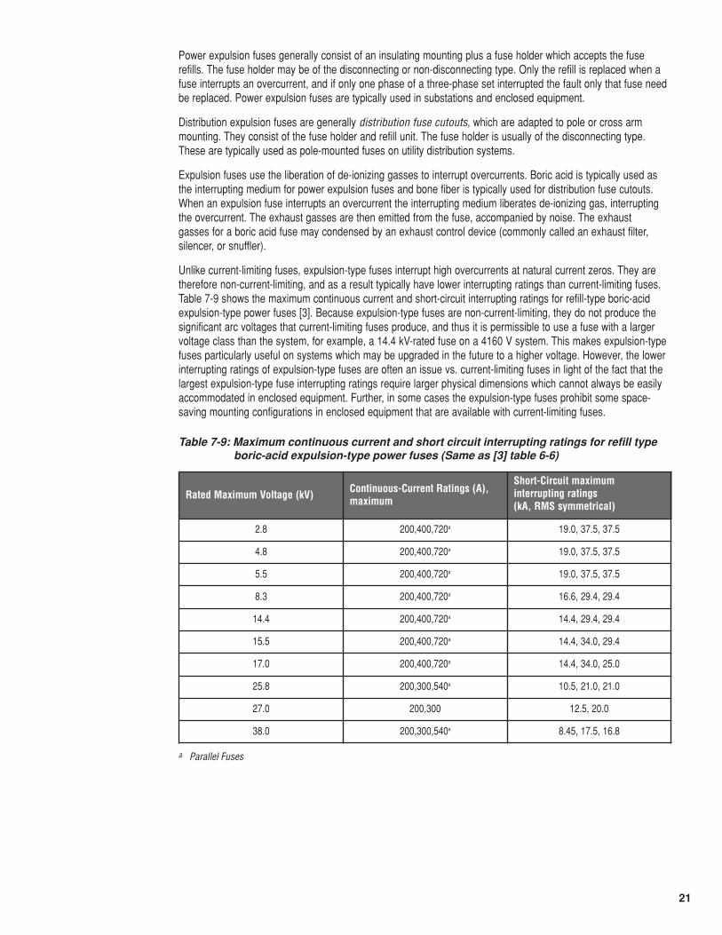
Table 7-7: Maximum ratings for current-limiting power fuses 2.75 - 38 kV (Same as [3] table 6-3)
During interruption current-limiting fuses produce significant arc voltages. These must be taken into account inselecting equipment. They are typically compared to the BIL level of the equipment, including downstreamequipment at the same voltage level. The maximum permissible overvoltages for current-limiting power fuses areshown in table 7-8 [3]:
Table 7-8: Maximum permissible overvoltages for current-limiting power fuses (Same as [3] table 6-1)
In practice, the arc voltages for current-limiting fuses generally indicate the use of the smallest available fusevoltage class for the given system voltage, for example, 5.5 kV fuses instead of 8.3kV fuses for a 4160 V system.
After a fault interruption, in a three-phase set of current-limiting fuses all three fuses will be replaced, even if only one fuse interrupted the fault. This is due to the possibility of damage to the other two fuses due to the fault, which could change their time-current characteristics and make them unsuitable to carry load current without failure.
Because medium voltage current-limiting fuses interrupt short circuits without the expulsion of gas or flame, they are widely utilized in a variety of applications.
Rated Maximum Voltage (kV) Continuous-Current Ratings (A),Maximum
Short-Circuit maximuminterrupting ratings (kA RMS symmetrical)
2.75 225,450a,750a, 1350a 50.0, 50,0, 40.0, 40.0
2.75/4.76 450a 50.0
5.5 225,400,750a,1350a 50.0, 62.5, 40.0, 40.0
8.25 125,200a 50.0, 50.0
15.5 65,100,125a,200a 85.0, 50.0, 85.0, 50.0
25.8 50,100a 35.0, 35.0
38.0 50,100a 35.0, 35.0
a Parallel Fuses
Rated Maximum Voltage (kV)Maximum Peak Overvoltages (kV, crest)
0.5A to 12A Over 12A
2.8 13 9
5.5 25 18
8.3 38 26
15.0 68 47
15.5 70 49
22.0 117 70
25.8 117 81
27.0 123 84
38.0 173 119
21
Power expulsion fuses generally consist of an insulating mounting plus a fuse holder which accepts the fuserefills. The fuse holder may be of the disconnecting or non-disconnecting type. Only the refill is replaced when afuse interrupts an overcurrent, and if only one phase of a three-phase set interrupted the fault only that fuse needbe replaced. Power expulsion fuses are typically used in substations and enclosed equipment.
Distribution expulsion fuses are generally distribution fuse cutouts, which are adapted to pole or cross armmounting. They consist of the fuse holder and refill unit. The fuse holder is usually of the disconnecting type.These are typically used as pole-mounted fuses on utility distribution systems.
Expulsion fuses use the liberation of de-ionizing gasses to interrupt overcurrents. Boric acid is typically used asthe interrupting medium for power expulsion fuses and bone fiber is typically used for distribution fuse cutouts.When an expulsion fuse interrupts an overcurrent the interrupting medium liberates de-ionizing gas, interruptingthe overcurrent. The exhaust gasses are then emitted from the fuse, accompanied by noise. The exhaust gasses for a boric acid fuse may condensed by an exhaust control device (commonly called an exhaust filter,silencer, or snuffler).
Unlike current-limiting fuses, expulsion-type fuses interrupt high overcurrents at natural current zeros. They aretherefore non-current-limiting, and as a result typically have lower interrupting ratings than current-limiting fuses.Table 7-9 shows the maximum continuous current and short-circuit interrupting ratings for refill-type boric-acidexpulsion-type power fuses [3]. Because expulsion-type fuses are non-current-limiting, they do not produce thesignificant arc voltages that current-limiting fuses produce, and thus it is permissible to use a fuse with a largervoltage class than the system, for example, a 14.4 kV-rated fuse on a 4160 V system. This makes expulsion-typefuses particularly useful on systems which may be upgraded in the future to a higher voltage. However, the lowerinterrupting ratings of expulsion-type fuses are often an issue vs. current-limiting fuses in light of the fact that thelargest expulsion-type fuse interrupting ratings require larger physical dimensions which cannot always be easilyaccommodated in enclosed equipment. Further, in some cases the expulsion-type fuses prohibit some space-saving mounting configurations in enclosed equipment that are available with current-limiting fuses.
Table 7-9: Maximum continuous current and short circuit interrupting ratings for refill typeboric-acid expulsion-type power fuses (Same as [3] table 6-6)
Rated Maximum Voltage (kV) Continuous-Current Ratings (A),maximum
Short-Circuit maximuminterrupting ratings (kA, RMS symmetrical)
2.8 200,400,720a 19.0, 37.5, 37.5
4.8 200,400,720a 19.0, 37.5, 37.5
5.5 200,400,720a 19.0, 37.5, 37.5
8.3 200,400,720a 16.6, 29.4, 29.4
14.4 200,400,720a 14.4, 29.4, 29.4
15.5 200,400,720a 14.4, 34.0, 29.4
17.0 200,400,720a 14.4, 34.0, 25.0
25.8 200,300,540a 10.5, 21.0, 21.0
27.0 200,300 12.5, 20.0
38.0 200,300,540a 8.45, 17.5, 16.8
a Parallel Fuses
22
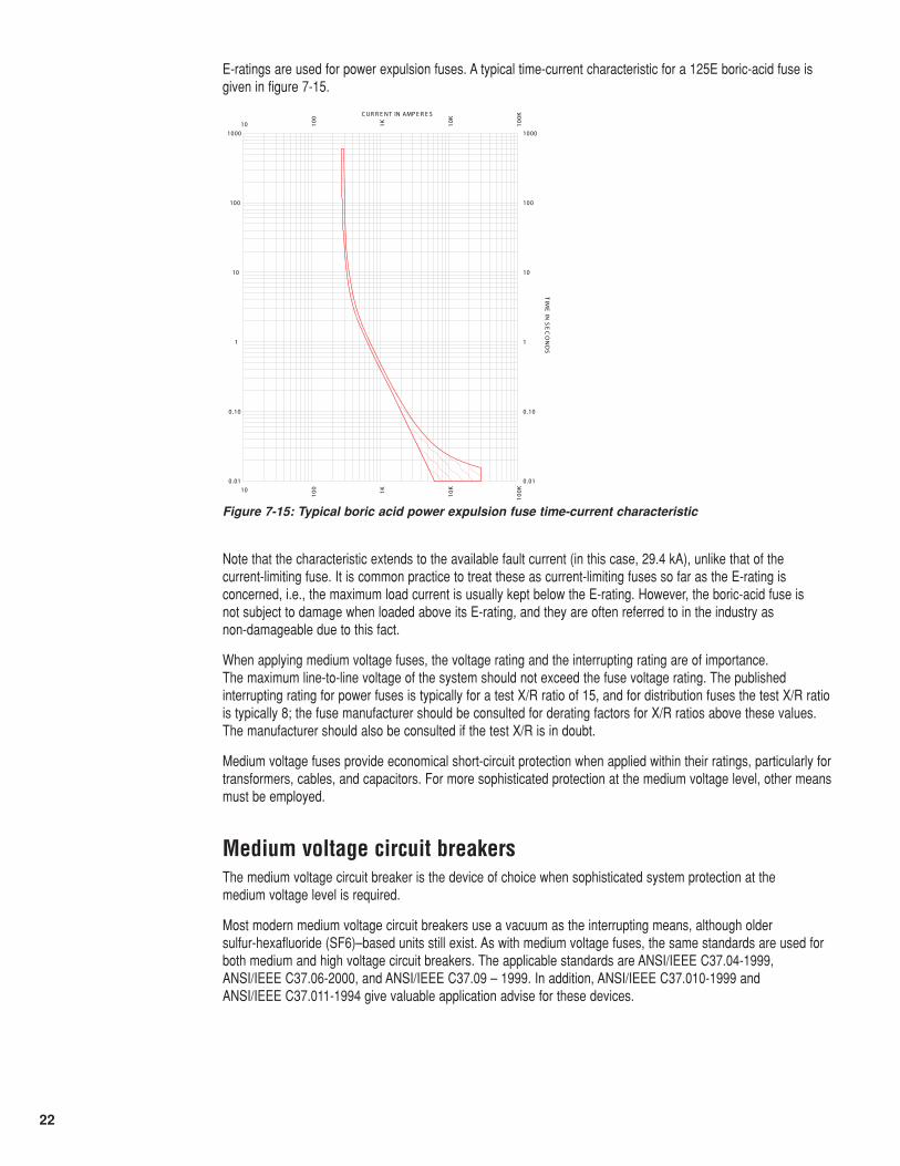
E-ratings are used for power expulsion fuses. A typical time-current characteristic for a 125E boric-acid fuse isgiven in figure 7-15.
Note that the characteristic extends to the available fault current (in this case, 29.4 kA), unlike that of the current-limiting fuse. It is common practice to treat these as current-limiting fuses so far as the E-rating isconcerned, i.e., the maximum load current is usually kept below the E-rating. However, the boric-acid fuse is not subject to damage when loaded above its E-rating, and they are often referred to in the industry as non-damageable due to this fact.
When applying medium voltage fuses, the voltage rating and the interrupting rating are of importance. The maximum line-to-line voltage of the system should not exceed the fuse voltage rating. The publishedinterrupting rating for power fuses is typically for a test X/R ratio of 15, and for distribution fuses the test X/R ratiois typically 8; the fuse manufacturer should be consulted for derating factors for X/R ratios above these values.The manufacturer should also be consulted if the test X/R is in doubt.
Medium voltage fuses provide economical short-circuit protection when applied within their ratings, particularly fortransformers, cables, and capacitors. For more sophisticated protection at the medium voltage level, other meansmust be employed.
10
10
100
100
1K1K
10K
10K
100K
100K
0 .01 0.01
0.10 0.10
1 1
10 10
100 100
1000 1000
C UR R E NT IN AMP E R E S
TIM
E IN
SE
CO
ND
S
Figure 7-15: Typical boric acid power expulsion fuse time-current characteristic
Medium voltage circuit breakersThe medium voltage circuit breaker is the device of choice when sophisticated system protection at the medium voltage level is required.
Most modern medium voltage circuit breakers use a vacuum as the interrupting means, although older sulfur-hexafluoride (SF6)–based units still exist. As with medium voltage fuses, the same standards are used forboth medium and high voltage circuit breakers. The applicable standards are ANSI/IEEE C37.04-1999, ANSI/IEEE C37.06-2000, and ANSI/IEEE C37.09 – 1999. In addition, ANSI/IEEE C37.010-1999 and ANSI/IEEE C37.011-1994 give valuable application advise for these devices.
23
Medium voltage circuit breakers are generally not equipped with integral trip units as low voltage circuit breakersare. Instead, protective relays must be used to sense abnormal conditions and trip the circuit breaker accordingly.
Most modern medium voltage circuit breakers are rated on a symmetrical current basis. The following ratingdefinitions apply [6]:
Rated Maximum Voltage: The highest RMS phase-to-phase voltage for which the circuit breaker is designed.
Rated Power Frequency: The frequency at which the circuit breaker is designed to operate.
Rated Dry Withstand Voltage: The RMS voltage that the circuit breaker in new condition is capable ofwithstanding for 1 minute under specified conditions.
Rated Wet Withstand Voltage: The RMS voltage that an outdoor circuit breaker or external components in newcondition are capable of withstanding for 10s.
Rated Lightning Impulse Withstand Voltage: The peak value of a standard 1.2 x 50µ s wave, as defined inIEEE Std 4-1978, that a circuit breaker in new condition is capable of withstanding.
Rated Continuous Current: The current in RMS symmetrical amperes that the circuit breaker is designed tocarry continuously.
Rated Interrupting Time: The maximum permissible interval between the energizing of the trip circuit at ratedcontrol voltage and the interruption of the current in the main circuit in all poles.
Rated Short Circuit Current (Required Symmetrical Interrupting Capability): The value of the symmetricalcomponent of the short-circuit current in RMS amperes at the instant of arcing contact separation that the circuitbreaker shall be required to interrupt at a specified operating voltage, on the standard operating duty cycle, andwith a DC component of less than 20% of the current value of the symmetrical component.
Required Asymmetrical Interrupting Capability: The value of the total RMS short-circuit current at the instantof arcing contact separation that the circuit breaker shall be required to interrupt at a specified operating voltageand on the standard operating duty cycle. This is based upon a standard time constant of 45ms (X/R ratio =17 for60 Hz and 14 for 50 Hz systems) and an assumed relay operating time of _ cycle.
Rated closing and latching capability: The circuit breaker shall be capable of closing and latching any powerfrequency making current whose maximum peak is equal to or less than 2.6 (for 60 Hz power frequency; 2.5 for50 Hz power frequency) times the rated short-circuit current.
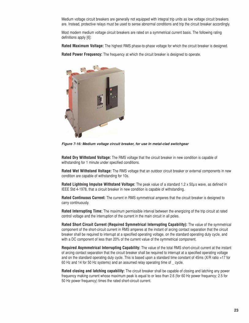
Figure 7-16: Medium voltage circuit breaker, for use In metal-clad switchgear
24
Rated Short-Time Current: The maximum short-circuit current that the circuit breaker can carry without trippingfor a specified period of time.
Maximum Permissible Tripping Delay: The maximum delay time for protective relaying to trip the circuitbreaker during short-circuit conditions, based upon the rated short-time current and short-time current-carryingtime period.
Rated Transient Recovery Voltage (TRV): At its rated maximum voltage, a circuit breaker is capable ofinterrupting three-phase grounded and ungrounded terminal faults at the rated short-circuit current in any circuit inwhich the TRV does not exceed the rated TRV envelope. For a circuit breaker rated below 100kV, the rated TRVis represented by a 1-cosine wave, with a magnitude and time-to-peak dependent upon the rated maximumvoltage of the circuit breaker.
Rated Voltage Range Factor K: Defined in earlier versions of [6] as the factor by which the rated maximumvoltage may be divided to determine the minimum voltage for which the interrupting rating varies linearly with theinterrupting rating at the rated maximum voltage by the following formula:
(7-8)
where
Ivmax is the rated short-circuit current at the maximum operating voltage
Vmax is the rated maximum operating voltage
Vop is the operating voltage where Vop
Ivop is the short-circuit current interrupting capability where Ivop ≤ Iv max x K.
For values of Vop below (Vmax ÷ K) the short-circuit interrupting capability was considered to be equal to (Iv max x K). This model was more representative of older technologies such as air-blast interruption. Becausemost modern circuit breakers employ vacuum technology, the current version of [6] assumes that K = 1., whichgives the same short circuit rating for all voltages below the rated voltage. However, in practice designs with K > 1still exist and are in common use.
Table 7-10 shows the preferred ratings for circuit breakers from [7] where K=1. Table 7-11 shows the preferredratings for circuit breakers where K > 1.
⎟⎟⎠
⎞⎜⎜⎝
⎛×=
opvvop V
VII maxmax
⎟⎟⎠⎞
⎜⎜⎝⎛≥KVmax
25
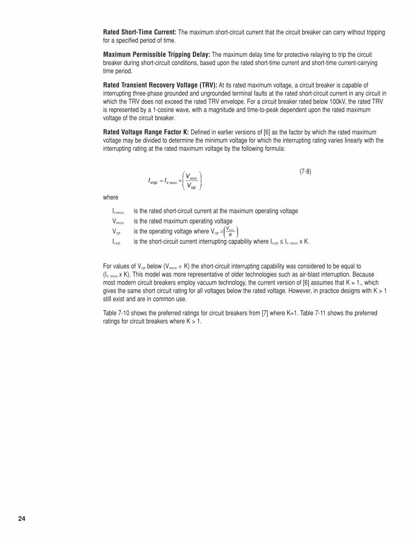
Table 7-10: Preferred ratings for indoor circuit breakers with K=1.0 (Essentially same as [7] table 1)
It should be noted that although 83 ms or 5 cycles is the “preferred” value per [6] for the rated interrupting time, 3-cycle designs are common.
Other related preferred ratings, such as dielectric ratings and capacitance switching ratings, are also given in [7].
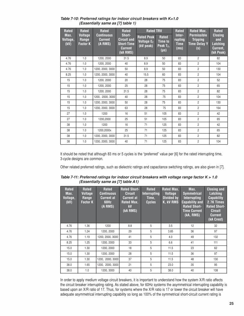
Table 7-11: Preferred ratings for indoor circuit breakers with voltage range factor K > 1.0 (Essentially same as [7] table A1)
RatedMax.
Voltage,(kV)
RatedVoltageRange
Factor K
RatedContinuous
Current(A RMS)
RatedShort-
Circuit andShort-Time
Current(kA RMS)
Rated TRV RatedInter-
ruptingTime(ms)
Rated Max.Permissible
TrippingTime Delay Y
(s)
RatedClosing
andLatchingCurrent,
(kA Peak)
Rated PeakVoltage E2
(kV peak)
RatedTime toPeak T2,
(µs)
4.76 1.0 1200, 2000 31.5 8.9 50 83 2 82
4.76 1.0 1200, 2000 40 8.9 50 83 2 104
4.76 1.0 1200, 2000, 3000 50 8.9 50 83 2 130
8.25 1.0 1200, 2000, 3000 40 15.5 60 83 2 104
15 1.0 1200, 2000 20 28 75 83 2 52
15 1.0 1200, 2000 25 28 75 83 2 65
15 1.0 1200, 2000 31.5 28 75 83 2 82
15 1.0 1200, 2000, 3000 40 28 75 83 2 104
15 1.0 1200, 2000, 3000 50 28 75 83 2 130
15 1.0 1200, 2000, 3000 63 28 75 83 2 164
27 1.0 1200 16 51 105 83 2 42
27 1.0 1200,2000 25 51 105 83 2 65
38 1.0 1200 16 71 125 83 2 42
38 1.0 1200,2000x 25 71 125 83 2 65
38 1.0 1200, 2000, 3000 31.5 71 125 83 2 82
38 1.0 1200, 2000, 3000 40 71 125 83 2 104
RatedMax.
Voltage,(kV)
RatedVoltageRange
Factor K
RatedContinuousCurrent at
60Hz(A RMS)
Rated Short-Circuit
Current atRated Max.
kV(kA RMS)
RatedInterrupting
Time,Cycles
Rated Max.Voltage
Divided byK, kV RMS
Max.SymmetricalInterrupting
Capability andRated Short-Time Current
(kA, RMS)
Closing andLatching
Capability2.7K Times
Rated Short-CircuitCurrent
(kA Crest)
4.76 1.36 1200 8.8 5 3.5 12 32
4.76 1.24 1200, 2000 29 5 3.85 36 97
4.76 1.19 1200, 2000, 3000 41 5 4.0 49 132
8.25 1.25 1200, 2000 33 5 6.6 41 111
15.0 1.30 1200, 2000 18 5 11.5 23 62
15.0 1.30 1200, 2000 28 5 11.5 36 97
15.0 1.30 1200, 2000, 3000 37 5 11.5 48 130
38.0 1.65 1200, 2000, 3000 21 5 23.0 35 95
38.0 1.0 1200, 3000 40 5 38.0 40 108
In order to apply medium voltage circuit breakers, it is important to understand how the system X/R ratio affectsthe circuit breaker interrupting rating. As stated above, for 60Hz systems the asymmetrical interrupting capability isbased upon an X/R ratio of 17. Thus, for systems where the X/R ratio is 17 or lower the circuit breaker will haveadequate asymmetrical interrupting capability so long as 100% of the symmetrical short-circuit current rating is
26
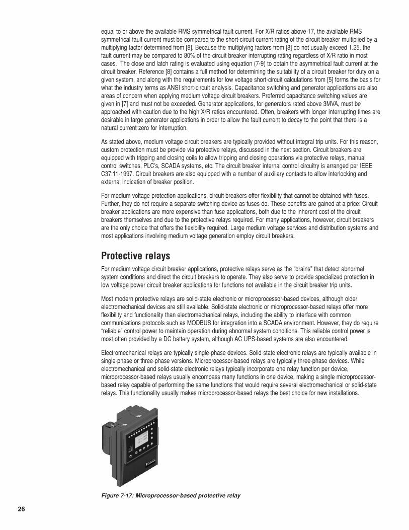
Figure 7-17: Microprocessor-based protective relay
equal to or above the available RMS symmetrical fault current. For X/R ratios above 17, the available RMSsymmetrical fault current must be compared to the short-circuit current rating of the circuit breaker multiplied by amultiplying factor determined from [8]. Because the multiplying factors from [8] do not usually exceed 1.25, thefault current may be compared to 80% of the circuit breaker interrupting rating regardless of X/R ratio in mostcases. The close and latch rating is evaluated using equation (7-9) to obtain the asymmetrical fault current at thecircuit breaker. Reference [8] contains a full method for determining the suitability of a circuit breaker for duty on agiven system, and along with the requirements for low voltage short-circuit calculations from [5] forms the basis forwhat the industry terms as ANSI short-circuit analysis. Capacitance switching and generator applications are alsoareas of concern when applying medium voltage circuit breakers. Preferred capacitance switching values aregiven in [7] and must not be exceeded. Generator applications, for generators rated above 3MVA, must beapproached with caution due to the high X/R ratios encountered. Often, breakers with longer interrupting times aredesirable in large generator applications in order to allow the fault current to decay to the point that there is anatural current zero for interruption.
As stated above, medium voltage circuit breakers are typically provided without integral trip units. For this reason,custom protection must be provide via protective relays, discussed in the next section. Circuit breakers areequipped with tripping and closing coils to allow tripping and closing operations via protective relays, manualcontrol switches, PLC’s, SCADA systems, etc. The circuit breaker internal control circuitry is arranged per IEEEC37.11-1997. Circuit breakers are also equipped with a number of auxiliary contacts to allow interlocking andexternal indication of breaker position.
For medium voltage protection applications, circuit breakers offer flexibility that cannot be obtained with fuses.Further, they do not require a separate switching device as fuses do. These benefits are gained at a price: Circuitbreaker applications are more expensive than fuse applications, both due to the inherent cost of the circuitbreakers themselves and due to the protective relays required. For many applications, however, circuit breakersare the only choice that offers the flexibility required. Large medium voltage services and distribution systems andmost applications involving medium voltage generation employ circuit breakers.
Protective relaysFor medium voltage circuit breaker applications, protective relays serve as the “brains” that detect abnormalsystem conditions and direct the circuit breakers to operate. They also serve to provide specialized protection inlow voltage power circuit breaker applications for functions not available in the circuit breaker trip units.
Most modern protective relays are solid-state electronic or microprocessor-based devices, although olderelectromechanical devices are still available. Solid-state electronic or microprocessor-based relays offer moreflexibility and functionality than electromechanical relays, including the ability to interface with commoncommunications protocols such as MODBUS for integration into a SCADA environment. However, they do require“reliable” control power to maintain operation during abnormal system conditions. This reliable control power ismost often provided by a DC battery system, although AC UPS-based systems are also encountered.
Electromechanical relays are typically single-phase devices. Solid-state electronic relays are typically available insingle-phase or three-phase versions. Microprocessor-based relays are typically three-phase devices. Whileelectromechanical and solid-state electronic relays typically incorporate one relay function per device,microprocessor-based relays usually encompass many functions in one device, making a single microprocessor-based relay capable of performing the same functions that would require several electromechanical or solid-staterelays. This functionality usually makes microprocessor-based relays the best choice for new installations.
27
Protective relays are not rated for direct connection to the power system where they are applied. For this reason,instrument transformers are used to reduce the currents and voltages to the levels for which the relays aredesigned. Instrument transformers generally fall into one of two broad categories: Current Transformers (CT’s)and Voltage Transformers (VT’s). The loads on instrument transformers, such as relays and meters, are known asburdens to distinguish them from power system loads.
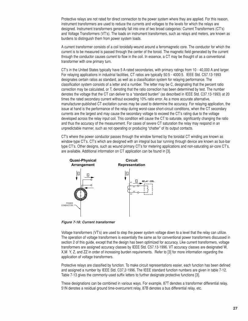
A current transformer consists of a coil toroidally-wound around a ferromagnetic core. The conductor for which thecurrent is to be measured is passed through the center of the toroid. The magnetic field generated by the currentthrough the conductor causes current to flow in the coil. In essence, a CT may be thought of as a conventionaltransformer with one primary turn.
CT’s in the United States typically have 5 A-rated secondaries, with primary ratings from 10 - 40,000 A and larger.For relaying applications in industrial facilities, CT ratios are typically 50:5 - 4000:5. IEEE Std. C57.13-1993designates certain ratios as standard, as well as a classification system for relaying performance. Theclassification system consists of a letter and a number. The letter may be C, designating that the percent ratiocorrection may be calculated, or T, denoting that the ratio correction has been determined by test. The numberdenotes the voltage that the CT can deliver to a “standard burden” (as described in IEEE Std. C37.13-1993) at 20times the rated secondary current without exceeding 10% ratio error. As a more accurate alternative,manufacturer-published CT excitation curves may be used to determine the accuracy. For relaying application, theissue at hand is the performance of the relay during worst-case short-circuit conditions, when the CT secondarycurrents are the largest and may cause the secondary voltage to exceed the CT’s rating due to the voltagedeveloped across the relay input coil. This condition will cause the CT to saturate, significantly changing the ratioand thus the accuracy of the measurement. For cases of severe CT saturation the relay may respond in anunpredictable manner, such as not operating or producing “chatter” of its output contacts.
CT's where the power conductor passes through the window formed by the toroidal CT winding are known aswindow-type CT’s. CT’s which are designed with an integral bus bar running through device are known as bus-bartype CT’s. Other designs, such as wound primary CT’s for metering applications and non-saturating air-core CT’s,are available. Additional information on CT application can be found in [3].
Voltage transformers (VT’s) are used to step the power system voltage down to a level that the relay can utilize.The operation of voltage transformers is essentially the same as for conventional power transformers discussed insection 2 of this guide, except that the design has been optimized for accuracy. Like current transformers, voltagetransformers are assigned accuracy classes by IEEE Std. C57.13-1996. VT accuracy classes are designated W,X,M Y, Z, and ZZ in order of increasing burden requirements. Refer to [3] for more information regarding theapplication of voltage transformers.
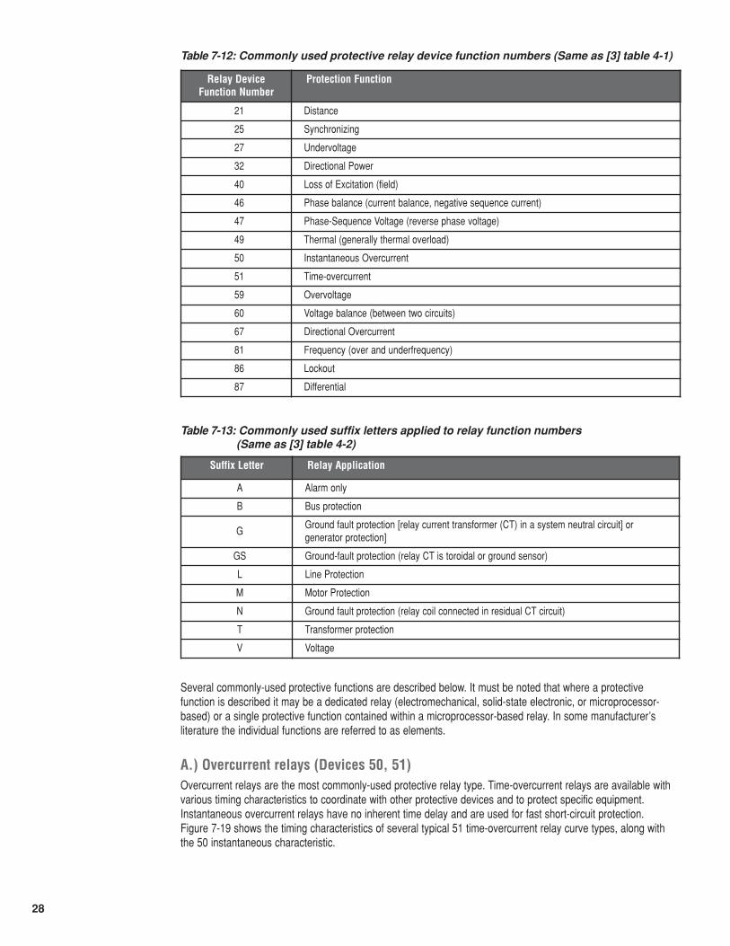
Protective relays are classified by function. To make circuit representations easier, each function has been definedand assigned a number by IEEE Std. C37.2-1996. The IEEE standard function numbers are given in table 7-12.Table 7-13 gives the commonly-used suffix letters to further designate protective functions [3].
These designations can be combined in various ways. For example, 87T denotes a transformer differential relay,51N denotes a residual ground time-overcurrent relay, 87B denotes a bus differential relay, etc.
pIsI
Quasi-Physical Arrangement
POWER CONDUCTOR
H1
H2
X1
X2
pI
sI
Circuit Representation
Figure 7-18: Current transformer
28
Table 7-12: Commonly used protective relay device function numbers (Same as [3] table 4-1)
Table 7-13: Commonly used suffix letters applied to relay function numbers (Same as [3] table 4-2)
Several commonly-used protective functions are described below. It must be noted that where a protectivefunction is described it may be a dedicated relay (electromechanical, solid-state electronic, or microprocessor-based) or a single protective function contained within a microprocessor-based relay. In some manufacturer’sliterature the individual functions are referred to as elements.
A.) Overcurrent relays (Devices 50, 51)Overcurrent relays are the most commonly-used protective relay type. Time-overcurrent relays are available withvarious timing characteristics to coordinate with other protective devices and to protect specific equipment.Instantaneous overcurrent relays have no inherent time delay and are used for fast short-circuit protection. Figure 7-19 shows the timing characteristics of several typical 51 time-overcurrent relay curve types, along withthe 50 instantaneous characteristic.
Relay DeviceFunction Number
Protection Function
21 Distance
25 Synchronizing
27 Undervoltage
32 Directional Power
40 Loss of Excitation (field)
46 Phase balance (current balance, negative sequence current)
47 Phase-Sequence Voltage (reverse phase voltage)
49 Thermal (generally thermal overload)
50 Instantaneous Overcurrent
51 Time-overcurrent
59 Overvoltage
60 Voltage balance (between two circuits)
67 Directional Overcurrent
81 Frequency (over and underfrequency)
86 Lockout
87 Differential
Suffix Letter Relay Application
A Alarm only
B Bus protection
GGround fault protection [relay current transformer (CT) in a system neutral circuit] orgenerator protection]
GS Ground-fault protection (relay CT is toroidal or ground sensor)
L Line Protection
M Motor Protection
N Ground fault protection (relay coil connected in residual CT circuit)
T Transformer protection
V Voltage
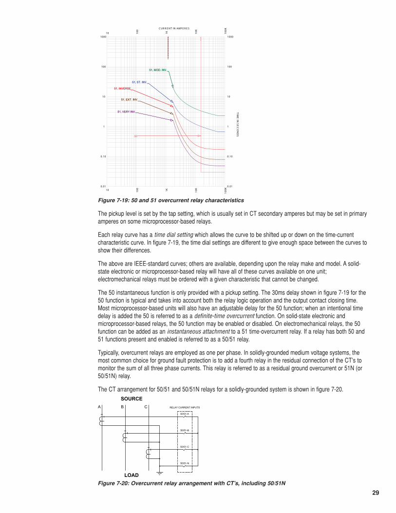
29
The pickup level is set by the tap setting, which is usually set in CT secondary amperes but may be set in primaryamperes on some microprocessor-based relays.
Each relay curve has a time dial setting which allows the curve to be shifted up or down on the time-currentcharacteristic curve. In figure 7-19, the time dial settings are different to give enough space between the curves toshow their differences.
The above are IEEE-standard curves; others are available, depending upon the relay make and model. A solid-state electronic or microprocessor-based relay will have all of these curves available on one unit;electromechanical relays must be ordered with a given characteristic that cannot be changed.
The 50 instantaneous function is only provided with a pickup setting. The 30ms delay shown in figure 7-19 for the50 function is typical and takes into account both the relay logic operation and the output contact closing time.Most microprocessor-based units will also have an adjustable delay for the 50 function; when an intentional timedelay is added the 50 is referred to as a definite-time overcurrent function. On solid-state electronic andmicroprocessor-based relays, the 50 function may be enabled or disabled. On electromechanical relays, the 50function can be added as an instantaneous attachment to a 51 time-overcurrent relay. If a relay has both 50 and51 functions present and enabled is referred to as a 50/51 relay.
Typically, overcurrent relays are employed as one per phase. In solidly-grounded medium voltage systems, themost common choice for ground fault protection is to add a fourth relay in the residual connection of the CT’s tomonitor the sum of all three phase currents. This relay is referred to as a residual ground overcurrent or 51N (or50/51N) relay.
The CT arrangement for 50/51 and 50/51N relays for a solidly-grounded system is shown in figure 7-20.
10
10
100
100
1K1K
10K
10K
100K
100K
0 .01 0.01
0.10 0.10
1 1
10 10
100 100
1000 1000
C UR R E NT IN AMP E R E S
TIM
E IN
SE
CO
ND
S
51, INVERSE
51, ST. INV.
51, MOD. INV.
51, VERY INV.
51, EXT. INV.
50
51, INVERSE
51, ST. INV.
51, MOD. INV.
51, VERY INV.
51, EXT. INV.
50
Figure 7-19: 50 and 51 overcurrent relay characteristics
RELAY CURRENT INPUTS
SOURCE
LOAD
50/51-A
50/51-B
50/51-C
50/51-N
A B C
Figure 7-20: Overcurrent relay arrangement with CT’s, including 50/51N
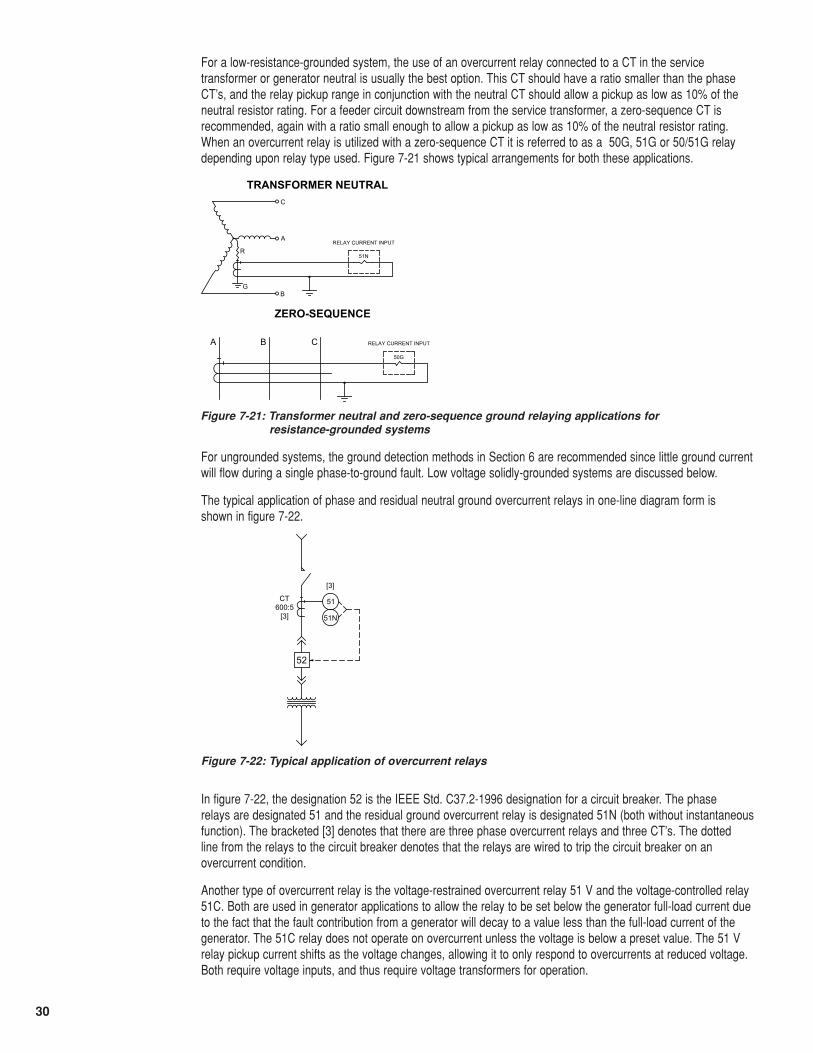
30
For a low-resistance-grounded system, the use of an overcurrent relay connected to a CT in the servicetransformer or generator neutral is usually the best option. This CT should have a ratio smaller than the phaseCT’s, and the relay pickup range in conjunction with the neutral CT should allow a pickup as low as 10% of theneutral resistor rating. For a feeder circuit downstream from the service transformer, a zero-sequence CT isrecommended, again with a ratio small enough to allow a pickup as low as 10% of the neutral resistor rating.When an overcurrent relay is utilized with a zero-sequence CT it is referred to as a 50G, 51G or 50/51G relaydepending upon relay type used. Figure 7-21 shows typical arrangements for both these applications.
For ungrounded systems, the ground detection methods in Section 6 are recommended since little ground currentwill flow during a single phase-to-ground fault. Low voltage solidly-grounded systems are discussed below.
The typical application of phase and residual neutral ground overcurrent relays in one-line diagram form is shown in figure 7-22.
In figure 7-22, the designation 52 is the IEEE Std. C37.2-1996 designation for a circuit breaker. The phase relays are designated 51 and the residual ground overcurrent relay is designated 51N (both without instantaneousfunction). The bracketed [3] denotes that there are three phase overcurrent relays and three CT’s. The dotted line from the relays to the circuit breaker denotes that the relays are wired to trip the circuit breaker on anovercurrent condition.
Another type of overcurrent relay is the voltage-restrained overcurrent relay 51 V and the voltage-controlled relay51C. Both are used in generator applications to allow the relay to be set below the generator full-load current dueto the fact that the fault contribution from a generator will decay to a value less than the full-load current of thegenerator. The 51C relay does not operate on overcurrent unless the voltage is below a preset value. The 51 Vrelay pickup current shifts as the voltage changes, allowing it to only respond to overcurrents at reduced voltage.Both require voltage inputs, and thus require voltage transformers for operation.
RELAY CURRENT INPUT
TRANSFORMER NEUTRAL
51N
RELAY CURRENT INPUT
ZERO-SEQUENCE
A B C50G
C
A
BG
R
Figure 7-21: Transformer neutral and zero-sequence ground relaying applications for resistance-grounded systems
52
51CT600:5
[3]
[3]
51N
Figure 7-22: Typical application of overcurrent relays
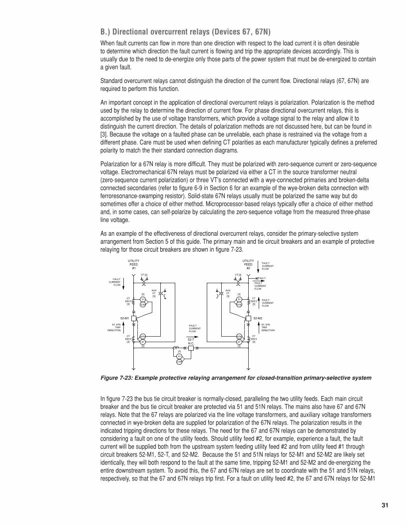
31
B.) Directional overcurrent relays (Devices 67, 67N)When fault currents can flow in more than one direction with respect to the load current it is often desirable to determine which direction the fault current is flowing and trip the appropriate devices accordingly. This is usually due to the need to de-energize only those parts of the power system that must be de-energized to containa given fault.
Standard overcurrent relays cannot distinguish the direction of the current flow. Directional relays (67, 67N) arerequired to perform this function.
An important concept in the application of directional overcurrent relays is polarization. Polarization is the methodused by the relay to determine the direction of current flow. For phase directional overcurrent relays, this isaccomplished by the use of voltage transformers, which provide a voltage signal to the relay and allow it todistinguish the current direction. The details of polarization methods are not discussed here, but can be found in[3]. Because the voltage on a faulted phase can be unreliable, each phase is restrained via the voltage from adifferent phase. Care must be used when defining CT polarities as each manufacturer typically defines a preferredpolarity to match the their standard connection diagrams.
Polarization for a 67N relay is more difficult. They must be polarized with zero-sequence current or zero-sequencevoltage. Electromechanical 67N relays must be polarized via either a CT in the source transformer neutral (zero-sequence current polarization) or three VT’s connected with a wye-connected primaries and broken-deltaconnected secondaries (refer to figure 6-9 in Section 6 for an example of the wye-broken delta connection withferroresonance-swamping resistor). Solid-state 67N relays usually must be polarized the same way but dosometimes offer a choice of either method. Microprocessor-based relays typically offer a choice of either methodand, in some cases, can self-polarize by calculating the zero-sequence voltage from the measured three-phaseline voltage.
As an example of the effectiveness of directional overcurrent relays, consider the primary-selective systemarrangement from Section 5 of this guide. The primary main and tie circuit breakers and an example of protectiverelaying for those circuit breakers are shown in figure 7-23.
In figure 7-23 the bus tie circuit breaker is normally-closed, paralleling the two utility feeds. Each main circuitbreaker and the bus tie circuit breaker are protected via 51 and 51N relays. The mains also have 67 and 67Nrelays. Note that the 67 relays are polarized via the line voltage transformers, and auxiliary voltage transformersconnected in wye-broken delta are supplied for polarization of the 67N relays. The polarization results in theindicated tripping directions for these relays. The need for the 67 and 67N relays can be demonstrated byconsidering a fault on one of the utility feeds. Should utility feed #2, for example, experience a fault, the faultcurrent will be supplied both from the upstream system feeding utility feed #2 and from utility feed #1 throughcircuit breakers 52-M1, 52-T, and 52-M2. Because the 51 and 51N relays for 52-M1 and 52-M2 are likely setidentically, they will both respond to the fault at the same time, tripping 52-M1 and 52-M2 and de-energizing theentire downstream system. To avoid this, the 67 and 67N relays are set to coordinate with the 51 and 51N relays,respectively, so that the 67 and 67N relays trip first. For a fault on utility feed #2, the 67 and 67N relays for 52-M1
N.C.
52-M252-M1
UTILITY FEED
#1
UTILITY FEED
#2
51CT600:5
[3]
[3]
51N
CT600:5
[3]
VT [3]
67
[3]
67N
AUX VT.[3]
67, 67NTRIP
DIRECTION
51 CT600:5
[3]
[3]
51N
CT600:5
[3]
VT [3]
67
[3]
67N
AUX VT.[3]
67, 67NTRIPDIRECTION
51
[3]
51N
52-T
FAULTFAULT CURRENT
FLOW
FAULT CURRENT FLOW
FAULT CURRENT FLOW
FAULT CURRENT FLOW
FAULT CURRENT FLOW
Figure 7-23: Example protective relaying arrangement for closed-transition primary-selective system
32
will not trip due to the fact that the current is flowing in the direction opposite to the tripping direction. However, the67 and 67N relays on 52-M2 will sense current in the tripping direction and trip 52-M2. The downstream system isstill energized by 52-M1 and 52-T after 52-M2 trips.
C.) Directional power relays (Device 32)Directional power relays function when the measured real power flow in the tripping direction is exceeded. Theyare used when the power flow in a given direction is undesirable or harmful to system components.
One common use of 32 relays is at the utility service when onsite generators are paralleled with the utility. Undernormal conditions, the incoming power from the utility is measured and generator power output is controlled sothat power is not exported to the utility. Should the generator controls malfunction, the generator may begin tosource power to the utility. The 32 relay would then trip the service breaker offline, isolating the system from theutility. Of course, this would not apply if surplus power is to be intentionally sold to the utility in a co-generationarrangement.
Another use of the 32 relay is for the anti-motoring of generators, should prime-mover power be lost.
32 relays are most often supplied as single-phase devices, or as a single-phase function in the case ofmicroprocessor-based relays. They require both current and voltage sensing to function.
In most applications, 32 relays should be time-delayed to allow the system to ride through momentary power swings.
D.) Undervoltage relays (Device 27)Undervoltage relays operate when the system voltage falls below a pre-determined level. They are used inmultiple applications. The most common application is as a bus undervoltage relay, which alarms or trips a busoffline if the system voltage becomes unacceptably low. In this application, the relay should be time-delayed toride through momentary dips in voltage, for example for a fault downstream from the relay.
27 relays are commonly used as the signal to an automatic bus transfer system to initiate the transfer from a failed source to an active source. In this application, also, they should be delayed to ride through momentarydips in voltage.
27 relays may also be used as permissive devices, for example to disallow closure of a circuit breaker if thesystem voltage is not above a pre-defined level. In this application the relay is typically configured to haveinstantaneous pickup, with time-delayed drop-out to insure that the system voltage has been above the presetlevel for a specified period of time before circuit breaker closure is allowed.
E.) Phase-sequence voltage relays (Device 47)47 relays generally detect the negative-sequence component of the system voltage, and are thus inherently three-phase devices. They may be set in terms of voltage balance or in terms of negative sequence voltage. Theyare used in a variety of applications, usually in conjunction with 27 and/or 59 relays.
For protection of motors, 47 relays are useful since a loss of one phase may not be detected for a running motor.This is due to the fact that a lightly-loaded motor (or group of lightly-loaded motors) may keep the voltage on thelost phase high enough to avoid pickup by a 27 relay on that phase. This fact usually justifies the use of the 47relay whenever 27 relays are used for bus or motor protection.
47 relays may also be used for permissive functions in conjunction with a 27 relay, as described above. In this rolethe 47 relay helps insure that a circuit breaker does not close if the system phase rotation is reversed, such as bythe swapping of phase cables.
As with the 27 relay, the 47 relay should have a time delay to allow the system to ride through transientconditions. When a 27 and 47 relay are combined into the same electromechanical or solid-state electronicdevice, the device is referred to as a 27/47 relay.
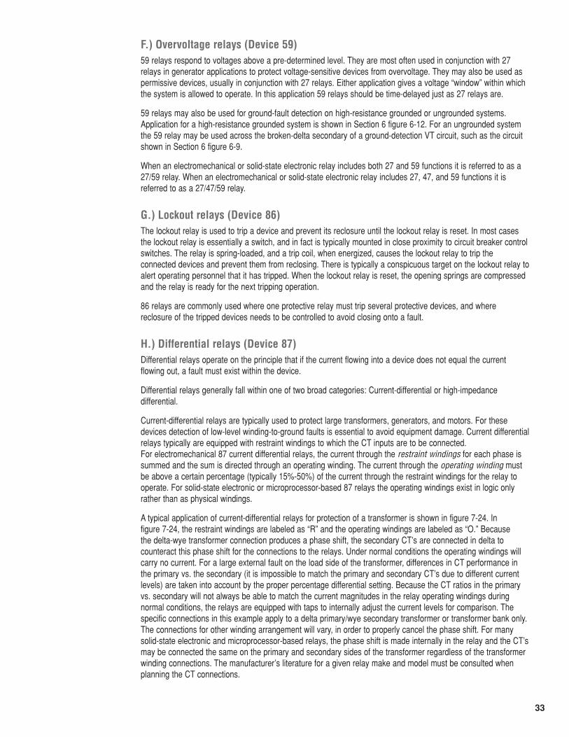
33
F.) Overvoltage relays (Device 59)59 relays respond to voltages above a pre-determined level. They are most often used in conjunction with 27relays in generator applications to protect voltage-sensitive devices from overvoltage. They may also be used aspermissive devices, usually in conjunction with 27 relays. Either application gives a voltage “window” within whichthe system is allowed to operate. In this application 59 relays should be time-delayed just as 27 relays are.
59 relays may also be used for ground-fault detection on high-resistance grounded or ungrounded systems.Application for a high-resistance grounded system is shown in Section 6 figure 6-12. For an ungrounded systemthe 59 relay may be used across the broken-delta secondary of a ground-detection VT circuit, such as the circuitshown in Section 6 figure 6-9.
When an electromechanical or solid-state electronic relay includes both 27 and 59 functions it is referred to as a27/59 relay. When an electromechanical or solid-state electronic relay includes 27, 47, and 59 functions it isreferred to as a 27/47/59 relay.
G.) Lockout relays (Device 86)The lockout relay is used to trip a device and prevent its reclosure until the lockout relay is reset. In most casesthe lockout relay is essentially a switch, and in fact is typically mounted in close proximity to circuit breaker controlswitches. The relay is spring-loaded, and a trip coil, when energized, causes the lockout relay to trip theconnected devices and prevent them from reclosing. There is typically a conspicuous target on the lockout relay toalert operating personnel that it has tripped. When the lockout relay is reset, the opening springs are compressedand the relay is ready for the next tripping operation.
86 relays are commonly used where one protective relay must trip several protective devices, and wherereclosure of the tripped devices needs to be controlled to avoid closing onto a fault.
H.) Differential relays (Device 87)Differential relays operate on the principle that if the current flowing into a device does not equal the currentflowing out, a fault must exist within the device.
Differential relays generally fall within one of two broad categories: Current-differential or high-impedancedifferential.
Current-differential relays are typically used to protect large transformers, generators, and motors. For thesedevices detection of low-level winding-to-ground faults is essential to avoid equipment damage. Current differentialrelays typically are equipped with restraint windings to which the CT inputs are to be connected. For electromechanical 87 current differential relays, the current through the restraint windings for each phase issummed and the sum is directed through an operating winding. The current through the operating winding mustbe above a certain percentage (typically 15%-50%) of the current through the restraint windings for the relay tooperate. For solid-state electronic or microprocessor-based 87 relays the operating windings exist in logic onlyrather than as physical windings.
A typical application of current-differential relays for protection of a transformer is shown in figure 7-24. In figure 7-24, the restraint windings are labeled as “R” and the operating windings are labeled as “O.” Because the delta-wye transformer connection produces a phase shift, the secondary CT’s are connected in delta tocounteract this phase shift for the connections to the relays. Under normal conditions the operating windings willcarry no current. For a large external fault on the load side of the transformer, differences in CT performance inthe primary vs. the secondary (it is impossible to match the primary and secondary CT’s due to different currentlevels) are taken into account by the proper percentage differential setting. Because the CT ratios in the primaryvs. secondary will not always be able to match the current magnitudes in the relay operating windings duringnormal conditions, the relays are equipped with taps to internally adjust the current levels for comparison. Thespecific connections in this example apply to a delta primary/wye secondary transformer or transformer bank only.The connections for other winding arrangement will vary, in order to properly cancel the phase shift. For manysolid-state electronic and microprocessor-based relays, the phase shift is made internally in the relay and the CT’smay be connected the same on the primary and secondary sides of the transformer regardless of the transformerwinding connections. The manufacturer’s literature for a given relay make and model must be consulted whenplanning the CT connections.
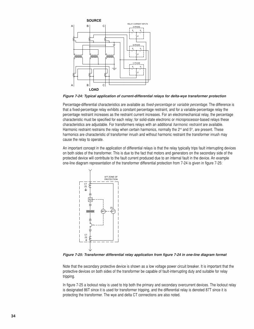
34
Percentage-differential characteristics are available as fixed-percentage or variable percentage. The difference isthat a fixed-percentage relay exhibits a constant percentage restraint, and for a variable-percentage relay thepercentage restraint increases as the restraint current increases. For an electromechanical relay, the percentagecharacteristic must be specified for each relay; for solid-state electronic or microprocessor-based relays thesecharacteristics are adjustable. For transformers relays with an additional harmonic restraint are available.Harmonic restraint restrains the relay when certain harmonics, normally the 2nd and 5th, are present. Theseharmonics are characteristic of transformer inrush and without harmonic restraint the transformer inrush maycause the relay to operate.
An important concept in the application of differential relays is that the relay typically trips fault interrupting deviceson both sides of the transformer. This is due to the fact that motors and generators on the secondary side of theprotected device will contribute to the fault current produced due to an internal fault in the device. An exampleone-line diagram representation of the transformer differential protection from 7-24 is given in figure 7-25:
Note that the secondary protective device is shown as a low voltage power circuit breaker. It is important that theprotective devices on both sides of the transformer be capable of fault-interrupting duty and suitable for relaytripping.
In figure 7-25 a lockout relay is used to trip both the primary and secondary overcurrent devices. The lockout relayis designated 86T since it is used for transformer tripping, and the differential relay is denoted 87T since it isprotecting the transformer. The wye and delta CT connections are also noted.
RELAY CURRENT INPUTS
SOURCE
LOAD
R
A B C
A B C
R
O
R R
O
R R
O
A-PHASE
B-PHASE
C-PHASE
Figure 7-24: Typical application of current-differential relays for delta-wye transformer protection
52
87T
CT[3]
[3]
86T
CT[3]
87T ZONE OF PROTECTION
Figure 7-25: Transformer differential relay application from figure 7-24 in one-line diagram format
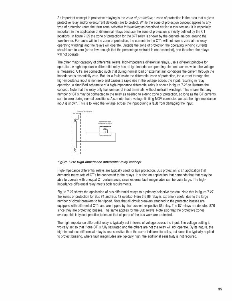
35
An important concept in protective relaying is the zone of protection; a zone of protection is the area that a givenprotective relay and/or overcurrent device(s) are to protect. While the zone of protection concept applies to anytype of protection (note the term zone selective interlocking as described earlier in this section), it is especiallyimportant in the application of differential relays because the zone of protection is strictly defined by the CTlocations. In figure 7-25 the zone of protection for the 87T relay is shown by the dashed-line box around thetransformer. For faults within the zone of protection, the currents in the CT’s will not sum to zero at the relayoperating windings and the relays will operate. Outside the zone of protection the operating winding currentsshould sum to zero (or be low enough that the percentage restraint is not exceeded), and therefore the relays will not operate.
The other major category of differential relays, high-impedance differential relays, use a different principle foroperation. A high-impedance differential relay has a high-impedance operating element, across which the voltageis measured. CT’s are connected such that during normal load or external fault conditions the current through theimpedance is essentially zero. But, for a fault inside the differential zone of protection, the current through thehigh-impedance input is non-zero and causes a rapid rise in the voltage across the input, resulting in relayoperation. A simplified schematic of a high-impedance differential relay is shown in figure 7-26 to illustrate theconcept. Note that the relay only has one set of input terminals, without restraint windings. This means that anynumber of CT’s may be connected to the relay as needed to extend zone of protection, so long as the CT currentssum to zero during normal conditions. Also note that a voltage-limiting MOV connected across the high-impedanceinput is shown. This is to keep the voltage across the input during a fault from damaging the input.
High-impedance differential relays are typically used for bus protection. Bus protection is an application thatdemands many sets of CT’s be connected to the relays. It is also an application that demands that that relay beable to operate with unequal CT performance, since external fault magnitudes can be quite large. The high-impedance differential relay meets both requirements.
Figure 7-27 shows the application of bus differential relays to a primary-selective system. Note that in figure 7-27the zones of protection for Bus #1 and Bus #2 overlap. Here the 86 relay is extremely useful due to the largenumber of circuit breakers to be tripped. Note that all circuit breakers attached to the protected busses areequipped with differential CT’s and are tripped by that busses’ respective 86 relay. The 87 relays are denoted 87Bsince they are protecting busses. The same applies for the 86B relays. Note also that the protective zonesoverlap; this is typical practice to insure that all parts of the bus work are protected.
The high-impedance differential relay is typically set in terms of voltage across the input. The voltage setting istypically set so that if one CT is fully saturated and the others are not the relay will not operate. By its nature, thehigh-impedance differential relay is less sensitive than the current-differential relay, but since it is typically appliedto protect bussing, where fault magnitudes are typically high, the additional sensitivity is not required.
Z
HIGH-IMPEDANCE DIFFERENTIAL RELAY
MOV
ZONE OF PROTECTION
Figure 7-26: High-impedance differential relay concept
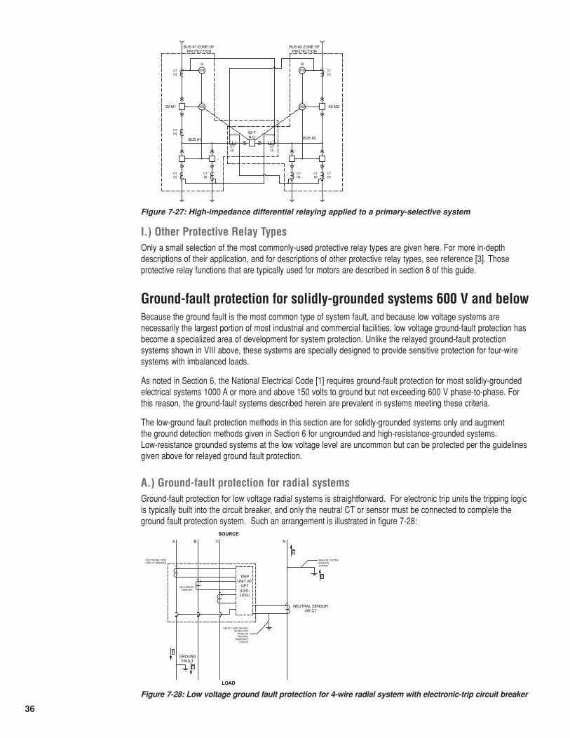
36
Ground-fault protection for solidly-grounded systems 600 V and belowBecause the ground fault is the most common type of system fault, and because low voltage systems arenecessarily the largest portion of most industrial and commercial facilities, low voltage ground-fault protection hasbecome a specialized area of development for system protection. Unlike the relayed ground-fault protectionsystems shown in VIII above, these systems are specially designed to provide sensitive protection for four-wiresystems with imbalanced loads.
As noted in Section 6, the National Electrical Code [1] requires ground-fault protection for most solidly-groundedelectrical systems 1000 A or more and above 150 volts to ground but not exceeding 600 V phase-to-phase. Forthis reason, the ground-fault systems described herein are prevalent in systems meeting these criteria.
The low-ground fault protection methods in this section are for solidly-grounded systems only and augment the ground detection methods given in Section 6 for ungrounded and high-resistance-grounded systems. Low-resistance grounded systems at the low voltage level are uncommon but can be protected per the guidelinesgiven above for relayed ground fault protection.
A.) Ground-fault protection for radial systemsGround-fault protection for low voltage radial systems is straightforward. For electronic trip units the tripping logicis typically built into the circuit breaker, and only the neutral CT or sensor must be connected to complete theground fault protection system. Such an arrangement is illustrated in figure 7-28:
I.) Other Protective Relay TypesOnly a small selection of the most commonly-used protective relay types are given here. For more in-depthdescriptions of their application, and for descriptions of other protective relay types, see reference [3]. Thoseprotective relay functions that are typically used for motors are described in section 8 of this guide.
N.C.
52-M252-M1
BUS #1
87BCT[3]
[3]
86B
CT[3] 52-T
BUS #2
CT[3]
CT[3]
CT[3]
CT[3]
87B CT[3]
[3]
86B
CT[3]
CT[3]
CT[3]
BUS #1 ZONE OF PROTECTION
BUS #2 ZONE OF PROTECTION
Figure 7-27: High-impedance differential relaying applied to a primary-selective system
FI
CB CURRENT SENSORS
SOURCE
LOAD
A B C N
ELECTRONIC-TRIP CIRCUIT BREAKER
TRIPUNIT W/
GFT(LSG,LSIG)
NEUTRAL SENSOR OR CT
SAFETY GROUND MAY OR MAY NOT
EXIST ON NEUTRAL
SENSOR/CT CIRCUIT
MAIN OR SYSTEMBONDINGJUMPER
GROUNDFAULT
FI
FI
FI
Figure 7-28: Low voltage ground fault protection for 4-wire radial system with electronic-trip circuit breaker
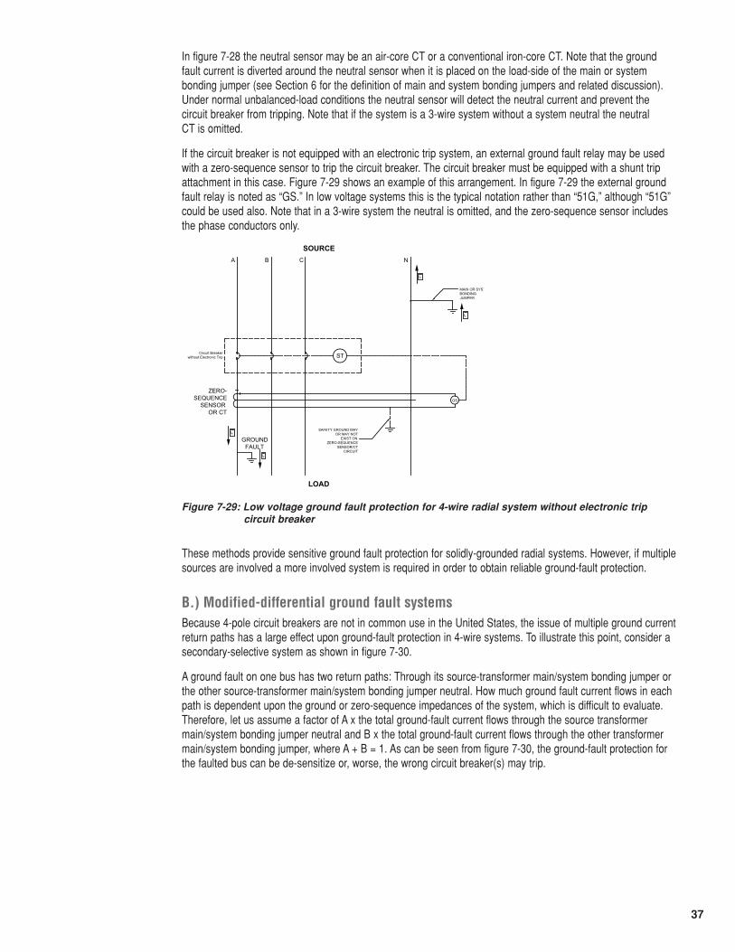
37
In figure 7-28 the neutral sensor may be an air-core CT or a conventional iron-core CT. Note that the ground fault current is diverted around the neutral sensor when it is placed on the load-side of the main or systembonding jumper (see Section 6 for the definition of main and system bonding jumpers and related discussion).Under normal unbalanced-load conditions the neutral sensor will detect the neutral current and prevent the circuit breaker from tripping. Note that if the system is a 3-wire system without a system neutral the neutral CT is omitted.
If the circuit breaker is not equipped with an electronic trip system, an external ground fault relay may be usedwith a zero-sequence sensor to trip the circuit breaker. The circuit breaker must be equipped with a shunt tripattachment in this case. Figure 7-29 shows an example of this arrangement. In figure 7-29 the external groundfault relay is noted as “GS.” In low voltage systems this is the typical notation rather than “51G,” although “51G”could be used also. Note that in a 3-wire system the neutral is omitted, and the zero-sequence sensor includesthe phase conductors only.
These methods provide sensitive ground fault protection for solidly-grounded radial systems. However, if multiplesources are involved a more involved system is required in order to obtain reliable ground-fault protection.
B.) Modified-differential ground fault systemsBecause 4-pole circuit breakers are not in common use in the United States, the issue of multiple ground currentreturn paths has a large effect upon ground-fault protection in 4-wire systems. To illustrate this point, consider asecondary-selective system as shown in figure 7-30.
A ground fault on one bus has two return paths: Through its source-transformer main/system bonding jumper orthe other source-transformer main/system bonding jumper neutral. How much ground fault current flows in eachpath is dependent upon the ground or zero-sequence impedances of the system, which is difficult to evaluate.Therefore, let us assume a factor of A x the total ground-fault current flows through the source transformermain/system bonding jumper neutral and B x the total ground-fault current flows through the other transformermain/system bonding jumper, where A + B = 1. As can be seen from figure 7-30, the ground-fault protection forthe faulted bus can be de-sensitize or, worse, the wrong circuit breaker(s) may trip.
FI
SOURCE
LOAD
A B C N
Circuit Breaker without Electronic Trip
ZERO-SEQUENCE
SENSOR OR CT
SAFETY GROUND MAY OR MAY NOT
EXIST ON ZERO-SEQUENCE
SENSOR/CT CIRCUIT
BONDINGJUMPER
GROUNDFAULT
FI
FI
FI
ST
GS
Figure 7-29: Low voltage ground fault protection for 4-wire radial system without electronic trip circuit breaker
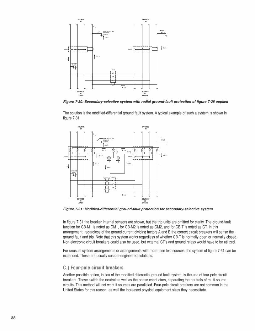
38
The solution is the modified-differential ground fault system. A typical example of such a system is shown in figure 7-31:
In figure 7-31 the breaker internal sensors are shown, but the trip units are omitted for clarity. The ground-faultfunction for CB-M1 is noted as GM1, for CB-M2 is noted as GM2, and for CB-T is noted as GT. In thisarrangement, regardless of the ground current dividing factors A and B the correct circuit breakers will sense theground fault and trip. Note that this system works regardless of whether CB-T is normally-open or normally-closed.Non-electronic circuit breakers could also be used, but external CT’s and ground relays would have to be utilized.
For unusual system arrangements or arrangements with more then two sources, the system of figure 7-31 can beexpanded. These are usually custom-engineered solutions.
C.) Four-pole circuit breakersAnother possible option, in lieu of the modified differential ground fault system, is the use of four-pole circuitbreakers. These switch the neutral as well as the phase conductors, separating the neutrals of multi-sourcecircuits. This method will not work if sources are paralleled. Four-pole circuit breakers are not common in theUnited States for this reason, as well the increased physical equipment sizes they necessitate.
SOURCE #1
SOURCE #1
LOADS
A B C N
MAIN OR SYSTEMBONDINGJUMPER
GROUNDFAULT
SOURCE #1
A B C N
SOURCE #2
LOADS
CB-M1 CB-M2
CB-T
IF
IF
A x IF
IF
B x IF
B x IF
B x IF
B x IF
Figure 7-30: Secondary-selective system with radial ground-fault protection of figure 7-28 applied
SOURCE #1
SOURCE #1
LOADS
A B C N
MAIN OR SYSTEMBONDINGJUMPER
GROUNDFAULT
SOURCE #1
A B C N
SOURCE #2
LOADS
CB-M1 CB-M2
CB-T
IF
IF
A x IF
IF
B x IF
B x IF
B x IF
GT
GM1 GM2
B x IF
B x IFA x IFIF B x IF
0IF
B x IF
A x IF
B x IF
Figure 7-31: Modified-differential ground-fault protection for secondary-selective system
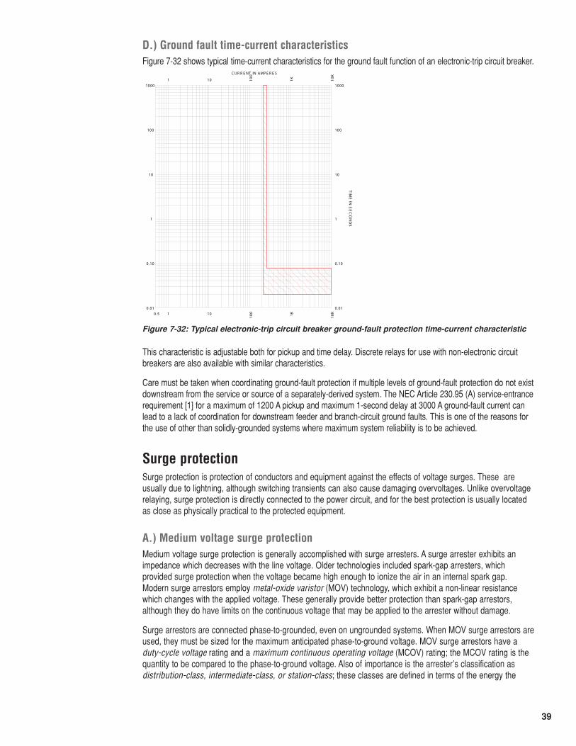
39
D.) Ground fault time-current characteristicsFigure 7-32 shows typical time-current characteristics for the ground fault function of an electronic-trip circuit breaker.
This characteristic is adjustable both for pickup and time delay. Discrete relays for use with non-electronic circuitbreakers are also available with similar characteristics.
Care must be taken when coordinating ground-fault protection if multiple levels of ground-fault protection do not existdownstream from the service or source of a separately-derived system. The NEC Article 230.95 (A) service-entrancerequirement [1] for a maximum of 1200 A pickup and maximum 1-second delay at 3000 A ground-fault current canlead to a lack of coordination for downstream feeder and branch-circuit ground faults. This is one of the reasons forthe use of other than solidly-grounded systems where maximum system reliability is to be achieved.
0.5 1
1
10
10
100
100
1K1K
10K
10K
0 .01 0.01
0.10 0.10
1 1
10 10
100 100
1000 1000
C UR R E NT IN AMP E R E S
TIM
E IN
SE
CO
ND
S
Figure 7-32: Typical electronic-trip circuit breaker ground-fault protection time-current characteristic
Surge protectionSurge protection is protection of conductors and equipment against the effects of voltage surges. These areusually due to lightning, although switching transients can also cause damaging overvoltages. Unlike overvoltagerelaying, surge protection is directly connected to the power circuit, and for the best protection is usually locatedas close as physically practical to the protected equipment.
A.) Medium voltage surge protectionMedium voltage surge protection is generally accomplished with surge arresters. A surge arrester exhibits animpedance which decreases with the line voltage. Older technologies included spark-gap arresters, whichprovided surge protection when the voltage became high enough to ionize the air in an internal spark gap.Modern surge arrestors employ metal-oxide varistor (MOV) technology, which exhibit a non-linear resistancewhich changes with the applied voltage. These generally provide better protection than spark-gap arrestors,although they do have limits on the continuous voltage that may be applied to the arrester without damage.
Surge arrestors are connected phase-to-grounded, even on ungrounded systems. When MOV surge arrestors areused, they must be sized for the maximum anticipated phase-to-ground voltage. MOV surge arrestors have aduty-cycle voltage rating and a maximum continuous operating voltage (MCOV) rating; the MCOV rating is thequantity to be compared to the phase-to-ground voltage. Also of importance is the arrester’s classification asdistribution-class, intermediate-class, or station-class; these classes are defined in terms of the energy the
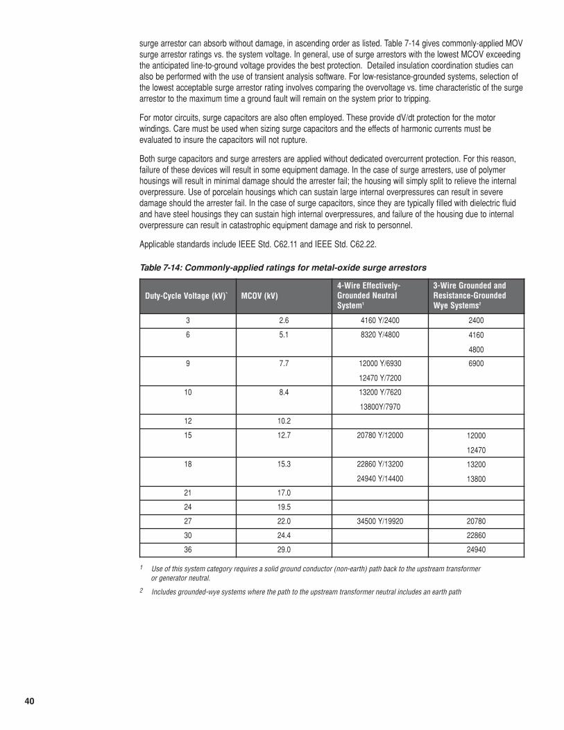
40
surge arrestor can absorb without damage, in ascending order as listed. Table 7-14 gives commonly-applied MOVsurge arrestor ratings vs. the system voltage. In general, use of surge arrestors with the lowest MCOV exceedingthe anticipated line-to-ground voltage provides the best protection. Detailed insulation coordination studies canalso be performed with the use of transient analysis software. For low-resistance-grounded systems, selection ofthe lowest acceptable surge arrestor rating involves comparing the overvoltage vs. time characteristic of the surgearrestor to the maximum time a ground fault will remain on the system prior to tripping.
For motor circuits, surge capacitors are also often employed. These provide dV/dt protection for the motorwindings. Care must be used when sizing surge capacitors and the effects of harmonic currents must beevaluated to insure the capacitors will not rupture.
Both surge capacitors and surge arresters are applied without dedicated overcurrent protection. For this reason,failure of these devices will result in some equipment damage. In the case of surge arresters, use of polymerhousings will result in minimal damage should the arrester fail; the housing will simply split to relieve the internaloverpressure. Use of porcelain housings which can sustain large internal overpressures can result in severedamage should the arrester fail. In the case of surge capacitors, since they are typically filled with dielectric fluidand have steel housings they can sustain high internal overpressures, and failure of the housing due to internaloverpressure can result in catastrophic equipment damage and risk to personnel.
Applicable standards include IEEE Std. C62.11 and IEEE Std. C62.22.
Table 7-14: Commonly-applied ratings for metal-oxide surge arrestors
Duty-Cycle Voltage (kV)` MCOV (kV)4-Wire Effectively-Grounded NeutralSystem1
3-Wire Grounded andResistance-GroundedWye Systems2
3 2.6 4160 Y/2400 2400
6 5.1 8320 Y/4800 4160
4800
9 7.7 12000 Y/6930
12470 Y/7200
6900
10 8.4 13200 Y/7620
13800Y/7970
12 10.2
15 12.7 20780 Y/12000 12000
12470
18 15.3 22860 Y/13200
24940 Y/14400
13200
13800
21 17.0
24 19.5
27 22.0 34500 Y/19920 20780
30 24.4 22860
36 29.0 24940
1 Use of this system category requires a solid ground conductor (non-earth) path back to the upstream transformer or generator neutral.
2 Includes grounded-wye systems where the path to the upstream transformer neutral includes an earth path
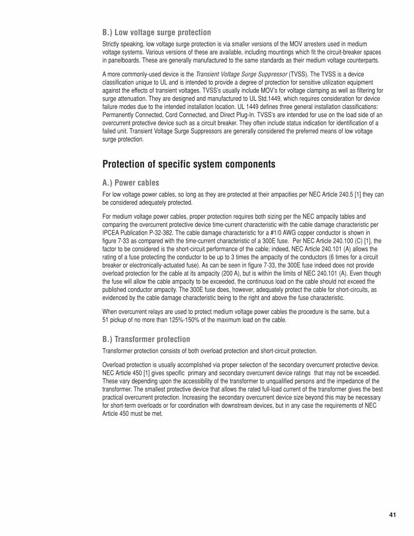
41
B.) Low voltage surge protectionStrictly speaking, low voltage surge protection is via smaller versions of the MOV arresters used in mediumvoltage systems. Various versions of these are available, including mountings which fit the circuit-breaker spacesin panelboards. These are generally manufactured to the same standards as their medium voltage counterparts.
A more commonly-used device is the Transient Voltage Surge Suppressor (TVSS). The TVSS is a deviceclassification unique to UL and is intended to provide a degree of protection for sensitive utilization equipmentagainst the effects of transient voltages. TVSS’s usually include MOV’s for voltage clamping as well as filtering forsurge attenuation. They are designed and manufactured to UL Std.1449, which requires consideration for devicefailure modes due to the intended installation location. UL 1449 defines three general installation classifications:Permanently Connected, Cord Connected, and Direct Plug-In. TVSS’s are intended for use on the load side of anovercurrent protective device such as a circuit breaker. They often include status indication for identification of afailed unit. Transient Voltage Surge Suppressors are generally considered the preferred means of low voltagesurge protection.
Protection of specific system components
A.) Power cablesFor low voltage power cables, so long as they are protected at their ampacities per NEC Article 240.5 [1] they canbe considered adequately protected.
For medium voltage power cables, proper protection requires both sizing per the NEC ampacity tables andcomparing the overcurrent protective device time-current characteristic with the cable damage characteristic perIPCEA Publication P-32-382. The cable damage characteristic for a #1/0 AWG copper conductor is shown infigure 7-33 as compared with the time-current characteristic of a 300E fuse. Per NEC Article 240.100 (C) [1], thefactor to be considered is the short-circuit performance of the cable; indeed, NEC Article 240.101 (A) allows therating of a fuse protecting the conductor to be up to 3 times the ampacity of the conductors (6 times for a circuitbreaker or electronically-actuated fuse). As can be seen in figure 7-33, the 300E fuse indeed does not provideoverload protection for the cable at its ampacity (200 A), but is within the limits of NEC 240.101 (A). Even thoughthe fuse will allow the cable ampacity to be exceeded, the continuous load on the cable should not exceed thepublished conductor ampacity. The 300E fuse does, however, adequately protect the cable for short-circuits, asevidenced by the cable damage characteristic being to the right and above the fuse characteristic.
When overcurrent relays are used to protect medium voltage power cables the procedure is the same, but a 51 pickup of no more than 125%-150% of the maximum load on the cable.
B.) Transformer protectionTransformer protection consists of both overload protection and short-circuit protection.
Overload protection is usually accomplished via proper selection of the secondary overcurrent protective device.NEC Article 450 [1] gives specific primary and secondary overcurrent device ratings that may not be exceeded.These vary depending upon the accessibility of the transformer to unqualified persons and the impedance of thetransformer. The smallest protective device that allows the rated full-load current of the transformer gives the bestpractical overcurrent protection. Increasing the secondary overcurrent device size beyond this may be necessaryfor short-term overloads or for coordination with downstream devices, but in any case the requirements of NECArticle 450 must be met.
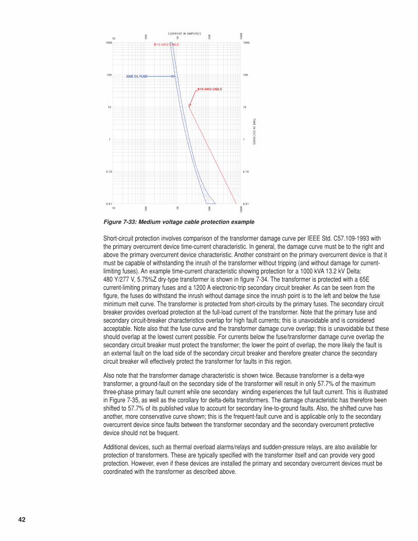
42
Short-circuit protection involves comparison of the transformer damage curve per IEEE Std. C57.109-1993 withthe primary overcurrent device time-current characteristic. In general, the damage curve must be to the right andabove the primary overcurrent device characteristic. Another constraint on the primary overcurrent device is that itmust be capable of withstanding the inrush of the transformer without tripping (and without damage for current-limiting fuses). An example time-current characteristic showing protection for a 1000 kVA 13.2 kV Delta: 480 Y/277 V, 5.75%Z dry-type transformer is shown in figure 7-34. The transformer is protected with a 65Ecurrent-limiting primary fuses and a 1200 A electronic-trip secondary circuit breaker. As can be seen from thefigure, the fuses do withstand the inrush without damage since the inrush point is to the left and below the fuseminimum melt curve. The transformer is protected from short-circuits by the primary fuses. The secondary circuitbreaker provides overload protection at the full-load current of the transformer. Note that the primary fuse andsecondary circuit-breaker characteristics overlap for high fault currents; this is unavoidable and is consideredacceptable. Note also that the fuse curve and the transformer damage curve overlap; this is unavoidable but theseshould overlap at the lowest current possible. For currents below the fuse/transformer damage curve overlap thesecondary circuit breaker must protect the transformer; the lower the point of overlap, the more likely the fault isan external fault on the load side of the secondary circuit breaker and therefore greater chance the secondarycircuit breaker will effectively protect the transformer for faults in this region.
Also note that the transformer damage characteristic is shown twice. Because transformer is a delta-wyetransformer, a ground-fault on the secondary side of the transformer will result in only 57.7% of the maximumthree-phase primary fault current while one secondary winding experiences the full fault current. This is illustratedin Figure 7-35, as well as the corollary for delta-delta transformers. The damage characteristic has therefore beenshifted to 57.7% of its published value to account for secondary line-to-ground faults. Also, the shifted curve hasanother, more conservative curve shown; this is the frequent-fault curve and is applicable only to the secondaryovercurrent device since faults between the transformer secondary and the secondary overcurrent protectivedevice should not be frequent.
Additional devices, such as thermal overload alarms/relays and sudden-pressure relays, are also available forprotection of transformers. These are typically specified with the transformer itself and can provide very goodprotection. However, even if these devices are installed the primary and secondary overcurrent devices must becoordinated with the transformer as described above.
#1/0 AWG CABLE
10
10
100
100
1K1K
10K
10K
100K
100K
0 .01 0.01
0.10 0.10
1 1
10 10
100 100
1000 1000
C UR R E NT IN AMP E R E S
TIM
E IN
SE
CO
ND
S
#1/0 AWG CABLE
300E C/L FUSE
#1/0 AWG CABLE
300E C/L FUSE
Figure 7-33: Medium voltage cable protection example
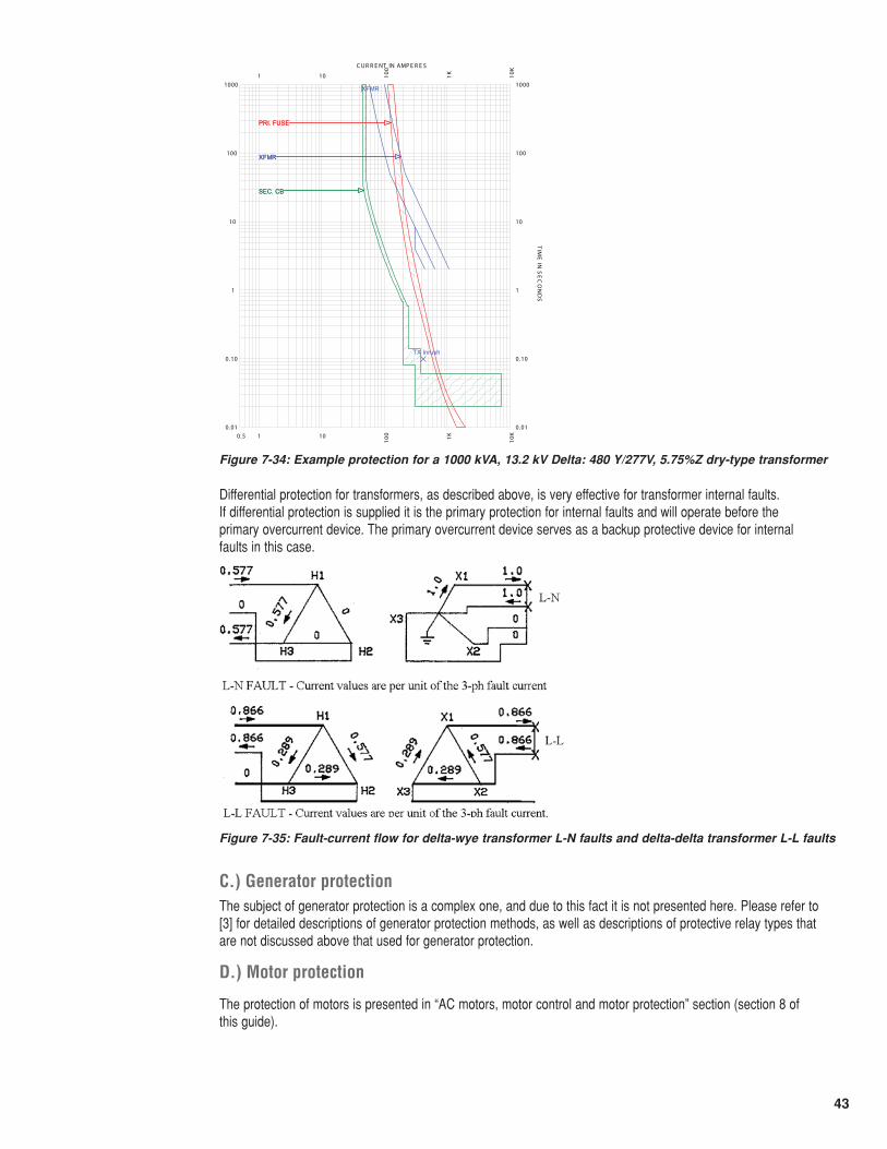
43
Differential protection for transformers, as described above, is very effective for transformer internal faults. If differential protection is supplied it is the primary protection for internal faults and will operate before the primary overcurrent device. The primary overcurrent device serves as a backup protective device for internalfaults in this case.
C.) Generator protectionThe subject of generator protection is a complex one, and due to this fact it is not presented here. Please refer to[3] for detailed descriptions of generator protection methods, as well as descriptions of protective relay types thatare not discussed above that used for generator protection.
D.) Motor protection
The protection of motors is presented in “AC motors, motor control and motor protection” section (section 8 of this guide).
TX Inrush
XFMR
0.5 1
1
10
10
100
100
1K1K
10K
10K
0 .01 0.01
0.10 0.10
1 1
10 10
100 100
1000 1000
C UR R E NT IN AMP E R E S
TIM
E IN
SE
CO
ND
S
PRI. FUSE
XFMR
SEC. CB
PRI. FUSE
XFMR
SEC. CB
Figure 7-34: Example protection for a 1000 kVA, 13.2 kV Delta: 480 Y/277V, 5.75%Z dry-type transformer
Figure 7-35: Fault-current flow for delta-wye transformer L-N faults and delta-delta transformer L-L faults
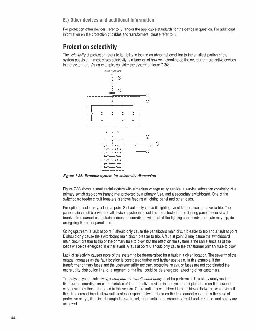
44
E.) Other devices and additional information
For protection other devices, refer to [3] and/or the applicable standards for the device in question. For additionalinformation on the protection of cables and transformers, please refer to [3].
Protection selectivityThe selectivity of protection refers to its ability to isolate an abnormal condition to the smallest portion of thesystem possible. In most cases selectivity is a function of how well-coordinated the overcurrent protective devicesin the system are. As an example, consider the system of figure 7-36:
Figure 7-36 shows a small radial system with a medium voltage utility service, a service substation consisting of aprimary switch step-down transformer protected by a primary fuse, and a secondary switchboard. One of theswitchboard feeder circuit breakers is shown feeding al lighting panel and other loads.
For optimum selectivity, a fault at point G should only cause its lighting panel feeder circuit breaker to trip. Thepanel main circuit breaker and all devices upstream should not be affected. If the lighting panel feeder circuitbreaker time-current characteristic does not coordinate with that of the lighting panel main, the main may trip, de-energizing the entire panelboard.
Going upstream, a fault at point F should only cause the panelboard main circuit breaker to trip and a fault at pointE should only cause the switchboard main circuit breaker to trip. A fault at point D may cause the switchboardmain circuit breaker to trip or the primary fuse to blow, but the effect on the system is the same since all of theloads will be de-energized in either event. A fault at point C should only cause the transformer primary fuse to blow.
Lack of selectivity causes more of the system to be de-energized for a fault in a given location. The severity of theoutage increases as the fault location is considered farther and farther upstream. In this example, if thetransformer primary fuses and the upstream utility recloser, protective relays, or fuses are not coordinated theentire utility distribution line, or a segment of the line, could be de-energized, affecting other customers.
To analyze system selectivity, a time-current coordination study must be performed. This study analyzes thetime-current coordination characteristics of the protective devices in the system and plots them on time currentcurves such as those illustrated in this section. Coordination is considered to be achieved between two devices iftheir time-current bands show sufficient clear space between them on the time-current curve or, in the case ofprotective relays, if sufficient margin for overtravel, manufacturing tolerances, circuit breaker speed, and safety areachieved.
UTILITY SERVICE
A
B
C
D
E
F
G
Figure 7-36: Example system for selectivity discussion
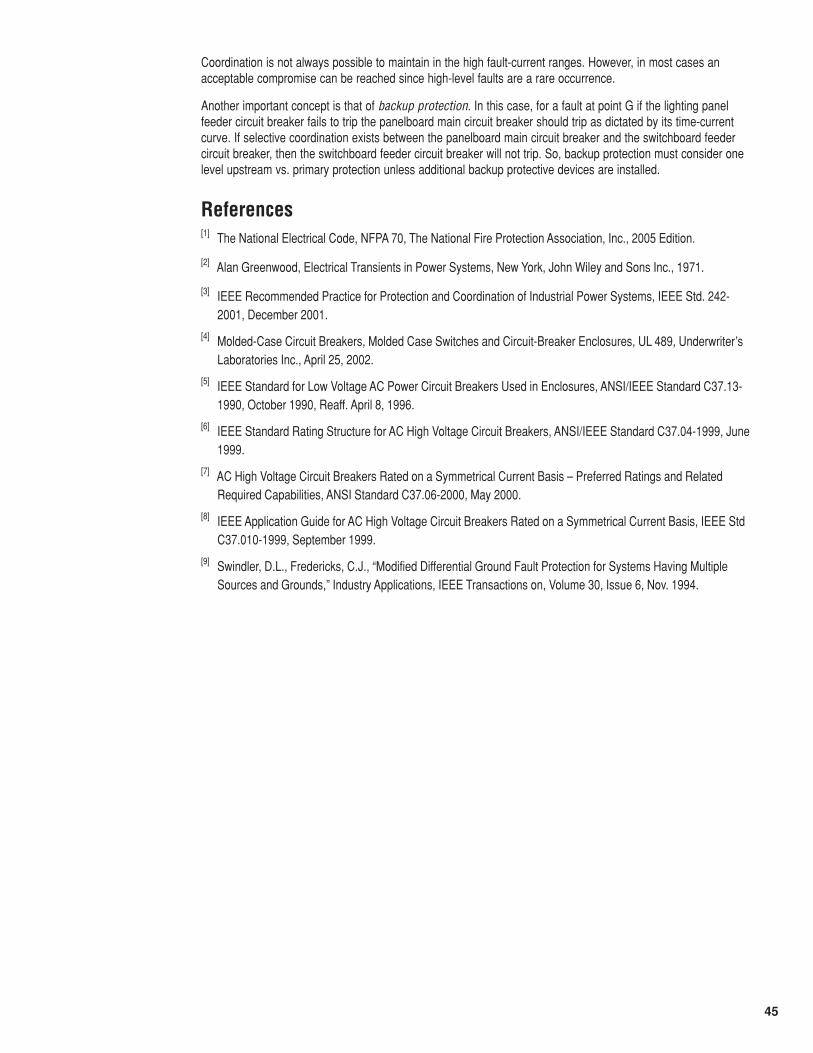
45
Coordination is not always possible to maintain in the high fault-current ranges. However, in most cases anacceptable compromise can be reached since high-level faults are a rare occurrence.
Another important concept is that of backup protection. In this case, for a fault at point G if the lighting panelfeeder circuit breaker fails to trip the panelboard main circuit breaker should trip as dictated by its time-currentcurve. If selective coordination exists between the panelboard main circuit breaker and the switchboard feedercircuit breaker, then the switchboard feeder circuit breaker will not trip. So, backup protection must consider onelevel upstream vs. primary protection unless additional backup protective devices are installed.
References[1] The National Electrical Code, NFPA 70, The National Fire Protection Association, Inc., 2005 Edition.
[2] Alan Greenwood, Electrical Transients in Power Systems, New York, John Wiley and Sons Inc., 1971.
[3] IEEE Recommended Practice for Protection and Coordination of Industrial Power Systems, IEEE Std. 242-2001, December 2001.
[4] Molded-Case Circuit Breakers, Molded Case Switches and Circuit-Breaker Enclosures, UL 489, Underwriter’sLaboratories Inc., April 25, 2002.
[5] IEEE Standard for Low Voltage AC Power Circuit Breakers Used in Enclosures, ANSI/IEEE Standard C37.13-1990, October 1990, Reaff. April 8, 1996.
[6] IEEE Standard Rating Structure for AC High Voltage Circuit Breakers, ANSI/IEEE Standard C37.04-1999, June1999.
[7] AC High Voltage Circuit Breakers Rated on a Symmetrical Current Basis – Preferred Ratings and RelatedRequired Capabilities, ANSI Standard C37.06-2000, May 2000.
[8] IEEE Application Guide for AC High Voltage Circuit Breakers Rated on a Symmetrical Current Basis, IEEE StdC37.010-1999, September 1999.
[9] Swindler, D.L., Fredericks, C.J., “Modified Differential Ground Fault Protection for Systems Having MultipleSources and Grounds,” Industry Applications, IEEE Transactions on, Volume 30, Issue 6, Nov. 1994.