Embed Size (px)
DESCRIPTION
ABB 650 series Common_Functions
Citation preview
©S
A-T Training
SA
2009-001961
Introduction to the Relion
®650 series
Com
mon functions
Substation
Autom
ation Products
©S
A-T Training
Slide 2
Section
7
Contents
�B
asic functions
�C
urrent based functions
�V
oltage based functions
©S
A-T Training
Slide 3
Section
7
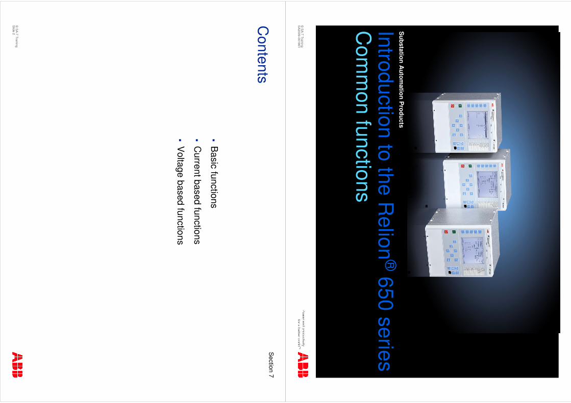
�Function types are identical in the 650 series
�B
asic functions
�S
ystem
�A
pplication/Configuration
�Testing/C
omm
issioning
�Logic
�C
ontrol
�M
onitor
�C
urrent based functions
�V
oltage based functions
�Frequency based functions
Com
mon functions
Relion®
650series
©S
A-T Training
Slide 4
Section
7
Basic IE
D functions
Relion®
650series
System
�S
elf supervision with internal event list
�Tim
e synchronization –S
NTP
, DN
P and/or IR
IG-B
�Term
inal identifiers –N
ame and num
ber: Station, O
bject and Unit
�P
roduct id –P
roduct Type, Firmw
are, Serial N
o, Order N
o, Production
date, etc.
�A
uthority handling –S
afeguards access of the IED
�D
enial of service –P
reventing heavy Ethernet netw
ork traffic to influence IE
D functionality
©S
A-T Training
Slide 5
Section
7
Basic IE
D functions
Relion®
650series
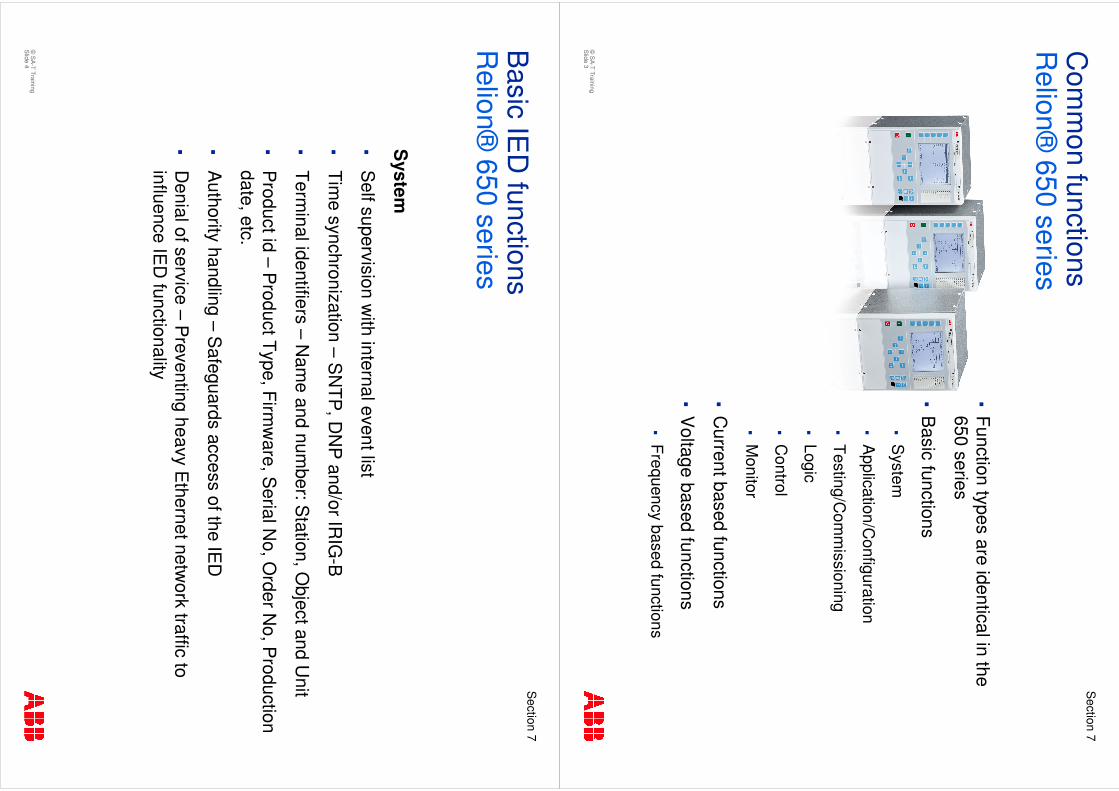
Application/C
onfiguration
�P
rimary system
values –Frequency and phase rotation
�S
etting group handling –4 groups
�S
ignal matrix for analog inputs –
Interface between S
ignal matrix and
Application configuration
�G
lobal base values –6 sets of base voltage, current and apparent
power
Testing/Com
missioning
�Test m
ode functionality –Testing selected functions
�C
hange lock function –B
locking of configuration
�Test outputs -Forcing of binary signals
©S
A-T Training
Slide 6
Section
7
Basic functions –
Logic functions
16B
oolean to Integer conversion
16Integer to B
oolean conversion16
Integerto Boolean
conversionw
ith LN
representation
16 12
11
1
Boolean to Integer conversion w
ith LN
representation
Trip matrix logic
23
21
1Tripping logic
A07 2*OLTC
A05 3W
A01 2W
A07 BC AB
A02 AB
A01 A
A05 Moh
A01 Quad
Logic
RE
L650R
EC
650R
ET650
©S
A-T Training
Slide 7
Section
7
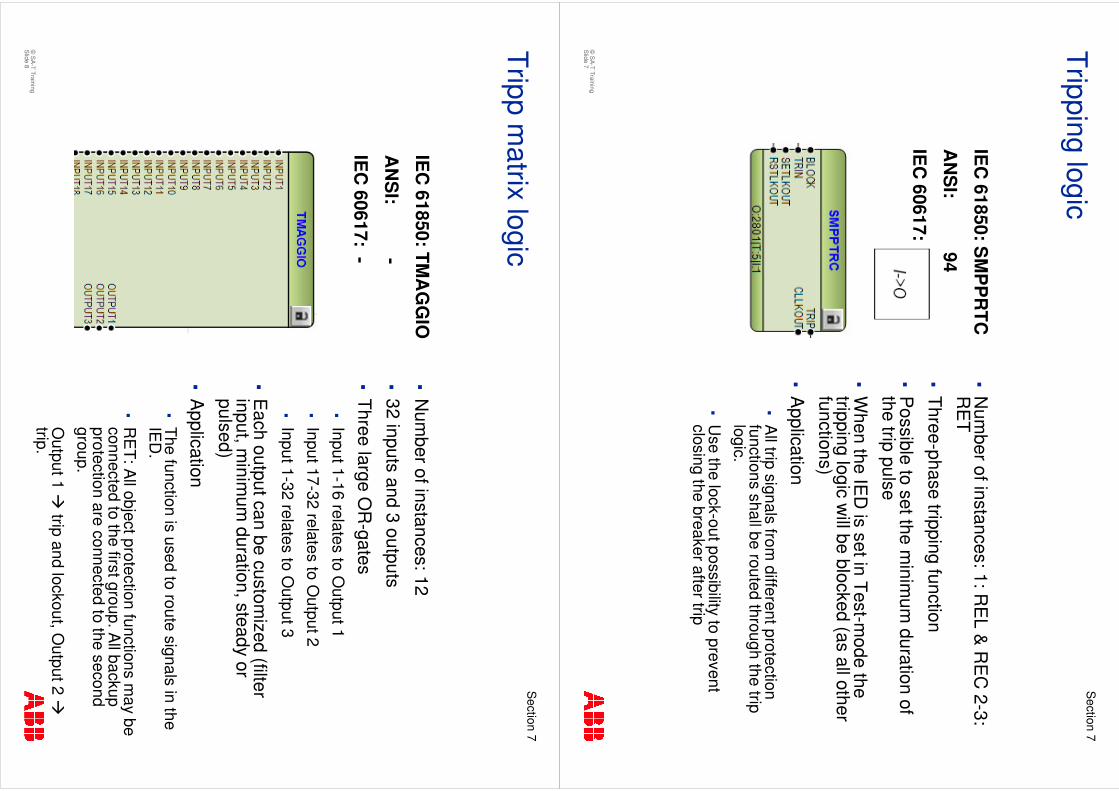
�N
umber of instances: 1: R
EL &
RE
C 2-3:
RE
T
�Three-phase tripping function
�P
ossible to set the minim
um duration of
the trip pulse
�W
hen the IED
is set in Test-mode the
tripping logic will be blocked (as all other
functions)
�A
pplication�
All trip signals from
different protection functions shall be routed through the trip logic.
�U
se the lock-out possibility to prevent closing the breaker after trip
Tripping logic
IEC
61850: SM
PP
RTC
AN
SI:
94
IEC
60617:
©S
A-T Training
Slide 8
Section
7
�N
umber of instances: 12
�32 inputs and 3 outputs
�Three large O
R-gates
�Input 1-16 relates to O
utput 1
�Input 17-32 relates to O
utput 2
�Input 1-32 relates to O
utput 3
�E
ach output can be customized (filter
input, minim
um duration, steady or
pulsed)
�A
pplication�
The function is used to route signals in the IE
D.
�R
ET: A
ll object protection functions may be
connected to the first group. All backup
protection are connected to the second group.
Output 1 �
trip and lockout, Output 2 �
trip.
Tripp matrix logic
IEC
61850: TMA
GG
IO
AN
SI:
-
IEC
60617: -
©S
A-T Training
Slide 9
Section
7
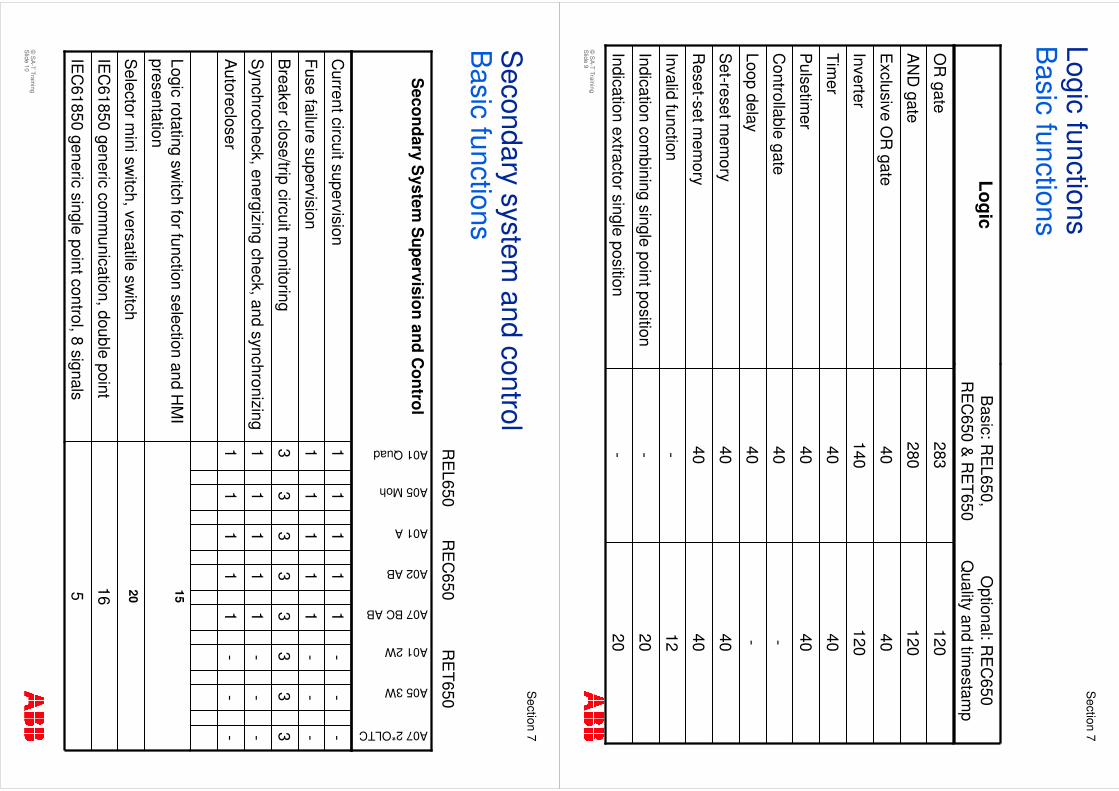
Logic functionsB
asic functions
4040
Set-reset m
emory
4040
Reset-set m
emory
12-
Invalid function
20 20 - - 40 40
120
40
120
120
- - 40 40 40 40
140
40
280
283
Indication extractor single position
Indication combining single point position
Loop delay
Controllable gate
Pulsetim
er
Timer
Inverter
Exclusive O
R gate
AN
D gate
OR
gate
Optional: R
EC
650 Q
ualityand tim
estamp
Basic: R
EL650,
RE
C650 &
RE
T650Logic
©S
A-T Training
Slide 10
Section
7
Secondary system
and controlB
asic functions
16IE
C61850 generic com
munication, double point
5 20 15
1 1 3 1 1
1 1 3 1 1
1 1 3 1 1
IEC
61850 generic single point control, 8 signals
Selector m
ini switch, versatile sw
itch
Logic rotating switch for function selection and H
MI
presentation
--
-1
1A
utorecloser
--
-1
1S
ynchrocheck, energizing check, and synchronizing
33
33
3B
reaker close/trip circuit monitoring
--
-1
1Fuse failure supervision
--
-1
1C
urrent circuit supervision
A07 2*OLTC
A05 3W
A01 2W
A07 BC AB
A02 AB
A01 A
A05 Moh
A01 Quad
Secondary S
ystem S
upervision and Control
RE
L650R
EC
650R
ET650
©S
A-T Training
Slide 11
Section
7
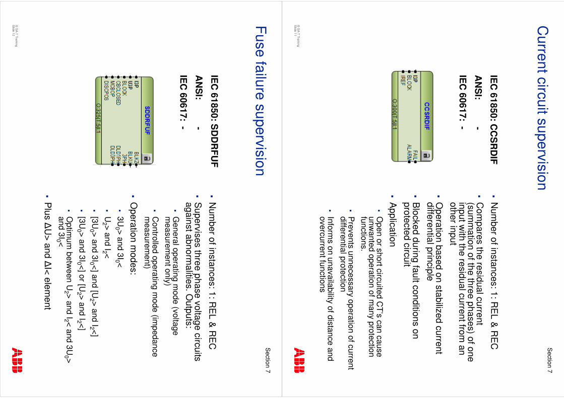
�N
umber of instances: 1: R
EL &
RE
C
�C
ompares the residual current
(summ
ation of the three phases) of one input w
ith the residual current from an
other input
�O
peration based on stabilized current differential principle
�B
locked during fault conditions on protected circuit
�A
pplication�
Open or short circuited C
T’s can cause unw
anted operation of many protection
functions.
�P
revents unnecessary operation of current differential protection
�Inform
s on unavailability of distance and overcurrent functions
Current circuit supervision
IEC
61850: CC
SR
DIF
AN
SI:
-
IEC
60617: -
©S
A-T Training
Slide 12
Section
7
�N
umber of instances: 1: R
EL &
RE
C
�S
upervises three phase voltage circuits against abnorm
alities. Outputs:
�G
eneral operating mode (voltage
measurem
ent only)
�C
ontrolled operating mode (im
pedance m
easurement)
�O
peration modes:
�3U
0 > and 3I0 <
�U
2 > and I2 <
�[3U
0 > and 3I0 <] and [U2 > and I2 <]
�[3U
0 > and 3I0 <] or [U2 > and I2 <]
�O
ptimum
between U
2 > and I2 < and 3U0 >
and 3I0 <
�P
lus �U
> and �I< elem
ent
Fuse failure supervision
IEC
61850: SD
DR
FUF
AN
SI:
-
IEC
60617: -
©S
A-T Training
Slide 13
Section
7
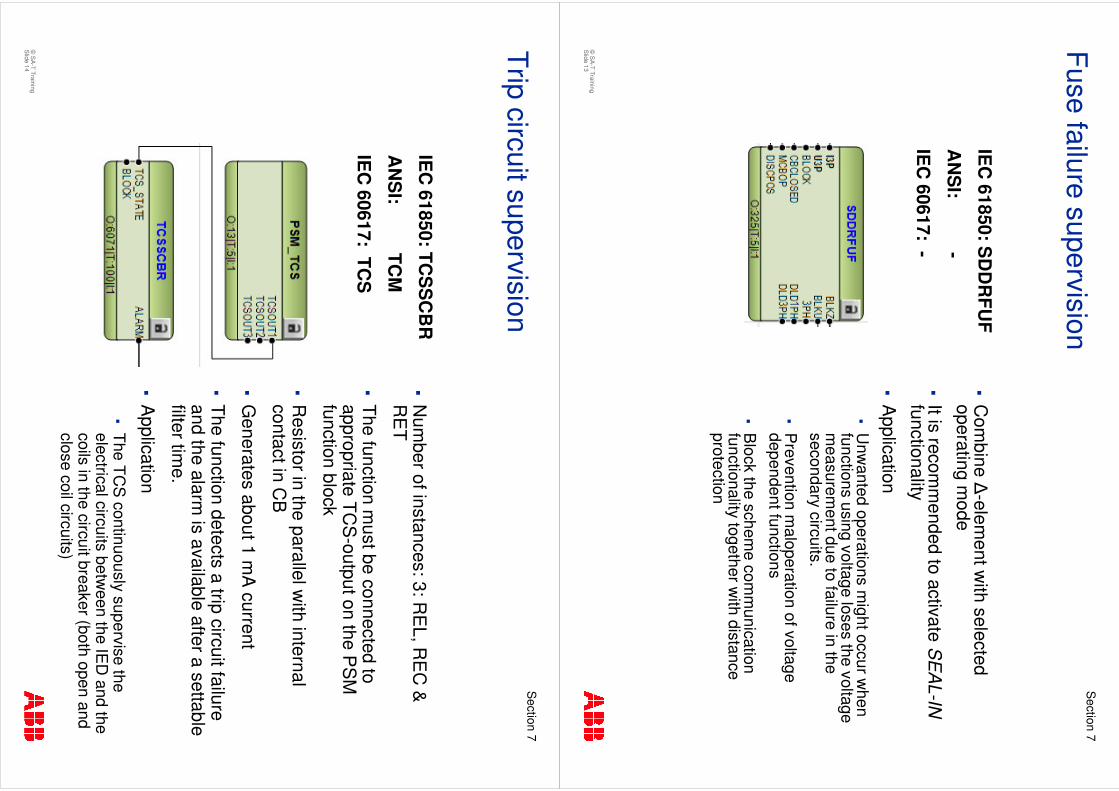
�C
ombine �
-element w
ith selected operating m
ode
�It is recom
mended to activate S
EA
L-IN
functionality
�A
pplication�
Unw
anted operations might occur w
hen functions using voltage loses the voltage m
easurement due to failure in the
secondary circuits.
�P
revention maloperation
of voltage dependent functions
�B
lock the scheme com
munication
functionality together with distance
protection
Fuse failure supervision
IEC
61850: SD
DR
FUF
AN
SI:
-
IEC
60617: -
©S
A-T Training
Slide 14
Section
7
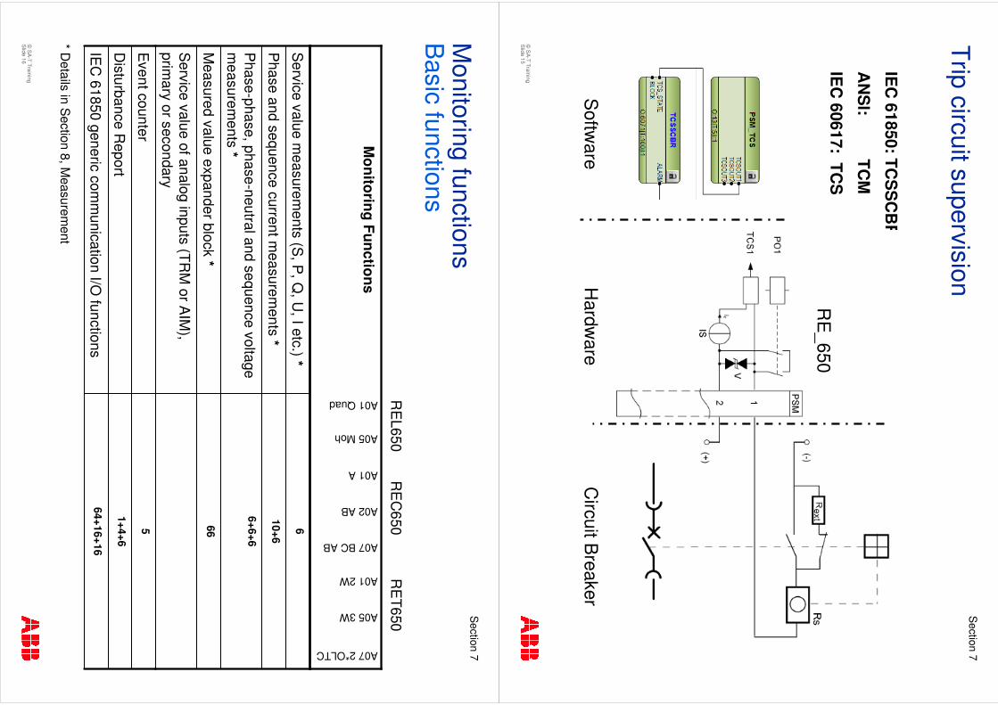
�N
umber of instances: 3: R
EL, R
EC
&
RE
T
�The function m
ust be connected to appropriate TC
S-output on the P
SM
function block
�R
esistor in the parallel with internal
contact in CB
�G
enerates about 1 mA
current
�The function detects a trip circuit failure and the alarm
is available after a settable filter tim
e.
�A
pplication�
The TCS
continuously supervise the electrical circuits betw
een the IED
and the coils in the circuit breaker (both open and close coil circuits)
Trip circuit supervision
IEC
61850: TCS
SC
BR
AN
SI:
TCM
IEC
60617: TCS
©S
A-T Training
Slide 15
Section
7
Trip circuit supervision
IEC
61850: TCS
SC
BR
AN
SI:
TCM
IEC
60617: TCS
RE
_650
Circuit B
reakerH
ardware
Softw
are
©S
A-T Training
Slide 16
Section
7
Monitoring functions
Basic functions
64+16+16
1+4+6
5 66
6+6+6
10+6
6
IEC
61850 generic comm
unication I/O functions
Disturbance R
eport
Event counter
Service value of analog inputs (TR
M or A
IM),
primary or secondary
Measured value expander block *
Phase-phase, phase-neutral and sequence voltage
measurem
ents *
Phase and sequence current m
easurements *
Service value m
easurements (S
, P, Q
, U, I etc.) *
A07 2*OLTC
A05 3W
A01 2W
A07 BC AB
A02 AB
A01 A
A05 Moh
A01 Quad
Monitoring Functions
RE
L650R
EC
650R
ET650
* Details in S
ection 8, Measurem
ent
©S
A-T Training
Slide 17
Section
7
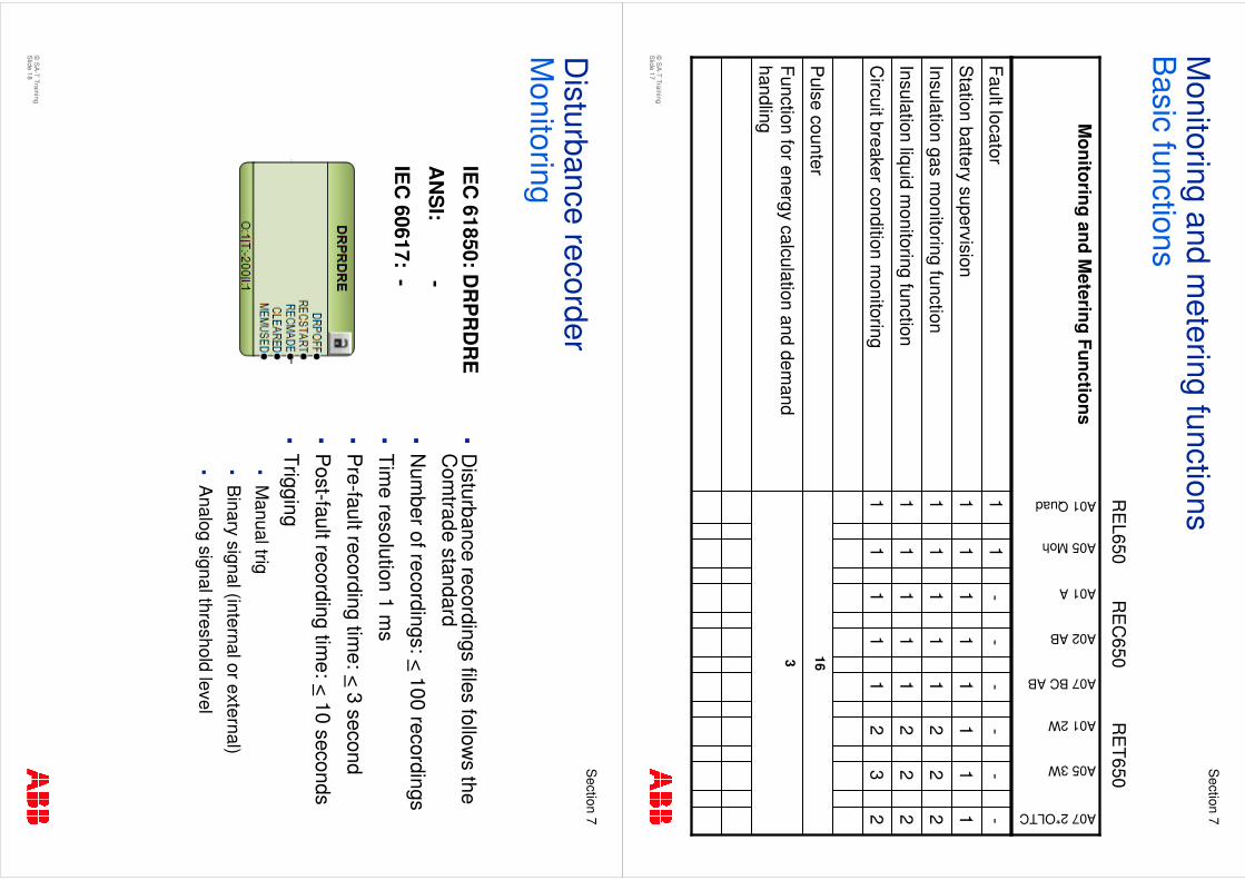
Monitoring and m
etering functionsB
asic functions
3 16
1 1 1 1 1
1 1 1 1 1
1 1 1 1 -
Function for energy calculation and demand
handling
Pulse counter
23
21
1C
ircuit breaker condition monitoring
22
21
1Insulation liquid m
onitoring function
22
21
1Insulation gas m
onitoring function
11
11
1S
tation battery supervision
--
--
-Fault locator
A07 2*OLTC
A05 3W
A01 2W
A07 BC AB
A02 AB
A01 A
A05 Moh
A01 Quad
Monitoring and M
etering Functions
RE
L650R
EC
650R
ET650
©S
A-T Training
Slide 18
Section
7
�D
isturbance recordings files follows the
Com
trade standard
�N
umber of recordings: <
100 recordings
�Tim
e resolution 1 ms
�P
re-fault recording time: <
3 second
�P
ost-fault recording time: <
10 seconds
�Trigging
�M
anual trig
�B
inary signal (internal or external)
�A
nalog signal threshold level
Disturbance recorder
Monitoring
IEC
61850: DR
PR
DR
E
AN
SI:
-
IEC
60617: -
©S
A-T Training
Slide 19
Section
7
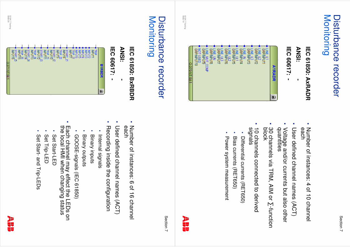
�N
umber of instances: 4 of 10 channel
each
�U
ser defined channel names (A
CT)
�V
oltage and/or currents but also other quantities
�30 channels via TR
M, A
IM or �
-function block
�10 channels connected to derived signals
�D
ifferential currents (RE
T650)
�B
ias currents (RE
T650)
�P
ower system
measurem
ent
Disturbance recorder
MonitoringIE
C 61850: A
xRA
DR
AN
SI:
-
IEC
60617: -
©S
A-T Training
Slide 20
Section
7
�N
umber of instances: 6 of 16 channel
each
�U
ser defined channel names (A
CT)
�R
ecording inside the configuration�
Internal signals
�B
inary inputs
�B
inary outputs
�G
OO
SE
-signals (IEC
61850)
�E
ach channel may effect the LE
Ds
on the local H
MI w
hen changing status�
Set S
tart-LED
�S
et Trip-LED
�S
et Start-and Trip-LE
Ds
Disturbance recorder
Monitoring
IEC
61850: BxR
BD
R
AN
SI:
-
IEC
60617: -
©S
A-T Training
Slide 21
Section
7
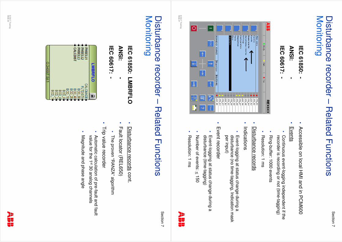
�A
ccessible on local HM
I and in PC
M600
�E
vents
�C
ontinuous event-logging independent if the recorder is recording or not (tim
e-tagging)
�R
ing-buffer: 1000 events
�R
esolution: 1 ms
�D
isturbance records
�Indications
�E
vent-logging at status change during a disturbance (no tim
e-tagging, Indication mask
per input)
�E
vent recorder
�E
vent-logging at status change during a disturbance (tim
e-tagging)
�N
umber of events: <
150
�R
esolution: 1 ms
Disturbance recorder –
Related Functions
Monitoring
IEC
61850: -
AN
SI:
-
IEC
60617: -
©S
A-T Training
Slide 22
Section
7
�D
isturbance recordscont.
�Fault locator (R
EL650)
�The proven “R
AN
ZA”algorithm
�Trip value recorder
�A
utomatic calculation of pre-fault and fault
value for the 1st30 analog channels
�M
agnitude and phase angle
Disturbance recorder –
Related Functions
Monitoring
IEC
61850: LMB
RFLO
AN
SI:
-
IEC
60617: -
©S
A-T Training
Slide 23
Section
7
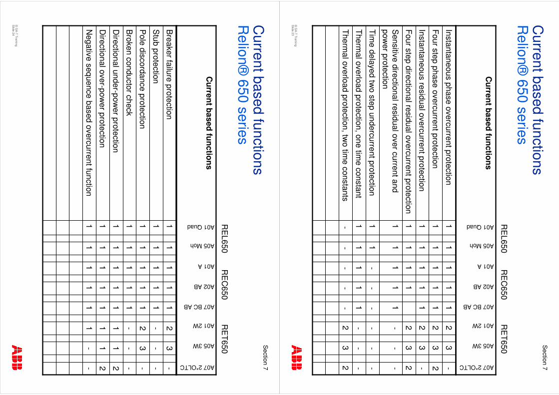
Current based functions
Relion®
650series
- 1 1 1 1 1 1 1
- 1 1 1 1 1 1 1
- 1 - 1 1 1 1 1
23
2-
-Therm
al overload protection, two tim
e constants
--
-1
1Therm
al overload protection, one time constant
--
--
-Tim
e delayed two step undercurrent protection
--
-1
1S
ensitive directional residual over current and pow
er protection
23
21
Four step directional residual overcurrent protection
-3
21
1Instantaneous residual overcurrent protection
23
21
1Four step phase overcurrent protection
-3
21
1Instantaneous phase overcurrent protection
A07 2*OLTC
A05 3W
A01 2W
A07 BC AB
A02 AB
A01 A
A05 Moh
A01 Quad
Current based functions
RE
L650R
EC
650R
ET650
©S
A-T Training
Slide 24
Section
7
Current based functions
Relion®
650series
1 1 1 1 1 1 1
1 1 1 1 1 1 1
1 1 1 1 1 1 1
--
11
1N
egative sequence based overcurrent function
21
11
1D
irectional over-power protection
21
11
1D
irectional under-power protection
--
-1
1B
roken conductor check
-3
21
1P
ole discordance protection
--
-1
1S
tub protection
-3
21
1B
reaker failure protection
A07 2*OLTC
A05 3W
A01 2W
A07 BC AB
A02 AB
A01 A
A05 Moh
A01 Quad
Current based functions
RE
L650R
EC
650R
ET650
©S
A-T Training
Slide 25
Section
7
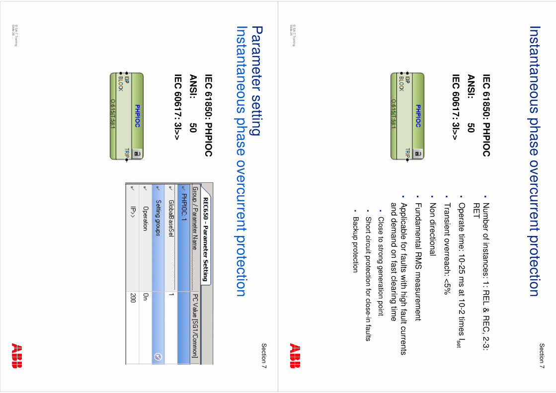
�N
umber of instances: 1: R
EL &
RE
C, 2-3:
RE
T
�O
perate time: 10-25 m
s at 10-2 times Iset
�Transient overreach: <5%
�N
on directional
�Fundam
ental RM
S m
easurement
�A
pplicable for faults with high fault currents
and demand on fast clearing tim
e
�C
lose to strong generation point
�S
hort circuit protection for close-in faults
�B
ackup protection
Instantaneous phase overcurrent protection
IEC
61850: PH
PIO
C
AN
SI:
50
IEC
60617: 3I>>
©S
A-T Training
Slide 26
Section
7
Param
eter settingInstantaneous phase overcurrent protection
IEC
61850: PH
PIO
C
AN
SI:
50
IEC
60617: 3I>>
©S
A-T Training
Slide 27
Section
7
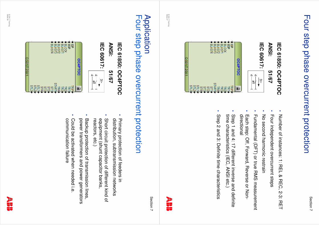
�N
umber of instances: 1: R
EL &
RE
C, 2-3: R
ET
�Four independent overcurrent steps
�N
o second harmonic restrain
�Fundam
ental (DFT) or true R
MS
measurem
ent
�E
ach step: Off, Forw
ard, Reverse or N
on-directional
�S
tep 1 and 4: 17 different inverse and definite tim
e characteristics (IEC
, AN
SI etc.)
�S
tep 2 and 3: Definite tim
e characteristics
Four step phase overcurrent protection
IEC
61850: OC
4PTO
C
AN
SI:
51/67
IEC
60617:
©S
A-T Training
Slide 28
Section
7
�P
rimary protection of feeders in
distribution, subtransmission
networks
�S
hort circuit protection of different kind of equipm
ent (shunt capacitor banks, reactors, etc.)
�B
ackup protection of transmission lines,
power transform
ers and power generators
�C
ould be activated when needed i.e.
comm
unication failure
Application
Four step phase overcurrent protection
IEC
61850: OC
4PTO
C
AN
SI:
51/67
IEC
60617:
©S
A-T Training
Slide 29
Section
7
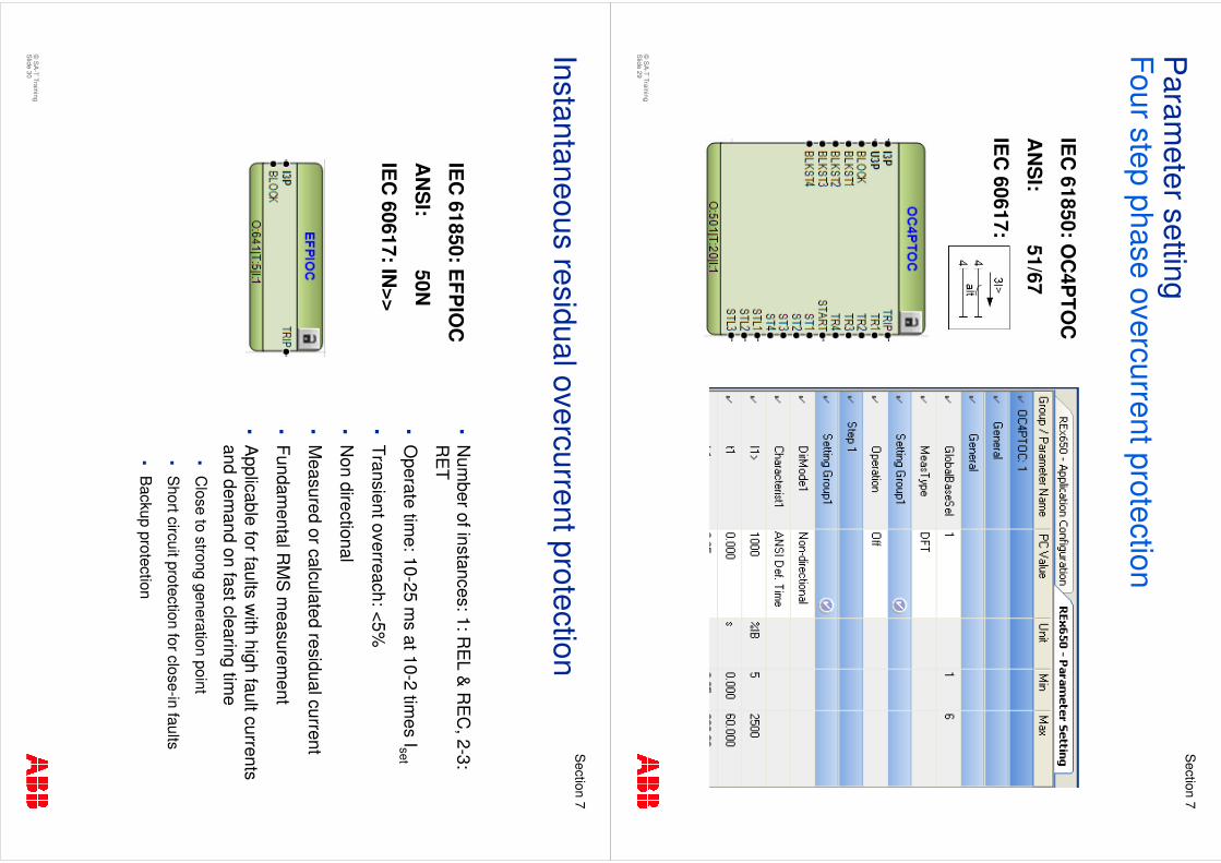
Param
eter settingFour step phase overcurrent protection
IEC
61850: OC
4PTO
C
AN
SI:
51/67
IEC
60617:
©S
A-T Training
Slide 30
Section
7
�N
umber of instances: 1: R
EL &
RE
C, 2-3:
RE
T
�O
perate time: 10-25 m
s at 10-2 times Iset
�Transient overreach: <5%
�N
on directional
�M
easured or calculated residual current
�Fundam
ental RM
S m
easurement
�A
pplicable for faults with high fault currents
and demand on fast clearing tim
e
�C
lose to strong generation point
�S
hort circuit protection for close-in faults
�B
ackup protection
Instantaneous residual overcurrent protection
IEC
61850: EFP
IOC
AN
SI:
50N
IEC
60617: IN>>
©S
A-T Training
Slide 31
Section
7
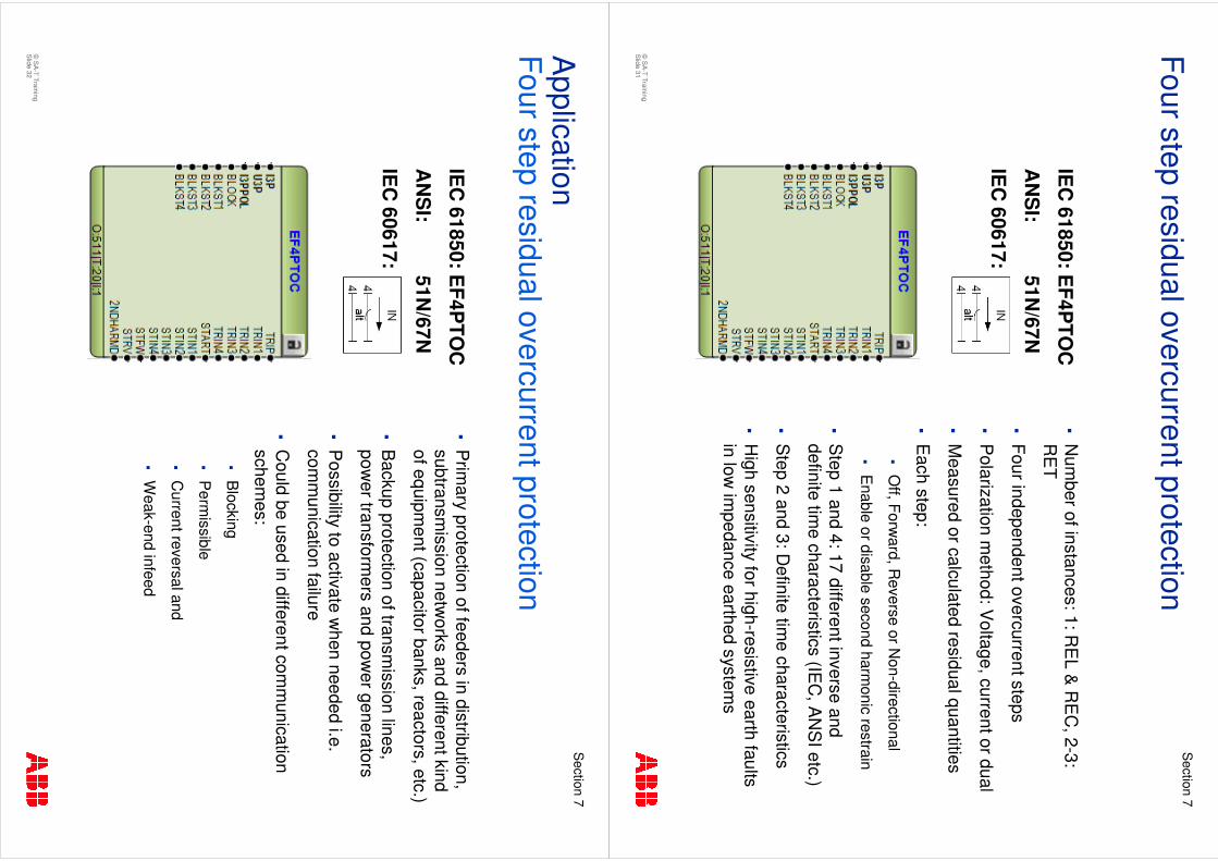
�N
umber of instances: 1: R
EL &
RE
C, 2-3:
RE
T
�Four independent overcurrent steps
�P
olarization method: V
oltage, current or dual
�M
easured or calculated residual quantities
�E
ach step:
�O
ff, Forward, R
everse or Non-directional
�E
nable or disable second harmonic restrain
�S
tep 1 and 4: 17 different inverse and definite tim
e characteristics (IEC
, AN
SI etc.)
�S
tep 2 and 3: Definite tim
e characteristics
�H
igh sensitivity for high-resistive earth faults in low
impedance earthed system
s
Four step residual overcurrent protection
IEC
61850: EF4P
TOC
AN
SI:
51N/67N
IEC
60617:
©S
A-T Training
Slide 32
Section
7
�P
rimary protection of feeders in distribution,
subtransmission
networks and different kind
of equipment (capacitor banks, reactors, etc.)
�B
ackup protection of transmission lines,
power transform
ers and power generators
�P
ossibility to activate when needed i.e.
comm
unication failure
�C
ould be used in different comm
unication schem
es:
�B
locking
�P
ermissible
�C
urrent reversal and
�W
eak-end infeed
Application
Four step residual overcurrent protection
IEC
61850: EF4P
TOC
AN
SI:
51N/67N
IEC
60617:
©S
A-T Training
Slide 33
Section
7
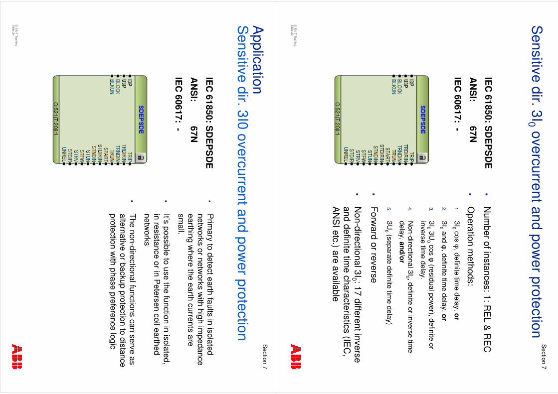
�N
umber of instances: 1: R
EL &
RE
C
�O
peration methods:
1.3I0
cos�
, definite time delay, or
2.3I0
and �, definite tim
e delay, or
3.3I0
3U0
cos�
(residual power), definite or
inverse time delay.
4.N
on-directional 3I0 , definite or inverse time
delay, and/or
5.3U
0(separate definite tim
e delay)
�Forw
ard or reverse
�N
on-directional 3I0 : 17 different inverse and definite tim
e characteristics (IEC
, A
NS
I etc.) are available
Sensitive dir. 3I0
overcurrent and power protection
IEC
61850: SD
EP
SD
E
AN
SI:
67N
IEC
60617: -
©S
A-T Training
Slide 34
Section
7
�P
rimary to detect earth faults in isolated
networks or netw
orks with high im
pedance earthing w
here the earth currents are sm
all.
�It’s possible to use the function in isolated, in resistance or in P
etersen coil earthed netw
orks
�The non-directional functions can serve as alternative or backup protection to distance protection w
ith phase preference logic
Application
Sensitive dir. 3I0 overcurrent and pow
er protection
IEC
61850: SD
EP
SD
E
AN
SI:
67N
IEC
60617: -
©S
A-T Training
Slide 35
Section
7
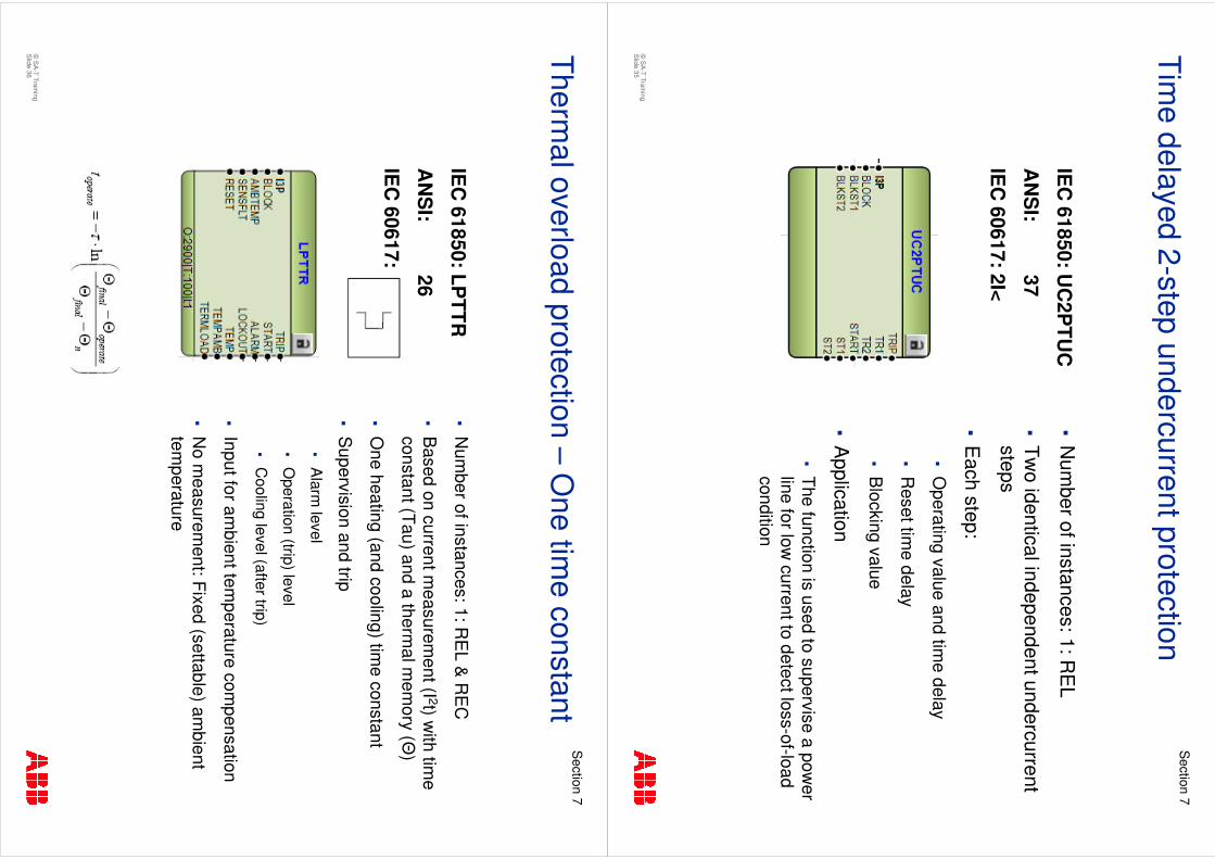
�N
umber of instances: 1: R
EL
�Tw
o identical independent undercurrent steps
�E
ach step:
�O
perating value and time delay
�R
eset time delay
�B
locking value
�A
pplication
�The function is used to supervise a pow
er line for low
current to detect loss-of-load condition
Time delayed 2-step undercurrent protection
IEC
61850: UC
2PTU
C
AN
SI:
37
IEC
60617: 2I<
©S
A-T Training
Slide 36
Section
7
�N
umber of instances: 1: R
EL &
RE
C
�B
ased on current measurem
ent (I 2t) with tim
e constant (Tau) and a therm
al mem
ory (�)
�O
ne heating (and cooling) time constant
�S
upervision and trip
�A
larm level
�O
peration (trip) level
�C
ooling level (after trip)
�Input for am
bient temperature com
pensation
�N
o measurem
ent: Fixed (settable) ambient
temperature
Thermal overload protection –
One tim
e constant
IEC
61850: LPTTR
AN
SI:
26
IEC
60617:
©S
A-T Training
Slide 37
Section
7
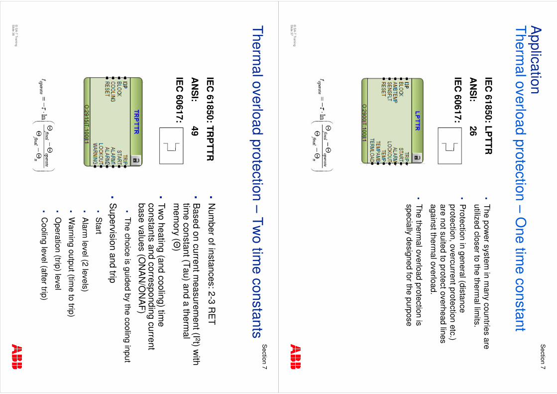
�The pow
er system in m
any countries are utilized closer to the therm
al limits.
�P
rotection in general (distance protection, overcurrent protection etc.) are not suited to protect overhead lines against therm
al overload.
�The therm
al overload protection is specially designed for the purpose
Application
Thermal overload protection –
One tim
e constant
IEC
61850: LPTTR
AN
SI:
26
IEC
60617:
©S
A-T Training
Slide 38
Section
7
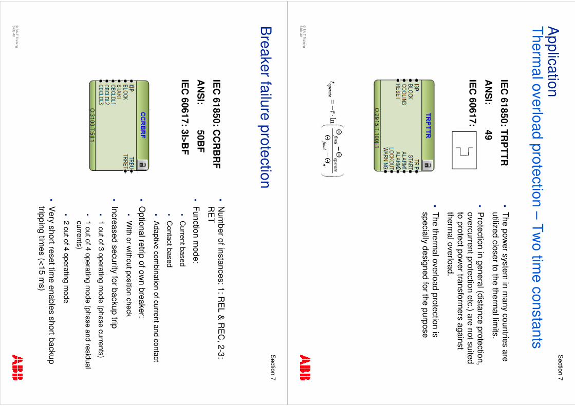
�N
umber of instances: 2-3 R
ET
�B
ased on current measurem
ent (I 2t) with
time constant (Tau) and a therm
al m
emory (�
)
�Tw
o heating (and cooling) time
constants and corresponding current base values (O
NA
N/O
NA
F)�
The choice is guided by the cooling input
�S
upervision and trip�
Start
�A
larm level (2 levels)
�W
arning output (time to trip)
�O
peration (trip) level
�C
ooling level (after trip)
Thermal overload protection –
Two tim
e constants
IEC
61850: TRP
TTR
AN
SI:
49
IEC
60617:
©S
A-T Training
Slide 39
Section
7
�The pow
er system in m
any countries are utilized closer to the therm
al limits.
�P
rotection in general (distance protection, overcurrent protection etc.) are not suited to protect pow
er transformers against
thermal overload.
�The therm
al overload protection is specially designed for the purpose
Application
Thermal overload protection –
Two tim
e constants
IEC
61850: TRP
TTR
AN
SI:
49
IEC
60617:
©S
A-T Training
Slide 40
Section
7
�N
umber of instances: 1: R
EL &
RE
C, 2-3:
RE
T
�Function m
ode:
�C
urrent based
�C
ontact based
�A
daptive combination of current and contact
�O
ptional retripof ow
n breaker: �
With or w
ithout position check
�Increased security for backup trip
�1 out of 3 operating m
ode (phase currents)
�1 out of 4 operating m
ode (phase and residual currents)
�2 out of 4 operating m
ode
�V
ery short reset time enables short backup
tripping times (<15 m
s)
Breaker failure protection
IEC
61850: CC
RB
RF
AN
SI:
50BF
IEC
60617: 3I>BF
©S
A-T Training
Slide 41
Section
7
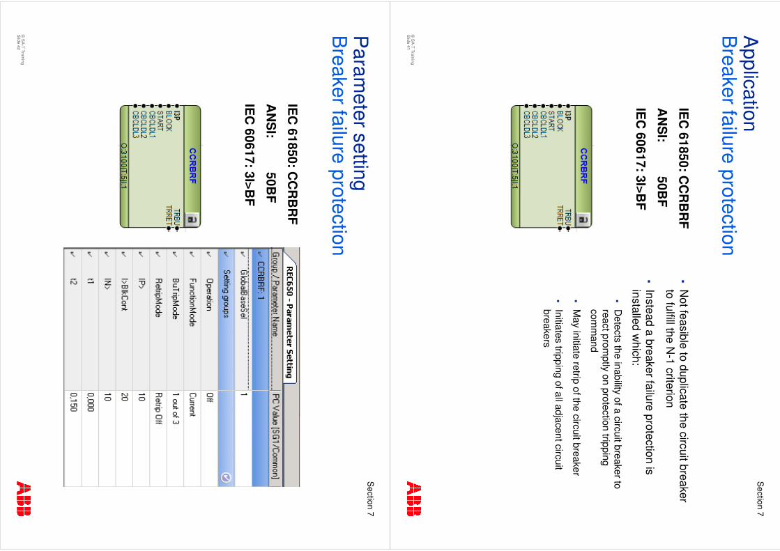
�N
ot feasible to duplicate the circuit breaker to fulfill the N
-1 criterion
�Instead a breaker failure protection is installed w
hich:
�D
etects the inability of a circuit breaker to react prom
ptly on protection tripping com
mand
�M
ay initiate retripof the circuit breaker
�Initiates tripping of all adjacent circuit breakers
Application
Breaker failure protection
IEC
61850: CC
RB
RF
AN
SI:
50BF
IEC
60617: 3I>BF
©S
A-T Training
Slide 42
Section
7
Param
eter settingB
reaker failure protection
IEC
61850: CC
RB
RF
AN
SI:
50BF
IEC
60617: 3I>BF
©S
A-T Training
Slide 43
Section
7
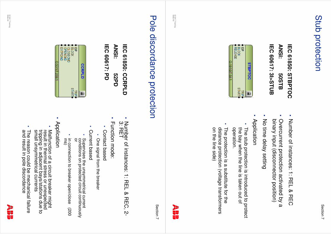
�N
umber of instances: 1: R
EL &
RE
C
�O
vercurrent protection activated by a binary input (disconnector position)
�N
o time delay setting
�A
pplication
�The stub protection is introduced to protect the bay w
hen the line is taken out of operation.
�The protection is a substitute for the distance protection (voltage transform
ers on the line side)
Stub protection
IEC
61850: STB
PTO
C
AN
SI:
50STB
IEC
60617: 3I>STU
B
©S
A-T Training
Slide 44
Section
7
�N
umber of instances: 1: R
EL &
RE
C, 2-
3: RE
T
�Function m
ode:�
Contact based �
One signal from
the breaker
�C
urrent based�
Supervises the unsym
metrical current
conditions on protected circuit continuously or
�in connection to breaker open/close (200 m
s)
�A
pplication�
Malfunction of a circuit breaker m
ight result in therm
al stress or unexpected tripping in adjacent bays/stations due to sm
all unsymm
etrical currents
�The reason could be m
echanical failure and result in pole discordance
Pole discordance protection
IEC
61850: CC
RP
LD
AN
SI:
52PD
IEC
60617: PD
©S
A-T Training
Slide 45
Section
7
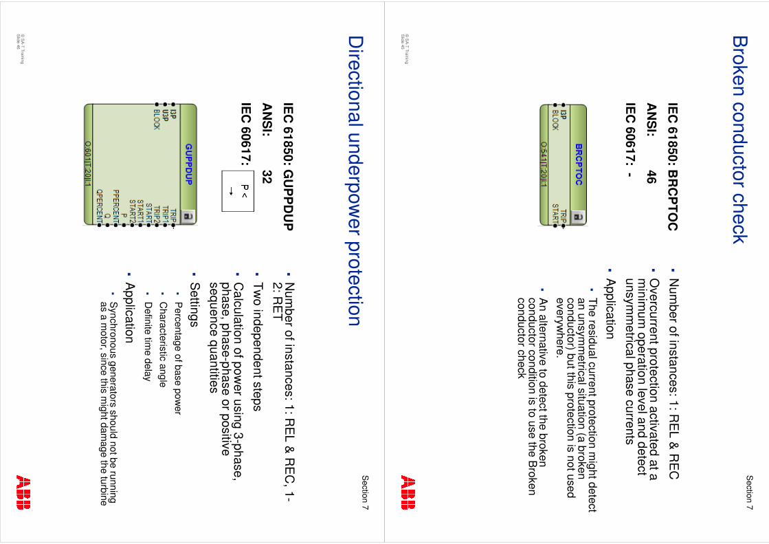
�N
umber of instances: 1: R
EL &
RE
C
�O
vercurrent protection activated at a m
inimum
operation level and detect unsym
metrical phase currents
�A
pplication �
The residual current protection might detect
an unsymm
etrical situation (a broken conductor) but this protection is not used everyw
here.
�A
n alternative to detect the broken conductor condition is to use the B
roken conductor check
Broken conductor check
IEC
61850: BR
CP
TOC
AN
SI:
46
IEC
60617: -
©S
A-T Training
Slide 46
Section
7
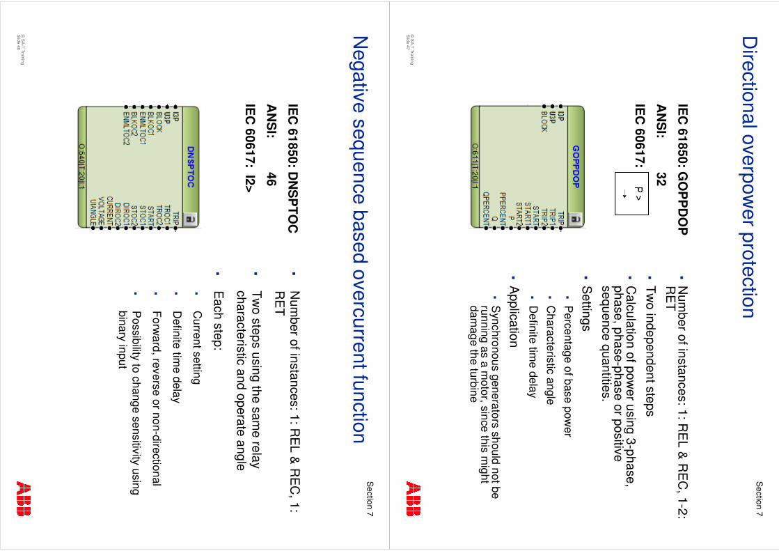
�N
umber of instances: 1: R
EL &
RE
C, 1-
2: RE
T
�Tw
o independent steps
�C
alculation of power using 3-phase,
phase, phase-phase or positive sequence quantities
�S
ettings�
Percentage of base pow
er
�C
haracteristic angle�
Definite tim
e delay
�A
pplication�
Synchronous generators should not be running
as a motor, since this m
ight damage the turbine
Directional underpow
er protection
IEC
61850: GU
PP
DU
P
AN
SI:
32
IEC
60617:
©S
A-T Training
Slide 47
Section
7
�N
umber of instances: 1: R
EL &
RE
C, 1-2:
RE
T
�Tw
o independent steps
�C
alculation of power using 3-phase,
phase, phase-phase or positive sequence quantities.
�S
ettings�
Percentage of base pow
er
�C
haracteristic angle
�D
efinite time delay
�A
pplication�
Synchronous generators should not be
running as a motor, since this m
ight dam
age the turbine
Directional overpow
er protection
IEC
61850: GO
PP
DO
P
AN
SI:
32
IEC
60617:
©S
A-T Training
Slide 48
Section
7
�N
umber of instances: 1: R
EL &
RE
C, 1:
RE
T
�Tw
o steps using the same relay
characteristic and operate angle
�E
ach step:
�C
urrent setting
�D
efinite time delay
�Forw
ard, reverse or non-directional
�P
ossibility to change sensitivity using binary input
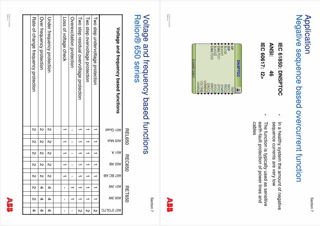
Negative sequence based overcurrent function
IEC
61850: DN
SP
TOC
AN
SI:
46
IEC
60617: I2>
©S
A-T Training
Slide 49
Section
7
�In a healthy system
the amount of negative
sequence currents are very low
�The function is typically used as sensitive earth-fault protection of pow
er lines and cables
Application
Negative sequence based overcurrent function
IEC
61850: DN
SP
TOC
AN
SI:
46
IEC
60617: I2>
©S
A-T Training
Slide 50
Section
7
Voltage and frequency based functions
Relion®
650series
2 2 2 1 - 1 1 1
2 2 2 1 - 1 1 1
2 2 2 1 - 1 1 1
42
22
2R
ate-of-change frequency protection
44
42
2O
ver frequency protection
44
42
2U
nder frequency protection
--
-1
1Loss of voltage check
-1
1-
-O
verexcitation protection
21
11
1Tw
o step residual overvoltage protection
21
11
1Tw
o step overvoltage protection
21
11
1Tw
o step undervoltage protection
A07 2*OLTC
A05 3W
A01 2W
A07 BC AB
A02 AB
A01 A
A05 Moh
A01 Quad
Voltage and frequency based functions
RE
L650R
EC
650R
ET650

©S
A-T Training
Slide 51
Section
7
�N
umber of instances: 1: R
EL &
RE
C, 1-2:
RE
T
�Tw
o steps using the same voltage input
�P
hase-N, D
FT or RM
S
�P
hase-Phase, D
FT or RM
S
�For each step: 1, 2 or 3 out of 3 low
voltages
�S
tep 1 definite or inverse characteristic:�
Definite tim
e delay
�Inverse characteristic A
or B
�S
tep 2: Definite tim
e delay
�A
pplication�
Undervoltages
may occur in pow
er system
s and action may be required.
�The function can be used for voltage supervision and control
Two step undervoltage protection
IEC
61850: UV
2PTU
V
AN
SI:
27
IEC
60617: 3U<
©S
A-T Training
Slide 52
Section
7
�N
umber of instances: 1: R
EL &
RE
C, 1-2:
RE
T
�Tw
o steps using the same voltage input
�P
hase-N, D
FT or RM
S
�P
hase-Phase, D
FT or RM
S
�For each step: 1, 2 or 3 out of 3 high voltages
�S
tep 1 definite or inverse characteristic:�
Definite tim
e delay
�Inverse characteristic A
, B or C
�S
tep 2: Definite tim
e delay
�A
pplication�
Overvoltages m
ay occur in power system
s and action m
ay be required.
�The function can be used for voltage supervision and control.
Two step overvoltage protection
IEC
61850: OV
2PTO
V
AN
SI:
59
IEC
60617: 3U>
©S
A-T Training
Slide 53
Section
7
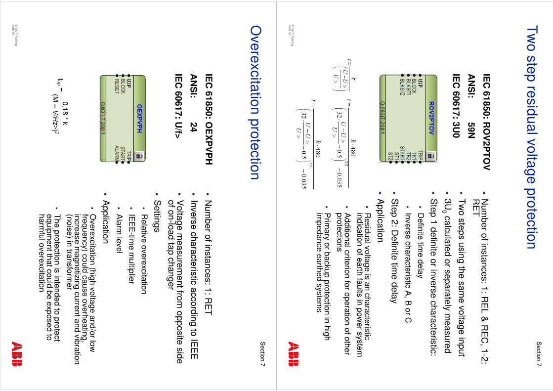
�N
umber of instances: 1: R
EL &
RE
C, 1-2:
RE
T
�Tw
o steps using the same voltage input
�3U
0calculated or separately m
easured
�S
tep 1 definite or inverse characteristic:�
Definite tim
e delay
�Inverse characteristic A
, B or C
�S
tep 2: Definite tim
e delay
�A
pplication�
Residual voltage is an characteristic
indication of earth faults in power system
�A
dditional criterion for operation of other protections
�P
rimary or backup protection in high
impedance earthed system
s
Two step residual voltage protection
IEC
61850: RO
V2P
TOV
AN
SI:
59N
IEC
60617: 3U0
©S
A-T Training
Slide 54
Section
7
�N
umber of instances: 1: R
ET
�Inverse characteristic according to IE
EE
�V
oltage measurem
ent from opposite side
of on-load tap changer
�S
ettings�
Relative overexcitation
�IE
EE
-time m
ultiplier
�A
larm level
�A
pplication�
Overexcitation (high voltage and/or low
frequency) could cause overheating, increase m
agnetizing current and vibration (noise) in transform
er
�The protection is intended to protect equipm
ent that could be exposed to harm
ful overexcitation
Overexcitation protection
IEC
61850: OE
XP
VP
H
AN
SI:
24
IEC
60617: U/f>
©S
A-T Training
Slide 55
Section
7
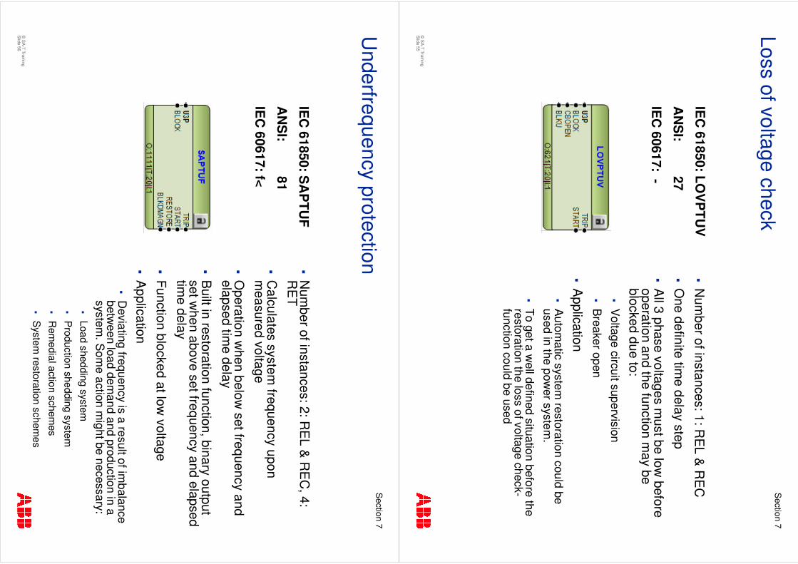
�N
umber of instances: 1: R
EL &
RE
C
�O
ne definite time delay step
�A
ll 3 phase voltages must be low
before operation and the function m
ay be blocked due to:
�V
oltage circuit supervision
�B
reaker open
�A
pplication�
Autom
atic system restoration could be
used in the power system
.
�To get a w
ell defined situation before the restoration the loss of voltage check-function could be used
Loss of voltage check
IEC
61850: LOV
PTU
V
AN
SI:
27
IEC
60617: -
©S
A-T Training
Slide 56
Section
7
�N
umber of instances: 2: R
EL &
RE
C, 4:
RE
T
�C
alculates system frequency upon
measured voltage
�O
peration when below
set frequency and elapsed tim
e delay
�B
uilt in restoration function, binary output set w
hen above set frequency and elapsed tim
e delay
�Function blocked at low
voltage
�A
pplication�
Deviating frequency is a result of im
balance betw
een load demand and production in a
system. S
ome action m
ight be necessary: �
Load shedding system
�P
roduction shedding system
�R
emedial action schem
es
�S
ystem restoration schem
es
Underfrequency protection
IEC
61850: SA
PTU
F
AN
SI:
81
IEC
60617: f<
©S
A-T Training
Slide 57
Section
7
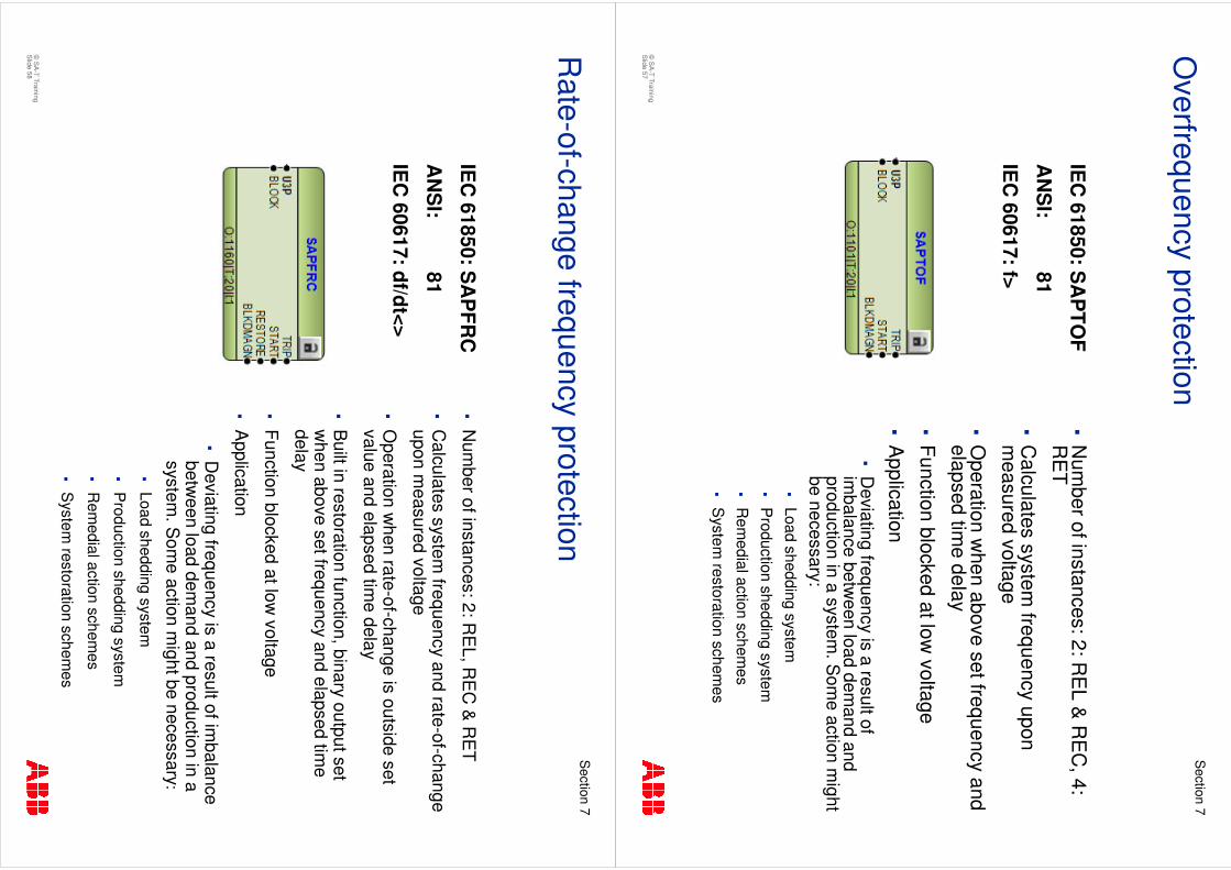
�N
umber of instances: 2: R
EL &
RE
C, 4:
RE
T
�C
alculates system frequency upon
measured voltage
�O
peration when above set frequency and
elapsed time delay
�Function blocked at low
voltage
�A
pplication�
Deviating frequency is a result of
imbalance betw
een load demand and
production in a system. S
ome action m
ight be necessary:
�Load shedding system
�P
roduction shedding system
�R
emedial action schem
es�
System
restoration schemes
Overfrequency protection
IEC
61850: SA
PTO
F
AN
SI:
81
IEC
60617: f>
©S
A-T Training
Slide 58
Section
7
�N
umber of instances: 2: R
EL, R
EC
& R
ET
�C
alculates system frequency and rate-of-change
upon measured voltage
�O
peration when rate-of-change is outside set
value and elapsed time delay
�B
uilt in restoration function, binary output set w
hen above set frequency and elapsed time
delay
�Function blocked at low
voltage
�A
pplication
�D
eviating frequency is a result of imbalance
between load dem
and and production in a system
. Som
e action might be necessary :
�Load shedding system
�P
roduction shedding system
�R
emedial action schem
es
�S
ystem restoration schem
es
Rate-of-change frequency protection
IEC
61850: SA
PFR
C
AN
SI:
81
IEC
60617: df/dt<>

©S
A-T Training
Slide 59
Section
7


![CRNM - Telecoms Report Revised [Sep 07]](https://img.pdfslide.us/doc/110x75/58a347e11a28ab62248b5e33/crnm-telecoms-report-revised-sep-07.jpg)