Embed Size (px)
DESCRIPTION
BTS over RAN sys
Citation preview
1 © NOKIA 2001 RAN Transmission.ppt / BTS PCT
WCDMA BTS as Transmission Hub
Towards RNC
SiteSite
Site
Site
WCDMA BTS
2 © NOKIA 2001 RAN Transmission.ppt / BTS PCT
Integrated & Stand-alone AXC
AXU IFU
IFU
IFU
IFU
IFU
• AXC (ATM Cross Connect) is the Integrated ATM Transmission Node of the Nokia WCDMA Basestationand a Stand-alone ATM Transmission Network Element. The Integrated AXC supported 4 IFU while S-AXC support 5 IFU. The S-AXC can be installed in a standard ETSI or 19-inch rack and co-located with the BTS
S-AXC needed:
• In Japan, providing at the RNC site interface conversion for the JT2 and STM-0 interfaces
- No JT2 and STM-0 interfaces are available for the RNC at the moment
• Provide additional slots for interface units at WCDMA BTS sites
- At some sites the available 5 slots for interface units in the BTS integrated AXC may not be sufficient
• A Hub for grooming/concentrating WCDMA traffic at a site without WCDMA BTS
3 © NOKIA 2001 RAN Transmission.ppt / BTS PCT
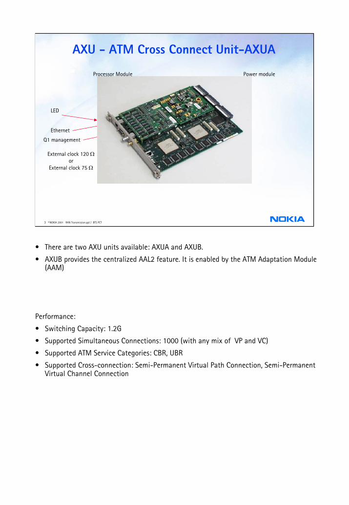
AXU - ATM Cross Connect Unit-AXUA
Power moduleProcessor Module
LED
Ethernet
Q1 management
External clock 120 Ωor
External clock 75 Ω
• There are two AXU units available: AXUA and AXUB.
• AXUB provides the centralized AAL2 feature. It is enabled by the ATM Adaptation Module (AAM)
Performance:
• Switching Capacity: 1.2G
• Supported Simultaneous Connections: 1000 (with any mix of VP and VC)
• Supported ATM Service Categories: CBR, UBR
• Supported Cross-connection: Semi-Permanent Virtual Path Connection, Semi-Permanent Virtual Channel Connection

4 © NOKIA 2001 RAN Transmission.ppt / BTS PCT
AXU - ATM Cross Connect Unit-AXUB
• AXUB provides the centralized AAL2 feature. It is enabled by the ATM Adaptation Module (AAM)
Performance:
• Switching Capacity: 1.2G
• Supported Simultaneous Connections: 1000 (with any mix of VP and VC)
• Supported ATM Service Categories: CBR, UBR
• Supported Cross-connection: Semi-Permanent Virtual Path Connection, Semi-Permanent Virtual Channel Connection
5 © NOKIA 2001 RAN Transmission.ppt / BTS PCT
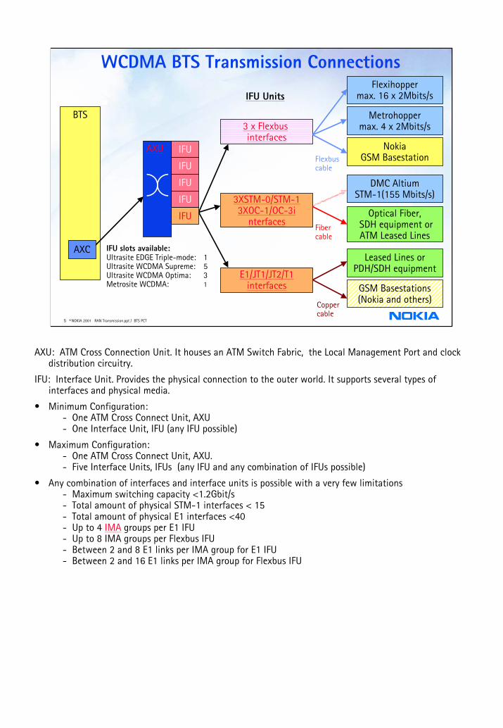
WCDMA BTS Transmission Connections
3 x Flexbusinterfaces
3XSTM-0/STM-13XOC-1/OC-3i
nterfaces
E1/JT1/JT2/T1interfaces
IFU UnitsFlexihopper
max. 16 x 2Mbits/s
Metrohoppermax. 4 x 2Mbits/s
NokiaGSM BasestationFlexbus
cable
DMC AltiumSTM-1(155 Mbits/s)
Optical Fiber,SDH equipment orATM Leased Lines
Fiber cable
Leased Lines orPDH/SDH equipment
GSM Basestations(Nokia and others)Copper
cable
BTS
IFU slots available:Ultrasite EDGE Triple-mode: 1Ultrasite WCDMA Supreme: 5Ultrasite WCDMA Optima: 3Metrosite WCDMA: 1
AXU IFU
IFU
IFU
IFU
IFU
AXC
AXU: ATM Cross Connection Unit. It houses an ATM Switch Fabric, the Local Management Port and clock distribution circuitry.
IFU: Interface Unit. Provides the physical connection to the outer world. It supports several types of interfaces and physical media.
• Minimum Configuration:- One ATM Cross Connect Unit, AXU- One Interface Unit, IFU (any IFU possible)
• Maximum Configuration:- One ATM Cross Connect Unit, AXU.- Five Interface Units, IFUs (any IFU and any combination of IFUs possible)
• Any combination of interfaces and interface units is possible with a very few limitations- Maximum switching capacity <1.2Gbit/s- Total amount of physical STM-1 interfaces < 15- Total amount of physical E1 interfaces <40- Up to 4 IMA groups per E1 IFU- Up to 8 IMA groups per Flexbus IFU- Between 2 and 8 E1 links per IMA group for E1 IFU- Between 2 and 16 E1 links per IMA group for Flexbus IFU

6 © NOKIA 2001 RAN Transmission.ppt / BTS PCT
AXC Transmission Interface UnitsIFUA (IFU 8P1 balanced)
• 8 x E1/T1/JT1 interfaces (110 Ω / 120 Ω balanced TQ-connectors )
• with Inverse Multiplexing for ATM (IMA)
• unstructured CES
• structured CES
• fractional Interface(E1/T1/JT1)
IFUB (IFU 4P2)
• 4 x JT2 interfaces(75 Ω BT-43 connectors)
• with IMA
IFUA
CES to map TDM traffic in TDM cells
• complete E1/T1/JT1 frame transported in ATM cells (unstructured)
• Fractional E1/T1/JT1, only TDM timeslots transported withinATM cells
CES is implemented in RAN 2.0(C2.0 for AXC)
IFUB
JT2: 4JT1(6.312M)
Fractional Interface(E1/T1/JT1)
each of the interfaces can be configured as
• ATM over full E1/T1/JT1
• fractional E1/T1/JT1 (timeslots not used byATM traffic could be filled up with TDM trafficby external cross-connections

7 © NOKIA 2001 RAN Transmission.ppt / BTS PCT
AXC Transmission Interface UnitsIFUC (IFU3S)• 3 x SDH optical interfaces, which can be configured
independently as:
STM-0 (51.8 Mbit/s) or STM-1 (155.5 Mbit/s)OC-1(51.8 Mbit/s) or OC-3 (155.5 Mbit/s)
IFUD (IFU8P1 coaxial)• 8 x E1 interfaces
(75 Ω unbalanced BT 43-connectors )• IMA Supported• Unstructured CES• Structured CES• Fractional interface(E1)
IFU3S: 3 x SDH optical interfaces, which can be configured as (mixed configuration supported):
- STM-0 (VC-3 )Optical Intra-officeOptical Short-Haul
- STM-1 (VC-4,)As in STM-0
- OC-1 American SDH(American Standard)- OC-3 American SDH(American Standard)
STM-0 Physical Interface
Network elements:
RNC - 4 interfaces per plug-in-unit (Supported in RAN1.5)
BTS - 3 interfaces per IFU (Supported in RAN1)
OC-1 American SDH in RAN2.0
Bit rate: 51.84 Mbit/s
Used connector: optical, LC –type
ATM Mapped into VC-3,
STM-1 Physical Interface
Network elements:
RNC - 4 interfaces per plug-in-unit (Supported in RAN1.5)
BTS - 3 interfaces per IFU (Supported in RAN1)
Bit rate: 155.52 Mbit/s
Used connector: optical, LC –type
ATM Mapped into VC-4,

8 © NOKIA 2001 RAN Transmission.ppt / BTS PCT
FLEXBUS Interface for Radios
FIU19"
BS Site
BTS
E1
BS Site
BTS
Flexbus(16 x 2M)
Flexbus(16 x 2M)
RAN1 Solution
RAN 1 Phase 1.5 solution:FIU19" removed, Flexbus IFU unit installed directly into the BTS
RAN1 Phase 1.5Solution
• RAN 1 Phase 1.5 / AXC Flexbus: For ETSI market, a Flexbus interface is introduced into AXC, enabling direct connection from WCDMA BTS to Nokia FlexiHopper or MetroHopperor Nokia GSM Basestations.
IFU3FB: 3 x Flexbus with IMA. Flexbus capacity up to 16 x E1.
- Connects Nokia microwave radio
- Interconnects Nokia GSM BTS
- Allows combination of 2G (TDM) and 3G (ATM) traffic with a granularity of E1
Flexbus Physical Interface
Network elements:
BTS - 3 interfaces per plug-in-unit
RNC site - Flexbus interface is implemented using Stand-alone AXC or FIU19" equipment
With Flexbus feature BTS connects directly to Nokia Flexi/Metro Hopper
Capacity: max. 16 x 2M (4 x 2M for MetroHopper)
ATM Mapped into n x E1s
ATM Inverse Multiplexing functionality (IMA) within one plug-in-unit
2M crossconnection within one plug-in-unit

9 © NOKIA 2001 RAN Transmission.ppt / BTS PCT
IMA GroupE1/JT1
E1/JT1
E1/JT1
AXCIMA Group
E1/JT1
E1/JT1
E1/JT1
NIP1
Inverse Multiplexing for ATM
Single ATM cell stream from ATM layer
Link # 0
Link # 1
Link # 2
Original ATM cell stream to ATM layer
IMA virtual link
TX direction cells distributed across links in round robin sequenceRX direction cells recombined into single ATM stream
• IMA allows the combining of several physical links (E1 or JT1, ) to one logical link
Maximum 8 IMA links per Group
Max 4 IMAGS on IFUA/D and 8 IMAGs on IFUE

10 © NOKIA 2001 RAN Transmission.ppt / BTS PCT
RNC
WAM
WBTS
WAM
WAM
ATM Connection TableHW VPI VCI
x x x
VCI
x
VPI
x
HW
x
Term-1Term-1Term-1Term-1Term-1Term-1Term-1
1111111
33343536373839
Router AXC
NetAct
C-NBAPTCP/IP
D-NBAPUP
C-NBAPTCP/IP
UP
AAL2 sig
C-NBAPTCP/IP
D-NBAPUPUP
AAL2 sig
D-NBAPUPUP
AAL2 sig
AXU
50515253545556
5555555
Term-2Term-2Term-2Term-2Term-2Term-2Term-2
ATM VPCs
To other BTSs ATM VCCs
WCDMA BTS - RNC Connections
UP
UP
UP
AXC Features
• Virtual Path (VP) & Virtual Channel (VC) ATM Cross Connect
• Supports different Transmission Network Topologies like Star, Chain, Tree
• Fully compatible with existing underlying transmission technologies PDH and SDH- Present TDM networks can be used- Existing spare capacity can be used- Existing investments can be preserved- Minimize initial UMTS investments
• Fully compatible with existing ATM transmission networks (if any)
• Supports 3G-PP, Japanese and ETSI/ITU standards.
• Provides Up-to-Date WEB-based Management.
• Switching capacity up to 1.2Gbit/s
• Up to 1000 simultaneous connections
• Supports UNI/NNI format at ATM layer
• Support of different QoS Categories like CBR.1, UBR.1 ,UTR.2 etc.
• Traffic Management Function:
• Connection Admission Control
• Usage Parameter Control
• Traffic Shaping for CBR&UBR connections
• Support of OAM flows
• This picture is only for a example and the real situation will be different according to project

11 © NOKIA 2001 RAN Transmission.ppt / BTS PCT
Iub cross connections in AXC
AXUIFUxslot 2if 1
STM-1 or E1 CIF 1
VCI 120
VPI 1
VCI 56
BTS
WAM 1-0
VCI 72
VCI 40
AXC
VCI 36
VPI 0
CNBAP
AAL2UP
VCI 33
VCI 34
VCI 35
Name ATM interface VPI VP PCR [cells/s]
VCI VC PCR [cells/s]
ATM Interface VPI VP PCR [cells/s]
VCI VC PCR [cells/s]
Service Category
CNBAP CIF 1 0 58726 33 300 Unit 2 Interface 1 1 4528 56 300 CBRDNBAP CIF 1 0 58726 34 150 Unit 2 Interface 1 1 4528 72 150 CBR
AAL2SIG CIF 1 0 58726 35 150 Unit 2 Interface 1 1 4528 40 150 CBRAAL2UP CIF 1 0 58726 36 3618 Unit 2 Interface 1 1 4528 120 3618 CBR
DNBAP
AAL2SIG
12 © NOKIA 2001 RAN Transmission.ppt / BTS PCT
SARRNC
CNBAP
DNBAP
AAL2SIG
AAL2UP
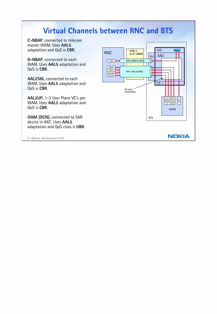
Virtual Channels between RNC and BTS
AXUIFU
CIF-1
BTS
WAM
CNBA
P
DNBA
P
AAL2
SIG
AAL2
UP
STM-1or E1 (IMA)
VC cross connections
C-NBAP, connected to telecom master WAM. Uses AAL5adaptation and QoS is CBR.
D-NBAP, connected to each WAM. Uses AAL5 adaptation and QoS is CBR.
AAL2SIG, connected to each WAM. Uses AAL5 adaptation and QoS is CBR.
AAL2UP, 1-3 User Plane VC’s per WAM. Uses AAL2 adaptation and QoS is CBR.
O&M (DCN), connected to SAR device in AXC. Uses AAL5adaptation and QoS class is UBR.
O&M VPI 0 (DCN to BTS)
VPI 1 (Iub to BTS)
O&
M

13 © NOKIA 2001 RAN Transmission.ppt / BTS PCT
AXC Transmission Example
RNC
3G-SGSN
ATMModule
MSC
RNC
WCDMABTS
WCDMABTS
WCDMABTS
WCDMABTS
S-AXC
S-AXC
IMA(nXE1)STM-1
STM-1STM-1
STM-1STM-1
STM-1
Common MSC / RNC / GPRS Site
IubIurIu-csIu-ps
S-AXCAXU 8 x E1
8 x E18 x E18 x E1
3 x STM-1
Hub Site
IMA(nXE1)
IMA(nXE1)
IMA(nXE1)
IMA(nXE1)
IMA(nXE1)
IMA(nXE1)
IMA(nXE1)
IMA(nXE1)
STM-1

14 © NOKIA 2001 RAN Transmission.ppt / BTS PCT
ATMNokiaUltraSiteWDCMA
BTS
GSMBTS
IubAbis
PDH/SDHNokiaUltraSiteWDCMA
BTS
GSMBTS
IubAbis Share PDH/ SDH Capacity
(RAN1 Phase 1: n x 2M)
(RAN1 Phase 1.5: n x 64k Fractional E1 if)
Share ATM Capacity
RAN2.0 (Unstructed & Structed
Circuit Circuit Emulation)
Both options supported
Combining WCDMA and GSM traffic
TDM
Using external PDH and SDH equipment to Add and Drop different traffic interface(E1,STM-1,T1,…)Nokia's Metrohub, DN2 or the GSM BTS DTRU/TRUA can perform these required cross-connections
ATM traffic starts always with TS1 to TSn and then TSn+1 for TDM. For changing TS a 64 cross-connect necessaryAdvantage: existing GSM traffic does not have to be disturbed.
ATM
Using Circuit Emulation Service to add GSM (TDM) traffic to WCDMA (ATM) trafficDisadvantage: GSM transmission has to be interrupted before connecting it to the WCDMA transmission

15 © NOKIA 2001 RAN Transmission.ppt / BTS PCT
Common TDM transport for GSM and UMTS traffic
RNC
BSC
ETCOMMONTRANSPORTON MICROWAVE
n x E1 or FB from 3G BTS
GSM BTSTRX
TRX
TRX
WSP WSP WSP
3G BTS AXC
...WAM
WSP WSP WSP...WAM
TRUA
IFU
E1 for GSM BTSTRX
TRX
TRX RRIC
Metrohub
n x E1 from 3G BTS
ATMSWITCHIFU

16 © NOKIA 2001 RAN Transmission.ppt / BTS PCT
Common ATM transport for GSM and UMTS traffic
RNC
BSC
ETCOMMONTRANSPORTON MICROWAVE
FB from 3G BTS
GSM BTSTRX
TRX
TRX
WSP WSP WSP
3G BTS AXC
...WAM
WSP WSP WSP...WAM
TRUA
IFU
n x E1 or FB for GSM BTSTRX
TRX
TRX RRI
Stand-aloneAXC
ATMSWITCHIFU

17 © NOKIA 2001 RAN Transmission.ppt / BTS PCT
TDM links with Fractional PDH interface• Physical link can be Fibre, Microwave, leased service, ...• BTS site:
•WCDMA BTS connected to GSM Abis•WCDMA BTS supports ATM over Fractional Interface(E1/T1/JT1)
• BSC/RNC site:•TDM traffic (GSM + WCDMA) separated by TDM cross-connect Hub•Possible, not earlier groomed, Fractional E1 traffic is terminated with a standalone AXC
GSM BTS
WCDMA BTS
TDM link (PDH/SDH)HUB BSC
RNC
Combined Abis and Iub
TDM crossconnect function (n x 64 kbits/s)
Fractional E1 (partly filled) (n x 64 kbits/s)
Fractional E1
Fractional E1
Full E1 Full E1

18 © NOKIA 2001 RAN Transmission.ppt / BTS PCT
Circuit Emulation Service
BTS
WCDMABTS
CES = Circuit Emulation Service
AXC
StdIF
AXC
StdIF
Notes:
1. The link between BTS and BS can be one or more E1/T1 connections. Any of them can be fractional or full E1/T1 frames. Circuit Emulation is using AAL1 conversion and CBR QoS class.
2. At the RNC site shall be a CES Interworking Function which shall be implementedby a standalone AXC.
There can be severalAXC's in the access networkalong the route
This connection can be- one standard E1/T1, also fractional possible- several E1/T1's, also fractional- Flexbus containing E1's as above
RNC/BSC siteBTS/BS site
StdIF
TDMATM
CES byAAL1
RNCAXC
StdIF
BSCStdIF
N
StdIF
CES
Standalone
N x
E1/
T1
Two alternatives:
- Unstructured service is intended to emulate a point-to-point E1 circuit
- Structured service is intended to emulate a point-to-point Fractional E1 circuit
Fully synchronous service because of UMTS requirements
No Statistical Multiplexing Gain because of its CBR nature
Unstructured circuit emulation service might be used to perform E1 TDM cross connection within AXC, e.g. from one E1 to Flexbus and vice versa

19 © NOKIA 2001 RAN Transmission.ppt / BTS PCT
BTS AAL2 multiplexingRAN architecture
WAM
AAL2TP 1
AAL2TP 2
WAM
AAL2TP 1
AAL2TP 2
WAM
AAL2TP 1
AAL2TP 2
AXC
SECTOR 3
SECTOR 2
SECTOR 1
BS
RNC
Each WAM AAL2 TP can handle up to 1.5M
VPCAAL2
VCC
6
5
4
3
2
1
This is Ran2.0 and AXC 2.0 feature.
BTS AAL2 Multiplexing enables higher statistical multiplexing gain at AAL2 layer
The expected Iub transmission capacity savings are 10-20 % or more
Less AAL2 VCCs in the Iub to be configured
AAL2 connections from several BTS AAL2 Termination Points (TPs) are multiplexed into a single AAL2-VCC between RNC and BTS
Introduces a new BTS AAL2 Multiplexing Module (AAM) in BTS site. AAM is a HW module that is attached to the BTS/ AXC ATM switch unit AXU

20 © NOKIA 2001 RAN Transmission.ppt / BTS PCT
Interface Protection MSP 1:1 for SDH
• Protects against interface failures between SDH and and either BTS or RNC• For path protection, use other SDH features (e.g. SNCP Subnetwork
Protection
Site
Protectingli k
Link inti
Operating STM-0/VC-3 or STM-1/VC-4i t fProtecting Interface (at the same IFU or differentIFU)
Configuration:
SDHADM
SDH Network- SDH path protection
ie.g.SNCP- e.g. 2M, VC-3 or VC-
4protectedti
Fibre
Fibre
SNCP : Subnetwork ConnectionP t tiSDH ADM : SDH Add-dropM lti l
Nokia AXC features protection mechanisms, which enable to maintain the transmission service in the event of failure:
Redundancy protection (featured in Ran2.1, C2.1):
Two AXU will be installed. One in the first slot, the other in the last slot.
Interface protection:
• IFUE: FB 1 and FB 2 can protect each other (featured in C1.7)
• FUC: Multiple Section Protection (MSP) 1:1 for STM-1/STM-0/OC-3/OC-1against equipment failures (at the interface), against point-to-point link failures(featured in C2.0)